

IPP Pump Products iLobe Series, iL42i, iL55sx, iL55sxx, iL55s Operating Instructions Manual
...Page 1
Operating Instructions
iLobe
Rotary lobe pump
Doc. No. 0179 – status 03/2017
Page 2

Operating instructions
iLobe
Rotary Lobe Pump
Date: 15.03.2017
Page 2 of 63
Doc. No. 0179
Est: D. Lünnemann /
W. Stein
Content
1 How to consult and keep this documentation .......................................................................... 5
2 Used symbols............................................................................................................................... 6
3 Used tags ...................................................................................................................................... 6
4 Terms and definitions ................................................................................................................. 7
5 Intended use ................................................................................................................................. 9
6 Introduction ................................................................................................................................ 10
6.1 General information ................................................................................................................ 10
6.2 Warranty ................................................................................................................................. 10
6.3 Transport and receiving of the goods .................................................................................... 10
6.4 How to identify the pump ........................................................................................................ 11
7 Safety .......................................................................................................................................... 11
7.1 General information ................................................................................................................ 11
7.2 Staff ........................................................................................................................................ 11
7.3 Precautions ............................................................................................................................ 12
8 General information ................................................................................................................... 12
8.1 Pumping principle ................................................................................................................... 12
8.2 Range of products .................................................................................................................. 12
8.2.1 Connections .............................................................................................................................. 12
8.2.2 Shaft seals ................................................................................................................................. 13
8.2.3 Model types ............................................................................................................................... 13
9 Main components ...................................................................................................................... 14
10 Installation .................................................................................................................................. 15
10.1 General information ................................................................................................................ 15
10.2 Transport ................................................................................................................................ 15
10.3 Storage Conditions ................................................................................................................. 15
10.4 Lifting ...................................................................................................................................... 16
10.5 Foundation ............................................................................................................................. 16
10.6 Installation dimensions ........................................................................................................... 17
10.7 Pipe system ............................................................................................................................ 17
10.7.1 General ...................................................................................................................................... 18
10.7.2 Inlet piping ................................................................................................................................. 18
10.8 Non-return valve ..................................................................................................................... 18
10.9 Pump with pressure relief valve ............................................................................................. 19
10.10 Assembly of the pump unit ..................................................................................................... 19
10.10.1 Alignment of the coupling .......................................................................................................... 19
10.10.2 Alignment tolerances ................................................................ ................................ ................. 20
10.11 Connection of the pipes ......................................................................................................... 21
10.12 Flushing of the shaft seals ..................................................................................................... 21
10.13 Barrier pressure tank / Barrier fluid tank ................................................................................ 22
Doc. No. 0179 – status 03/2017
Page 3

Operating instructions
iLobe
Rotary Lobe Pump
Date: 15.03.2017
Page 3 of 63
Doc. No. 0179
Est: D. Lünnemann /
W. Stein
10.13.1 Overview barrier pressure tank ................................................................................................. 22
10.13.2 Assembly and connection of the tank ........................................................................................ 23
10.13.3 Selection of barrier fluid ............................................................................................................. 24
10.13.4 Filling and emptying the tank ..................................................................................................... 25
10.14 Direction of rotation ................................................................................................................ 26
10.15 Connection of the drive ......................................................................................................... 26
10.16 Filling with oil .......................................................................................................................... 27
11 Commissioning .......................................................................................................................... 28
11.1 Cleaning of the system ........................................................................................................... 28
11.2 Control .................................................................................................................................... 28
11.3 Start-up ................................................................................................................................... 29
11.4 During operation ..................................................................................................................... 29
11.5 To stop the pump for a short period ....................................................................................... 29
12 Maintenance ............................................................................................................................... 30
12.1 General ................................................................................................................................... 30
12.2 Oil change .............................................................................................................................. 30
13 Disassembly / Assembly ........................................................................................................... 30
13.1 Order of spare parts ............................................................................................................... 30
13.2 Precautions ............................................................................................................................ 31
13.3 Special tools ........................................................................................................................... 31
13.3.1 Rotor key ................................................................................................................................... 31
13.3.2 Auxiliary tool for assembly ......................................................................................................... 31
13.4 Pump drainage ....................................................................................................................... 31
13.5 Oil drainage ............................................................................................................................ 32
13.6 Dismantling of the pump ........................................................................................................ 32
13.7 Disassembly of the pump ....................................................................................................... 32
13.7.1 Disassembly of the rotors .......................................................................................................... 33
13.7.2 Disassembly of the shaft seals .................................................................................................. 33
13.7.3 Disassembly of the gearbox ...................................................................................................... 35
13.7.4 Control of the parts .................................................................................................................... 37
13.8 Assembly of the pump ............................................................................................................ 38
13.8.1 Mechanical seals ....................................................................................................................... 40
13.8.1.1 Single mechanical seals ........................................................................................... 40
13.8.1.2 Lip seals .................................................................................................................... 42
13.8.1.3 Double mechanical seals .......................................................................................... 42
13.9 Tightening Torques: ............................................................................................................... 45
14 Decommissioning ...................................................................................................................... 46
14.1 Disassembly ........................................................................................................................... 46
14.2 Storage ................................................................................................................................... 46
14.3 Disposal.................................................................................................................................. 47
15 Technical data ............................................................................................................................ 47
15.1 Oil types ................................................................................................................................. 47
15.2 Oil quantities .......................................................................................................................... 47
Doc. No. 0179 – status 03/2017
Page 4

Operating instructions
iLobe
Rotary Lobe Pump
Date: 15.03.2017
Page 4 of 63
Doc. No. 0179
Est: D. Lünnemann /
W. Stein
16 Cross-sectional drawing ........................................................................................................... 48
17 Parts list ...................................................................................................................................... 48
18 Dimensions ................................................................................................................................. 49
18.1 Horizontal execution ............................................................................................................... 49
18.2 Vertical execution ................................................................................................................... 50
18.3 Material specifications ............................................................................................................ 51
18.3.1 Shaft seals ................................................................................................................................. 51
18.3.1.1 Single mechanical seals ........................................................................................... 51
18.3.1.2 Double mechanical seal ........................................................................................... 52
18.3.1.3 Lip seal ..................................................................................................................... 53
19 Pressure relief valves ................................................................................................................ 53
19.1 Effect, purpose and hygienic suitability .................................................................................. 53
19.1.1 Pressure relief valve integrated into the pump cover, spring loaded ......................................... 54
19.1.2 Pressure relief valve integrated into the pump cover, pressure loaded and controlled by
compressed air .................................................................................................................................. 54
19.2 Adjustment ............................................................................................................................. 55
19.3 Maintenance and lubrication .................................................................................................. 55
19.4 Pressure relief valve with built-in temperature sensor ........................................................... 56
19.5 Parts list.................................................................................................................................. 58
19.5.1 Spring loaded pressure relief valves.......................................................................................... 58
19.5.2 Pressure relief valve pressure loaded and controlled by compressed air .................................. 58
19.5.3 2-Way Pressure relief valve pressure loaded and controlled by compressed air ...................... 59
20 Heating / heat exchange ............................................................................................................ 59
20.1 Principle.................................................................................................................................. 59
20.2 Heatable pump case with integrated heat channels IHCh RC ............................................... 60
21 Trouble shooting ....................................................................................................................... 61
22 Index ............................................................................................................................................ 63
Doc. No. 0179 – status 03/2017
Page 5
Operating instructions
iLobe
Rotary Lobe Pump
Date: 15.03.2017
Page 5 of 63
Doc. No. 0179
Est: D. Lünnemann /
W. Stein
1 How to consult and keep this documentation
These operating instructions have been established by IPP Pump Products GmbH and refer to the
installation, safe utilisation and maintenance of the iLobe rotary lobe pump. In this sense this
documentation and the use and maintenance manuals supplied by the manufacturers of the single
components is an integral part of the iLobe rotary lobe pump.
The purpose of all the documentation mentioned above is to enable the users of the iLobe rotary lobe
pump to operate the pump safely and thus the documentation contains clear rules of use; this
documentation must be read carefully and understood by the users.
Please note that the specifications mentioned in any operating and maintenance manuals referring to
this pump, have been developed in order to assure the safety and healthiness of the users. For this
reason you as well as the operating and maintenance staff have to carefully read and understand
these instructions and have to be able to apply the indications / procedures.
The compliance with these indications renders possible the safe utilisation of the pump as well as the
execution of appropriate interventions. As indicated above the declaration of conformity as well as all
operating and technical maintenance instructions of the iLobe rotary lobe pump have to accompany
the pump in case of a resale of the pump. This documentation has to be kept carefully until the final
demolition of the pump and must be made available to the personnel appointed to operate the pump.
It is good practice not to damage the manual and keep it properly, Do not tear pages, dirty them or get
them greasy, never expose them to sources of heat and always maintain the proper layout. This
documentation and annexes must be made available to the personnel authorized to operate the pump
in such way that it can be consulted easily; to clear any doubts about its safe operation and / or the
execution of use and maintenance procedures.
The content of the technical manual reflects the state of the art at the time of construction of the
machine in question. The technical manuals cannot be considered inadequate, as a result of
technological improvements of the iLobe rotary lobe pump.
The technical documentation and relative annexes are completely confidential: IPP Pump Products
GmbH reserves all rights related to this use and maintenance manual and with the object presented
therein. The receiving party recognises these rights to IPP Pump Products GmbH in the person of its
legal representative, Mr. Thomas Moldenhauer, and undertakes, in the absence of an explicit written
consent, no to make it accessible to others, either in whole or in part and, not to use it outside the
purpose for which it was created. Any violators will be prosecuted according to law.
WARNING
For an appropriate safety management during the operation and maintenance of the iLobe rotary lobe
pump the complete technical documentation must accompany the pump, even in case of re-sale.
DANGER
The technical documentation contains information / procedures referring to the utilization and
execution of a safe maintenance of the iLobe rotary lobe pump. It must be kept near to the pump’s
location, at a place which is easily accessible for the operating staff. The person responsible for the
operation and maintenance has to be able to find the documentation and consult it at any time.
Doc. No. 0179 – status 03/2017
Page 6

Operating instructions
iLobe
Rotary Lobe Pump
Date: 15.03.2017
Page 6 of 63
Doc. No. 0179
Est: D. Lünnemann /
W. Stein
DANGER
All technical documentations regarding the iLobe rotary lobe pump have to be kept at an easily
accessible place so that they can be consulted quickly. Furthermore the personnel responsible for the
operation and maintenance have to be informed about the place where the documentation is kept.
2 Used symbols
Important information about the technical reliability and safe utilization are presented as follows in
these operating instructions (these symbols can always be found at the beginning of the text to which
they refer).
DANGER
The DANGER symbol draws the attention to a procedure, practice or similar measure which – if not
performed correctly – can result in injury. Do not proceed beyond a DANGER symbol until you have
fully understood and satisfied the conditions specified.
WARNING
The WARNING symbol draws the attention to an operating procedure, practice or other similar
measure which is potentially dangerous and which bears the risk of serious injury if the instructions are
not followed exactly.
ATTENTION
The ATTENTION symbol draws the attention to an operation procedure, practice or similar measure
which might damage or even completely destroy the product if it is not executed or followed correctly.
Do not proceed beyond an ATTENTION symbol, unless you have read and complied with the
conditions specified.
NOTE
Refers to technical aspects for which the user of the equipment must pay particular attention.
3 Used tags
There are identification plates on the iLobe rotary lobe pump for the different components of the unit.
The identification plate at the left side of the pump shows the serial number of the iLobe rotary lobe
pump.
Doc. No. 0179 – status 03/2017
Page 7
Operating instructions
iLobe
Rotary Lobe Pump
Date: 15.03.2017
Page 7 of 63
Doc. No. 0179
Est: D. Lünnemann /
W. Stein
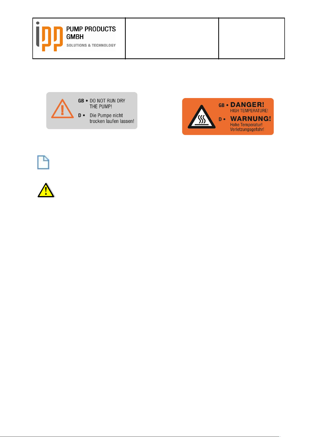
On the surface of the different components of the iLobe rotary lobe pump there are warning tags which
prohibit the dry running of the pump (tag A). If the iLobe rotary lobe pump has been designed for
liquids over 50°C there is a tag on the pump warning of hot surfaces (tag B).
A B
NOTE
Please note that the markings / tags at the iLobe rotary pump may not be changed or removed.
WARNING
It is not allowed to use any IPP Pump Products GmbH item without its identification plate. Should an
item be without its identification plate the customer has to contact IPP Pump Products GmbH technical
office so that the item can be identified and a new identification plate can be issued.
4 Terms and definitions
Dangerous areas: any area inside and / or in proximity of a machine in which the presence of an
exposed person constitutes a risk for the safety and health of this person.
Exposed person: any person who finds himself either entirely or in part in a dangerous area.
Machine: Assembly of parts: according to definition in article 2 of the Directive 2006/42/EC of the
European Parliament and the council of 17th May 2006.
Manufacturer: IPP Pump Products GmbH
Customer: Physical or legal person on whose behalf the machine is built, upon prior written
acceptance of an order confirmation.
Copyright: 2012 IPP Pump Products GmbH
Date of release: 12.06.2012
Doc. number: 0179 – Date 10/2013
Doc. No. 0179 – status 03/2017
Page 8

Operating instructions
iLobe
Rotary Lobe Pump
Date: 15.03.2017
Page 8 of 63
Doc. No. 0179
Est: D. Lünnemann /
W. Stein
WARNING!
All work on and with the pump must always be in accordance with all the prevailing standards
regarding occupational health and safety as well as machine safety.
Never let the pump run without pump cover or without being connected to the piping!
The pump may never be put into operation if the coupling is not provided with a proper coupling
protection.
When performing maintenance work to the pump, ensure that the drive of the pump is shut down
and cannot be switched on unintentionally!
Always wear protective gloves and safety goggles when performing maintenance work to the
pump, if the pump conveys liquids which are a health hazard.
Ensure that the pump is depressurized when it must be disassembled for maintenance purposes!
Close any steam or heating water feeding pipes!
If the pump is provided with a heating jacket and / or conveys hot liquids, let the pump cool down
before starting maintenance work.
When lifting a pump or a pump unit it is not allowed to stand under the hoisted load.
Never insert your fingers into the pump case or into the connection ports. Even manually rotating
of the shaft can cause injuries!
Ensure that the drive motor cannot be started during works at the pump unit. Also ensure that the
rotating parts are completely covered.
If the pump has already been installed. Ensure that the pump is shut down and make sure that
the pump cannot be switched on unintentionally!
Any works at the electric drive motor may only be carried out by qualified staff!
A pressure relief valve may ONLY be disassembled if the pump stands still, has cooled down and
has been depressurized completely!
The pump cover may ONLY be disassembled if the pump stands still, has cooled down and has
been depressurized completely!
Doc. No. 0179 – status 03/2017
Page 9
Operating instructions
iLobe
Rotary Lobe Pump
Date: 15.03.2017
Page 9 of 63
Doc. No. 0179
Est: D. Lünnemann /
W. Stein
ATTENTION!
The piping system must ALWAYS BE CLEANED respectively be FREE OF SOLID MATTERS!
After each new installation of the system, after each work at the system and each opening of the
system an appropriate cleaning must be carried out!
If there is the risk of exceeding the maximum operating pressure an appropriate safety device
must be fitted to the pump, the motor or to the system!
Always check the alignment of the coupling between pump and drive motor after hoisting the
pump unit to its base plate.
A pump which is NOT equipped with a QUENCHED or FLUSHED shaft seal may NEVER be
installed in a position where it possibly could run DRY!
The pump may never run if the gearbox is not filled with oilappropriately!
The pump may never run with a closed pressure valve or blocked pressure pipe.
When the pressure relief valve is activated the pump may only continue running for a short period
in order to avoid the risk of overheating. A pressure relief valve is a safety device, not a flow
control!
Avoid extreme temperature fluctuations of the pumped liquid. This could cause damages to the
pump if the pump components expand / shrink.
The indicated maximum values for operating pressure, the speed and the temperature may never
be exceeded!
When emptying the pump make sure that it does not run dry! Dry running is only permitted if the
pump is equipped with a flushed shaft seal.
5 Intended use
The iLobe rotary lobe pump manufactured by IPP Pump Products GmbH has been designed and
manufactured for the installation in industrial plants of third parties. Its purpose is to pump liquids
which comply with the materials used in the construction of the pump.
For an appropriate installation all technical indications of these operating and maintenance instructions
must be complied with.
The utilization of the iLobe rotary lobe pump is only permitted within the admissible ranges of pressure
and temperature under consideration of chemical and corrosive influences.
Any utilization exceeding the indicated operating ranges and specifications is being considered as
improper use. Any damages resulting from this will void responsibility of the manufacturer and the user
bears the full risk.
Please contact IPP Pump Products GmbH if the pump shall be used for any other application or at any
other conditions than those which are part of the agreed specifications according to which the pump
had been selected.
DANGER
Any improper use of the iLobe rotary lobe pump is forbidden without the written permission of IPP
Pump Products GmbH.
Doc. No. 0179 – status 03/2017
Page 10

Operating instructions
iLobe
Rotary Lobe Pump
Date: 15.03.2017
Page 10 of 63
Doc. No. 0179
Est: D. Lünnemann /
W. Stein
6 Introduction
6.1 General information
These operating instructions contain important information about the correct installation, utilization and
maintenance of the pump.
Furthermore, this manual provides the necessary information for the installation staff / operating staff
in order to avoid injuries and problems during the installation and operation of the pump and in order
to guarantee the correct handling of the machine and ensure a perfect functioning of the pump.
This manual represents the most recent information regarding the pump types mentioned in this
manual at the time printing. IPP Pump Products GmbH reserves the right to modify the construction of
the mentioned pump types as well as the contents of this manual without prior or afterward notification.
ATTENTION
Read this manual thoroughly before installing, operating respectively repairing this pump. Ensure that
operators and technical maintenance staff are familiar with the symbols used and have understood the
content. The instructions of this manual must be followed step by step.
6.2 Warranty
Warranty is strictly limited to the conditions specified by IPP Pump Products GmbH and will only be
granted according to these conditions.
Warranty will only come into force provided that:
The pump has been installed and put into operation strictly in accordance with the instructions
given in this manual;
Any maintenance and repair works have been executed according to the instructions given in this
manual;
Only original IPP Pump Products GmbH parts or parts provided by IPP Pump Products GmbH
have been used for replacement;
The pump has been used according to the agreed conditions only;
The construction principle of the pump has not been changed by the buyer;
The damages in question are not result of work carried out by persons not qualified or appointed.
The damage has not been caused through force majeure.
6.3 Transport and receiving of the goods
Please make sure that the pump has not been damaged during transport. If any damage has
occurred, the transport company and IPP Pump Products GmbH must be notified of this immediately.
Doc. No. 0179 – status 03/2017
Page 11

Operating instructions
iLobe
Rotary Lobe Pump
Date: 15.03.2017
Page 11 of 63
Doc. No. 0179
Est: D. Lünnemann /
W. Stein
ATTENTION
In order to facilitate the transport on your premises and in order to protect the pump as good as
possible, please leave the pump on the pallet or in the crate as long as possible until it has reached its
final position.
6.4 How to identify the pump
The serial number and the model type of the pump can be seen on the identification plate. Please
always indicate the relevant serial number and model on any correspondence and order for spare
parts.
Manufacturer
Die iLobe – Rotary lobe pumps are manufactured by
IPP Pump Products GmbH
Feldmühlenweg 6 - 10
D- 49593 Bersenbrück
Phone +49 (0) 5439-80921-0
Fax. +49 (0) 5439-80921-20
info@pump-products.de
www.pump-products.de
7 Safety
7.1 General information
This manual provides the necessary information to prevent the installer / operator from injury or
discomfort during installation and operation of this pump and to ensure the correct use and reliable
performance of the pump.
Read this manually thoroughly before installing, operating or servicing this pump.
Make sure that operating and maintenance staffs are familiar with the contents of this manual and
with the relevant instructions.
Make sure that the operating and technical maintenance staffs are familiar with the symbols used.
Follow the instructions of this manual step by step.
This manual has to be stored at a place which is known and accessible to any user.
7.2 Staff
All personnel in charge of the installation, operation or maintenance of the pump must have received
the necessary training and qualification.
Doc. No. 0179 – status 03/2017
Page 12

Operating instructions
iLobe
Rotary Lobe Pump
Date: 15.03.2017
Page 12 of 63
Doc. No. 0179
Est: D. Lünnemann /
W. Stein
7.3 Precautions
When performing maintenance work to the pump ensure that the drive motor is shut down and
cannot be switched on unintentionally!
All work on and with the pump must always be in accordance with all the prevailing standards
regarding occupational health and safety as well as machine safety!
Always wear protective gloves and safety goggles if the pump conveys harmful liquids that may
cause injuries!
Make sure that the pump is depressurized if it has to be disassembled for overhaul!
Let the pump cool down first if it is fitted with heating jacket and / or if it is conveying hot liquids.
8 General information
8.1 Pumping principle
A lobe pump is a rotary positive displacement pump. The operating principle is based on the counterrotation of 2 rotors in a rotor case. Both rotors are fixed on shafts. The shafts are supported by a
bearing house, which is directly mounted on the rotor case. One shaft is driving the other one is driven
synchronously by timing gears. The rotors do run without contact in the rotor case. The chamber
between rotors and rotor case rotate from inlet to outlet. When passing the inlet, the atmospheric
pressure pushes liquid in the chamber which is then transported to the outlet and finally displaced. The
pumped product seals the clearances between the rotors and the clearances between the rotors and
the rotor case. Depending on the pumped liquid properties and the operation conditions, a rotary lobe
pump runs with slip.
8.2 Range of products
8.2.1 Connections
The range of products comprises pump types with connections DN40, DN 50, DN65, DN80 and
DN100. The pump can be assembled optionally with the connections in horizontal or vertical position.
Doc. No. 0179 – status 03/2017
Page 13
Operating instructions
iLobe
Rotary Lobe Pump
Date: 15.03.2017
Page 13 of 63
Doc. No. 0179
Est: D. Lünnemann /
W. Stein
Type
Displacement
[L/rev.]
max.
differential
pressure [bar]
max.
speed
[min-1]
Weight
[kg]
iL42i
0,03
8
1200
12
iL55sxx
0,01
15
1200
16,5
iL55sx
0,03
15
1200
16
iL55s
0,04
15
1200
16,5
iL55i
0,06
15
1200
17
iL55li
0,075
8
1200
17,5
iL55l
0,94
6
1200
18
iL63s
0,09
8
1000
20
iL63i
0,12
8
1000
20
iL63l
0,174
8
1000
21
iL85s
0,21
8
900
42
iL85i
0,28
8
900
45
iL85l
0,35
8
900
47
iL115s
0,55
8
800
108
iL115si
0,7 8 800
111
iL115i
0,95
8
800
114
iL115l
1,23
8
800
123
8.2.2 Shaft seals
The following shaft seals are available:
Single mechanical seal
Double mechanical seal with flushing or quench (with or without pressure)
Lip seal
8.2.3 Model types
NOTE
The given data are maximum limits. Depending on the individual duty conditions these limits can vary.
Doc. No. 0179 – status 03/2017
Page 14
Operating instructions
iLobe
Rotary Lobe Pump
Date: 15.03.2017
Page 14 of 63
Doc. No. 0179
Est: D. Lünnemann /
W. Stein
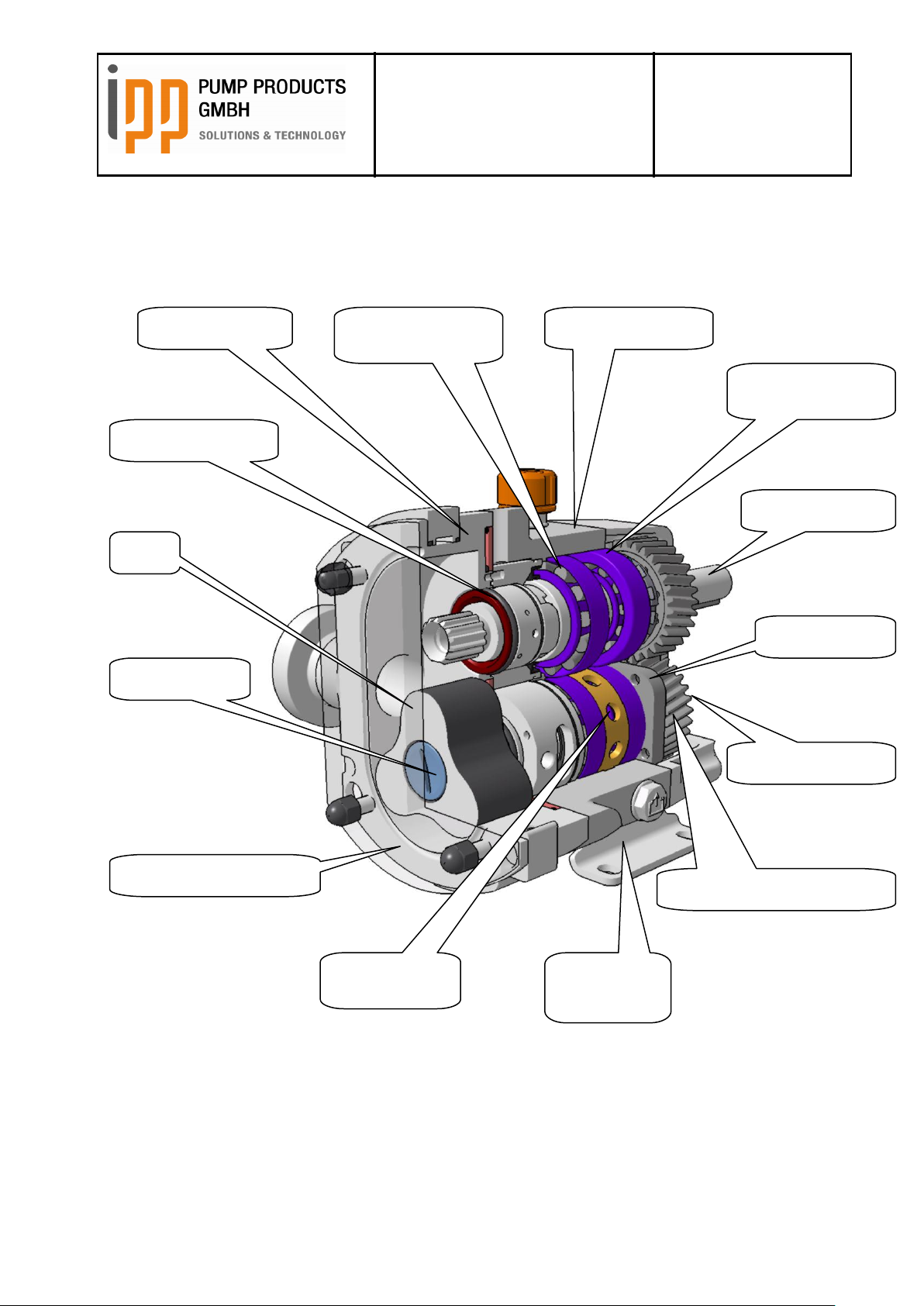
Frontal tapered
roller bearing
Bearing case
Pump case
Mechanical seal
Rotor
Rotor screw
Pump case cover
Spacer bush
Pump foot
Rear tapered roller
bearing
Driving shaft
Bearing cover
Driven shaft
Synchronisation gear wheels
9 Main components
The pump with its main components:
Doc. No. 0179 – status 03/2017
Page 15
Operating instructions
iLobe
Rotary Lobe Pump
Date: 15.03.2017
Page 15 of 63
Doc. No. 0179
Est: D. Lünnemann /
W. Stein
10 Installation
10.1 General information
The foundation must be solid, flat and even.
The area in with the pump unit is placed, must be well vented. Too high temperature, air humidity
or a dusty atmosphere may have negative effects to the performance of an electric motor.
The area around the pump-unit must be sufficient for the pump to be operated, cleaned or
repaired.
In order to ensure an unobstructed air supply to an electric motor there must be a free space
behind the fan cover, equal to ¼ of its diameter. For details, please refer to the manual of the
electric motor.
DANGER
Any works at or with the pump must always be carried out in accordance with the prevailing standards
regarding occupational health and safety as well as machine safety.
10.2 Transport
ATTENTION
In order to facilitate the transport of the pump on your premises, and in order to protect it as good as
possible, please leave the pump on the pallet or in the crate as long as possible until it has reached its
final position.
10.3 Storage Conditions
If the pump is not installed immediately following storage instructions have to be obeyed for a future
troublefree operation.
Store the pump at a temperature of ca. 20°C. Protect it against wetness, dust as well as against
mechanical influences and UV radiation.
If you plan to store the pump for more than one year, you should oil the coupling and fill the gearbox
completely with oil. Please note that before the pump is put into operation the oil filling level of the
gearbox has to be reduced to the operation level (see chapter 10.16 ). To avoid potential damage
caused by foreign objects in the pump, close the connections of the pump with the included sealing
caps.
In case the pump as already been in operation, clean it thoroughly both internally and externally. If the
pump is equipped with a flush tank, the flush tank and its connecting pipelines have to be completely
emptied and also cleaned thoroughly.
When the pump is stored with an engine, make sure the engine is protected against cold, dust and
especially wetness, even by air humidity. Furthermore, the instructions for storage and transport of the
manufacturer of the engine have to be obeyed.
To avoid potential damage on the gearbox and the mechanical seals, the shafts have to be checked
for ease of movement before putting into operation.
Doc. No. 0179 – status 03/2017
Page 16

Operating instructions
iLobe
Rotary Lobe Pump
Date: 15.03.2017
Page 16 of 63
Doc. No. 0179
Est: D. Lünnemann /
W. Stein
10.4 Lifting
If an appropriate lifting device is available, this shall be used for lifting the pump / pump unit.
DANGER
It is not allowed to stand under suspended loads!
If the pump is assembled with a motor on a base plate the hoisting slings for lifting the pump unit are
fixed as follows:
If a pump with bare shaft must be lifted, the hoisting slings are fixed as follows:
DANGER
Never insert your fingers into the pump case or into the connections. Even rotating the shafts by hand
might cause injuries!
ATTENTION
If there is the risk of exceeding the maximum operating pressure an appropriate safety device must be
fitted to the pump, the motor or to the system!
10.5 Foundation
The foundation must be solid, flat and level.
Doc. No. 0179 – status 03/2017
Page 17
Operating instructions
iLobe
Rotary Lobe Pump
Date: 15.03.2017
Page 17 of 63
Doc. No. 0179
Est: D. Lünnemann /
W. Stein
When planning the foundation take into consideration the drainage and required space for the pump
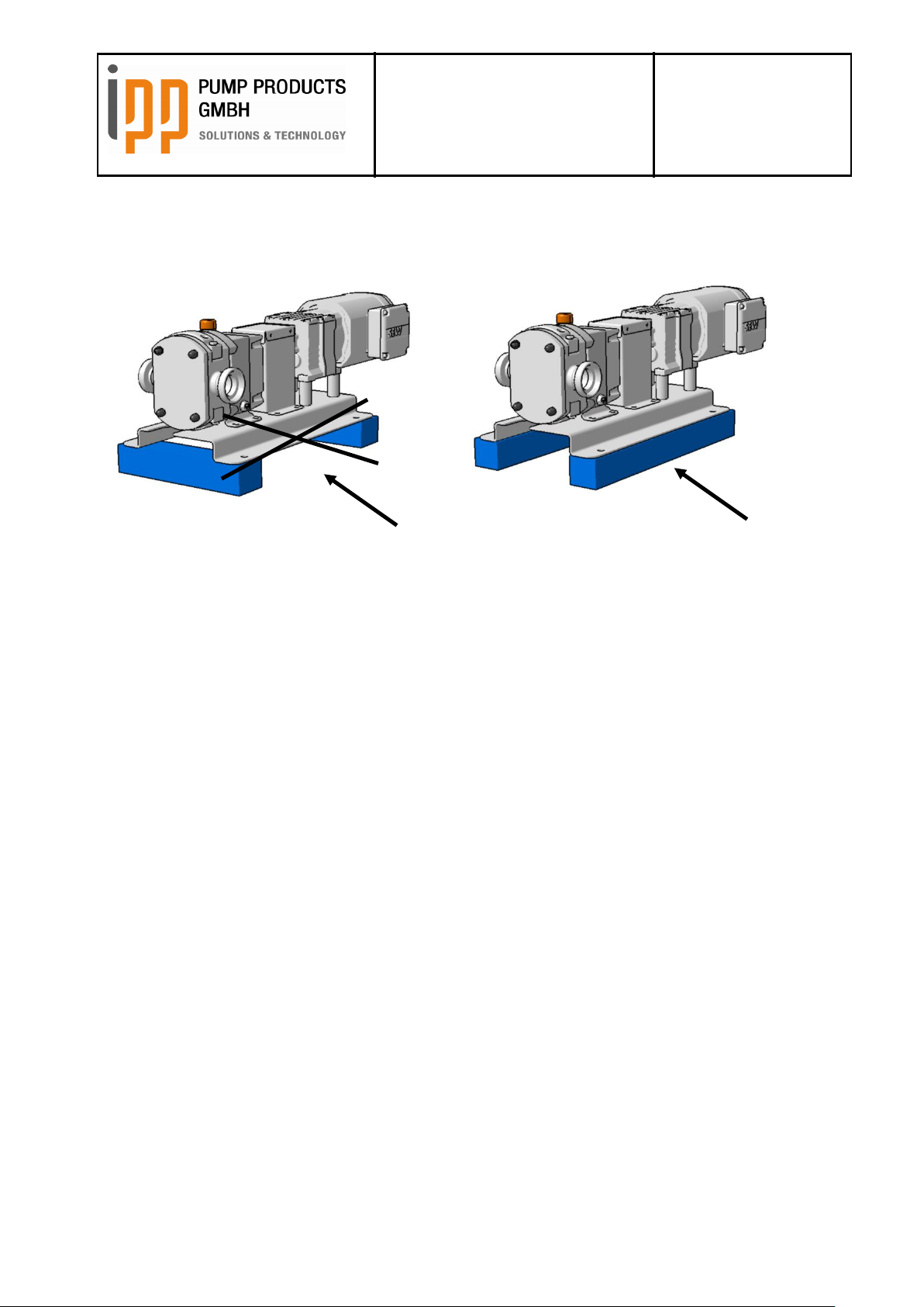
drainage as well as maintenance, assembly and service.
The base plate of the pump unit must be supported over the whole length and must be even on the
foundation. The base plate must not bend!
10.6 Installation dimensions
The correct installation dimensions of the pump unit are part of the unit drawing which has been
supplied with the pump or which can be obtained at IPP Pump Products GmbH.
For details regarding the most important dimensions of the bare shaft pump, please refer to chapter 18
of this manual.
10.7 Pipe system
The pipe system must comply with the following requirements:
Doc. No. 0179 – status 03/2017
Page 18
Operating instructions
iLobe
Rotary Lobe Pump
Date: 15.03.2017
Page 18 of 63
Doc. No. 0179
Est: D. Lünnemann /
W. Stein
10.7.1 General
Ensure that the piping system is sufficiently supported, especially at the inlet and outlet ports. The
piping must not weigh on the pump.
It must be possible to connect the ports on site in exact line to the inlet and outlet ports of the
pump.
The pipes must be fitted and connected stress-free.
Piping which is fitted obliquely insufficiently supported or which exerts force to the pump may
cause serious damages to the pump!
Please also consider thermo tensions which can cause improper forces to the pump.
Ensure that there is no leakage at the piping and connections.
10.7.2 Inlet piping
It is recommended to place the pump below the supply liquid level. A flooded suction reduces the
presence of air in the system.
10.8 Non-return valve
In case the pump is installed above the liquid level, a non-return valve must be fitted to the foot of the
suction line in order to keep it filled with liquid. This applies especially when low-viscous liquids are
conveyed.
For systems that convey liquid under vacuum, a non-return valve in the delivery line is recommended.
This prevents backflow of air or liquid.
Doc. No. 0179 – status 03/2017
Page 19

Operating instructions
iLobe
Rotary Lobe Pump
Date: 15.03.2017
Page 19 of 63
Doc. No. 0179
Est: D. Lünnemann /
W. Stein
10.9 Pump with pressure relief valve
If the pump is fitted with a pressure relief valve at the pump cover it is compulsory to install a pressure
gauge at the pressure side and a shut-off valve directly after the pressure gauge. These are needed
for the adjustment of the reaction pressure. The pressure gauge must have a measuring range of at
least 0-25 bar.
10.10 Assembly of the pump unit
If the pump has been supplied with bare shaft it must be assembled to a drive motor and assembled
on a base plate.
This is done as follows:
Place the pump onto the base plate and fix it with appropriate retaining bolts.
Fix one part of the coupling onto the pump shaft.
Fix the other part onto the shaft of the drive.
Now place the drive onto the base plate. Leave a distance of app. 3 mm between the two coupling
parts.
Align the drive to the pump. Therefore place the copper plates under the pump feet. Then the drive is
fixed.
The coupling must be aligned according to the following instructions.
10.10.1 Alignment of the coupling
After the assembly and the set-up of the pump unit the alignment of the coupling must be checked.
It is necessary to check the alignment of the coupling always when the pump unit is detached from the
base plate!
NOTE
Misalignment can cause excessive wear and increased motor temperatures and noise level.
Check the alignment by means of special equipment or do the following:
Place a ruler on the coupling. It must touch the coupling parts over the complete width, see figure.
Repeat this check at three different positions around the coupling;
Check the alignment by means of a pair of outside callipers at 2 diametric opposite positions at the
lateral faces of the coupling, see figure.
If the measured values are outside the tolerance limits, slightly loosen the retaining bolts of the drive
and move the drive until the values are within their tolerance limits. Re-fix the retaining bolts. If the
alignment is correct, the coupling protection is fitted.
Doc. No. 0179 – status 03/2017
Page 20

Operating instructions
iLobe
Rotary Lobe Pump
Date: 15.03.2017
Page 20 of 63
Doc. No. 0179
Est: D. Lünnemann /
W. Stein
Outside diameter
coupling [mm]
A must be
between [mm]
Max. balance
between A
max
and
A
min
[mm]
E must be
between [mm]
81-95
2 – 4
0,15
0 - 0,15
96-110
2 – 4
0,18
0 - 0,18
111-130
2 – 4
0,21
0 - 0,21
131-140
2 – 4
0,24
0 - 0,24
141-160
2 – 6
0,27
0 - 0,27
161-180
2 – 6
0,30
0 - 0,30
181-200
2 – 6
0,34
0 - 0,34
201-225
2 – 6
0,38
0 - 0,38
10.10.2 Alignment tolerances
The following table with its corresponding figure shows the tolerance limits for aligning the coupling:
Doc. No. 0179 – status 03/2017
Page 21

Operating instructions
iLobe
Rotary Lobe Pump
Date: 15.03.2017
Page 21 of 63
Doc. No. 0179
Est: D. Lünnemann /
W. Stein
10.11 Connection of the pipes
DANGER
Ensure that the motor CANNOT be started during any works carried out at the pump unit and with the
rotating parts not completely covered!
ATTENTION
The pipe system must ALWAYS be CLEANED respectively free of solid matters! After the new
installation of the system as well as after each work at the system and after each opening of the
system an appropriate cleaning must be carried out! Debris and solid matters can cause serious
damages!
ATTENTION
A pump which is NOT equipped with a QUENCHED shaft seal may never be installed in a position
where it possibly could run DRY!
10.12 Flushing of the shaft seals
The connection of the flushing pipes is done by means of the openings in the pump case. The
connections are threaded G1/8“ as standard or DIN ISO DN08 BBS-connections.
If a low-pressure flushing or– Quench is used, the flushing system must have a capacity of 2,5 l/min at
max. 0,2 bar. If the ports are fitted in vertical position: connect the flushing pipes at the bottom side!
If a pressure flushing (Flush) is used the pressure of the flushing system must be app. 2 bar higher
than the pressure of the system. Capacity of 2,5l / min. If the connection ports are fitted in vertical
position: connect the supply line at the bottom side.
Doc. No. 0179 – status 03/2017
Page 22

Operating instructions
iLobe
Rotary Lobe Pump
Date: 15.03.2017
Page 22 of 63
Doc. No. 0179
Est: D. Lünnemann /
W. Stein
degassing/ compressed air supply
maximum 16bar
donwstream
mechanical seals
pipe/tube Ø6mm
upstream mechanical seals
pipe/tube Ø6mm
10.13 Barrier pressure tank / Barrier fluid tank
The barrier pressure tank is delivered from the factory without barrier fluid. To avoid damages to the
mechanical seals the barrier pressure tank must be filled with a suitable liquid before start-up of the
pump.
The barrier pressure tank can be operated depressurized or under pressure. When operating under
pressure the sealing pressure must be app. 2 bar higher than the operating pressure of the pump to
be sealed. The sealing pressure must not exceed the admissible pressure of 16 bar.
If the barrier pressure tank is operated depressurized, it serves as quench tank and consequently the
liquid is a flush fluid.
10.13.1 Overview barrier pressure tank
Doc. No. 0179 – status 03/2017
Page 23
Operating instructions
iLobe
Rotary Lobe Pump
Date: 15.03.2017
Page 23 of 63
Doc. No. 0179
Est: D. Lünnemann /
W. Stein
filling level
10.13.2 Assembly and connection of the tank
In general the barrier pressure tank is delivered connected to the pump with hoses and fixed onto the
base plate. In special cases it might be possible that the barrier pressure tank is not delivered
assembled and must be installed by the customer on site. In case of a later assembly the following
points must be observed:
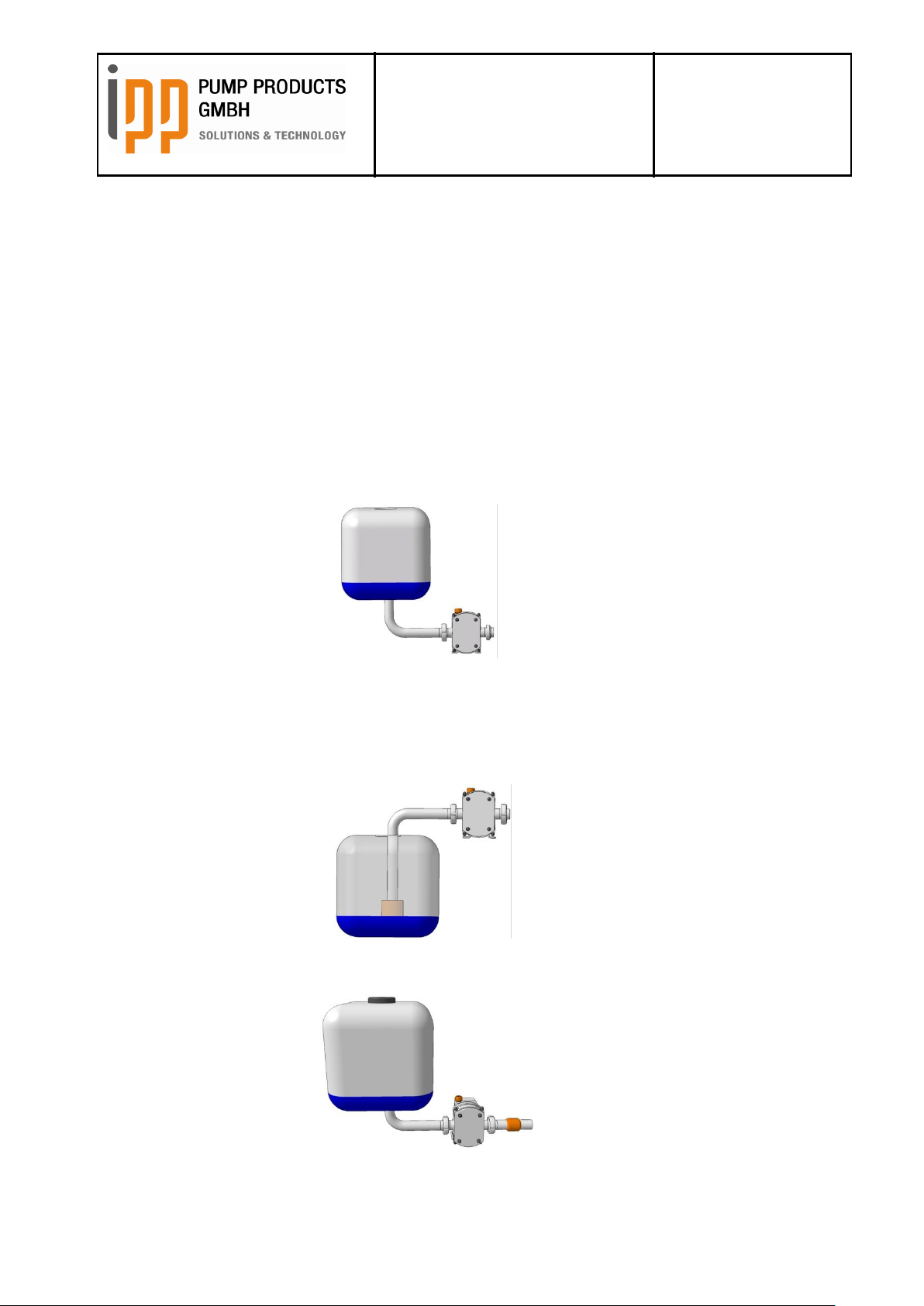
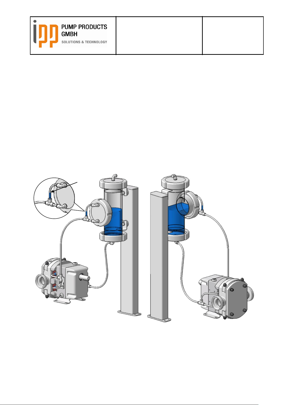
As this barrier pressure unit is a buffer system with thermosiphon circuit the barrier pressure tank must
be arranged in a way that the pipes leading to the mechanical seal are continuously declining and the
pipes from the mechanical seals to the barrier pressure tank are continuously rising.
In case of a horizontal position of the connection ports the pipes can either be connected serially or in
parallel. If the mechanical seals should be flushed in parallel it must be observed that the T-piece of
the flow pipe is not positioned above the bottom flush connection. The T-piece of the return pipe
should be installed at least on the same height as the top flush connection. When laying the pipes
respectively hoses it must always be made sure to prevent a later formation of lumps in order to
guarantee the perfect circulation of the barrier liquid.
Doc. No. 0179 – status 03/2017
Parallel flushing mechanical seals
Page 24
Operating instructions
iLobe
Rotary Lobe Pump
Date: 15.03.2017
Page 24 of 63
Doc. No. 0179
Est: D. Lünnemann /
W. Stein
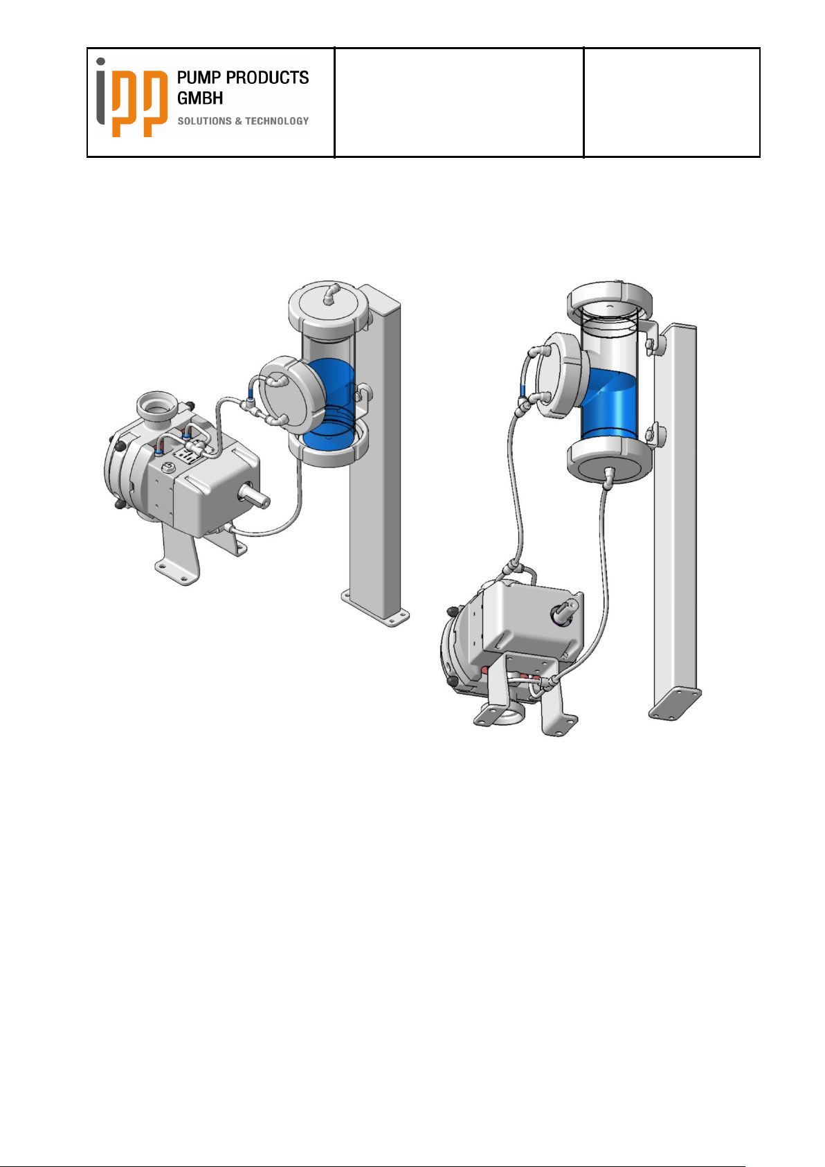
If the pump position is vertical the flush pipes can only be connected in parallel. The feed must be at
the bottom part and the return at the top part of the pump.
The ports can be connected with hoses or pipes. The selection of the material depends on the
application field and on the barrier liquid and must be done by the customer himself.
10.13.3 Selection of barrier fluid
The barrier fluid must be compatible to the pumped fluid to be sealed, it must have suitable lubricating
characteristics and sufficient heating capacity. In case of ATEX-execution it must further be observed
that the barrier fluid is electrically conductive.
The barrier fluid should be soluble in the pumped fluid in order to guarantee a mixing of both fluids and
a complete and thorough flushing of the mechanical seals.
When selecting the O-rings and seals which get in contact with the flushing fluid these must be
checked for compatibility with the selected barrier fluid.
Doc. No. 0179 – status 03/2017
Flushing of mechanical seal vertical
Page 25

Operating instructions
iLobe
Rotary Lobe Pump
Date: 15.03.2017
Page 25 of 63
Doc. No. 0179
Est: D. Lünnemann /
W. Stein
10.13.4 Filling and emptying the tank
DANGER
Never open a barrier pressure tank under pressure. Before opening the barrier pressure system must
always be completely depressurized. To avoid scalding by escaping barrier fluid let the barrier
pressure system cool down before opening.
For filling the barrier pressure tank must be opened by screwing off the upper locknut with a suitable
tool (e.g. hook wrench for locknut DN80). The system is being filled until the filling level has reached
the middle of the hose between T-piece and upper entry of the barrier fluid tank (see 10.13.2).
At special executions with sight glass the filling level should be app. in the middle of the sight glass. If
a filling level monitoring system is installed the operating manual of the system must be observed.
ATTENTION
On any variation of barrier pressure tanks the circulation system must always be closed.
Then the barrier fluid tank is closed with the locknut and can be put into operation.
The change of the barrier fluid should be done in suitable intervals. For this purpose the feed pipe is
loosened at the lowest point and the barrier fluid tank and the drain pipe are emptied. To remove
residual liquid in the mechanical seals the detached feed pipe is closed and an air pressure pipe is
connected to the upper connection port of the tank. Then the open circuit is pressurized. Afterwards
the system can be cleaned and the barrier pressure tank can be refilled.
Doc. No. 0179 – status 03/2017
Page 26

Operating instructions
iLobe
Rotary Lobe Pump
Date: 15.03.2017
Page 26 of 63
Doc. No. 0179
Est: D. Lünnemann /
W. Stein
Inlet
Inlet
Outlet
Direction of rotation
Outlet
Direction of rotation
10.14 Direction of rotation
ATTENTION
Never operate the pump without pump cover or without being connected to the pipes!
Before connecting the drive to the power supply, the correct direction of rotation of the drive shaft must
be established. The pump operates in both directions. At the same time the drive shaft can have
different positions. See the following figure to establish the correct direction of rotation of the drive
shaft.
10.15 Connection of the drive
DANGER
The pump may never be put into operation unless the coupling is not provided with a proper protection
device!
When driven by an electric drive motor the following must be considered:
DANGER
An electric drive may only be connected to the electric power supply by a qualified electrician!
Before connecting an electric drive motor, please acquaint yourself with the actual regulations of the
local electric works.
Protect the drive against overload.
If possible, fit an operation switch at the pump.
If possible, mount an earth switch.
Doc. No. 0179 – status 03/2017
Page 27

Operating instructions
iLobe
Rotary Lobe Pump
Date: 15.03.2017
Page 27 of 63
Doc. No. 0179
Est: D. Lünnemann /
W. Stein
max
min
max.
min
Oil filler - horizontal
Oil filler - vertical
10.16 Filling with oil
The gearbox of a new pump has been filled with oil by the manufacturer!
Unscrew the venting plug together with the oil dipstick.
Fill the oil through the filling opening into the gearbox. The relevant quantities can be found in chapter
15. Check the oil level by means of the oil dipstick. For this purpose screw in and out by hand the
dipstick. The oil level must be between the top and bottom limit. When the correct oil level is reached,
tighten the oil dipstick by hand.
Doc. No. 0179 – status 03/2017
Page 28
Operating instructions
iLobe
Rotary Lobe Pump
Date: 15.03.2017
Page 28 of 63
Doc. No. 0179
Est: D. Lünnemann /
W. Stein
11 Commissioning
11.1 Cleaning of the system
Rotary lobe pumps are particularly sensitive to conveying solid particles. Newly installed systems or
overhauled systems often contain hard particles from welding, grinding or other mechanical work.
When flushing the system those hard particles can get stuck between the pump elements of the rotary
lobe pump and cause severe damage when starting the pump. For initial cleaning of the system rotor
dummies can be used which allow those particles to pass the pump without causing damages.
For a correct fitting and disassembly of the rotors, please refer to the instructions in chapter 13.6 and
13.7.
Rotor dummies are available at IPP Pump Products GmbH.
11.2 Control
Please check if there’s enough oil in the gearbox. The oil level must be between the top and bottom
limit marked at the oil dipstick. (see chapter 10.14).
ATTENTION
Never start the pump when the gearbox is not filled with oil correctly!
If connected, check the pressure of the flushing system.
If a double mechanical seal is fitted, the non-pressurized flushing (quench) must have a capacity of 2,5
l/min. If the ports are fitted in vertical position: connect the supply lines of the flushing system at the
bottom side!
If a double mechanical seal is fitted the pressurized flushing (Flush) must be app. 2 bar higher than the
system pressure. Capacity of 2,5 l / min. If the connection ports are fitted in vertical position: connect
the supply line at the bottom side.
If connected, check if the heating system has the required temperature.
Doc. No. 0179 – status 03/2017
Page 29

Operating instructions
iLobe
Rotary Lobe Pump
Date: 15.03.2017
Page 29 of 63
Doc. No. 0179
Est: D. Lünnemann /
W. Stein
11.3 Start-up
Open – if existing – the non-return valves of the flushing pipes.
Open – if existing – the non-return valve at the outlet.
Open – if existing – the non-return valve at the inlet.
Start the pump unit.
11.4 During operation
ATTENTION
If it is not fitted with a pressure relief valve, the pump may never run with closed non-return valve or if
the outlet is blocked. If the pressure relief valve is activated, the pump should not run to long in order
to avoid overheating! A pressure relief valve is a protective device, not a control valve.
NOTE
Avoid strong temperature changes of the pumped liquid. This could cause damages to the pump if the
pump components expand or shrink. The indicated limits for pressure, speed or temperature must not
be exceeded!
11.5 To stop the pump for a short period
When interrupting or stopping the pumping procedure it must be ensured that the pump does not run
dry! This is only admissible if the pump is fitted with a flushed shaft seal.
Stop the pump by switching off the drive motor.
If the system stays pressurized, leave the non-return valves of the flushing pipes (if existing) OPEN.
If the pump is fitted with heating jackets, leave the non-return valves (if existing) at the heating system
OPEN, if the pump conveys liquids which can get solid at lower temperatures.
Doc. No. 0179 – status 03/2017
Page 30

Operating instructions
iLobe
Rotary Lobe Pump
Date: 15.03.2017
Page 30 of 63
Doc. No. 0179
Est: D. Lünnemann /
W. Stein
12 Maintenance
12.1 General
The following points have to be checked regularly:
Perfect functioning of the pump. Excessive noise can be caused by worn bearings, problems at
the gear wheels, galling rotors or cavitations.
Check for leakage at the shaft seals.
If applicable: pressure and capacity of the flushing system.
If applicable: temperature of the heating system
The oil level: If the oil level is reduced, check the pump for oil leakage. If the oil level is increased,
check the oil for entry of water or product to be pumped.
Pressure at the inlet and outlet ports.
Visual control: check for corrosion.
12.2 Oil change
The gearbox oil should be changed every 3000 operating hours or at least 1 x per year. Please see
chapter 15.1 and 15.2 for oil specifications.
13 Disassembly / Assembly
13.1 Order of spare parts
When ordering spare parts please indicate the following:
The serial number. This can be found on the identification plate of the pump.
The model type: This can be found on the identification plate of the pump.
The position number, quantities and – if known – part no. of the requested spare parts.
Chapter 16 shows a cross-sectional drawing of the pump with a spare parts list and the correct
position numbers. Rotors and gear wheels are always supplied as a pair!
Doc. No. 0179 – status 03/2017
Page 31

Operating instructions
iLobe
Rotary Lobe Pump
Date: 15.03.2017
Page 31 of 63
Doc. No. 0179
Est: D. Lünnemann /
W. Stein
Type
Part No.
iL42
110.1003.01F000
iL55
110.1003.01F000
iL63
210.1003.00F000
iL85
220.1003.00F000
iL115
230.1003.00F000
Type
Part No.
iL42
260.1006.01C000
iL55
250.1006.01C000
iL63
210.1006.01C000
iL85
220.1006.01C000
iL115
230.1006.01C000
13.2 Precautions
DANGER
Never let the pump run without pump cover or without having the pipes connected appropriately!
DANGER
It must be ensured that the drive of the pump is switched off during maintenance works and cannot be
re-started unintentionally!
DANGER
If the pump possibly conveys liquids which are harmful to health, please wear protective gloves and
goggles when working at the pump!
DANGER
Ensure that the pump is depressurized when it must be disassembled for maintenance purposes!
13.3 Special tools
13.3.1 Rotor key
13.3.2 Auxiliary tool for assembly
13.4 Pump drainage
Close the non-return valves at the inlet and outlet ports of the pump. If there are no non-return
valves, it must be ensured that the liquid level of the pipe system is under the pump level.
Place a collection tank at the front under the pump case.
Loosen partly the cap nuts at the pump case cover.
Insert a screwdriver into the recesses provided for this and lift the pump case cover from the
pump case.
Collect the leaking liquid in the collection tank underneath the pump case.
Doc. No. 0179 – status 03/2017
Page 32
Operating instructions
iLobe
Rotary Lobe Pump
Date: 15.03.2017
Page 32 of 63
Doc. No. 0179
Est: D. Lünnemann /
W. Stein
If there is no more liquid leaking re-tighten the cap nuts by hand.
13.5 Oil drainage
Place a collection tank under the drainage opening of the gearbox cover.
Unscrew the oil vent plug on top of the pump.
Remove the oil drain screw at the bottom of the gearbox cover and drain the oil into the collection
tank.
After complete drainage screw the oil vent plug and the oil drain plug into their positions.
NOTE
It must be ensured that no oil leakage is contaminating the environment.
13.6 Dismantling of the pump
Remove the coupling protection
Loosen the coupling part on the pump shaft and push the coupling part backwards.
Loosen – if existing – the flushing tubes from the shaft seal.
Loosen – if existing – connections at the pressure relief valves and other safety valves.
Loosen – if existing – the steam and heating pipes from the heating jacket.
DANGER
Ensure that the feeding of steam or heating liquid is closed and that the heating jacket has cooled
down!
Loosen the connections from the pressure and suction connection. Make sure that the piping is
well-supported!
Unscrew the bolts and remove the pump from the base plate. If necessary, use an appropriate hoisting
device. For detailed hoisting instructions, please refer to chapter 10.3 of this manual.
13.7 Disassembly of the pump
En explanation of the position numbers can be found in the cross-sectional drawing with part list in
chapter 16.
Place the pump onto a bench which is suitable to carry the pump weight.
NOTE
In order to catch residual oil and product liquid it is recommended to put the pump in a large basin
Doc. No. 0179 – status 03/2017
Page 33

Operating instructions
iLobe
Rotary Lobe Pump
Date: 15.03.2017
Page 33 of 63
Doc. No. 0179
Est: D. Lünnemann /
W. Stein
Blocking piece
mechanical
seal
Lip seal
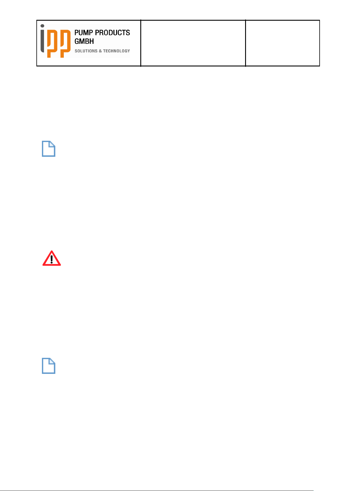
13.7.1 Disassembly of the rotors
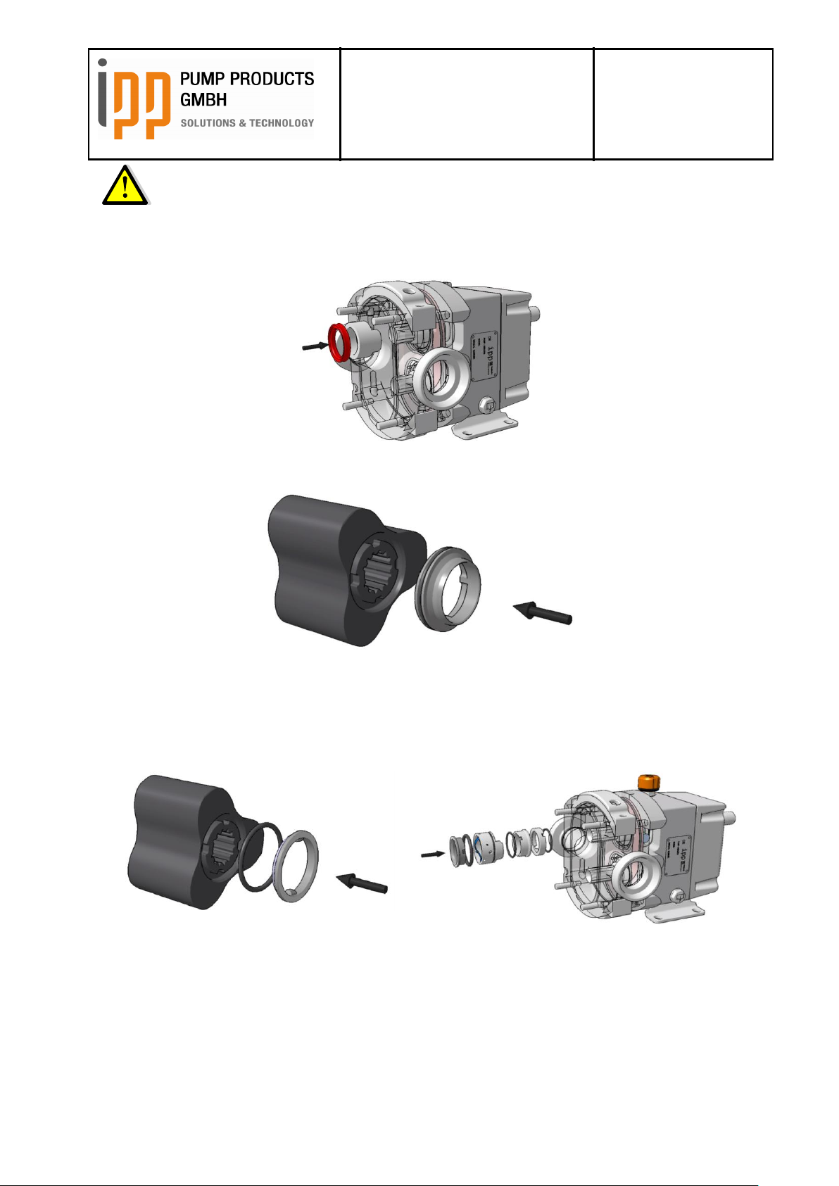
Remove the cap nuts and pull off the pump case cover and the o-ring respectively profile shape
gasket.
Unscrew the rotor screw by means of the supplied rotor key and remove the rotor screw with the orings. Use the auxiliary tool in order to prevent the rotor key from gliding off and thus damaging the
rotor screw. When tightening the auxiliary tool, make sure that the rotor screw still can rotate. When
loosening and tightening the rotor screw follow the instructions regarding the auxiliary tool in the same
way.
Put a soft plastic block between the rotor and the rotor case in order to prevent them from rotating.
Remove the rotors from the shafts.
13.7.2 Disassembly of the shaft seals
The rotating sliding ring or shaft protection bush is located in the recesses in the already disassembled
rotors. Remove these sliding rings or shaft protection bush by lifting them up carefully by means of a
screwdriver or another suitable tool.
ATTENTION
Exercise extreme care! In no case you should use a striking tool and you should not exercise bumping
movements with the screw driver.
Doc. No. 0179 – status 03/2017
Page 34

Operating instructions
iLobe
Rotary Lobe Pump
Date: 15.03.2017
Page 34 of 63
Doc. No. 0179
Est: D. Lünnemann /
W. Stein
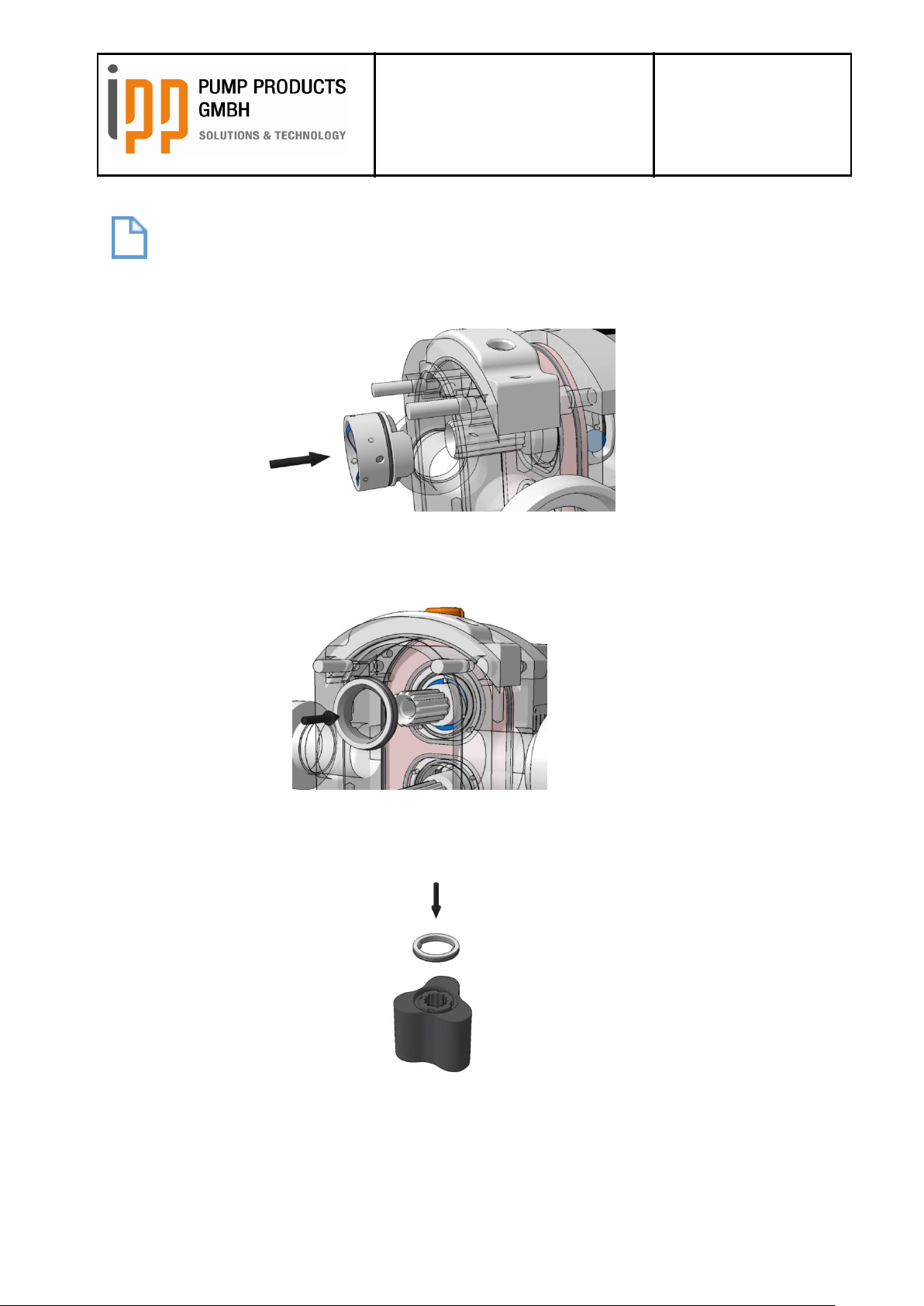
The other parts of the shaft seals are disassembled as follows:
Insert a screw driver on both sides of the shaft into the assembling openings on both sides of the
pump case.
Place the screw driver or another suitable tool behind the visible edges of the seal case.
Now lift up carefully (by using both screw drivers at the same time) the seal case with the shaft seal to
the front out of the pump case.
Remove the seal case with the shaft seal from the front from the shaft.
Remove the other shaft seal in the same way. Take care not to exchange the two sliding rings of the
mechanical seal when assembling the mechanical seal again. The sliding rings have been adjusted to
each other and must not be exchanged!
Doc. No. 0179 – status 03/2017
Page 35

Operating instructions
iLobe
Rotary Lobe Pump
Date: 15.03.2017
Page 35 of 63
Doc. No. 0179
Est: D. Lünnemann /
W. Stein
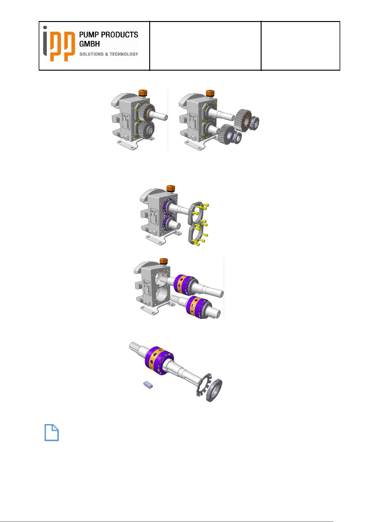
13.7.3 Disassembly of the gearbox
Continue the disassembly as follows: Ensure that there is no more oil left in the gearbox!
Remove the feather key out of the driving shaft.
Loosen the locking screws of the gearbox cover. Insert a screw driver or another suitable tool into the
recesses of the gearbox cover and lift the cover up from the bearing case.
Remove the flat gasket.
Screw off the heating covers at the pump case and remove these.
DANGER
ATTENTION: Hot surfaces, do not touch!
Place the pump on the stay bolts of the pump case and pull up the bearing case together with the
shafts. Use a suitable hoisting device.
Doc. No. 0179 – status 03/2017
Page 36
Operating instructions
iLobe
Rotary Lobe Pump
Date: 15.03.2017
Page 36 of 63
Doc. No. 0179
Est: D. Lünnemann /
W. Stein
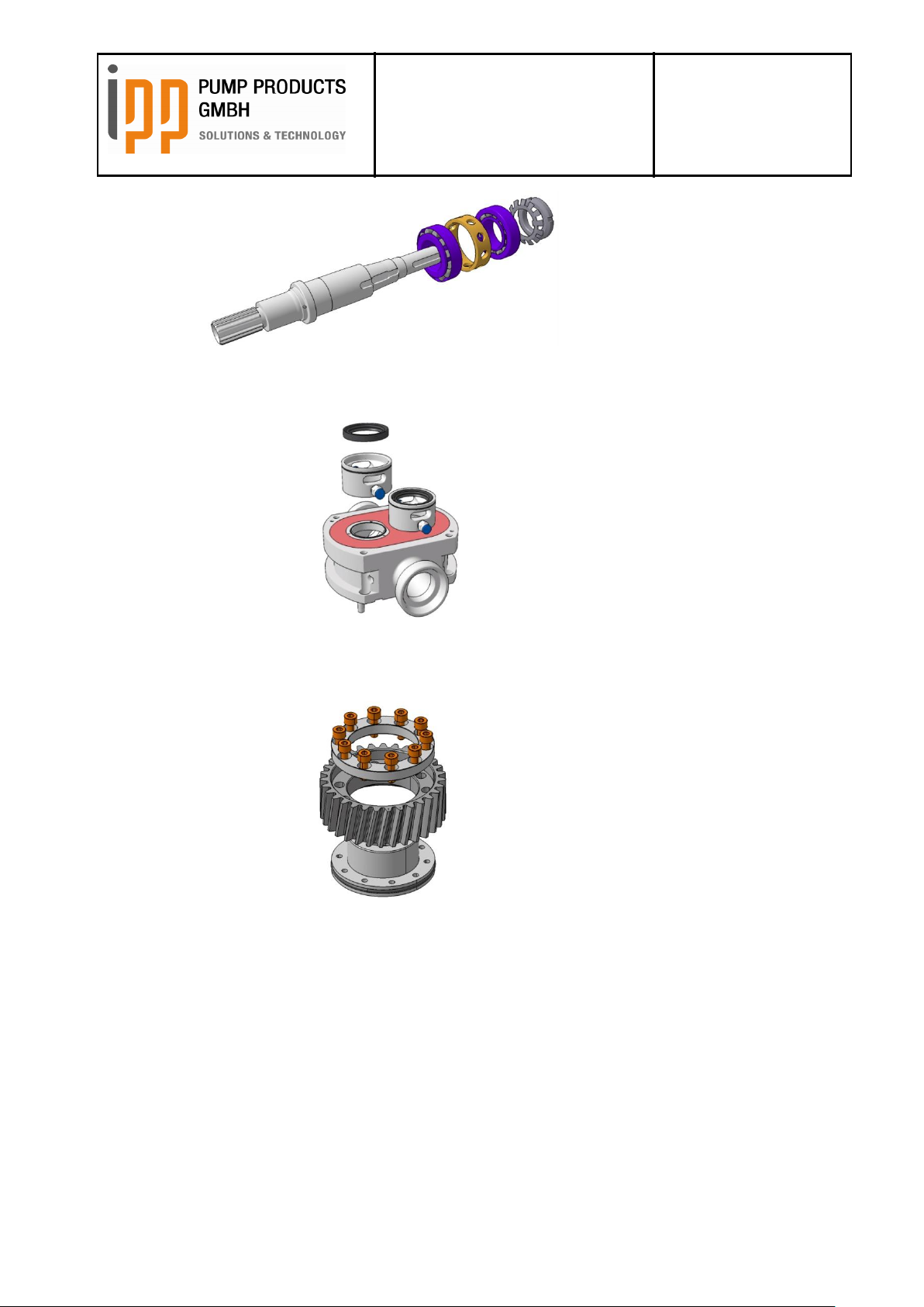
Unlock the groove nuts of the gear wheels and loosen the groove nuts.
Pull of the gear wheels from the shafts. A puller or a lever may be a helpful tool.
Remove the feather keys. Remove the bearing covers.
Press the shaft units off the bearing housing by applying a press.
Remove the feather keys, unlock the groove nuts and loosen these.
Use a press to pull off the bearings from the shaft.
NOTE
Attention: Do not damage or scratch the seal faces of the shaft seals.
Doc. No. 0179 – status 03/2017
Page 37
Operating instructions
iLobe
Rotary Lobe Pump
Date: 15.03.2017
Page 37 of 63
Doc. No. 0179
Est: D. Lünnemann /
W. Stein
You can lift off spacer bushing I and spacer bushing II from the pump case. Pull out the radial shaft
seals out of the spacer bushings. Don’t damage the seal seat!
Loosen the support ring from the gear of the driven shaft and separate the sprocket wheel from the
centre sleeve.
13.7.4 Control of the parts
Only use original - IPP Pump Products GmbH –parts for replacement of defective parts.
Check all radial shaft seals for leakages and damages.
Check all non-defective for scratches, burrs, debris or excessive wear.
If the gearbox cover has already been disassembled: Ensure that the sealing surface between pump
case and gearbox cover are clean and free of sealing residues. Clean all parts with a lint-free cloth.
Doc. No. 0179 – status 03/2017
Page 38
Operating instructions
iLobe
Rotary Lobe Pump
Date: 15.03.2017
Page 38 of 63
Doc. No. 0179
Est: D. Lünnemann /
W. Stein
Type
Torque
iL42
1,4 – 1,6 Nm
iL 55
1,5 – 1,8 Nm
iL63
1,8 – 2,0 Nm
iL85
2,0 – 2,5 Nm
iL115
3,5 – 4,0 Nm
13.8 Assembly of the pump
In chapter 16 you find a cross-sectional drawing with part lists and an explanation of the position
numbers.
If the pump is fitted with Quattro-lobe rotors the synchronised running must always be adjusted after
installation of new bearings or disassembly of the bearing units.
Ensure that all parts are clean; a clean working environment is helpful for successful assembly!
Install the front bearing onto the shaft.
DANGER
We recommend heating the bearing to app. 100 to 150°C. (Attention: Heat can cause severe injury)
DANGER
Install the spacer bushing and the rear bearing. This should also be heated to app. 100 – 120°C.
(Attention: Danger of injury by hot parts)
Work rapidly in order to prevent bearings from cooling down too early.
Pretension the bearing by mounting the lock washer and tighten the shaft nut.
The pretension must be adjusted to the following friction torques of the bearing: We recommend using
a torque gauge. If required, please contact IPP Pump Products GmbH. Please adjust the following
friction torques:
Doc. No. 0179 – status 03/2017
Page 39

Operating instructions
iLobe
Rotary Lobe Pump
Date: 15.03.2017
Page 39 of 63
Doc. No. 0179
Est: D. Lünnemann /
W. Stein
Feather keys in 12 o’clock
position
Markings gear into
each other
Insert the feather keys and press the shafts into the bearing case (use a press).
Now place the bearing covers onto the shaft ends. Don’t tighten the bearing covers yet.
Now install the gear wheels and tighten them and lock the screwing.
It is important that the feather keys are in a 12 o’clock position and that the markings of the tooth
flanks gear into each other. In this position, install the fixing ring and the screws. Just pull hand-tight in
order to be able to adjust the final timing later.
Prepare the pump case by inserting the radial shaft seals into the spacer bushing I and spacer
bushing II. Ensure that the radial shaft seals and the sealing surfaces are free of damages. Insert the
o-rings into the pump case. Insert the o-rings into the grooves of the spacer bushings.
If the pump is fitted with a heating system the o-rings and the heating plate are inserted into the
position provided for these (see chapter „heating“). Place the spacer bushings into their position.
Doc. No. 0179 – status 03/2017
Page 40

Operating instructions
iLobe
Rotary Lobe Pump
Date: 15.03.2017
Page 40 of 63
Doc. No. 0179
Est: D. Lünnemann /
W. Stein
Place the bearing case with the shafts onto the pump case. Pay attention when passing the shafts: the
radial shaft seals can easily be damaged.
Place the pump onto the pump feet and tighten the bearing case.
13.8.1 Mechanical seals
13.8.1.1 Single mechanical seals
Insert the shaft spring into the mechanical seal housing.
Doc. No. 0179 – status 03/2017
Page 41

Operating instructions
iLobe
Rotary Lobe Pump
Date: 15.03.2017
Page 41 of 63
Doc. No. 0179
Est: D. Lünnemann /
W. Stein
Push the seal housing into the pump case so that the pins fit into the slots provided for these. The
slots are in one line with the leakage holes.
Now insert the fixed sliding rings together with the o-ring. We recommend placing the o-ring onto the
sliding ring first. Take care that the cylindrical pins of the seal housings fit into the driving slots of the
sliding rings. Attention: Grease the o-rings with an appropriate lubricant.
Now insert the rotating sliding rings with the installed o-ring into the rotors. Ensure that the pins of the
sliding ring fit into the slots of the rotor. Attention: Grease the o-rings with an appropriate lubricant.
Clean the sliding surfaces and insert the rotors.
Doc. No. 0179 – status 03/2017
Page 42
Operating instructions
iLobe
Rotary Lobe Pump
Date: 15.03.2017
Page 42 of 63
Doc. No. 0179
Est: D. Lünnemann /
W. Stein
ATTENTION
No excessive force is needed to install the mechanical seal provided that all parts are engaged
to each other appropriately. Check the spring functioning before installing the rotors.
13.8.1.2 Lip seals
Insert the insection sleeve and the lip seal one after another onto the shaft. Ensure that the pins of the
insection sleeve are engaged into their slots. The slots are in one line with the leakage slots. Grease
the lip seals with a suitable lubricant. The lip should be directed to the product (see chapter 18.3.1.3).
Insert the shaft protection bush with the pre-assembled o-rings into the rotors. Ensure that the pins of
the shaft protection bush are engaged to the notch of the rotor. Attention: The o-rings should be
greased with a suitable lubricant.
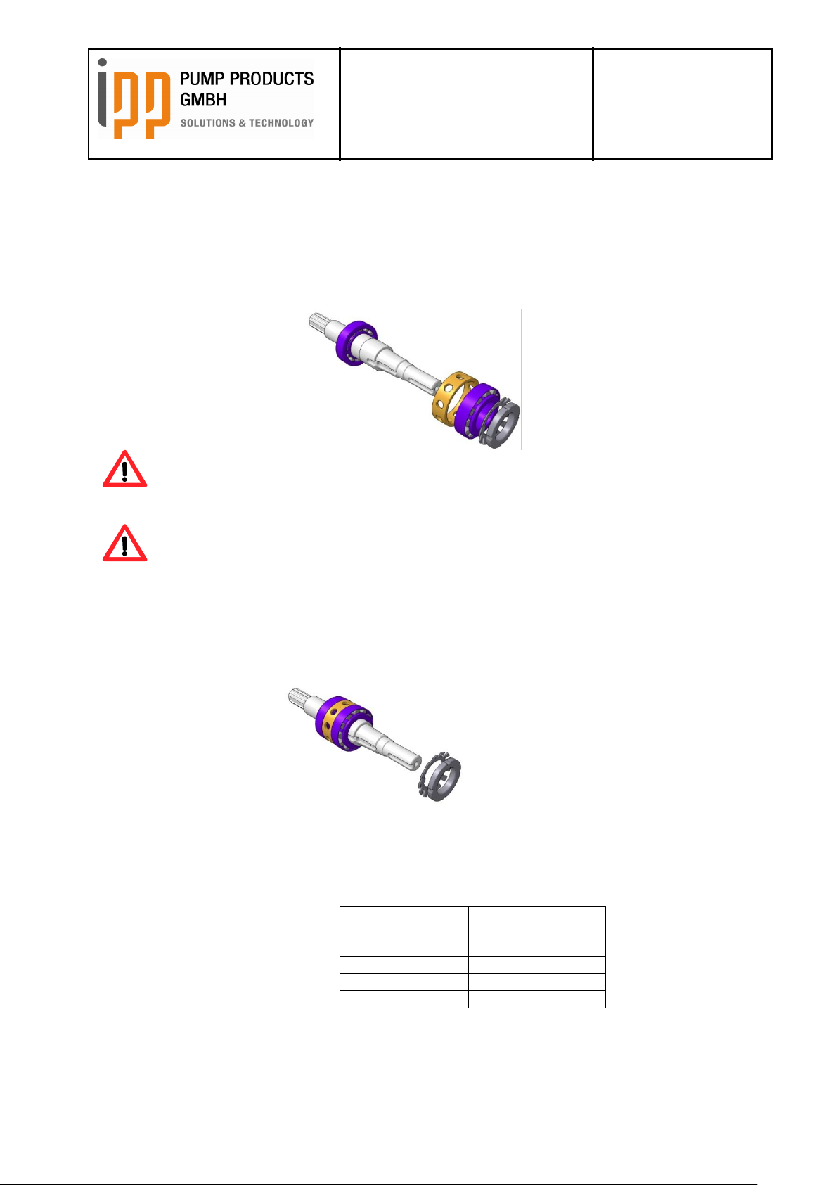
13.8.1.3 Double mechanical seals
First place the rotating sliding ring of the atmosphere side onto the shaft. We recommend inserting the
o-ring into the sliding ring first. Grease the o-ring with an appropriate lubricant. Turn the shafts to 3
o’clock position so that the cylindrical pins for the rotating-lock can be seen in the leakage slots. Insert
the sliding ring so that the cylindrical pins fit into the driving grooves. Two of the supplied locking
blocks can be of assistance, see picture.
Doc. No. 0179 – status 03/2017
Page 43

Operating instructions
iLobe
Rotary Lobe Pump
Date: 15.03.2017
Page 43 of 63
Doc. No. 0179
Est: D. Lünnemann /
W. Stein
Now install the mechanical seal housing. Insert the wave spring as well as the o-ring for the fixed
sliding ring of the atmosphere side. Ensure that the wave spring lies between the two rows of
cylindrical pins for the rotating locking. Grease the o-ring by means of an appropriate lubricant. When
inserting the sliding ring the cylindrical pins of the atmosphere side must fit into the driving grooves of
the sliding ring.
Install the static o-ring at the outside diameter of the mechanical seal housing. Don’t overstretch the oring. Grease the o-ring by means of an appropriate lubricant.
Doc. No. 0179 – status 03/2017
Page 44
Operating instructions
iLobe
Rotary Lobe Pump
Date: 15.03.2017
Page 44 of 63
Doc. No. 0179
Est: D. Lünnemann /
W. Stein
Insert the mechanical seal housing into the pump case.
NOTE
First the sliding surfaces of both atmosphere side sliding rings must be cleaned and free of grease.
The pins of the rotating locking must fit into the grooves provided for that. These are in one line to the
leakage slots.
Now insert the fixed sliding rings together with the o-ring. We recommend inserting the o-ring to
the sliding ring first. Ensure that the cylindrical pins of the mechanical seal housing fit into the
driving grooves of the sliding rings. Attention: Grease the o-rings by means of an appropriate
lubricant.
Now insert the rotating sliding rings with the installed o-rings into the rotors. Ensure that the pins fit into
the grooves of the rotor.
Attention: Grease the o-rings by means of an appropriate lubricant.
Clean the sliding surfaces so that they are free of grease and insert them into the rotors.
Doc. No. 0179 – status 03/2017
Page 45
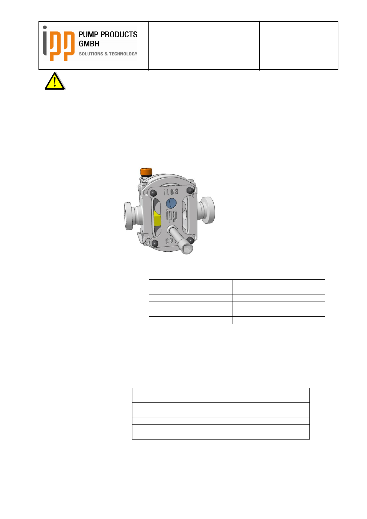
Operating instructions
iLobe
Rotary Lobe Pump
Date: 15.03.2017
Page 45 of 63
Doc. No. 0179
Est: D. Lünnemann /
W. Stein
Type
Torque
iL42
25 Nm
iL55
36 Nm
iL63
50 Nm
iL85
70 Nm
iL115
150 Nm
Type
Quattro lobe-Rotors
Mesh clearance
Biwing-Rotors
Mesh clearance
iL42
0,08-0,15
4,2 – 6,0 mm
iL55
0,09 – 0,16 mm
7,4 – 8,0 mm
iL63
0,12 – 0,20 mm
11,8 – 12,1 mm
iL85
0,12 – 0,18 mm
14,4 – 15,5 mm
iL115
0,15 – 0,25 mm
22,0 – 23,4 mm
ATTENTION
No excessive force is needed to install the mechanical seal provided that all parts are engaged
to each other appropriately. Check the spring functioning before installing the rotors.
Now install the rotors. Some rotors are stamped and should be kept with their respective shafts.
Check the wave spring functioning of the mechanical seal again by pushing the rotors against the
seat. The wave spring must push back the rotors.
Now install the slightly greased o-rings and the rotor screw.
We recommend using the auxiliary tool in order to avoid damaging the rotor screw even with high
tightening torques.
13.9 Tightening Torques:
The rotor to be tightened must be blocked before. As the gear wheels are not tightened yet, they don’t
transmit a turning moment.
Now tighten the rotors by means of a torque wrench.
Now adjust the timing between the rotors. For this purpose fix the gear wheel in the position where the
rotors don’t touch each other when turning left or right.
A feeler gauge for Quattro-lobe rotors and a slide gauge for Biwing-rotors are required.
Doc. No. 0179 – status 03/2017
Page 46

Operating instructions
iLobe
Rotary Lobe Pump
Date: 15.03.2017
Page 46 of 63
Doc. No. 0179
Est: D. Lünnemann /
W. Stein
iL42
iL55
iL63
iL85
iL115
Radial max
[mm]
0,12
0,14
0,18
0,165
0,225
Radial min
[mm]
0,10
0,11
0,12
0,135
0,195
Axial front max
[mm]
0,11
0,12
0,18
0,16
0,186
Axial front min
[mm]
0,09
0,10
0,12
0,135
0,165
Axial rear max
[mm]
0,11
0,12
0,18
0,185
0,215
Axial rear min
[mm]
0,09
0,10
0,12
0,16
0,194
Mesh clearance max
[mm]
0,15
0,18
0,2
0,18
0,25
Mesh clearance min
[mm]
0,08
0,09
0,12
0,12
0,2
Mesh distance max
[mm]
6,0
8,0
12,5
15,5
23,4
Mesh distance min
[mm]
4,2
7,4
11,5
14,5
22,0
Insert the flat gasket and ensure clean and even surfaces without residues.
Install the gear box cover on the bearing housing. Be careful when passing through the shaft in order
not to damage the radial shaft seals. Slight greasing could be helpful.
Before tightening, ensure that the radial shaft seal is concentric to the shaft. Now fill in oil as described
in chapter 10.14.
Before installing the pump cover, check the pump clearances in order to ensure the contactless
running of the rotors. A feeler gauge and a depth gauge are required!
The standard clearances are as follows:
The values can vary in case of electro polished or specially adjusted pumps.
Install the pump case cover.
ATTENTION
Don’t stretch or overstretch the o-ring resp. the profile gasket, otherwise the gasket must be replaced
before installing the pump case cover.
14 Decommissioning
14.1 Disassembly
See chapter 13.5 for disassembling the pump.
14.2 Storage
See paragraph 10.3 Storage Conditions.
Doc. No. 0179 – status 03/2017
Page 47
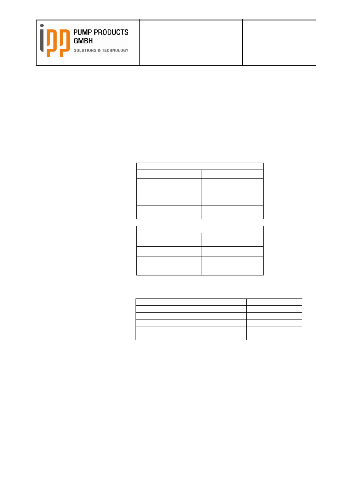
Operating instructions
iLobe
Rotary Lobe Pump
Date: 15.03.2017
Page 47 of 63
Doc. No. 0179
Est: D. Lünnemann /
W. Stein
Example of recommended oils
Brand
Type
Shell
Cassida Fluid HF 68,
NSF H1
PETRO-CANADA
Purity FG AW
Hydraulic 68, NSF H1
Klüber
4UH1-68N, NSF H1
(synthetisch)
Recommended characteristics
Environment
temperature
Viscosity
-18 °C to 0 °C
VG 68
0 °C to 30 °C
VG 68
30 °C to 150 °C
VG 220
Horizontal
Vertical
iL42
0,2 Liter
0,25 Liter
iL55
0,25 Liter
0,26 Liter
iL63
0,27 Liter
0,29 Liter
iL85
0,9 Liter
0,8 Liter
iL115
2,25 Liter
2,0 Liter
14.3 Disposal
If the pump should be scrapped the following points must be observed:
Clean the pump case inside if there could be residues of the pumped liquid.
Drain the oil completely of the gear box.
Offer the old pump to a company specialized in metal scraping.
15 Technical data
15.1 Oil types
The following types of oil are recommended for the gear box:
15.2 Oil quantities
Doc. No. 0179 – status 03/2017
Page 48

Operating instructions
iLobe
Rotary Lobe Pump
Date: 15.03.2017
Page 48 of 63
Doc. No. 0179
Est: D. Lünnemann /
W. Stein
Pos.
Description
Quantity
Pos.
Description
Quantity
1.5
Mechanical seal housing
2
4.5
Shaft nut
2
1.10
Spacer bushing I
2
4.6
Tab washer
2
1.10.1
Driving pins spacer bushing
6
4.8
Allen screw bearing flange
12
1.10.2
O-Ring spacer bushing front side
2
4.9
Allen screw bearing case
4
1.10.3
O-Ring spacer bushing radial
2
4.10
Frontal radial shaft seal
2
2.1
Driving shaft
1
5.1
Gear box cover
1
2.2
Driven shaft
1
5.2
Locking plug
1
2.3
Rotor
2
5.4
Oil dipstick
1
3.1
Gear wheel driven shaft helical gearing
1
5.5
Flat gasket gear box cover
1
3.2
Gear ring driving shaft, helical gearing
1
5.6
Allen screw
4
3.3
Clamping ring gearing ring
1
5.8
Rear radial shaft seal
1
3.4
Centre bush
1
5.9
Retaining ring
1
3.4.1
O-Ring centre bush
1
6.1
Pump foot
2
3.5
Allen screw
10
6.2
Hexagonal screw
4
3.6
Shaft nut
2
7.1
Pump case
1
3.7
Tab washer
2
8.0
Rotor screw
2
3.8
Feather key
2
8.1
O-Ring rotor screw
2
3.9
Feather key, drive pin
1
9.1
Pump case cover
1
4.1
Bearing case
1
9.2
O-ring pump case cover
1
4.2
Bearing flange
2
9.3
Stud screw
4
4.3
Spacer bush
2
9.4
Cap nut
4
4.4
Taper roller bearing
4
16 Cross-sectional drawing
17 Parts list
Doc. No. 0179 – status 03/2017
Page 49
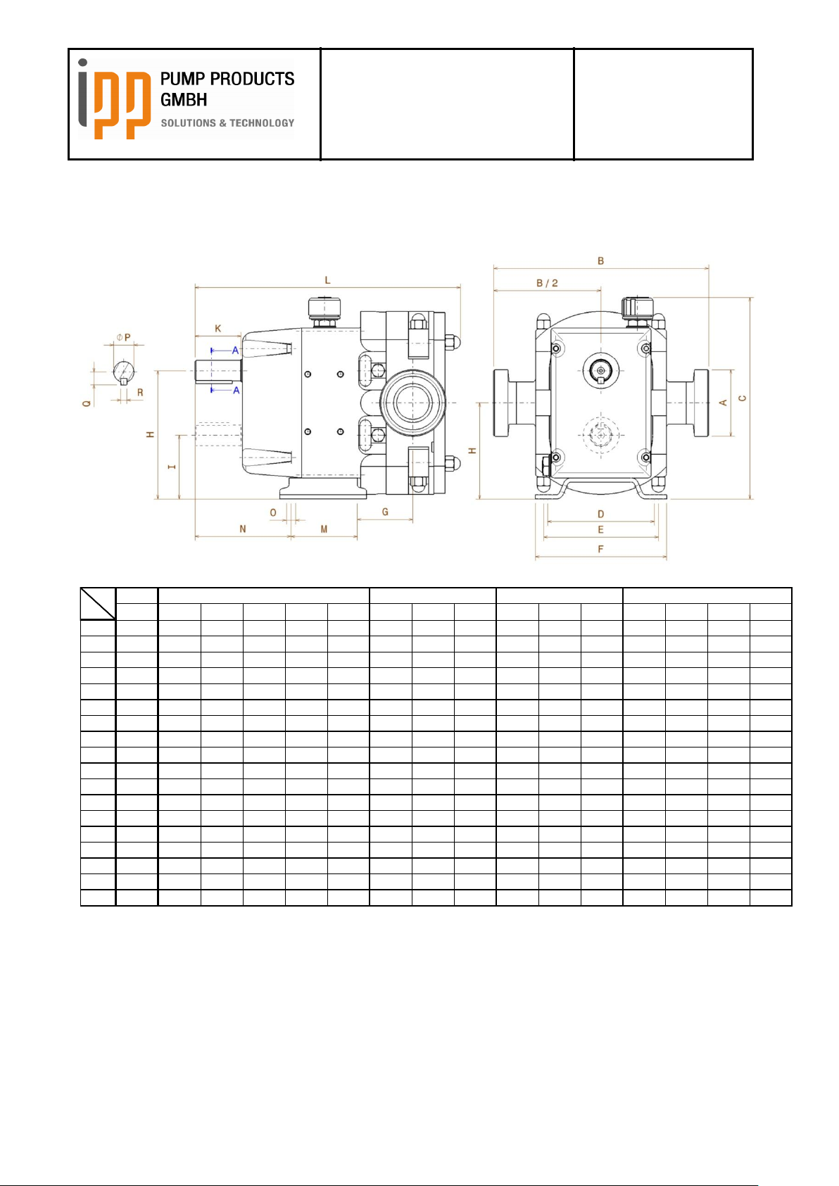
Operating instructions
iLobe
Rotary Lobe Pump
Date: 15.03.2017
Page 49 of 63
Doc. No. 0179
Est: D. Lünnemann /
W. Stein
iL42
i sx/sxx s i li l s i l s i l s si i l
A DN 25 DN 15 DN20 DN25 DN 32 DN 40 DN 40 DN 40 DN 40 DN 40 DN 50 DN 65 DN 50 DN 65 DN 80 DN 100
B 157 177 177 177 176 174 210 210 210 234 232 236 308 312 312 322
C 134 182 182 182 182 182 196 196 196 237 237 237 319 319 319 319
D 105 106 106 106 106 106 104 104 104 155 155 155 195 195 195 195
E 105 110 110 110 110 110 112 112 112 160 160 160 201 201 201 201
F 125 130 130 130 130 130 128 128 128 180 180 180 220 220 220 220
G 49,5 31 34,5 38,5 42,5 48,5 55 55 67 67,2 73,7 76,2 75,5 79,75 90,3 102,3
H 58,5 90,5 90,5 90,5 90,5 90,5 93,5 93,5 93,5 123 123 123 164 164 164 164
I 37 63 63 63 63 63 62 62 62 80,5 80,5 80,5 106,5 106,5 106,5 106,5
J 80 118 118 118 118 118 125 125 125 165,5 165,5 165,5 221,5 221,5 221,5 221,5
K 29 29 29 29 29 29 45 45 45 46 46 46 70 70 70 70
L 210 213 218 225 233,5 244 260 260 277 335 346 357 455 466 484 506
M 65 55 55 55 55 55 65 65 65 86 86 86 96 96 96 96
N 59,5 90,5 90,5 90,5 90,5 90,5 94 94 94 126 126 126 211 211 211 211
O 9 9 9 9 9 9 9 9 9 11 11 11 11 11 11 11
P 14 15 15 15 15 15 20 20 20 25 25 25 40 40 40 40
Q 9 9,5 9,5 9,5 9,5 9,5 12,5 12,5 12,5 15,5 15,5 15,5 23 23 23 23
R 5 5 5 5 5 5 6 6 6 8 8 8 12 12 12 12
iL63
Typ
Pos
iL115
iL85
iL55
18 Dimensions
18.1 Horizontal execution
Doc. No. 0179 – status 03/2017
Page 50
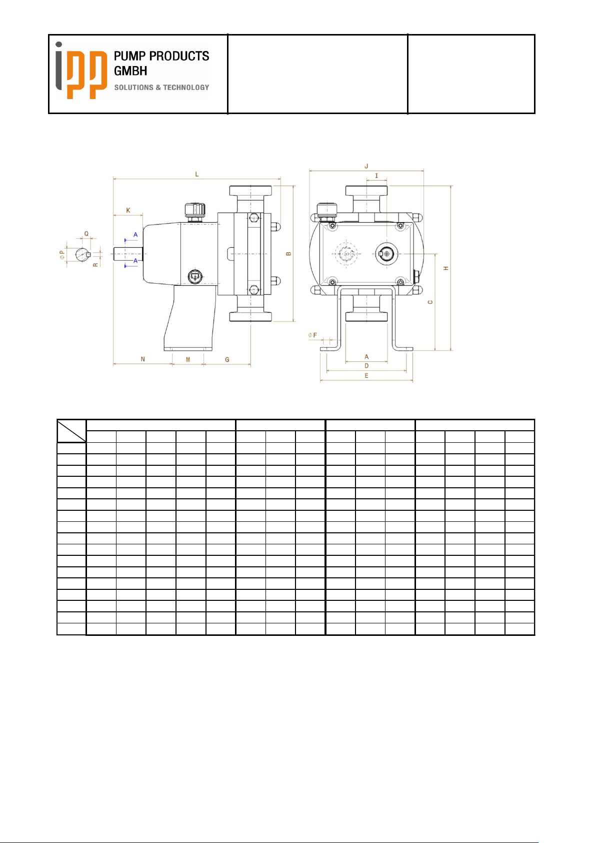
Operating instructions
iLobe
Rotary Lobe Pump
Date: 15.03.2017
Page 50 of 63
Doc. No. 0179
Est: D. Lünnemann /
W. Stein
sx/sxx s i li l s i l s i l s si i l
A DN 15 DN 20 DN 25 DN 32 DN 40 DN 40 DN 40 DN 40 DN 40 DN 50 DN 65 DN 50 DN 65 DN 80 DN 100
B 177 177 177 176 174 210 210 210 234 232 236 308 312 312 322
C 118 118 118 118 118 150 150 150 165,5 165,5 165,5 145 145 145 145
D 124 124 124 124 124 124 124 124 156 156 156 196 196 196 196
E 144 144 144 144 144 144 144 144 180 180 180 220 220 220 220
F 10 10 10 10 10 10 10 10 11 11 11 11 11 11 11
G 48,5 52,5 56 60 66 73 73 87 84,7 91,2 93,7 68,7 73 83,5 95,5
H 206,5 206,5 206,5 206 205 255 255 255 282,5 281,5 283,5 299 301 301 306
I 27,5 27,5 27,5 27,5 27,5 31,5 31,5 31,5 42,5 42,5 42,5 57,5 57,5 57,5 57,5
J 162 162 162 162 162 178 178 178 218 218 218 298 298 298 298
K 31 31 31 31 31 45 45 45 46 46 46 70 70 70 70
L 213 213 213 213 213 260 260 277 335 346 357 455 466 484 506
M 45 45 45 45 45 49 49 49 51 51 51 96 96 96 96
N 83 83 83 83 83 91,5 91,5 89,5 143,5 143,5 143,5 216 216 216 216
P 15 15 15 15 15 20 20 20 25 25 25 40 40 40 40
Q 9,5 9,5 9,5 9,5 9,5 12,5 12,5 12,5 15,5 15,5 15,5 23 23 23 23
R 5 5 5 5 5 6 6 6 8 8 8 12 12 12 12
iL63
Typ
Pos
iL115
iL85
iL55
18.2 Vertical execution
Doc. No. 0179 – status 03/2017
Page 51
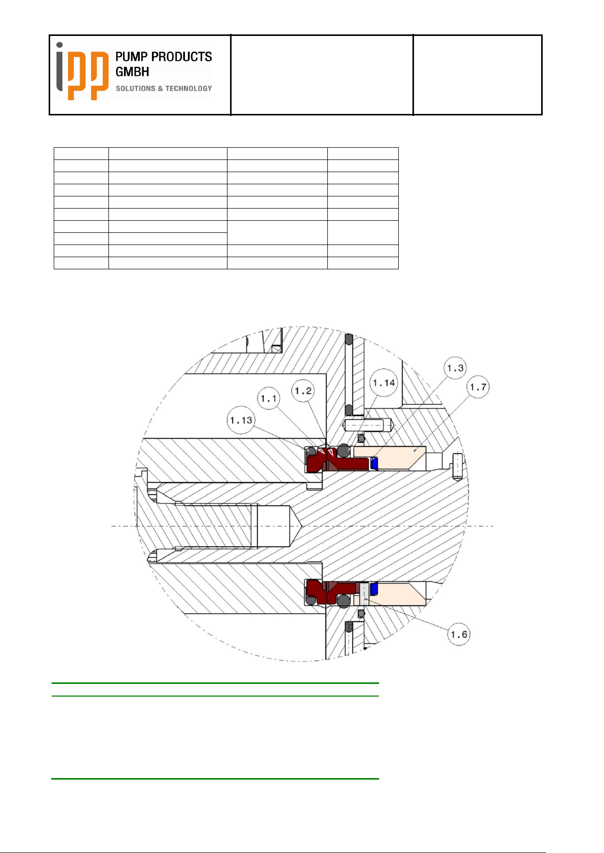
Operating instructions
iLobe
Rotary Lobe Pump
Date: 15.03.2017
Page 51 of 63
Doc. No. 0179
Est: D. Lünnemann /
W. Stein
Pos. No.
Description
Materials:
Material no.
9.1
Pump case cover
Stainless steel
1.4404
8.0
Rotor screw
Stainless steel
1.4404
4.1
Bearing housing
ST52
3.2
Gear ring
34CrNiMo6
1.6582
3.1
Gear wheel
42CrMo4
1.7225
2.1
Driving shaft
X-2 CrNiMoN 22-5-3
1.4462
2.2
Driven shaft
7.1
Pump case
Stainless steel
1.4404
2.3
Rotor
Stainless steel
1.4404
Pos.
Description
Quantity
1.1
Rotary Seal Face, Product Seal
2
1.2
Stationary Seal Face, Product Seal
2
1.3
Wave Spring
2
1.6
Anti-Rotation Pins Seal Housing, Single Mech. Seal
4
1.7
Seal Housing Single Mecanical Seal
2
1.13
O-Ring Rotary Seal Face, Product Seal
2
1.14
O-Ring Stationary Seal Face, Product Seal
2
18.3 Material specifications
18.3.1 Shaft seals
18.3.1.1 Single mechanical seals
Doc. No. 0179 – status 03/2017
Page 52

Operating instructions
iLobe
Rotary Lobe Pump
Date: 15.03.2017
Page 52 of 63
Doc. No. 0179
Est: D. Lünnemann /
W. Stein
Pos.
Description
Quantity
1.1
Rotary Seal Face, Product Seal
2
1.2
Stationary Seal Face, Product Seal
2
1.3
Wave Spring
2
1.5
Seal Housing Double Mecanical Seal
2
1.6
Anti-Rotation Pins, Seal Housing, Double Mech. Seal
8
1.11
Stationary Seal Face, Atmosphere Seal
2
1.12
Rotary Seal Face, Atmosphere Seal
2
1.13
O-Ring Rotary Seal Face, Product Seal
2
1.14
O-Ring Stationary Seal Face, Product Seal
2
1.15
O-Ring Stationary Seal Face, Atmosphere Seal
2
1.16
O-Ring Rotary Seal Face, Atmosphere Seal
2
1.17
O-Ring, Seal Housing
2
18.3.1.2 Double mechanical seal
Doc. No. 0179 – status 03/2017
Page 53

Operating instructions
iLobe
Rotary Lobe Pump
Date: 15.03.2017
Page 53 of 63
Doc. No. 0179
Est: D. Lünnemann /
W. Stein
Pos.
Description
Quantity
1.21
Radial shaft seal
2
1.22
Shaft protection bush
2
1.23
O-ring
2
1.24
Ejection bush
2
18.3.1.3 Lip seal
19 Pressure relief valves
19.1 Effect, purpose and hygienic suitability
In order to protect the pump and the factory there are pressure relief valves available for the integration into
the pump cover. The pressure relief valves are available in two versions, spring loaded or pressure loaded.
At a certain pressure in the pump these pressure relief valves react and cause a short-circuit between the
inlet and outlet port of the pump. Thus the rotary lobe pump as displacement pump is protected against
overpressure. The pressure relief valves are also suitable for hygienic operation as the discharge room
which means the short-circuit between inlet and outlet, is being re-closed completely.
Doc. No. 0179 – status 03/2017
Page 54
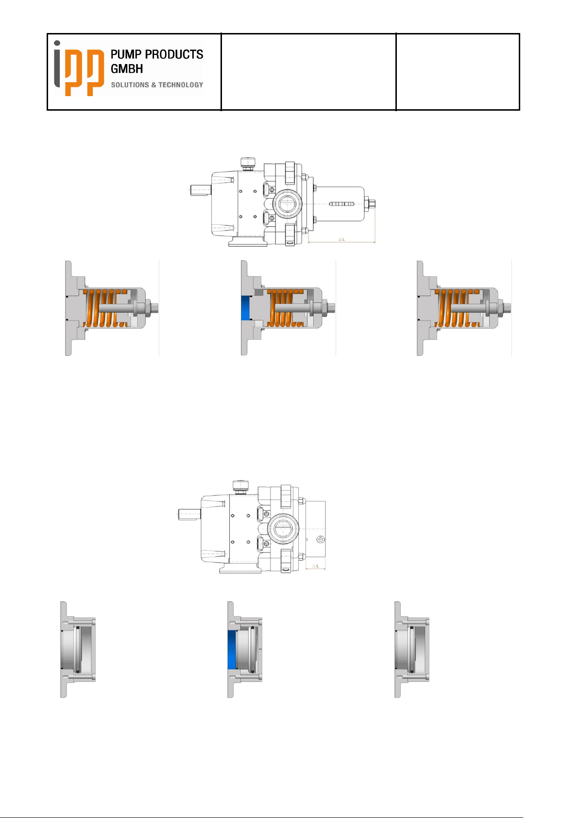
Operating instructions
iLobe
Rotary Lobe Pump
Date: 15.03.2017
Page 54 of 63
Doc. No. 0179
Est: D. Lünnemann /
W. Stein
closed
closed
opened
closed
closed
opened
19.1.1 Pressure relief valve integrated into the pump cover, spring loaded
19.1.2 Pressure relief valve integrated into the pump cover, pressure loaded and controlled by
compressed air
Doc. No. 0179 – status 03/2017
Page 55

Operating instructions
iLobe
Rotary Lobe Pump
Date: 15.03.2017
Page 55 of 63
Doc. No. 0179
Est: D. Lünnemann /
W. Stein
19.2 Adjustment
The hydraulically loaded surface of the pressure relief valve corresponds to app. ½ of the valve piston
surface when the pump is running. With the pump stationary the complete surface is loaded. The reaction
pressure of the valve cannot be pre-adjusted. The adjustment pressure depends on the individual product
characteristics and the respective operating conditions.
The adjustment is done as follows:
Install a pressure gauge if possible directly at the outlet port of the pump. As far as possible let the pump run
discharged respectively without nameable resistances in the factory installation. Simulate a resistance for
example by slowly closing one blocking valve and observe the pressure gauge. Adjust the desired reaction
pressure by charging the pressure relief valve step by step and closing the blocking valve. The reaction
pressure is reached when the pressure gauge stops rising when the blocking valve is completely closed.
The spring loaded pressure relief valve is pre-loaded by turning the valve rod anti-clockwise.
The pressure loaded pressure relief valve is being pre-loaded for example by means of a pressure reducer.
When supplied to the customer the pressure relief valves are always relaxed.
19.3 Maintenance and lubrication
The lubrication points at the spring loaded pressure relief valve are at the valve rod at the contact surfaced to
the valve housing and in the thread.
At a pressure loaded pressure relief valve the o-rings must be provide with an appropriate lubricant.
Doc. No. 0179 – status 03/2017
Page 56
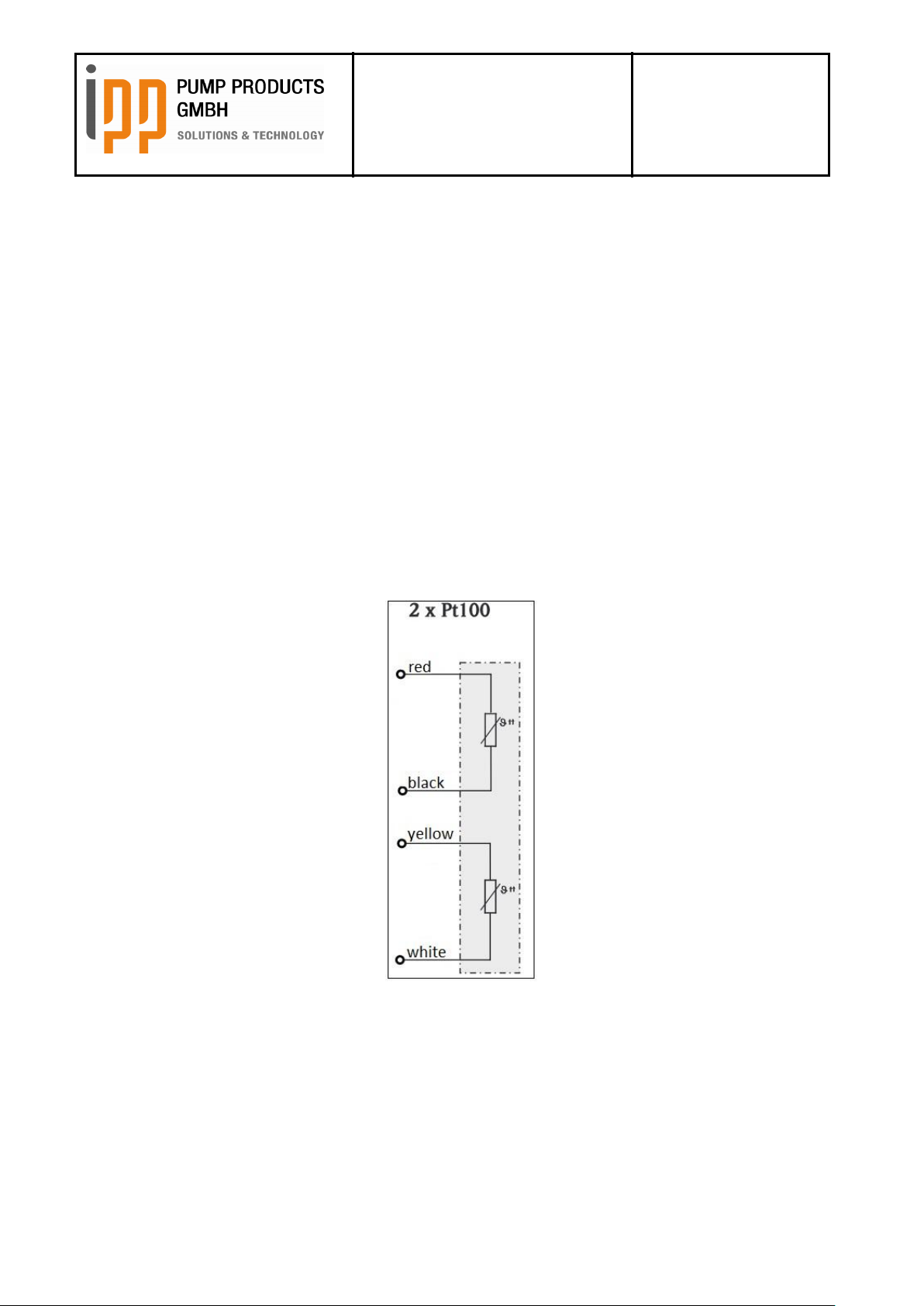
Operating instructions
iLobe
Rotary Lobe Pump
Date: 15.03.2017
Page 56 of 63
Doc. No. 0179
Est: D. Lünnemann /
W. Stein
19.4 Pressure relief valve with built-in temperature sensor
Generally, positive displacement pumps must be protected against excessive overpressure.
Excessively high overpressure might be caused by an obstruction in the discharge line, by solidifying or
cooling of the pumped fluid, by modification of the pumped fluid or by wrong pre-setting of the speed.
A protection against overpressure must be provided either on site by an external pressure relief valve, e.g.
with tank return system or by a pressure relief valve built into the pump cover. Pressure relief valves built into
the pump cover must be adjusted to the response pressure values which have to be fixed by the customer.
After reaction, correctly adjusted pressure relief valves release the pump internal return flow from the
discharge side to the suction side. The fluid displaced by the pump elements, circulates in the pump so that
the major part of the frictional heat is not being discharged anymore thus causing an uncontrolled increase of
temperature in the pump. The temperature sensor integrated to the pump cover is used for a safety-related
shutdown of the pump.
The shutdown temperature must be fixed by the user of the pump. We recommend a shutdown temperature
of 10 – 20 K above the maximum operating temperature.
The built-in temperature sensor is a resistance temperature detector with two PT 100 measuring resistors in
a 2-wire configuration.
As the sensor is a resistance sensor, for the evaluation an electronic temperature transmitter is required
which supplies power to the sensor and measures and evaluates the variable voltage drop.
By using two independent measuring resistors both mechanically and chemically caused temperature
variations of a sensor element can be recognized and reported by the transmitter. For this purpose the
temperature transmitter must record the independent measured values of both measuring resistances,
evaluate and compare them.
Doc. No. 0179 – status 03/2017
Page 57

Operating instructions
iLobe
Rotary Lobe Pump
Date: 15.03.2017
Page 57 of 63
Doc. No. 0179
Est: D. Lünnemann /
W. Stein
The recognition of changes of sensor measured values caused by an error is of particular importance for a
later SIL consideration. The corresponding performance level respectively SIL results from the risk analysis
(risk graph), which must be issued respectively stipulated by the user of the pump.
The integration and calibration of the temperature sensor is explicitly done by the customer. Also the correct
setting of the pressure relief valve is done by the customer.
The maximum operating pressure values for the setting of the pressure relief valve and the maximum
operating temperatures can be looked up in the commercial documents.
Doc. No. 0179 – status 03/2017
Page 58

Operating instructions
iLobe
Rotary Lobe Pump
Date: 15.03.2017
Page 58 of 63
Doc. No. 0179
Est: D. Lünnemann /
W. Stein
Pos.
Description
Quantity
9.2
O-Ring pump case cover
1
9.10.1
Valve housing
1
9.10.2
Pump cover for pressure relief
valve
1
9.10.3
Valve rod
1
9.10.4
Counter nut
1
9.10.5
Pressure plate
1
9.10.6
Valve spring
1
9.10.7
Valve piston
1
9.10.8
O-ring pressure relief valve /
spring
1
9.10.9
POM-washer
1
9.10.10
Hexagonal screw
4
9.10.11
Washer
4
Pos.
Description
Quantity
9.2
O-Ring pump case cover
1
9.11.1
Valve cover
1
9.11.2
Pump cover for pressure
relief valve
1
9.11.3
Control piston
1
9.11.4
Allen screw
8
9.11.5
O-ring valve cover
1
9.11.6
O-ring control piston
1
19.5 Parts list
19.5.1 Spring loaded pressure relief valves
19.5.2 Pressure relief valve pressure loaded and controlled by compressed air
Doc. No. 0179 – status 03/2017
Page 59

Operating instructions
iLobe
Rotary Lobe Pump
Date: 15.03.2017
Page 59 of 63
Doc. No. 0179
Est: D. Lünnemann /
W. Stein
Pos.
Description
Quantity
9.2
O-Ring seal for pump case
cover
1
9.11.1
Valve cover
1
9.11.2
Pump housing cover for
pressure relief valve
1
9.11.3
Guiding, valve piston
1
9.11.4
Control plate
1
9.11.5
Distance plate
1
9.11.6
Control plate
1
9.11.7
Valve piston
1
9.11.8
Allen screw
1
9.11.9
Allen screw
8
9.11.10
O-Ring seal for control plate
1
9.11.11
O-Ring seal for control
housing
1
9.11.12
O-Ring seal for guiding for
valve pistion
2
9.11.13
O-Ring seal for guiding
valve piston / control plate
1
9.11.14
O-Ring seal for valve piston
1
19.5.3 2-Way Pressure relief valve pressure loaded and controlled by compressed air
20 Heating / heat exchange
20.1 Principle
The series iLobe can be fitted with a heatable pump case.
The heat exchange surfaces also permit the cooling of the pump.
Thus the surface temperatures in the pump can be adapted. The heat exchange surfaces are not
dimensioned for cooling or heating the system.
Doc. No. 0179 – status 03/2017
Page 60
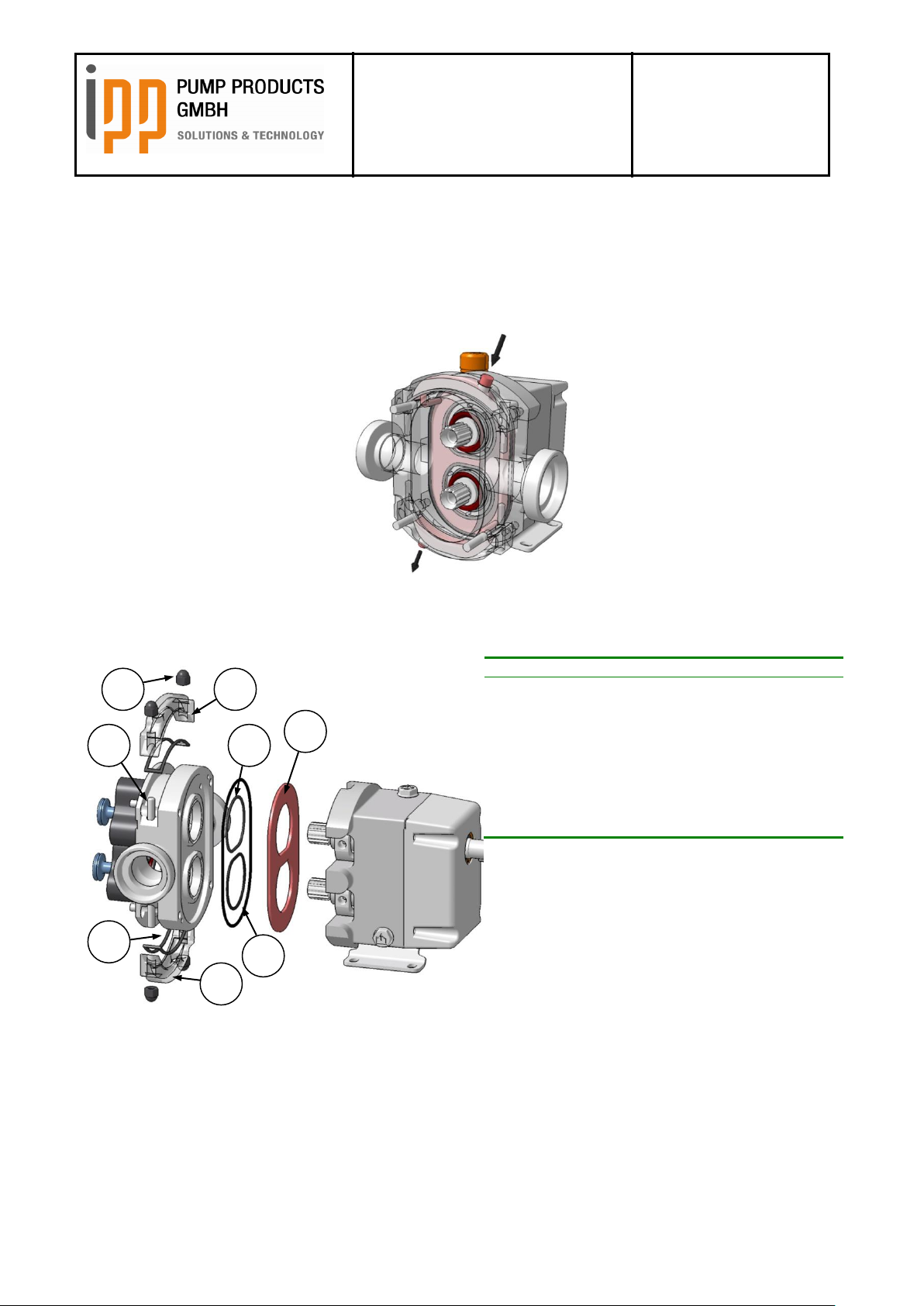
Operating instructions
iLobe
Rotary Lobe Pump
Date: 15.03.2017
Page 60 of 63
Doc. No. 0179
Est: D. Lünnemann /
W. Stein
Pos.
Description
Quantity
7.2.1
Heating pump cover top
1
7.2.2
Heating pump cover bottom
1
7.3
Heating plate
1
7.3.1
O-Ring Heating plate large
1
7.3.2
O-Ring Heating plate small
2
7.4
Stud Screw
4
7.5
Cap nut
4
7.6
Gasket heating pump cover
2
7.2.1
7.2.2
7.3
7.4
7.3.1
7.3.2
7.5
7.6
20.2 Heatable pump case with integrated heat channels IHCh RC
In order to improve the heat exchange any iLobe rotary lobe pump can be fitted optionally with integrated
heat channels in the pump case. This option can only be implemented later if the pump has been prepared
for heating.
The heating can be done through different heating transfer media. The maximum pressure is app. 3,5bar
overpressure.
The flow direction of the heating transfer media is variable.
Doc. No. 0179 – status 03/2017
Page 61

Operating instructions
iLobe
Rotary Lobe Pump
Date: 15.03.2017
Page 61 of 63
Doc. No. 0179
Est: D. Lünnemann /
W. Stein
21 Trouble shooting
A malfunction in a pump system may have various causes. The malfunction is not always necessarily in the
pump itself, but an also be caused by a malfunction in the piping system or in another fitting in the system. If
the real operating conditions deviate too much from the specifications according to which the pump was
purchased, this might also cause malfunctioning. Therefore the following points should be checked first:
Has the pump been installed correctly?
Are the operating conditions still in accordance with the original specifications?
Are the further fittings in the pipe system functioning correctly?
In general the following malfunctions can be observed at a pump:
Pump gives no liquid
Pump gives irregular liquid flow
Capacity too low
Pump overheats
Motor overheats
Excessive rotor wear
Excessive wear of the shaft seals
Pump vibrates excessively or makes too much noise
Pump stops
Pump stops during start-up
The table on the next page shows possible cases and solutions for the malfunctions mentioned above:
Doc. No. 0179 – status 03/2017
Page 62

Operating instructions
iLobe
Rotary Lobe Pump
Date: 15.03.2017
Page 62 of 63
Doc. No. 0179
Est: D. Lünnemann /
W. Stein
Fault
Cause
Action
1 2 3 4 5 6 7 8 9
10
*
Wrong direction of
rotation
Change direction of rotation of
motor
*
Pump is not filled with
liquid
Vent suction line and rotor case and
prime rotor case with liquid
* * * * Insufficient NPSHA
Enlarge diameter of suction line or
simplify suction line and make it
shorter, or reduce speed and
product temperature
* * *
Creation of steam in the
suction line
* * *
Air entering into the
suction line
Check the connections
* * * * Gas in the suction line
Vent suction line / pump casing
* * * Insufficient static head
Increase liquid level to enlarge
static head
* * *
*
Product viscosity is too
high
Reduce the speed / increase the
product temperature
*
Product viscosity is too
low
Increase speed / lower the product
temperature
* * * *
*
Product temperature
too high
Cool the product / pump casing
*
*
Product temperature
too low
Heat the product / rotor case
* * * *
Foreign particles in the
product
Clean the system / place a filter at
suction side
* * * * * *
*
Pressure at pump
discharge is too high
Check the piping for obstructions /
simplify the discharge line
* * * * *
Pump case distorted by
piping
Check alignment / support the
piping
* * Speed too high
Reduce the speed
* Speed too low
Increase the speed
* * * * * * Insufficient flushing
Increase flushing pressure /
capacity
* * * * * *
*
Worn bearings / timing
gears
Replace worn parts
*
Pressure relief valves
reacts
Check the discharge for any
obstructions, closed valves or
further reasons for resistance
Doc. No. 0179 – status 03/2017
Page 63

Operating instructions
iLobe
Rotary Lobe Pump
Date: 15.03.2017
Page 63 of 63
Doc. No. 0179
Est: D. Lünnemann /
W. Stein
22 Index
Assembly of the pump unit .............................................................................................................................. 19
Connection of the pipes ................................................................................................................................... 21
Coupling ........................................................................................................................................................... 19
Decommissioning ............................................................................................................................................ 46
Dimensions
Horizontal Port Position................................................................................................................................ 49
Disassembly ............................................................................................................................ 30, 32, 33, 35, 46
Functioning – description ................................................................................................................................. 12
Heating............................................................................................................................................................. 57
Installation Dimensions .................................................................................................................................... 17
Lip seal....................................................................................................................................................... 13, 53
Maintenance .............................................................................................................................................. 30, 55
Manufacturer ................................................................................................................................................ 7, 11
Material specification ....................................................................................................................................... 51
Mechanical seals ................................................................................................................................. 40, 42, 51
Oil types ........................................................................................................................................................... 47
Operating instructions
How to consult and storage ........................................................................................................................... 5
Part List
Double mechanical seal ............................................................................................................................... 42
Lip seal ................................................................................................................................................... 13, 53
Pressure Relief Valve Pressure loaded ....................................................................................................... 56
Pressure Relief Valve spring loaded ............................................................................................................ 56
Single mechanical seal .................................................................................................................... 40, 42, 51
Pressure Relief Valve
Maintenance and lubrication ........................................................................................................................ 55
Pressure relief valves ...................................................................................................................................... 19
Pump
storage ......................................................................................................................................................... 46
Pump case ....................................................................................................................................................... 34
Pump components ........................................................................................................................................... 14
Pump drainage ................................................................................................................................................ 31
Range of products ........................................................................................................................................... 12
Rotor ................................................................................................................................................................ 31
Rotor dummies ................................................................................................................................................ 28
Shaft seals ............................................................................................................................... 13, 40, 42, 51, 53
flushing ......................................................................................................................................................... 21
Shaft Seals
Double mechanical seal ................................................................................................................... 13, 42, 52
Staff .................................................................................................................................................................. 11
Start-up ............................................................................................................................................................ 29
Storage ............................................................................................................................................................ 46
Symbols ............................................................................................................................................................. 6
Tags ................................................................................................................................................................... 6
Torques ............................................................................................................................................................ 45
Transport ................................................................................................................................................... 10, 15
Lifting ...................................................................................................................................................... 32, 35
Transport and receipt of goods ........................................................................................................................ 10
Trouble shooting .............................................................................................................................................. 57
Use of the pump ................................................................................................................................................ 9
Warranty .......................................................................................................................................................... 10
Doc. No. 0179 – status 03/2017
 Loading...