

IP Power 9820 User Manual

Firmware Version: 1.0B
Date Released: SEP. 2014
IP Power 9820
User Manual
- 1 -

Warning: Any changes made to this equipment without permission may cause damages to the device!
IMPORTANT NOTICE
1. IP Power 9820 was designed for indoor use, we carry no responsibility for possible damages
caused by outdoor use, especially in the rain.
2. Please use the power adapter provided by the dealer, we carry no responsibility for the
possible damage from using power adapters not provided by us .
4. Do not shake the IP Power 9820 in any fashion
5. Please contact the dealer If IP Power 9820 is not working properly.
Copyright © 2014 All rights reserved. No part of this publication may be reproduced, stored in a
retrieval system, or transmitted in any form or by any means, electronic, mechanical,
photocopying, recording or otherwise, without the prior written consent of us.
All trademarks and products mentioned in this document are the properties of us.
- 2 -

Table of Content
WELCOME ........................................................................................................... 5
Introduction .................................................................................................................................................. 5
PRODUCT OVERVIEW ........................................................................................ 6
Features ......................................................................................................................................................... 6
Specification .................................................................................................................................................. 7
Minimum System Requirements ................................................................................................................. 7
Package Contents ......................................................................................................................................... 8
INTERFACE DESCRIPTION ................................................................................ 9
Front View..................................................................................................................................................... 9
Rear View .....................................................................................................................................................11
From Left side to Right side ....................................................................................................................11
SETTING UP USER DEVICE ............................................................................. 12
Before we Start ............................................................................................................................................12
Hardware Connection .................................................................................................................................12
Software Installation ...................................................................................................................................12
Installing Software ....................................................................................................................................13
Connection by WiFi- WPS ( WiFi Protection Service ) ...........................................................................14
Connection first by LAN –Network cable then setup for WiFi connection ..............................................16
Internet Setup ................................ ................................ ................................................................ ............22
Using IP Server .........................................................................................................................................22
WEB INTERFACE .............................................................................................. 24
Connect to user Device ...............................................................................................................................24
Device name .............................................................................................................................................26
Display or Hide the left setting section : ...................................................................................................26
Information : .............................................................................................................................................27
IO Control : ...............................................................................................................................................28
Network : ..................................................................................................................................................49
Application Settings..................................................................................................................................59
System Setting ..........................................................................................................................................72
- 3 -

OTHER WAY TO CONTROL ............................................................................. 81
By IR Remote Controller ............................................................................................................................81
CGI HTTP Commands ...............................................................................................................................82
Telnet Control ..............................................................................................................................................84
FAQ : .................................................................................................................. 85
- 4 -

Welcome
Introduction
IP Power 9820 is a new generation of the Power Distribution Unit (PDU) & Remote Power
Control (RPC) system. Its able to connect to the WiFi network plus WPS function for easy & fast
to set up a device to user wireless home/office network and control in the network
With embedded web server and HTTPS protection , 9820 supports higher grade security as
working on Internet. User can control power easily and more safely through the web browser on
Windows PC or on Smartphone like Internet Explorer (IE) , Firefox , Google
Chrome , Safari ( iOS ) and Android system.
9820 allows user to remote control power up to 8 separate devices on/off via network . With
higher power current design , the total maximum current of IP Power 9820 is up to 20AMP /
110V or 15 Amp / 220V (Power Inlet as C20 ). As support SSL & SNMP, user can use public
email like Gmail / Hotmail / Yahoo mail to get the email as the ON/OFF status change . User can
also control by e-mail without doing port forwarding / port mapping and search the other IP
Device in webpage directly .
Besides control through web browser, there is Android Apps name “IP Power “ for Android
user to control the outlet power turn ON / OFF, get the meter reading of Current / Voltage /
Temperature and quick search device in LAN / WAN Android phone / touch panel . User can
also use the IR remote controller which comes with 9820 to control outlet on & off directly
by the handheld remote controller without need PC operation , specially benefit in no networking .
no PC system environment or emergency use for quick response in second. Not only control
manually, 9820 supports Auto Ping , Time Scheduler which is more suitable for factory / office
/ home automation . 9820 can auto control one outlet as DI get status change ( Dry contact )
Besides power control , through 9820 , user can also check the power usage WH ( watt per
hour ) , current consumption of each port , voltage and external Temperature value , LOG
information & send LOG to assign IP(Syslog) , get consumed history & LIVE Line
Chart in webpage. There are LCD display and one 12V 1A power out ( un- controllable ).
IP Power 9820 also can connect USB Camera to view the area near 9820. For smart phone
customer , 9820 has QR code of different network to log in fast and easy. Use can directly
search the other IP Device in webpage directly .
New function : Apply Own Langrage display in webpage & save the data of current ,
voltage and temperature into USB dun Drive
For system integrator, there are several popular developing tolls like TelNet , SNMP and HTTP
Command ( SDK) for 2nd development . The various applications of the 9820 includes:
Power Management, Server Management, Internet Controllable Timer,
System Integration, Remote Power Control in Remote locations ………….. etc.
User Friendly . Convenience & Powerful ,
- 5 -

Product Overview
Features
1) 8 ports 1U 19” Rack mount remote Power Controller : Wireless & Wired control.
2) Web Server built-in design, directly control by web browser – PC & Smart phone :Internet
Explore (IE) , Firefox , Google Chrome, Safari - iPhone and Android browser of smart
phone. ( Windows , Android & iOS) .
3) Android Apps “IP Power “ – free of charge
- Controls the outlet power ON/OFF
- Read the meter of Current / Voltage / Temperature
- Quick search in LAN / WAN ( liek IPEDIT & IP Serice )
4) Support WiFi 802.11n-b/g ,plus WPS for easy WiFi setup .
( WPA-PSK, WPA2-PSK, AES,128-bit WEP,64-bit WEP,TKIP, WPA2,WPA )
5) Support HTTPS /SSL, TCP/IP , PPPOE, DHCP, DDNS, SNMP & SMTP & Telnet
6) Support HIGH Power usage inquire :
- Adopt high grade Component & Relay for better quality / performance / durability
- + Maximum current per outlet : 10 Amp
+ Maximum current total 8 outlets: 20Amp / 110V or
15 Amp / 220V ( Power Inlet as C20 )
+ Maximum watt for light control : 240 Watt ( such as T5 fluorescent light )
7) Detect the consumed of Current , Voltage & external Temperature
- Voltage Range : 90~240VAC
- Current Range : 0~ 20 Amp
- Temperature : 0 ~ 60℃ / 32 ~ 140℉ .
And Alarm as over setting by beeper & send e-mail
8) Live chart display the value of WH ( watt per hour) , Current Amp , Voltage & Temperature.
9) Support " Inrush Current " for T5 fluorescent light for energy savings
10) Power Surge protection & FUSE embedded in
11) Support Log function & send to assign IP address (Syslog)
12) Save History as CSV file for application .
13) Support 2 pcs USB for Camera & Flash Drive.
- USB Webcam ( W/ UPNP , M-JPG /YUV) to view the environment.
- USB Flash Drive for saving current & temperature data & remote read the
contents
14) Convenience design for Smartphone :
- Webpage : easy to Control ON/OFF& get meter value
- Android APP “ IP
- QR Code : create QR code of the 9820 IP address
15) Time Schedule - can pre-set a suitable time to turn power on / off automatically .
- 6 -

16) Support handheld IR Remote controller to control without PC
17) Support Auto Ping for auto control management.
18) Back Up function for quick setup for multiple devices like Time Schedule, Network Setting
19) E-mail control function & E-mail alarm :
- Receive Email with Current , Voltage & Temperature info. as device boot up.
- Email alarm as over setting at Current , Voltage and temperature or as DI status change
- POP3 Control : Control each outlet ON/OFF through E-mail
Support public e-mail -- @gmail.com , @yahoo.com , @hotmail.com ..........etc.
20) LCD Display : Show the value of Temperature , Voltage, IP address, Current per each port
21) Supply one DI – Dry contact. and can auto control one outlet to turn ON/OFF as DI status
changed
22) Supply one 12V 1A DC power output ( over 1A will stop supply power but with )
23) Embedded IP Manager to search other IP device in local network in webpage directly.
24) Specific software developed by Aviosys and provided free of charge :
- SDK available : HTTP Command
- IP Power Center - for control multiple Aviosys IP devices in same software
- CNT software ( Cross Network Technology )- allows user eliminate set up work on any
Router without port forwarding , simply Plug & Play .
- Arrange own langrage display
Specification
Power input : 100V - 240V ( C20 Inlet )
Maximum loading of each output: 10 amp
Maximum of Total loading : 20Amp / 110V or
15 Amp / 220V
Dimensions: 450 x 170 x 45 mm ( L x W x H )
Weight: 1.60g
Minimum System Requirements
PC with web browser & network capacity.
Web Browser : IE 9.0 or above , Firefox, Google Chrome , Safari
RJ45 LAN & Internet HUB & Switch
JAVA version 1.60 or above to check USB Webcam under web browser Internet Explorer -IE
Internet ( for remote access) or Ethernet Network ( Internal Network use) with some type of
Internet connection, (i.e. ADSL, Cable, Dial up or any other forms of Internet service)
- 7 -
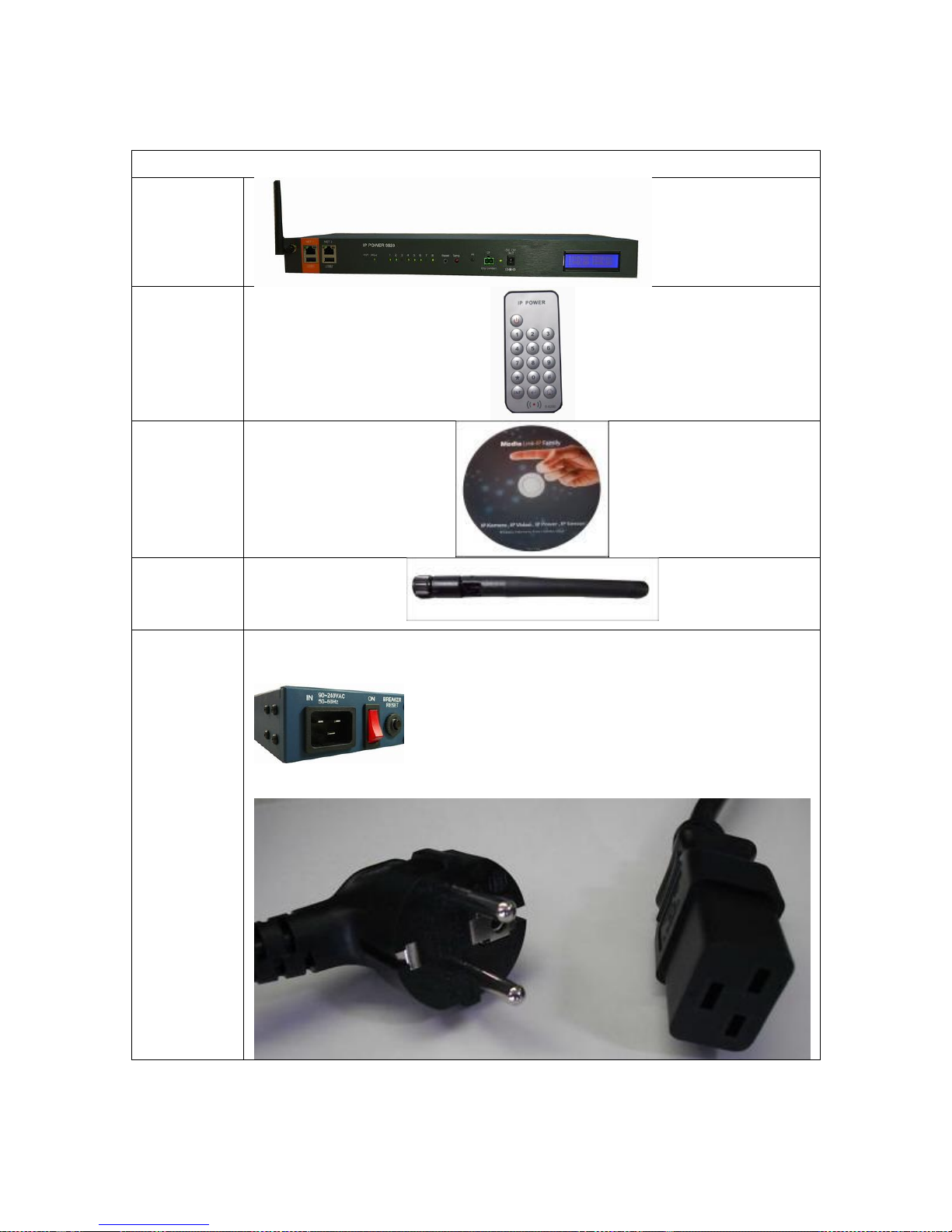
Package Contents
1. 9820
Unit x 1
2. IR
Remote
Power
Control
3. 9820
Installation
CD
4. WiFi
Antenna
X 1 pcs
5. Input
Power
Cable
(option)
The power inlet SPE is C20 . Please double check the power cable compatible
for 10/15/20 amp current loading ( depends on user device power consumed ) .
Power cable outlook example : Europe Style
- 8 -
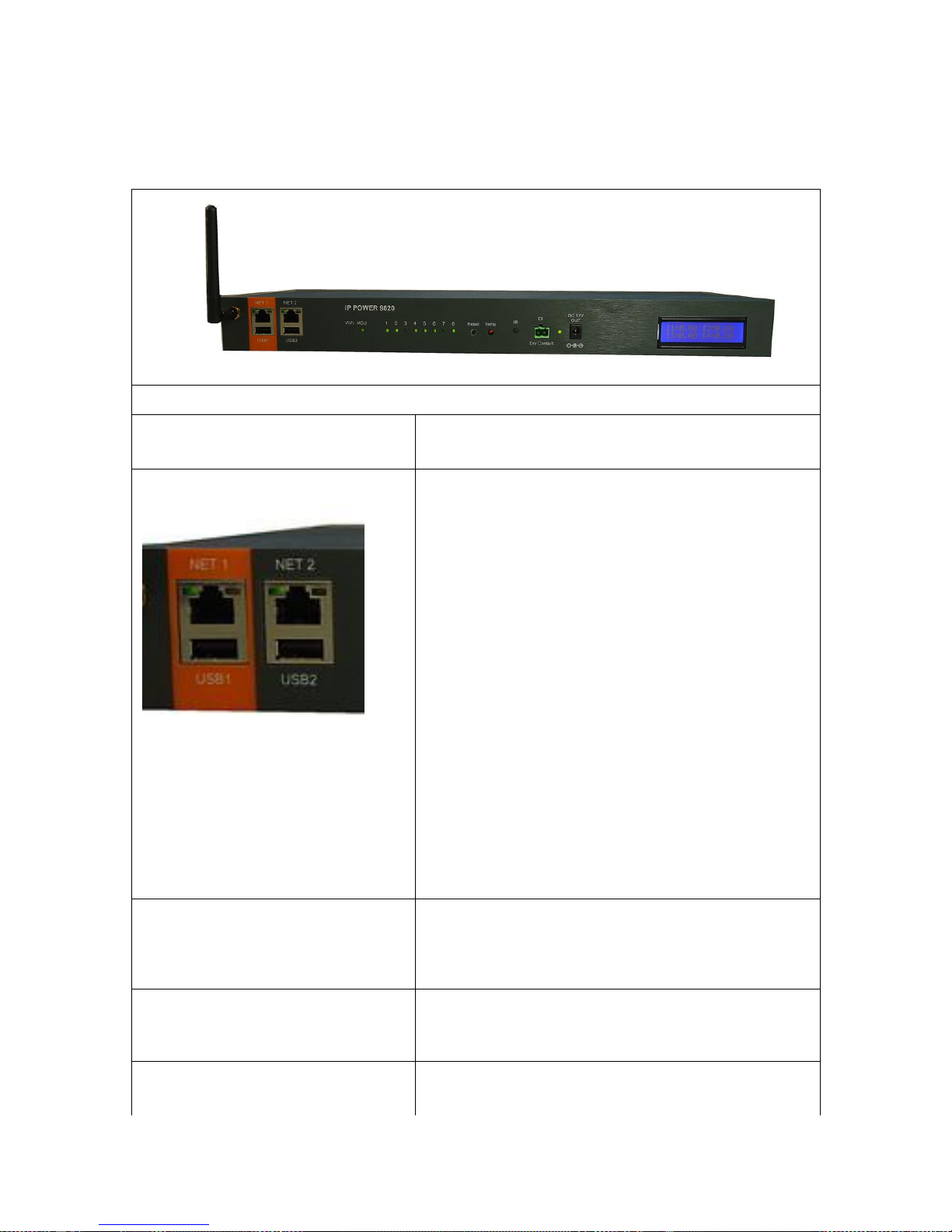
Interface Description
From Left side to right side
Wifi Connection :
Connect with the WiFi Antenna in package .
Network & USB :
Network Connection :
For 10/100 Mbps network .
There are 2 network RJ45 connect :
NET1 - Orange is for network connection
NET2 – Gray is for by pass as hub function only
Please connect NET1 to the Router/ Hub / IP Switch.
USB Connection :
For USB Camera / USB Flash Drive .
There are 2 USB 2.0 connectors :
One is for USB Camera connection for USB Web
Camera with UPNP & video format as M-JPG / YUV.
Another one is for USB Flash Drive saving current
& temperature sensor data as CSV files
Please do not connect more than 1pc. USB Camera to
9820.
WiFi - Signal light
WiFi Signal light in flash Green . The Indicator shows
the WiFi signal transfer status. The light will be keep
flash as WiFi connected .
MCU - light
For internal developing purpose. Green light is always
ON
Number 1 to 8 - Outlet status
To indictor the power ON /OFF status of each outlet
Light in Green : power ON
Front View
- 9 -

Light in RED : power OFF
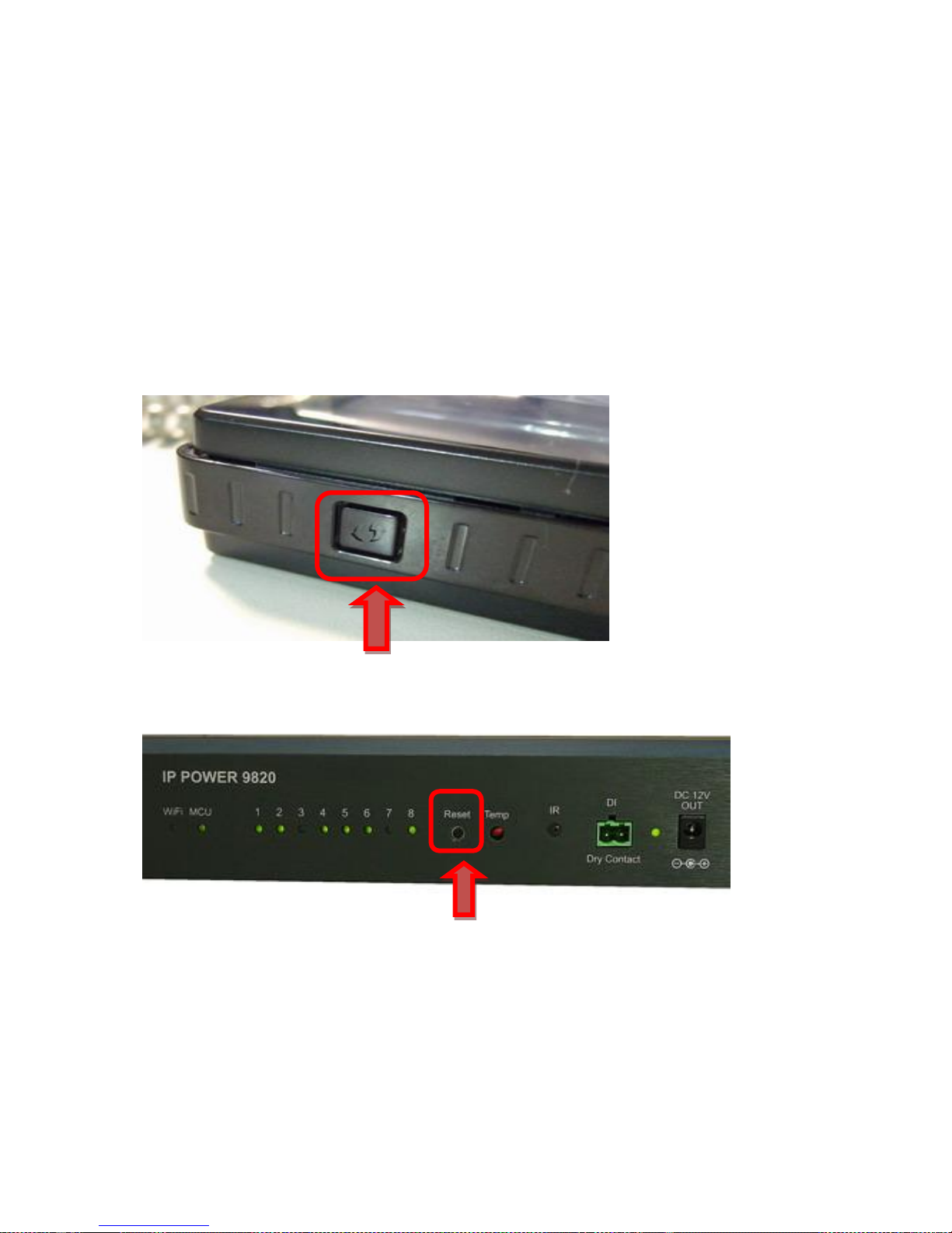
Reset :
To There are two functions for this button.
* Enable WPS function by one short click
refer page #16 for details.
* Set back to default setting by long press
To reset to original manufacture settings, hold down the
reset button with a sharpen pin for
5- 6 seconds then release. There are THREE beeps
response ( short –- mid long – short ) which means
reset successfully and 9820 will be rebooted itself ( one
beep after reboot ) and most information go back to
default setting .
Temp :
This is Temperature Sensor ( RED) to detect the
temperature around of 9820 .
The detect range is 0 ~ 60℃ / 32 ~ 140℉ .
IR :
This area is for receiving the signal from handheld IR
remote controller which comes in shipping package.
DI :
Dry Contact
Power Light :
Device power .
DC 12V Out
Supply DC 12V 1A power.
LCD Display :
Show the IP address , Temperature, Voltage and
current of each port .
- 10 -
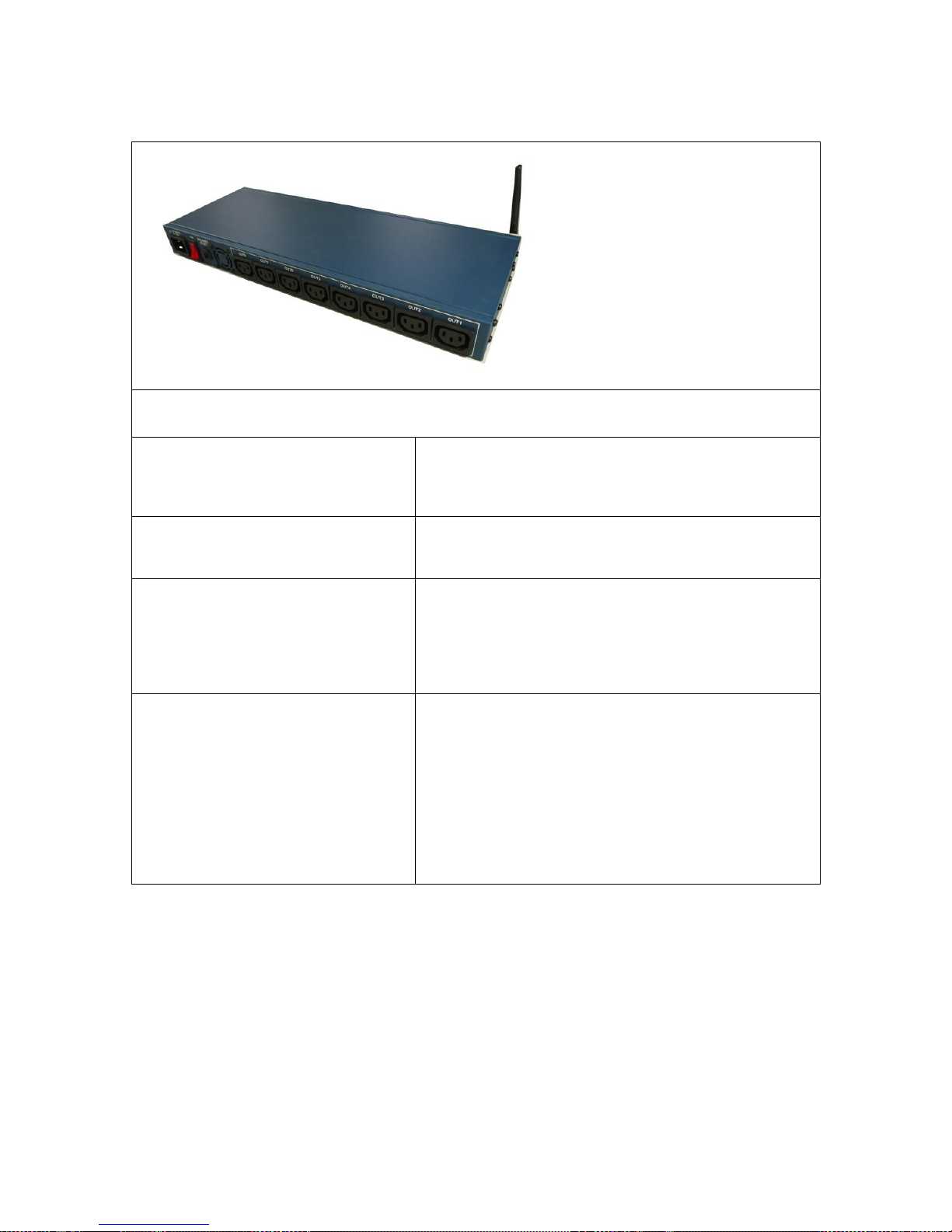
Rear View
From Left side to Right side
Power Inlet :
90~240 VAC & 50~60HZ
IEC320 C20. 20A / 250V AC
1 Power Switch:
The Power switch turns on the input power.
Breaker Reset :
This is Fuse protection to prevent electrical surges
from damaging the unit. The 9820 comes with one
spare fuse in the unit.
8 Outputs:
There are 2 different outlets by different model :
9820-S : IEC 320 C13 .
The Maximum current of each outlet is 8Amp .
9820-T : NEMA 5-15R
The Maximum current of each outlet is 8Amp .
- 11 -

Setting up user device
Before we Start
*Before setting up the device make sure of the following:
1.) All the package contents are all included if anything is missing please contact the dealer
where the device was purchased from.
2.) Check the power input cable is working correctly.
3.) Check all cables to make sure there are no problems with it.
Hardware Connection
Please refer following procedure :
1.) Connect the Ethernet cable (RJ45) to the 9820 to user local area network.
2.) Then connect the power cable into the power input port of the 9820.
3.) Connect the device that user would like to control to the output plug on the top of the 9820.
4.) Switching the power source to ON status , this switch is located at the rear of 9820.
5.) After power on for around 45 seconds , there is a short beep sound for 9820 which means
the system reboot successfully
6. ) Go to page #16 for software installation guide – use IP Edit to log in the webpage of 9820.
Note: To change the network setting for WiFi connection ( if user Router without WPS function ) ,
please go to page # 19 to setup the WiFi connection manually .
Software Installation
The Media Link - IP Family CD comes with the device , it will have all the necessary software to
run and setup the device.
IP Power Software:
IP Edit (Required)
IP Power Center *( For multiple IP Power devices control )
- 12 -

Installing Software
1.) Place the Media Link-IP Family CD into the CD/DVD Rom drive.
(The CD should auto run but if it does not go to the CD/DVD Rom drive and select the
“autorun.html” file.)
2.) Click on the IP Power Section Bar
3.) Select the IP Power 9820
4.) All the available downloads for the 9820 will be shown
5.) Download the required software – IPEdit.exe - by clicking on the download button.
Then user can select to connect 9820 by LAN or by WAN / WAN- WPS
- 13 -
Connection by WiFi- WPS ( WiFi Protection Service )
IP Power 9820 support WPS function which can assist user setup the WiFi connection of user`s
router and IP Power 9820 automatically . Before using WPS function, please check user WiFi
router and see if there has WPS function first . There should have a button name “WPS / QCC
“ or a sign on the router for user to click easily.
Please refer following steps to setup WiFi –WPS connection
Step 1: Power on the 9820 - only connect power in but do not connect the LAN cable , user
will hear one short beep in 40 seconds means 9820 boot successfully
Step 2: Press the “WPS button” of user WiFi Router. ( Please check the WPS function on own
router ) .
Step 3 : Just one short press the “ Reset button” of 9820 and then there is one long beep
which means the WPS function of 9820 enable .
Step 4: After few seconds , there are 2 short beep Which means WPS connection
successfully ( If WPS connection fail , there is one long beep mean the connection fail.
Please go back to step 2 and try again )
WPS Quick procedure :
One short press “ reset “ button on 9820 One Short beep 5-10 seconds short 2
beeps WPS connection successful
- 14 -

Step 5: There is one short beep in 45 seconds which means 9820 boot up successfully .
Step 6 : Execute IPEDIT.exe . The device name with (w) mean the WiFi IP address of this
device . There is WiFi IP address of 9820 shown in IPEDIT.exe as following :
If can not see the IP in the area of Local Devices of IPEDIT.exe. Please disable the
Firewall and Anti Virus software temporally .
Step 7 : Double click the IP address and user PC will execute web browser like IE ,Firefox or
Google Chrome and there is wizard pop up to enquire the Username and Password .
Username : admin Password : 12345678
Step 8 : For the WiFi connection by WPS way , user can check here :
Network WiFi Info Profile list
To make this WiFi IP Address can be found on Internet, please arrange 2 settings as log in the
9820 webpage:
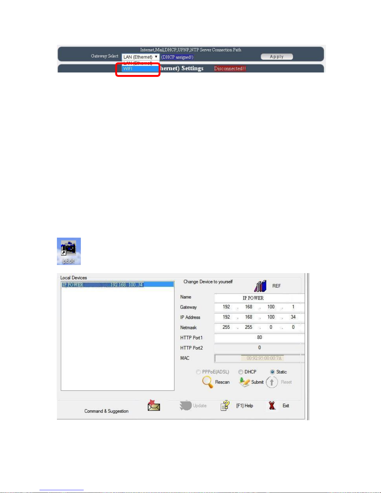
1st : Please go to “ Network Setting Default gateway Setting “ and change as WiFi for the
Default gateway Setting .
- 15 -
2nd : Please do the port mapping / port forwarding in your router ( Need to check the router
manual ).
Connection first by LAN –Network cable then setup for WiFi connection
Without WPS , user can use LAN network cable to connect 9820 first .
Please refer following steps to setup LAN connection
Step 1: Connect the LAN cable to 9820 .The LAN cable should be connected to a Router / HUB
+ Router.
Step: 2 : Connect power cable to 9820 and Power on the 9820 .There is one short beep in 45
seconds after 9820 power up .The short beep means 9820 boot up successfully
Step 3 : After hear the one short beep , please execute IPEDIT.exe . There is IP address of
9820 showed in the right side of IPEDIT.exe following :
If can not see the IP in the area of Local Devices of IPEDIT.exe. Please disable the
Firewall and Anti Virus software temporally .
- 16 -
Step 4 : Double click the IP address and user PC will execute web browser like IE ,Firefox or
Google Chrome and there is wizard pop up which inquire username and password .
Username : admin
Password : 12345678
LAN connect by IP Search software “ IPEDIT “
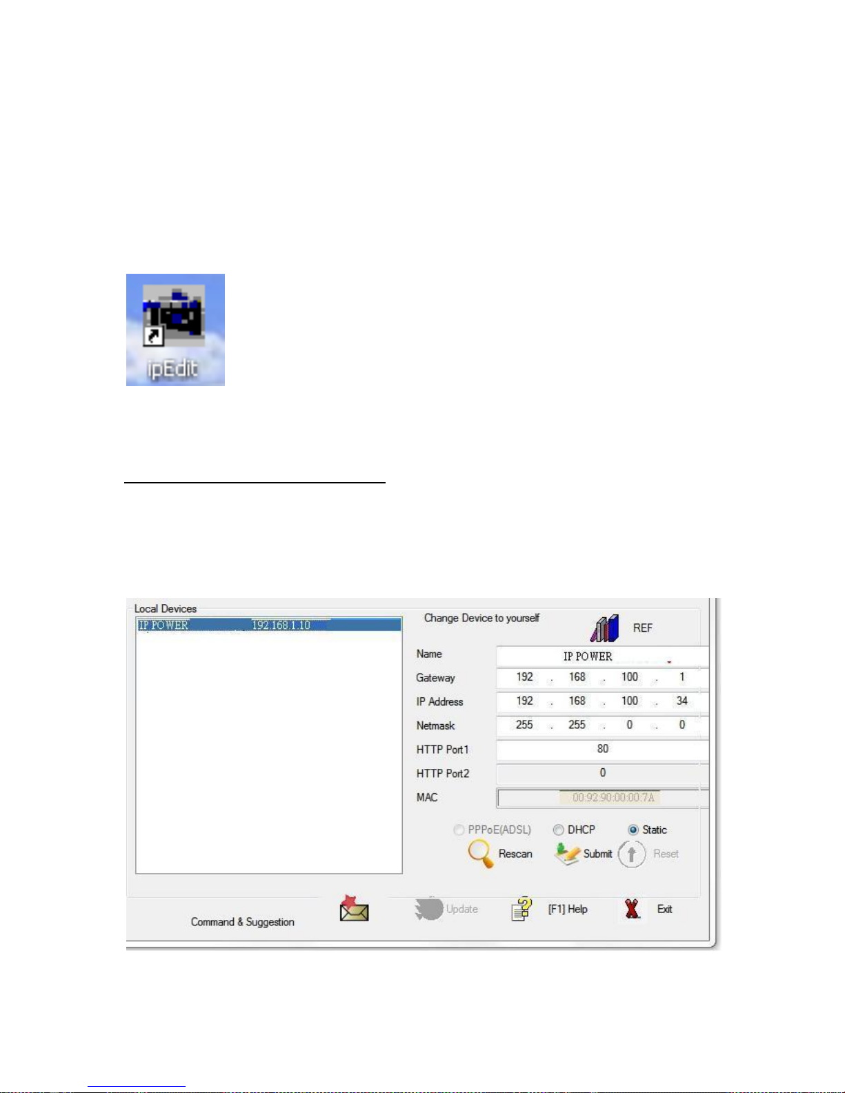
IP Edit is a search tool designed to search, configure, or access the IP Power 9820 from a local
networked computer.
IP Power 9820 Default Login / Password
Default IP: 192.168.1.168 (When no DHCP is apparently)
Default Login: admin
Default Password: 12345678
1.) In the local devices section user will see user device show up if connected correctly.
- 17 -

If can not see the IP in the area of Local Devices of IPEDIT.exe. Please disable the
Firewall and Anti Virus software temporally .
2.) Select the 9820 device and the device information will pop up on the right.
3.) Check to see that the gateway IP and the IP Address (9820) match user current network.
If not, type in the correct information, then hit the submit button to save changes.
For example:
If user have the following information regarding the 9820 and user network
User PC Network :
Computer IP Address: 192.168.1.122
Gateway: 192.168.1.1
Sub Net mask: 255.255.255.0
Port: 80
User 9820 in IPEDIT :
9820 IP Address: 192.168.100.34
Gateway: 192.168.100.1
Sub Net mask: 255.255.0.0
Port: 80
Since the IP Address of the 9820 is : 192.168.100.34
User will need to make sure that the first 3 segments of user 9820 IP Address
must match the first 3 segments of user gateway IP.
First 3 Segment of Gateway Address: 192.168.1.X
So user new IP Address for the 9820 should be: 192.168.1.XXX
New Network Information
9820 IP Address: 192.168.1.26
Gateway Address: 192.168.1.1
Local Computer IP Address: 192.168.1.122
Sub Net mask: 255.255.255.0
Port: 80
4.) Press the rescan button to see if changes have been made.
5.) Double click on the device in the local device section and an IE web browser
with the device login will pop up.
6.) Type in the default Login and IP Address to enter the device.
Default Login : admin
Default : 12345678
Notice :
- 18 -
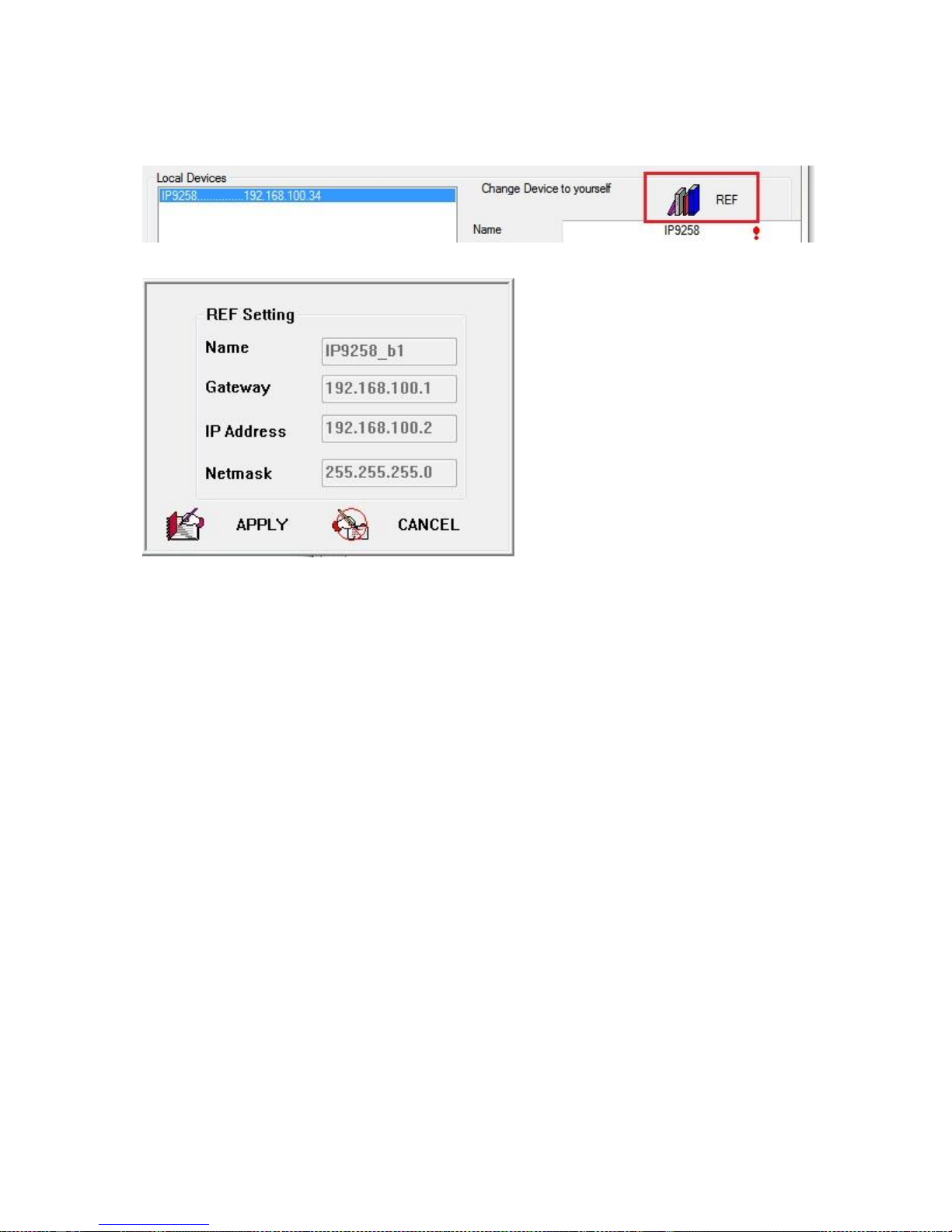
* User can click " REF " in IEPDIT to auto search proper IP setting for 9820.
It will take few minutes to show the suggest wizard.
Please click APPLY as seeing the suggest wizard , click " yes " to ignore the remind
message of IP being used and then type the username and password to change the IP setting.
Username : admin
Password : 12345678
Notice :
# Segment : The first 9 digits of the IP Address .
EX: The IP of user PC is 192.168.100.122. If the “ Local IP Address “ at WiFi Info is 192.168.100.
x ( X can the value of 1~252 ) , user PC can get into the webpage of 9820 .
# Please press “Rescan “ to search the router near by again if can not see user router in the list.
- 19 -
WiFi Connection after log in webpage by LAN :
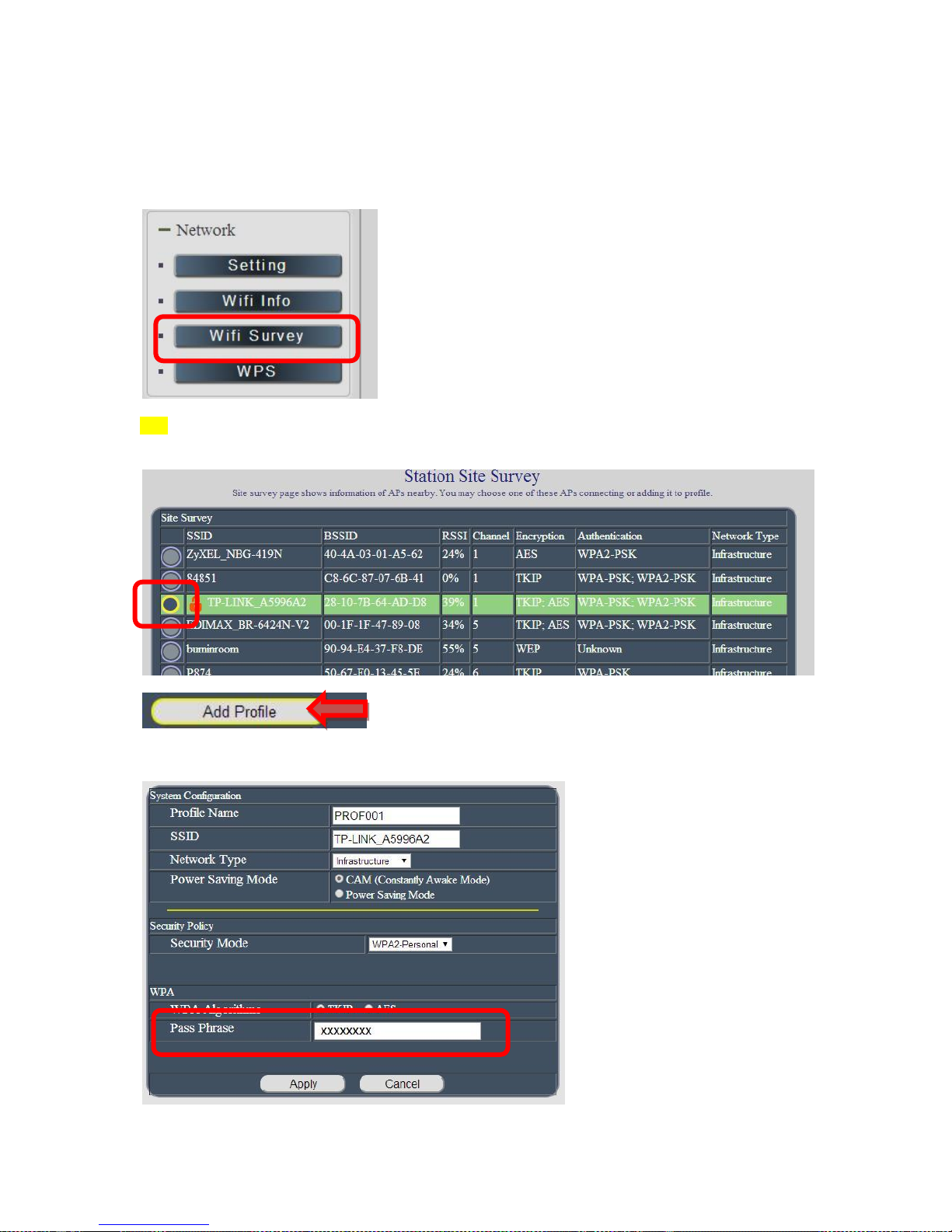
After log in 9820 , to connect by WiFi , please go to Network WiFi Survey to add the WiFi
router in to 9820 WiFi profile .
1) As go to WiFi Survey page, there is a list for the available WiFi router near 9820 . Please
select the one plan to use and click “ Add Profile “
9820 will auto get the most information of user router and user just need to type the password
to connect with the WiFi router then click “ Apply “
- 20 -
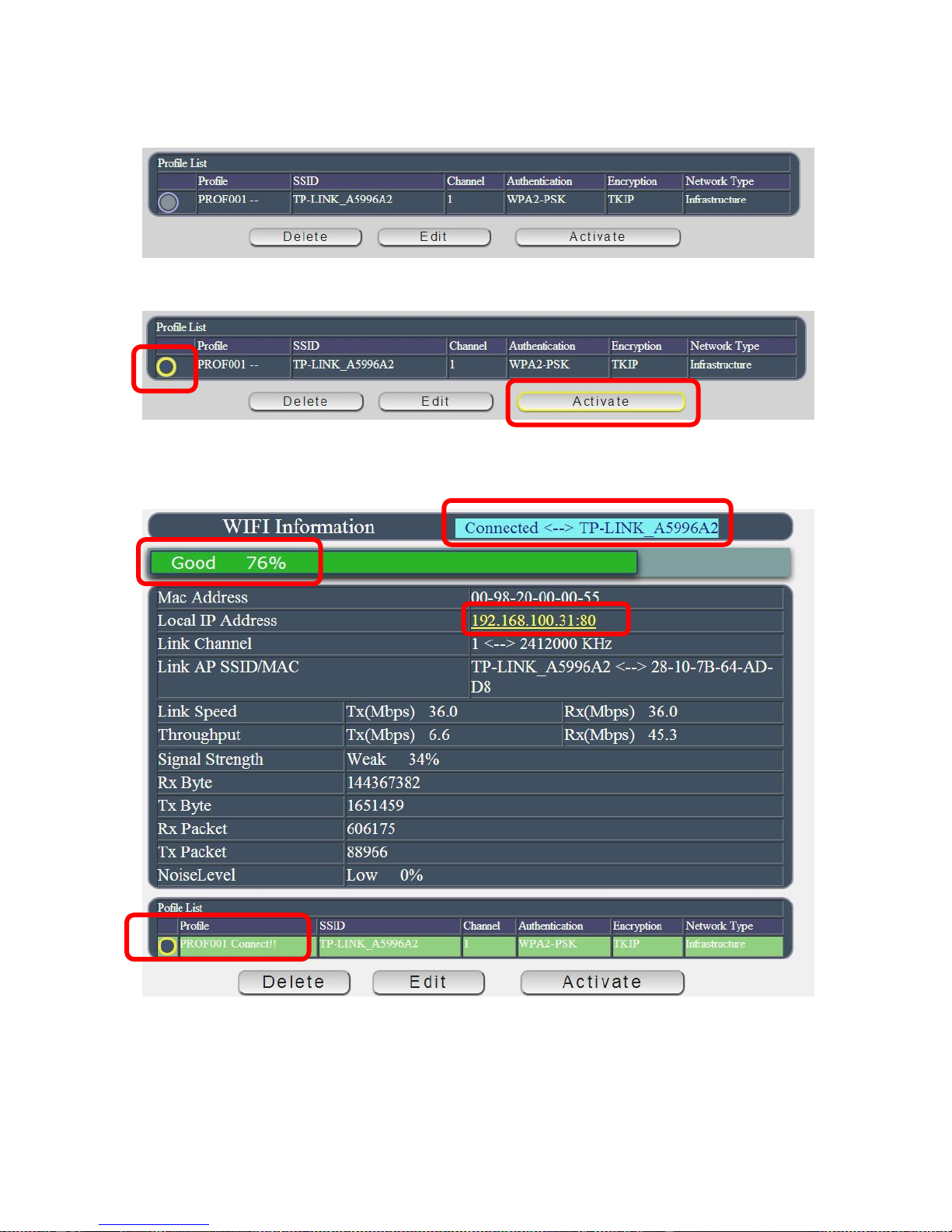
Then user can get the router information in “ Profile list “ section as following pictures
Select the router and press “Activate “
As connection successful , the page will turn to “WiFi Information “ and show the information .
Now user can see the new WiFi IP address which can be found by software IPEDIT.
Then user can remove the LAN cable and re-log in the 9820 by IPEDIT re-search of above WiFi
IP address.
- 21 -
Internet Setup
There are two ways to control the IP Power 9820 over Internet :
If need full control through webpage on Internet , please setup Port Mapping / Port
Forwarding in user router. Please check user Router owner’s manual .
If just want to control each port ON or OFF in IP Power 9820, user can install our own
software “ IP Power Center “ and enable IP Server function as following . Please refer to the
“IP Power Center “ manual in attached CD .
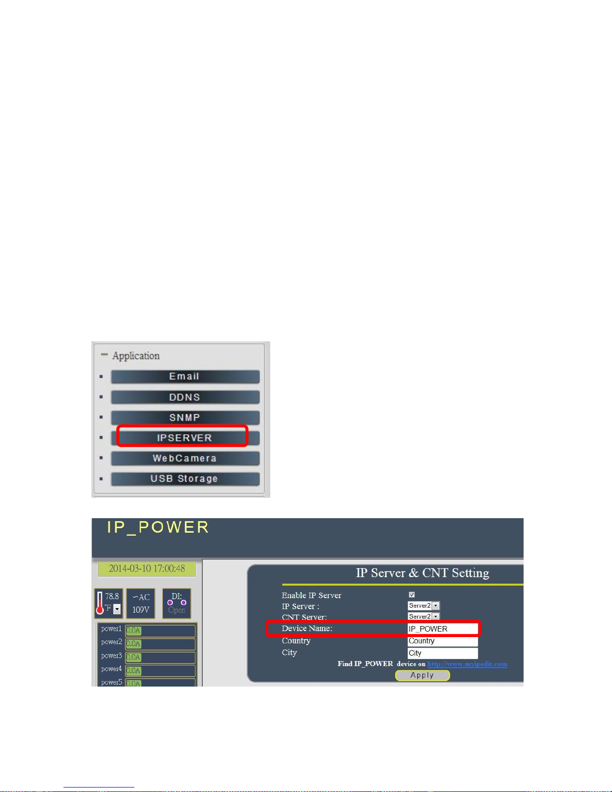
Using IP Server
IP Server is a function which allows user to search for the device easily without having to
remember long complicated IP address. Instead, if user know the device’s name of user IP
Power device and user can easily find IP Address with IP Service. To log in the webpage of
9820 on Internet , user still need to do the “Port forwarding “ in own router.
Before using “IP Server “ , please change the device name of user 9820 to avoid similar
name in host server.
1.) Open IP Edit and select the server that user 9820 is designated to.
- 22 -
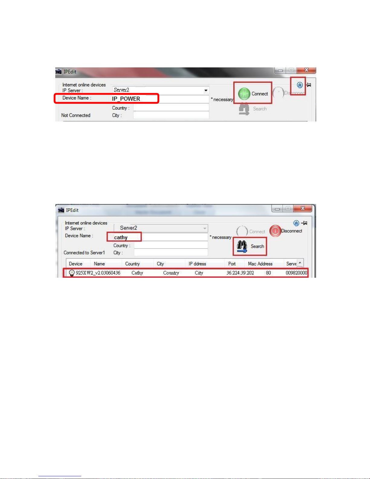
2.) Hit the Green Connect button on the top of IP Edit.
3.) Then type in the 9820 Name that user have selected for the device and press the Search
button.
4.) Find user device and double click on the screen and a IE window will pop up connecting to
user device. *User device must be Port Forwarded for the login screen to appear.
EX: The 9820 device name as Cathy , and user can search the device easily after log in the
webpage and change the default name from “ IP_POWER ” to Cathy
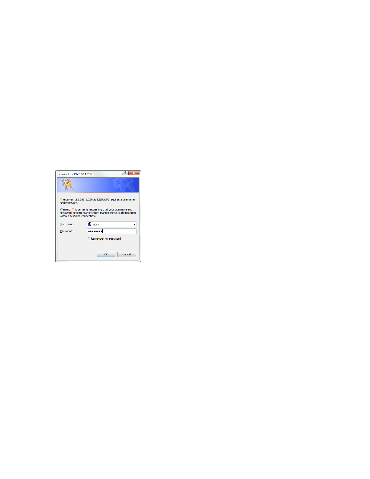
5.) After user have connected to user device, type in the Login and Password for user device
- 23 -
Web Interface
Connect to user Device
Once the 9820 has been setup correctly, log into the device.
First Option
1.) Go to IP Edit find the device that is being used
2.) Double click on the device linked and an IE window will appear with the loading screen
Second Option
1.) Open Internet Explorer type in the IP Address of the device followed by the : sign.
For example: http:192.168.122.188:9258
192.168.122.188 – IP Address
2.) Once user have typed in the IP address of the 9820 and it is ready to use.
The default username and password for the 9820
Username : admin
Password: 12345678
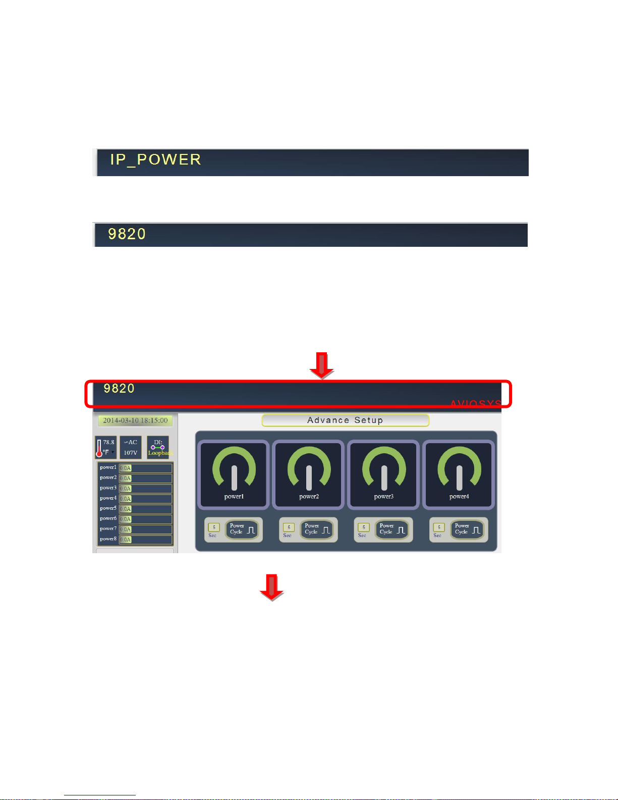
The Control Console
The left Menu of the Web Interface control the functionality and setup of the IP Power 9820.
- 24 -
The IP Power 9820 Console consists of seven main sections which will be explained in details
below.
Device name & to Hide or Display the setting column at left ( for smart phone control )
Information : Time , Temperature , Voltage , DI status , Outlet name & Current Amp value .
IO Control : Controls , Schedule, Ping, Time Line & History
Network : Setting , WiFi Info , WiFi Survey & WPS
Application : Email , DDNS, SNMP, IP Server & Web Camera
System : Management, Sys Information, Sys Log & Firmware
Logout
Connection Period
- 25 -
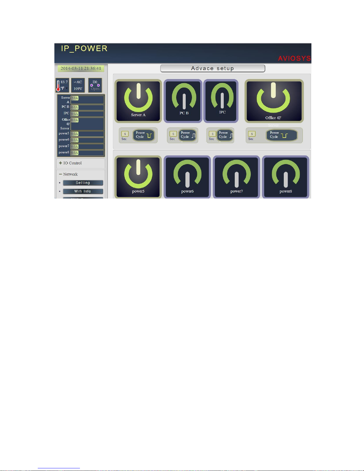
Device name
This section show the device name
Device name :
User can change the device name here : Application IP Server Device name
Change name “ IP_POWER “ as “ 9820 “
Please change the name in English only and do not use symbol like !@#$%^&*()_+
Display or Hide the left setting section :
For smart phone user to control 9820 easily , user can select to show or to hide the left control
section by pressing the blue area near device name for smart phone control :
- With left control section :
Without left control section :
- 26 -
 Loading...