

Page 1
Firmware Version: 2.10
Date Released: Apr. 2014
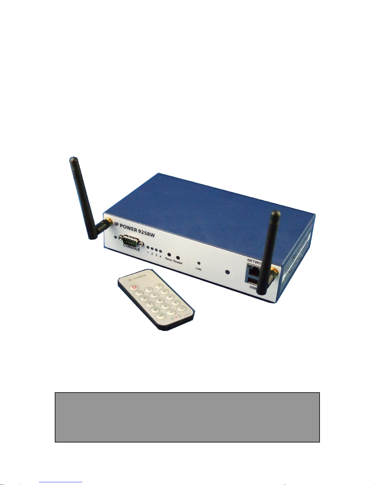
IP Power 9258W2
User Manual
- 1 -
Page 2

Warning: Any changes made to this equipment without permission may cause damages to the device!
IMPORTANT NOTICE
1. IP Power 9258W2 was designed for indoor use, we carry no responsibility for possible
damages caused by outdoor use, especially in the rain.
2. Please use the power adapter provided by the dealer, we carry no responsibility for the
possible damage from using power adapters not provided by us .
4. Do not shake the IP Power 9258W2 in any fashion
5. Please contact the dealer If IP Power 9258W2 is not working properly.
Copyright © 2013 All rights reserved. No part of this publication may be reproduced, stored in a
retrieval system, or transmitted in any form or by any means, electronic, mechanical,
photocopying, recording or otherwise, without the prior written consent of us.
All trademarks and products mentioned in this document are the properties of us.
- 2 -
Page 3

Table of Content
WELCOME ........................................................................................................... 5
Introduction .................................................................................................................................................. 5
PRODUCT OVERVIEW ........................................................................................ 6
Features ......................................................................................................................................................... 6
Specification .................................................................................................................................................. 7
Minimum System Requirements ................................................................................................................. 7
Package Contents ......................................................................................................................................... 8
INTERFACE DESCRIPTION ................................................................................ 9
Front View..................................................................................................................................................... 9
Rear View .....................................................................................................................................................11
Rear View .................................................................................................................................................11
Fuse replacement .........................................................................................................................................12
SETTING UP YOUR DEVICE ............................................................................. 12
Before we Start ............................................................................................................................................12
Hardware Connection .................................................................................................................................13
Software Installation ...................................................................................................................................13
Installing Software ....................................................................................................................................13
Connection by WiFi- WPS ( WiFi Protection Service ) ...........................................................................15
Connection first by LAN –Network cable then setup for WiFi connection ..............................................18
Internet Setup ................................ ................................ ................................................................ ............23
Using IP Server .........................................................................................................................................24
WEB INTERFACE .............................................................................................. 26
Connect to your Device ..............................................................................................................................26
Device name .............................................................................................................................................28
Information : .............................................................................................................................................29
IO Control : ...............................................................................................................................................30
Network : ..................................................................................................................................................48
Application Settings..................................................................................................................................58
System Setting ..........................................................................................................................................71
CONTROLLING THE DEVICE ........................................................................... 76
- 3 -
Page 4

By IR Remote Controller ............................................................................................................................76
CGI HTTP Commands ...............................................................................................................................77
Telnet Control ..............................................................................................................................................79
Serial Com (RS-232) Control......................................................................................................................79
FAQ : .................................................................................................................. 80
- 4 -
Page 5

Welcome
Introduction
IP Power 9258W2 is a new generation of the Power Distribution Unit (PDU) & Remote Power
Control (RPC) system. Its able to connect to the WiFi network plus WPS function for easy &
quick to set up a device to user wireless home/office network and control in the network
With embedded web server and HTTPS protection , 9258W2 supports higher grade security as
working on Internet. User can control power easily and more safely through the web browser on
Windows PC or on Smartphone like Internet Explorer (IE) , Firefox , Google
Chrome , Safari ( iOS ) and Android system.
9258W2 allows user to remote control power up to 4 separate devices on/off via network . As
support SSL & SNMP, user can use public email like Gmail / Hotmail / Yahoo Mail to get the
email as the ON/OFF status change . User can also control by e-mail without doing port
forwarding / port mapping and search the other IP Device in webpage directly .
Besides contorl through web browser , there is Android Apps name “IP Power “ for Android
user to control the outlet power turn ON / OFF, get the meter reading
of Current / Voltage / Temperature and quick search device in LAN / WAN Android phone /
touch panel . User can also use the IR remote controller which comes with 9258W2 to
control outlet on & off directly by the handheld remote controller without need PC operation ,
specially benefit in no networking . no PC system environment or emergency use for quick
response in second.
Not only control manually, 9258W2 supports Auto Ping , Time Scheduler which is more
suitable for factory / office / home automation .
Besides power control , through 9258W2 , user can also check the power usage WH ( watt per
hour ) , current consumption of each port , and Temperature value , LOG information &
send LOG to assign IP(Syslog) , get consumed history & LIVE Line Chart in webpage.
IP Power 9258W2 also can connect USB Camera to view the area near 9258W2. For smart
phone customer , 9258W2 has QR code of different network to log in fast and easy. Use can
directly search the other IP Device in webpage directly .
For system integrator, there are several popular developing tolls like TelNet , SNMP and HTTP
Command ( SDK) for 2nd development . The various applications of the 9258W2 includes:
Power Management, Server Management, Internet Controllable Timer,
System Integration, Remote Power Control in Remote locations ………….. etc.
User Friendly . Convenience & Powerful ,
- 5 -
Page 6

Product Overview
Features
1. 4 ports Remote power controller for power On, Off and Reboot.
2. Web Server built-in design, directly control by web browser – PC & Smart phone :Internet
Explore (IE) , Firefox , Google Chrome, Safari - iPhone and Android browser of smart
phone. ( Windows , Android & iOS) .
3. Android Apps “IP Power “ – free supply
- Controls the outlet power ON/OFF
- Read the meter of Current / Voltage / Temperature
- Quick search in LAN / WAN ( liek IPEDIT & IP Serice )
4. Support WiFi - Wireless 802.11 N/ B/ G and WPS connection
( WPA-PSK, WPA2-PSK, AES,128-bit WEP,64-bit WEP,TKIP, WPA2,WPA )
5. Support HTTPS , SSL, TCP/ IP , PPPOE, DHCP, DDNS & SMTP
6. Control 4 individual outlet power ON & OFF .
- ax. current per port : 8 Amp
- Max. current total 4 outlets: 10 Amp or
240 Watt for light control like T5 Fluorescent Light
7. Detect the consumed Current & Temperature value & LIVE line chart display
- Current range : 0A ~ 10A
- Temperature : 0 ~ 60℃ / 32 ~ 140℉ . The tolerance of above 3 items are ±5%
8. Live chart display the value of WH ( watt per hour) , Current Amp , Voltage &
Temperature.
9. Support " Inrush Current " for T5 fluorescent light for light control
10. Power Surge protection & FUSE embedded in
11. Support Log function & send to assign IP address (Syslog)
12. Save History as CSV file for application .
13. Support USB for Camera or Flash Drive.
- USB Webcam ( W/ UPNP , M-JPG /YUV) to view the environment.
- USB Flash Drive for saving history / log information.
14. Convenience design for Smartphone :
- Webpage : easy to Control ON/OFF& get meter value
- Android APP “ IP Power”
- 6 -
Page 7

- QR Code : create QR code of the 9258W2 IP address
15. Time Schedule - can pre-set a suitable time to turn power on / off automatically .
16. Support handheld IR Remote controller to control without PC
17. Support Auto Ping for auto control management.
18. Back Up function for quick setup for multiple devices like Time Schedule, Network
Setting
19. E-mail control function & E-mail alarm :
- Receive Email with Current , Voltage & Temperature info. as device boot up.
- Email alarm as over setting at Current and temperature
- POP3 Control : Control each outlet ON/OFF through E-mail .
Support public e-mail -- @gmail.com , @yahoo.com , @hotmail. com ..........etc.
20. Embedded IP Manager to search other IP device in local network in webpage directly.
- Specific software developed by Aviosys and provided free of charge :
- SDK Available : HTTP Command
- IP Power Center - for control multiple Aviosys IP devices in same software
- CNT software ( Cross Network Technology )- allows user eliminate set up work on any
Router without port forwarding , simply Plug & Play .
Specification
Power input : 100V - 240V
Maximum loading of each output: 8 amp
Maximum of Total loading : 8 amp
Fuse protection : 10 amp ( with spare fuse in socket )
Dimensions: 200 x 140 x 50 mm ( L x W x H )
Weight: 990g
Enclosure – Matel case in blue color
Minimum System Requirements
WINDOS PC OS with network capacity.
Browser : IE 9.0 or above , Firefox, Google Chrome , Safari
RJ45 LAN & Internet HUB & Switch
JAVA version 1.60 or above to check USB Webcam under web browser Internet Explorer -IE
Internet ( for remote access) or Ethernet Network ( Internal Network use) with some type of
Internet connection, (i.e. ADSL, Cable, Dial up or any other forms of Internet service)
- 7 -
Page 8
Package Contents
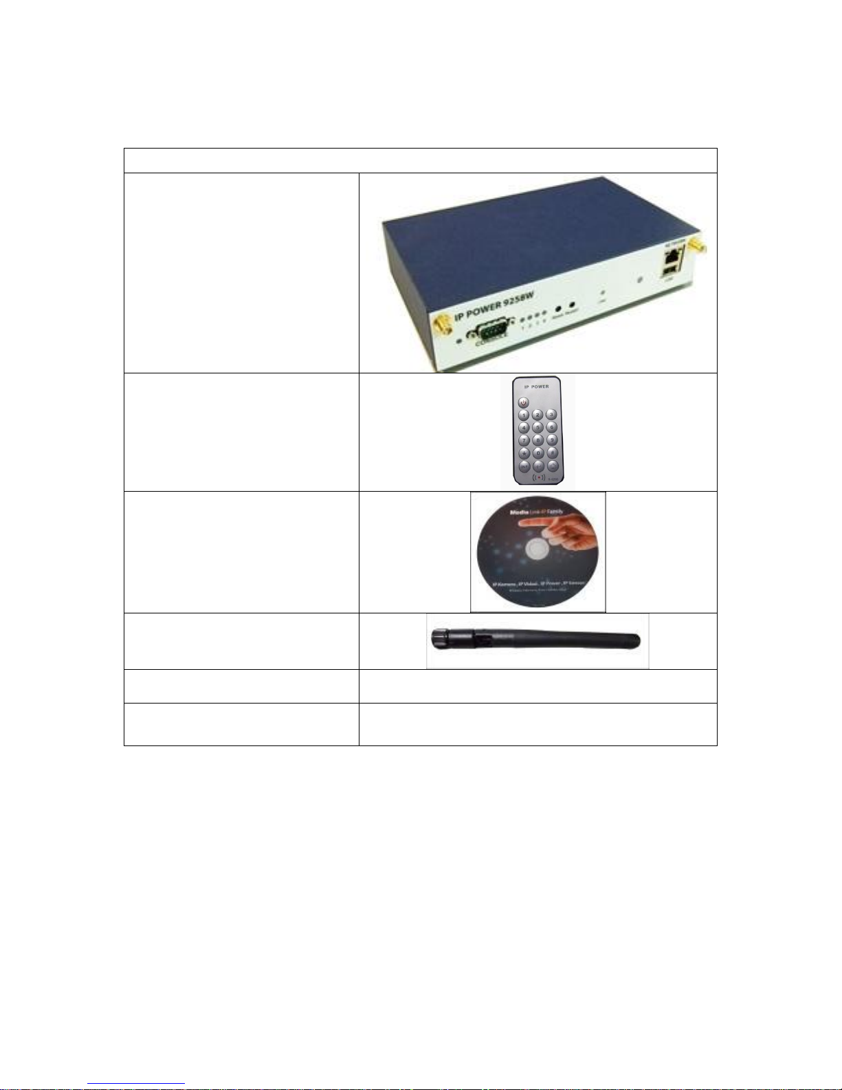
1. 9258W2 Unit x 1
2. IR Remote Power Control
3. 9258W2 Installation CD
4. WiFi Antenna
X 2 pcs
5. RJ45 Cable x 1 (option)
6. Input Power Cable (option)
Please double check the power cable compatible
for 10 amp current loading .
- 8 -
Page 9
Interface Description
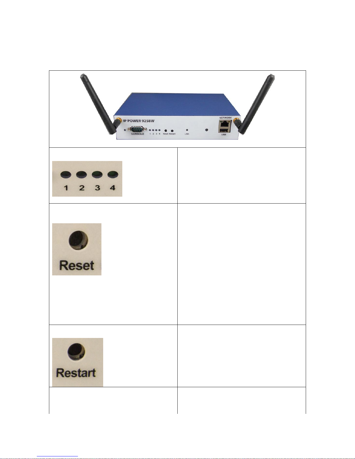
Power Status Indicator:
The Power Status Indicator - Green light ON
as power ON.
Reset :
There are two functions for this button.
* Enable WPS function by one short click
function. Please refer page #16 for details.
* Set back to default setting by long press
To reset to original manufacture settings, hold
down the reset button with a sharpen pin for
5- 6 seconds then release. There are THREE
beeps response ( short –- mid long – short )
which means reset successfully and
9258W2 will be rebooted itself ( one beep after
reboot ) and most information go back to
default setting ( LAN IP )
Restart :
The restart button just resets the device by
turning off and then turning on the power.
Link:
The Link Indicator shows the WiFi signal
transfer status. The light will be ON all the time
and flashing while transfer data.
Front View
- 9 -
Page 10
IR Receiver :
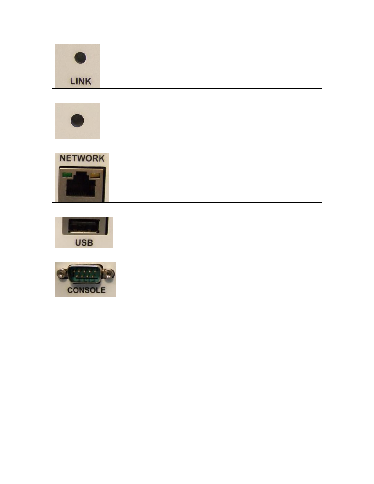
This area is for receiving the signal from
handheld IR remote controller which comes in
shipping package.
Network:
10/100 Mbps network
USB:
USB 2.0 for USB Web Camera. (With UPNP &
video format as M-JPG / YUV )
RS232 Serial Port Console :
Optional – for OEM/ODM only
- 10 -
Page 11
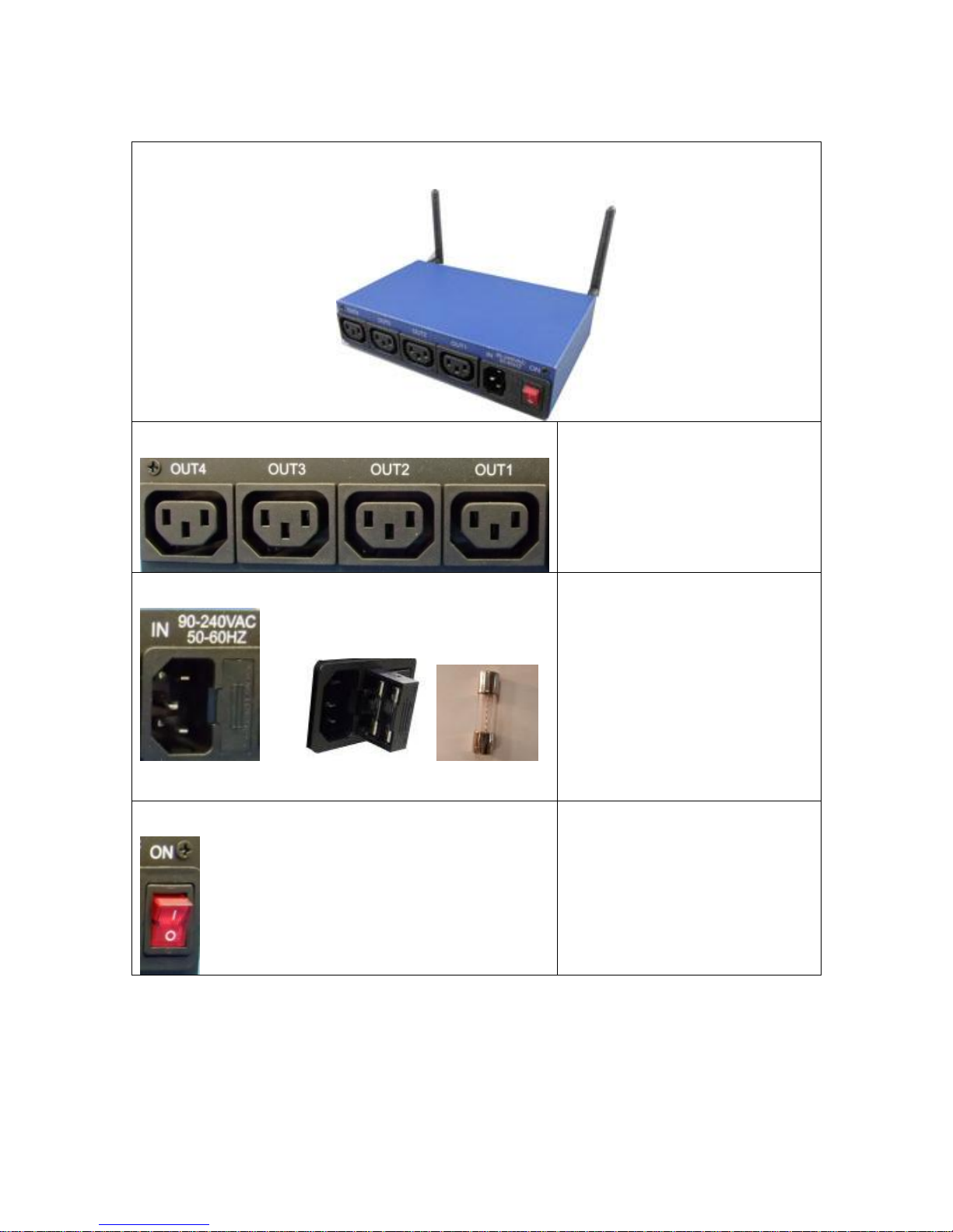
Rear View
Rear View
4 Output Power Ports:
Connect up to 4 separate devices
that will be controlled by the
9258W2. Ports 1 - 4
1 Input Power Port :
In this socket, there is power input
and Fuse socket .
The input power sends power
to the 9258W2.
Fuse : To prevent electrical
surges from damaging the unit.
The 9258W2 comes with one
spare fuse in the unit.
TYPE:U/C GFE 10A 250V (PF)
1 Power Switch:
The Power switch turns on the
input power.
- 11 -
Page 12
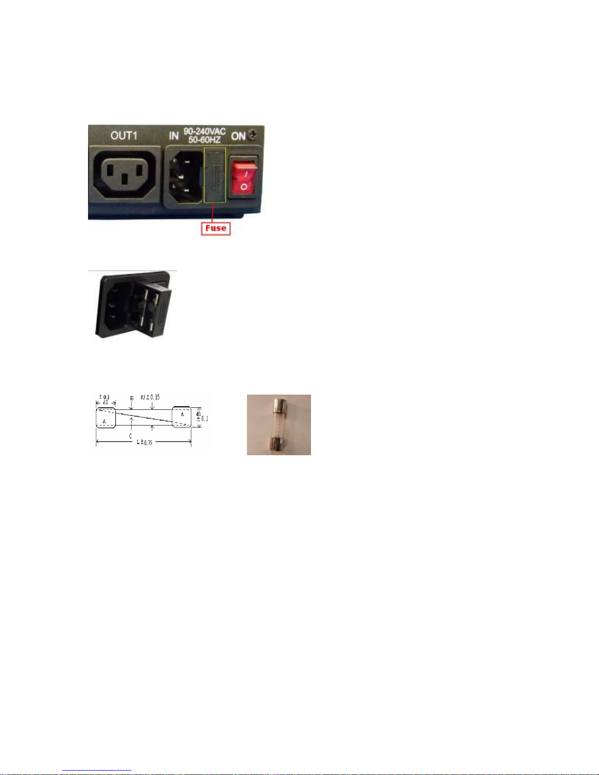
Fuse replacement
1.) The fuse is located between the power switch and the power input plugs.
2.) Carefully remove the fuse holder with a flat screwdriver.
3.) The fuse can be purchased from electronic shops.
Specification : U/C GFE 10A 250V (PF)
Setting up your device
Before we Start
*Before setting up the device make sure of the following:
1.) All the package contents are all included if anything is missing please contact the dealer
where the device was purchased from.
2.) Check the power input cable is working correctly.
3.) Check all cables to make sure there are no problems with it.
- 12 -
Page 13
Hardware Connection
Please refer following procedure :
1.) Connect the Ethernet cable (RJ45) to the 9258W2 to your local area network.
2.) Then connect the power cable into the power input port of the 9258W2.
3.) Connect the device that you would like to control to the output plug on the top of the 9258W2.
4.) Switching the power source to ON status , this switch is located at the rear of 9258.
5.) After power on for around 45 seconds , there is a short beep sound for 9258W2 which
means the system reboot successfully
6. ) Go to page #14 for software installation guide – use IP EDIT to log in the webpage of
9258W2.
Note: To change the network setting for WiFi connection ( if your Router without WPS function ) ,
please go to page # 12 to setup the WiFi connection manually .
Software Installation
The Media Link - IP Family CD comes with the device , it will have all the necessary software to
run and setup the device.
IP Power Software:
IP Edit (Required)
IP Power Center *( For multiple IP Power devices control )
Installing Software
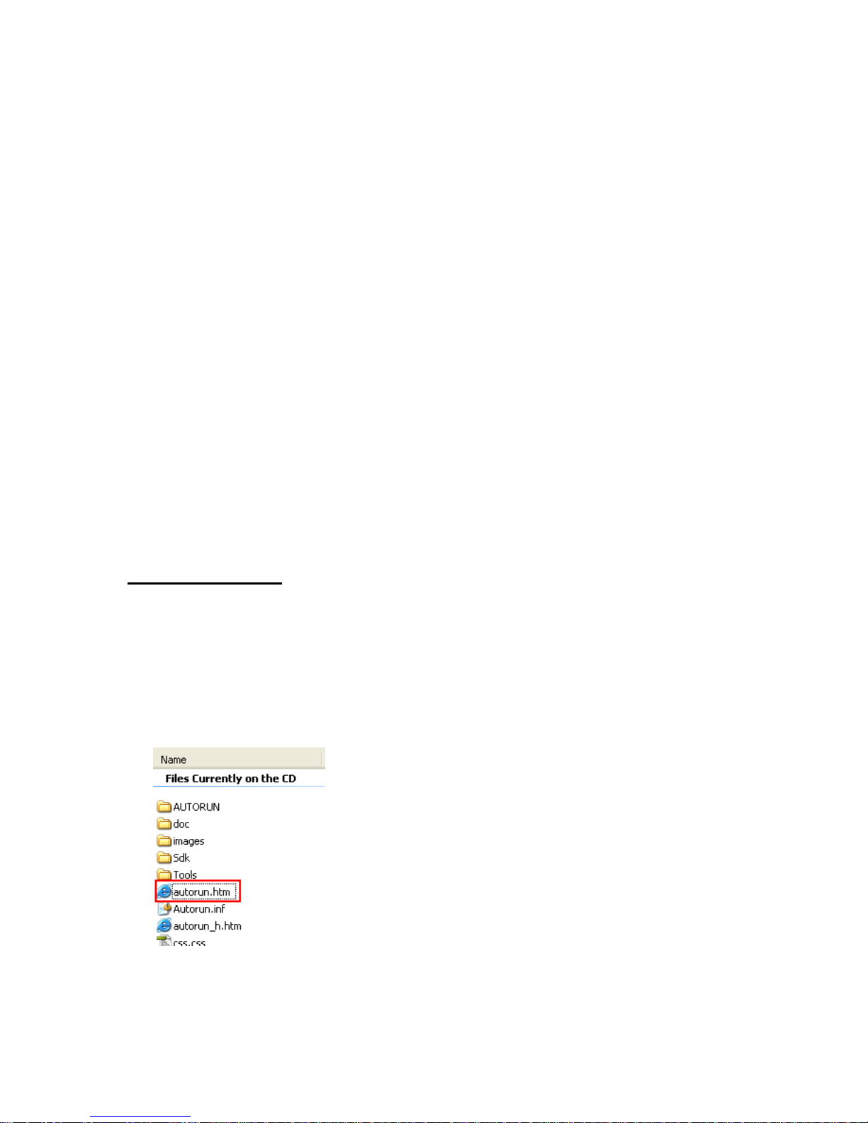
1.) Place the Media Link-IP Family CD into the CD/DVD Rom drive.
(The CD should auto run but if it does not go to the CD/DVD Rom drive and select the
“autorun.html” file.)
2.) Click on the IP Power Section Bar
- 13 -
Page 14
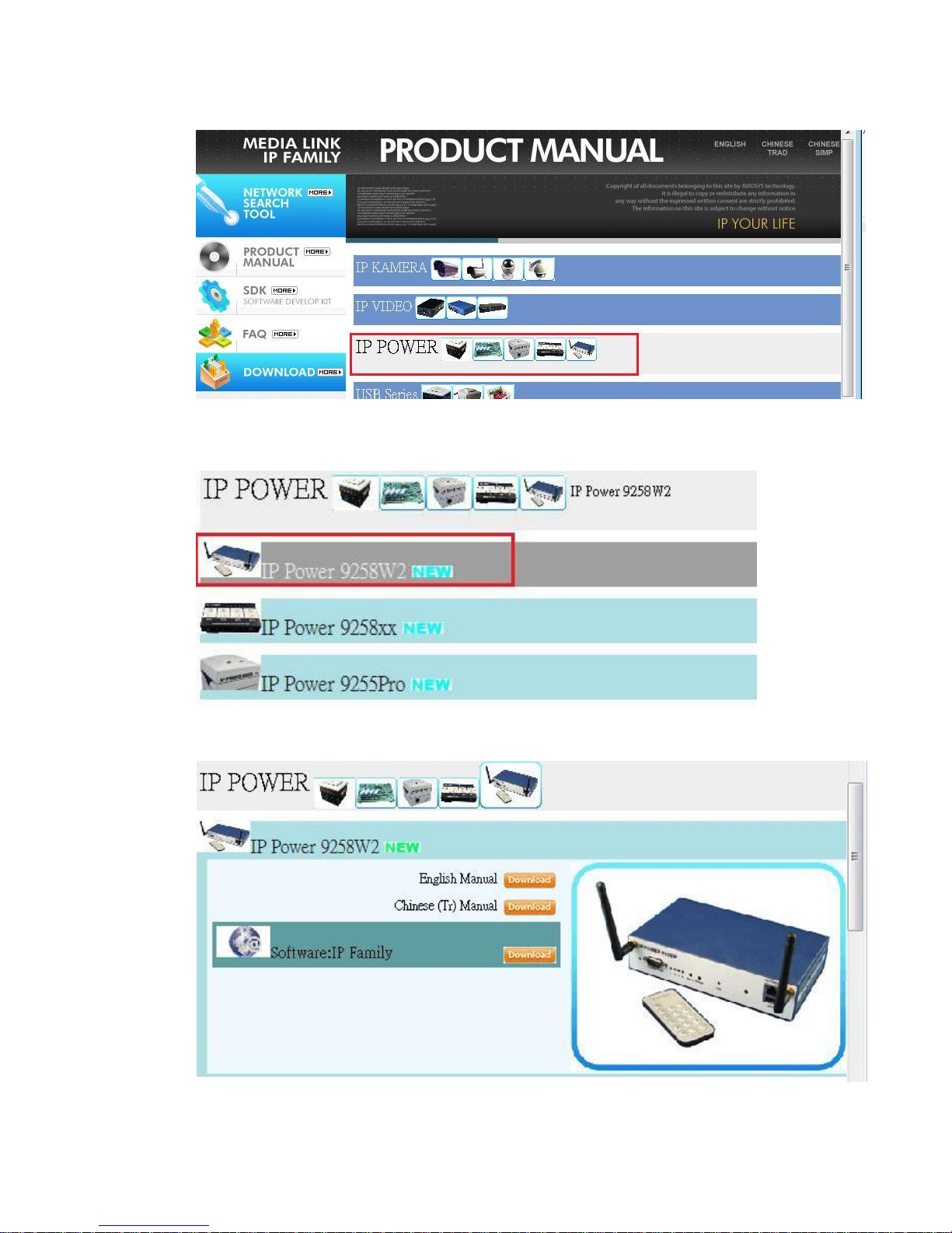
3.) Select the IP Power 9258W2
4.) All the available downloads for the 9258W2 will be shown
- 14 -
Page 15
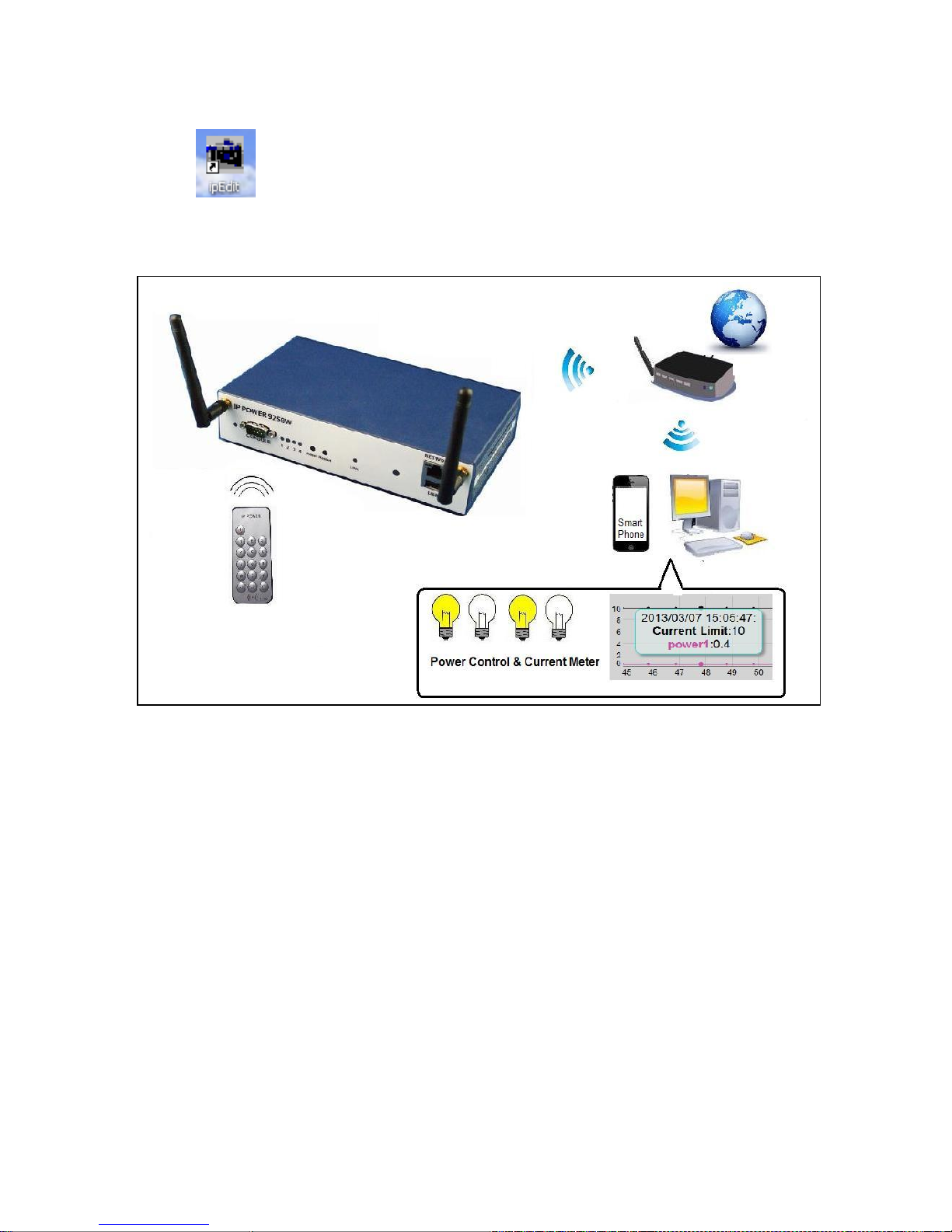
5.) Download the required software – IPEdit.exe - by clicking on the download button.
Then you can select to connect 9258W2 by LAN or by WAN ( WPS)
Connection by WiFi- WPS ( WiFi Protection Service )
IP Power 9258W2 support WPS function which can assist user setup the WiFi connection of
user`s router and IP Power 9258W2 automatically . Before using WPS function, please check
your WiFi router and see if there has WPS function first . There should have a button name
“WPS / QCC “ or a sign on the router for user to click easily.
Please refer following steps to setup WiFi –WPS connection
Step 1: Power on the 9258W2 - only connect power in but do not connect the LAN cable , you
will hear one short beep in 40 seconds means 9258W2 boot successfully
Step 2: Press the “WPS button” of your WiFi Router. ( Please check your router WPS function )
- 15 -
Page 16
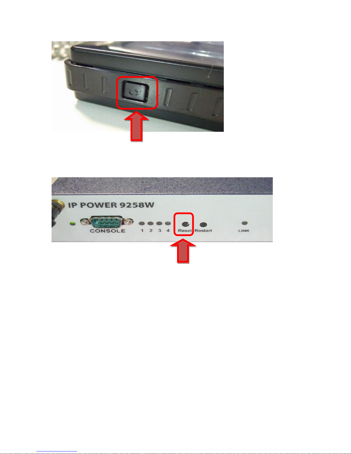
Step 3 : Press One time ( short) the “ Reset button” of 9258W2 and then there is one long beep
which means the WPS function of 9258W2 enable .
Step 4: After few seconds , there are 2 short beep Which means WPS connection
successfully ( If WPS connection fail , there is one long beep mean the connection fail.
Please go back to step 2 and try again )
WPS Quick procedure :
One short press “ reset “ button on 9258W2 One Short beep 5-10 seconds short
2 beeps WPS connection successful
Step 5 : Execute IPEDIT.exe . There is WiFi IP address of 9258W2 shown in IPEDIT.exe as
following :
- 16 -
Page 17
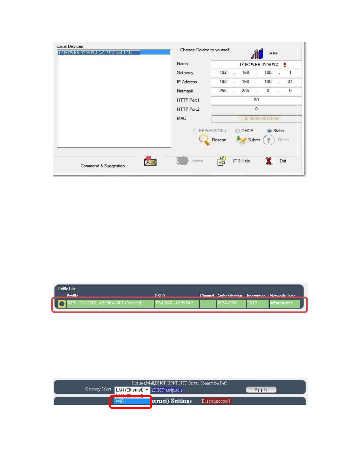
If can not see the IP in the area of Local Devices of IPEDIT.exe. Please disable the
Firewall and Anti Virus software temporally .
Step 7 : Double click the IP address and your PC will execute web browser like IE ,Firefox or
Google Chrome and there is wizard pop up to enquire the Username and Password .
Username : admin Password : 12345678
Step 8 : For the WiFi connection by WPS way , user can check here :
Network WiFi Info Profile list
To make this WiFi IP Address can be found on Internet, please arrange 2 settings as log in the
9258W2 webpage:
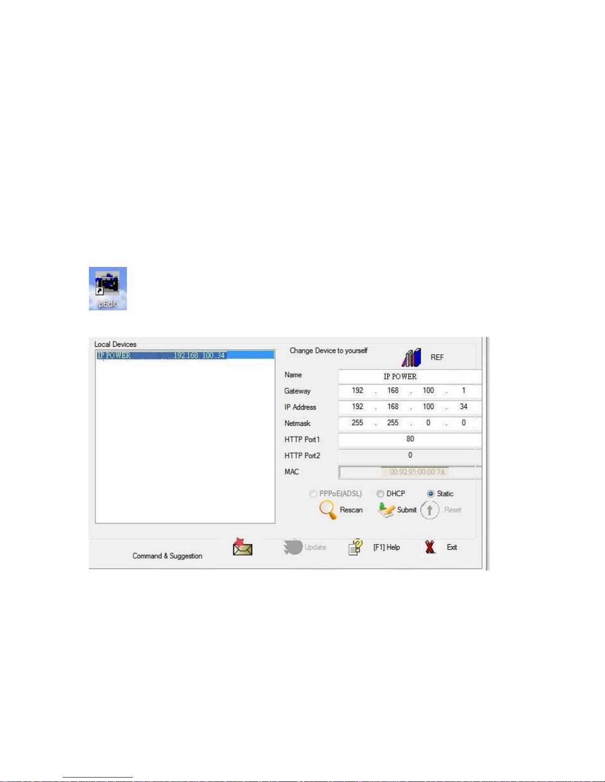
1st : Please go to “ Network Setting Default gateway Setting “ and change as WiFi for the
Default gateway Setting .
2nd : Please do the port mapping / port forwarding in your router ( Need to check the router
manual ).
- 17 -
Page 18
Connection first by LAN –Network cable then setup for WiFi connection
Without WPS , user can use LAN network cable to connect 9258W2 first .
Please refer following steps to setup LAN connection
Step 1: Connect the LAN cable to 9258W2 .The LAN cable should be connected to a Router /
HUB + Router.
Step: 2 : Connect power cable to 9258W2 and Power on the 9258W2 .There is one short beep in
45 seconds after 9258W2 power up .The short beep means 9258W2 boot up successfully
Step 3 : After hear the one short beep , please execute IPEDIT.exe . There is IP address of
9258W2 showed in the right side of IPEDIT.exe following :
If can not see the IP in the area of Local Devices of IPEDIT.exe. Please disable the
Firewall and Anti Virus software temporally .
Step 4 : Double click the IP address and user PC will execute web browser like IE ,Firefox or
Google Chrome and there is wizard pop up which inquire username and password .
Username : admin
Password : 12345678
- 18 -
Page 19
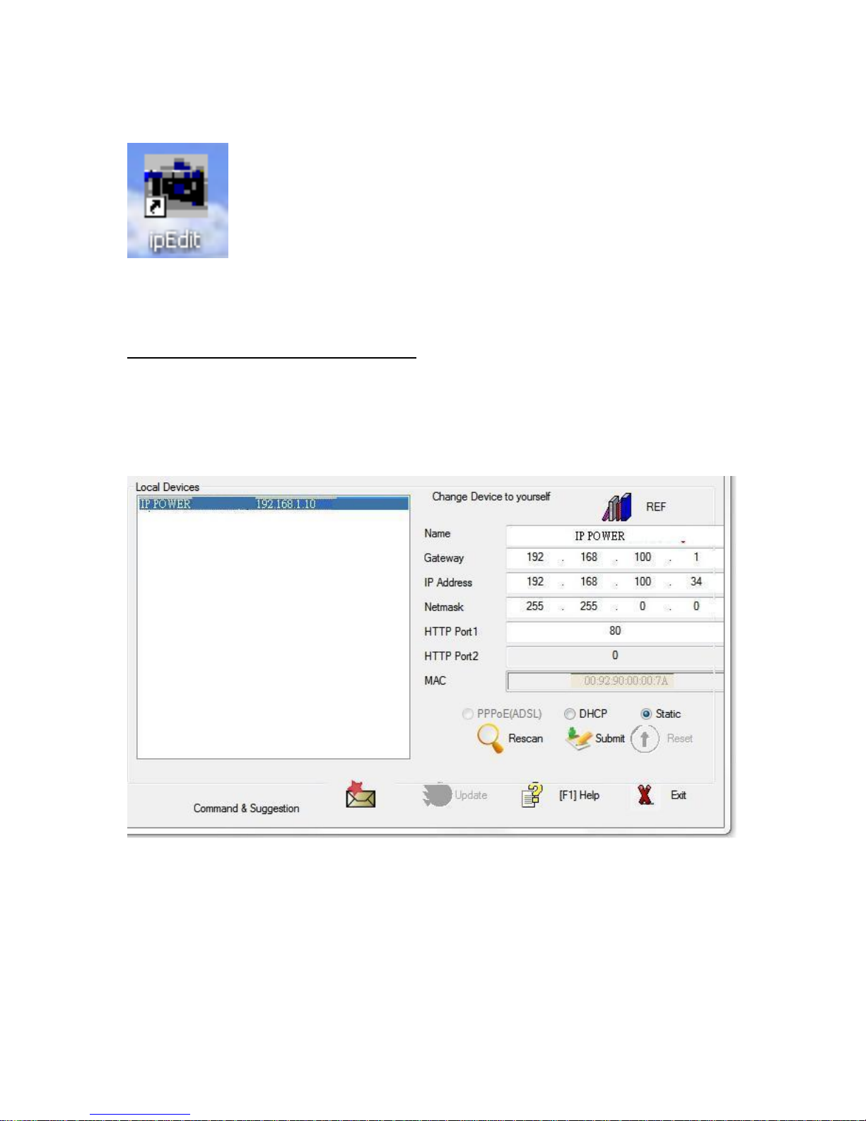
LAN connect by IP Search software “ IPEDIT “
IP Edit is a search tool designed to search, configure, or access the IP Power 9258W2 from a
local networked computer.
IP Power 9258W2 Default Login / Password
Default IP: 192.168.1.168 (When no DHCP is apparently)
Default Login: admin
Default Password: 12345678
1.) In the local devices section user will see user device show up if connected correctly.
If can not see the IP in the area of Local Devices of IPEDIT.exe. Please disable the
Firewall and Anti Virus software temporally .
2.) Select the 9258W2 device and the device information will pop up on the right.
3.) Check to see that the gateway IP and the IP Address (9258W2) match user current network.
If not, type in the correct information, then hit the submit button to save changes.
- 19 -
Page 20
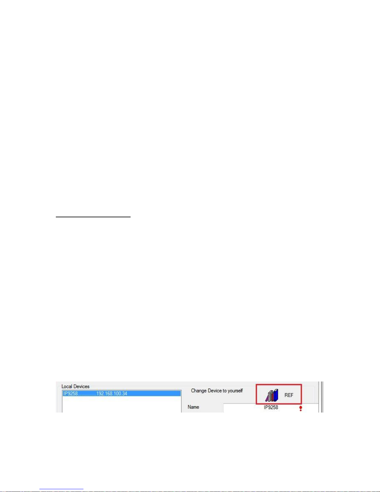
For example:
If user have the following information regarding the 9258W2 and user network
User PC Network :
Computer IP Address: 192.168.1.122
Gateway: 192.168.1.1
Sub Net mask: 255.255.255.0
Port: 80
User 9258W2 in IPEDIT :
9258W2 IP Address: 192.168.100.34
Gateway: 192.168.100.1
Sub Net mask: 255.255.0.0
Port: 80
Since the IP Address of the 9258W2 is : 192.168.100.34
User will need to make sure that the first 3 segments of user 9258W2 IP Address
must match the first 3 segments of user gateway IP.
First 3 Segment of Gateway Address: 192.168.1.X
So user new IP Address for the 9258W2 should be: 192.168.1.XXX
New Network Information
9258W2 IP Address: 192.168.1.26
Gateway Address: 192.168.1.1
Local Computer IP Address: 192.168.1.122
Sub Net mask: 255.255.255.0
Port: 80
4.) Press the rescan button to see if changes have been made.
5.) Double click on the device in the local device section and an IE web browser
with the device login will pop up.
6.) Type in the default Login and IP Address to enter the device.
Default Login : admin
Default : 12345678
Notice :
* User can click " REF " in IEPDIT to auto search proper IP setting for 9258W2.
It will take few minutes to show the suggest wizard.
- 20 -
Page 21
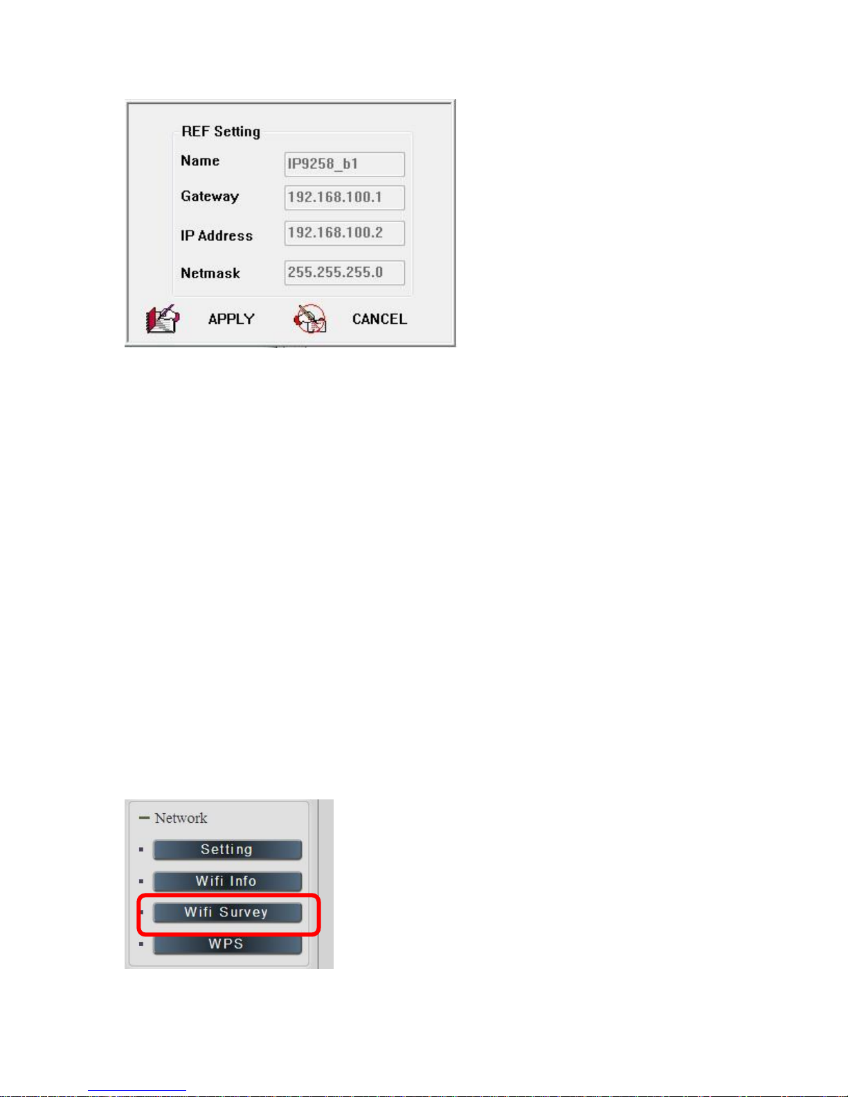
Please click APPLY as seeing the suggest wizard , click " yes " to ignore the remind
message of IP being used and then type the username and password to change the IP setting.
Username : admin
Password : 12345678
Notice :
# Segment : The first 9 digits of the IP Address .
EX: The IP of user PC is 192.168.100.122. If the “ Local IP Address “ at WiFi Info is 192.168.100.
x ( X can the value of 1~252 ) , user PC can get into the webpage of 9258W2 .
# Please press “Rescan “ to search the router near by again if can not see user router in the list.
WiFi Connection after log in webpage by LAN :
After log in 9258W2 , to connect by WiFi , please go to Network WiFi Survey to add the
WiFi router in to 9258W2 WiFi profile .
- 21 -
Page 22
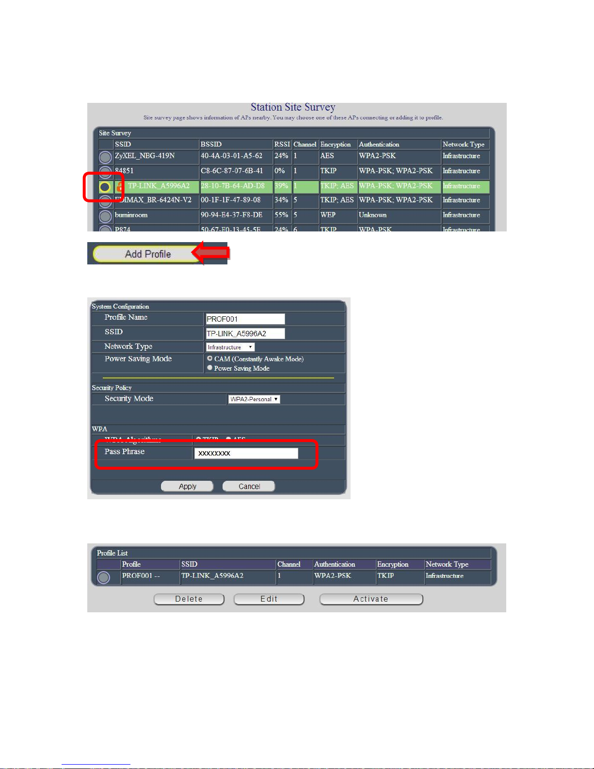
1) As go to WiFi Survey page, there is a list for the available WiFi router near 9258W2 .
Please select the one plan to use and click “ Add Profile “
9258W2 will auto get the most information of user router and user just need to type the
password to connect with the WiFi router then click “ Apply “
Then user can get the router information in “ Profile list “ section as following pictures
Select the router and press “Activate “
- 22 -
Page 23
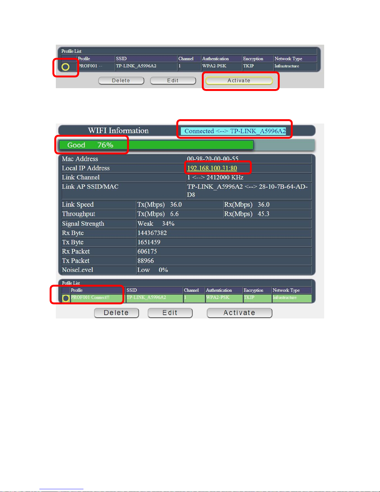
As connection successful , the page will turn to “WiFi Information “ and show the information .
Now user can see the new WiFi IP address which can be found by software IPEDIT.
Then user can remove the LAN cable and re-log in the 9258W2 by IPEDIT re-search of above
WiFi IP address.
Internet Setup
To connect the IP Power 9258W2 on Internet, there are two ways
Setup Port Mapping / Port Forwarding in your router. Please check your Router owner’s
manual .
Use software “ IP Power Center “ : Please refer to owner’s manual in CD of 9258W2 .
- 23 -
Page 24
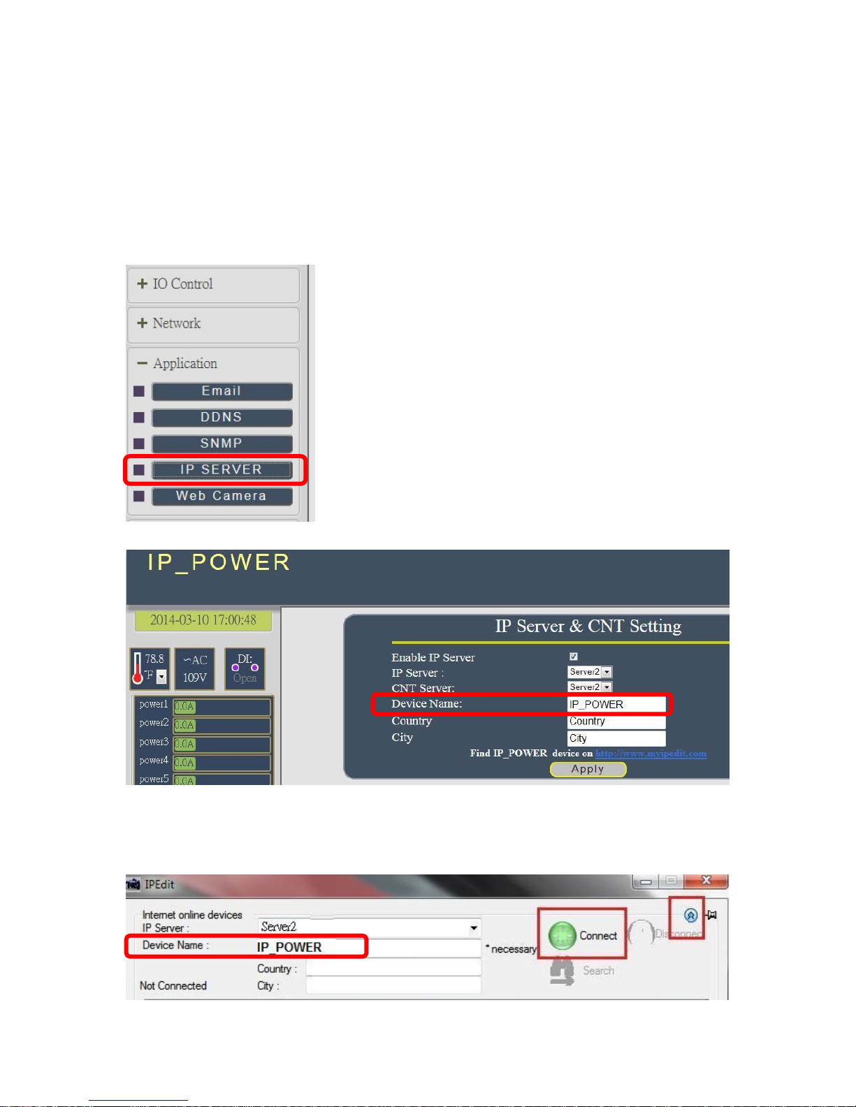
Using IP Server
IP Server is a function which allows user to search for the device easily without having to
remember long complicated IP address. Instead, if user know the device’s name of user IP
Power device and user can easily find IP Address with IP Service. To log in the webpage of
9258W2 on Internet , user still need to do the “Port forwarding “ in own router.
Before using “IP Server “ , please change the device name of user 9258W2 to avoid
similar name in host server.
1.) Open IP Edit and select the server that user 9258W2 is designated to.
2.) Hit the Green Connect button on the top of IP Edit.
- 24 -
Page 25
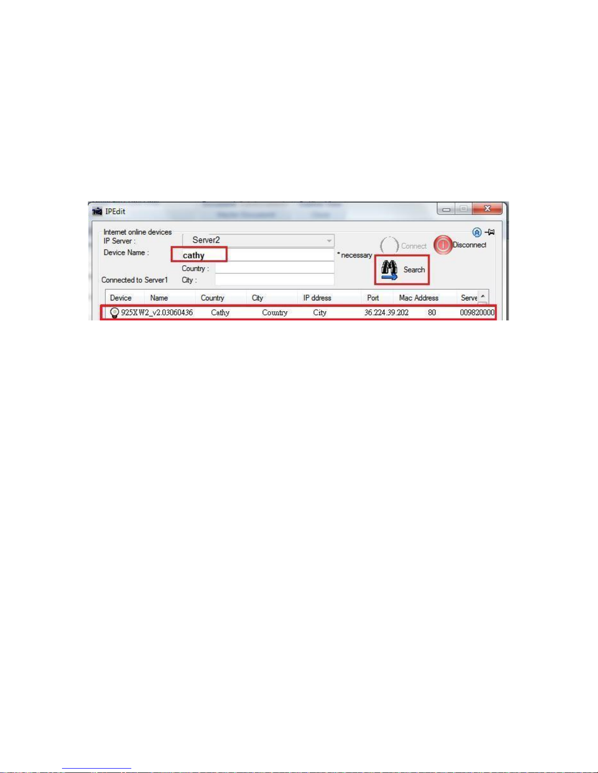
3.) Then type in the 9258W2 Name that user have selected for the device and press the Search
button.
4.) Find user device and double click on the screen and a IE window will pop up connecting to
user device. *User device must be Port Forwarded for the login screen to appear.
EX: The 9258W2 device name as Cathy , and user can search the device easily after log in the
webpage and change the default name from “ IP_POWER ” to Cathy
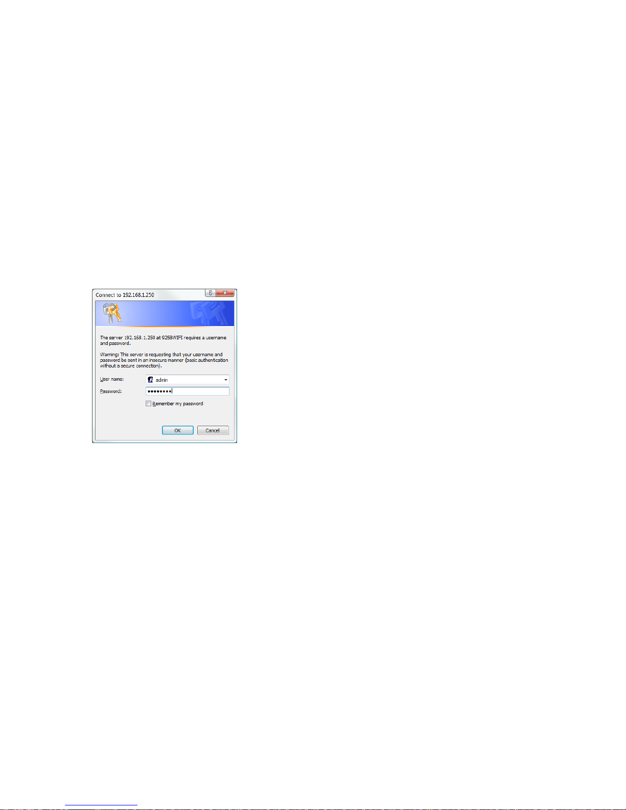
5.) After user have connected to user device, type in the Login and Password for user device
- 25 -
Page 26
Web Interface
Connect to your Device
Once the 9258W2 has been setup correctly, log into the device.
First Option
1.) Go to IP EDIT find the device that is being used
2.) Double click on the device linked and an IE window will appear with the loading screen
Second Option
1.) Open Internet Explorer type in the IP Address of the device followed by the : sign.
For example: http:192.168.122.188:9258
192.168.122.188 – IP Address
2.) Once you have typed in the IP address of the 9258W2 and it is ready to use.
The default username and password for the 9258W2
Username : admin
Password: 12345678
The Control Console
The Right Menu of the Web Interface control the functionality and setup of the IP Power 9258W2.
- 26 -
Page 27
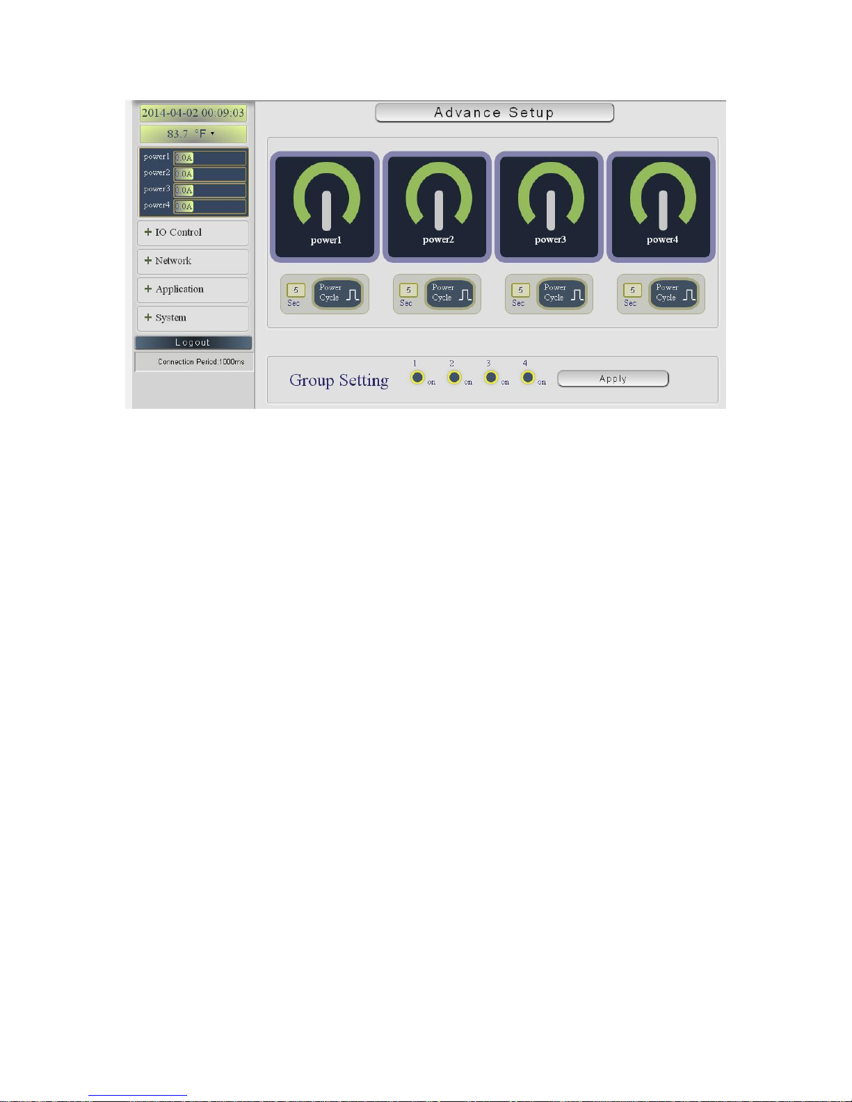
The IP Power 9258W2 Console consists of six main sections which will be explained in details
below.
Device name & Hide or Display the left setting column ( for smart phone control )
Information : Time , Temperature , Voltage , Outlet name & Current Amp value .
IO Control : Controls , Schedule, Ping, Time Line & History
Network : Setting , WiFi Info , WiFi Survey & WPS
Application : Email , DDNS, SNMP, IP Server & Web Camera
System : Management, Sys Information, Sys Log & Firmware
Logout
Connection Period
- 27 -
Page 28
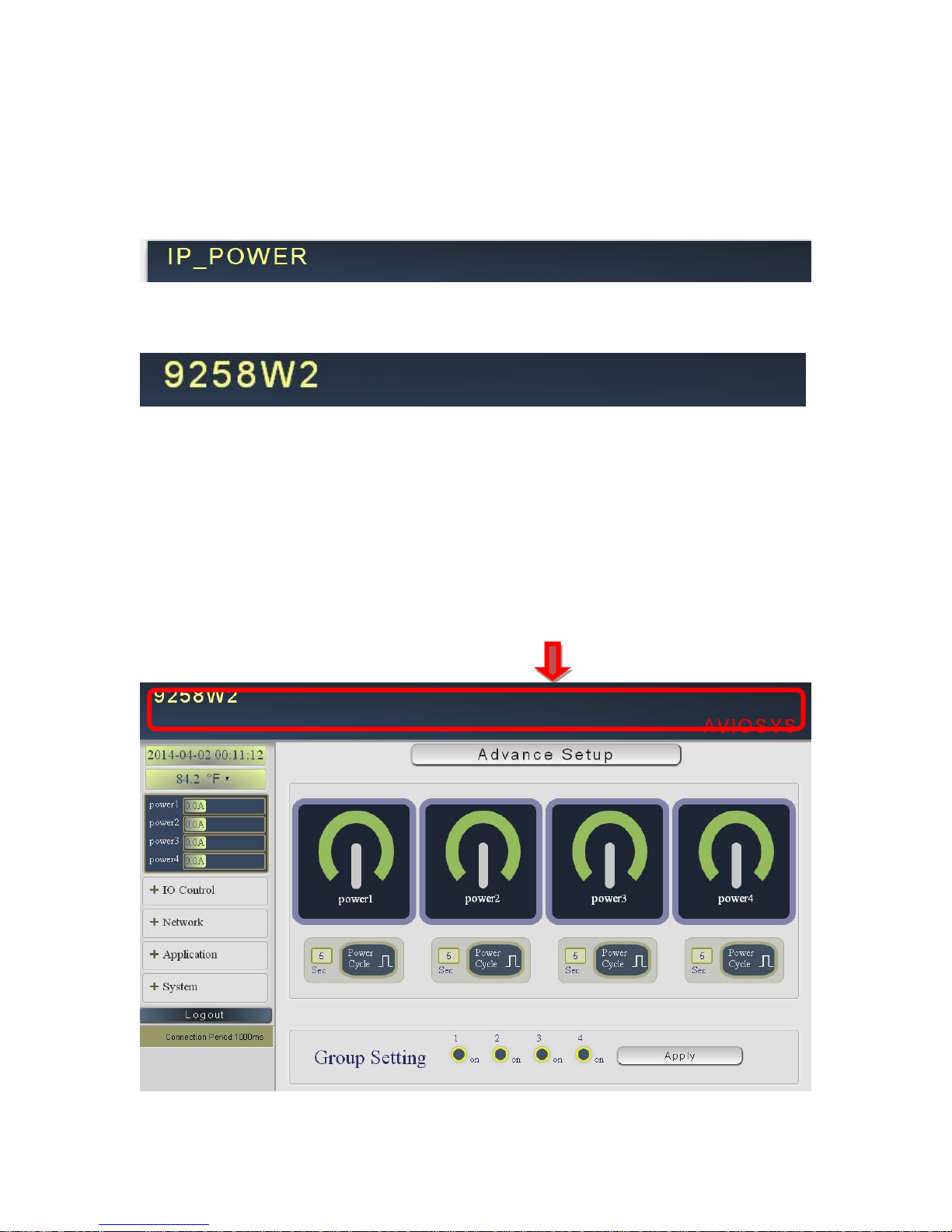
Device name
This section show the device name
Device name
You can change the device name here : Application IP Server Device name
Change name “ IP POWER 9258W2 “ as “Enjoy 9258W2 “
Please change the name in English only and do not use symbol like !@#$%^&*()_+
Display or Hide the left setting section :
For smart phone user to control 9258W2 easily , user can select to show or to hide the left
control section by pressing the blue area near device name for smart phone control :
- With left control section :
- 28 -
Page 29
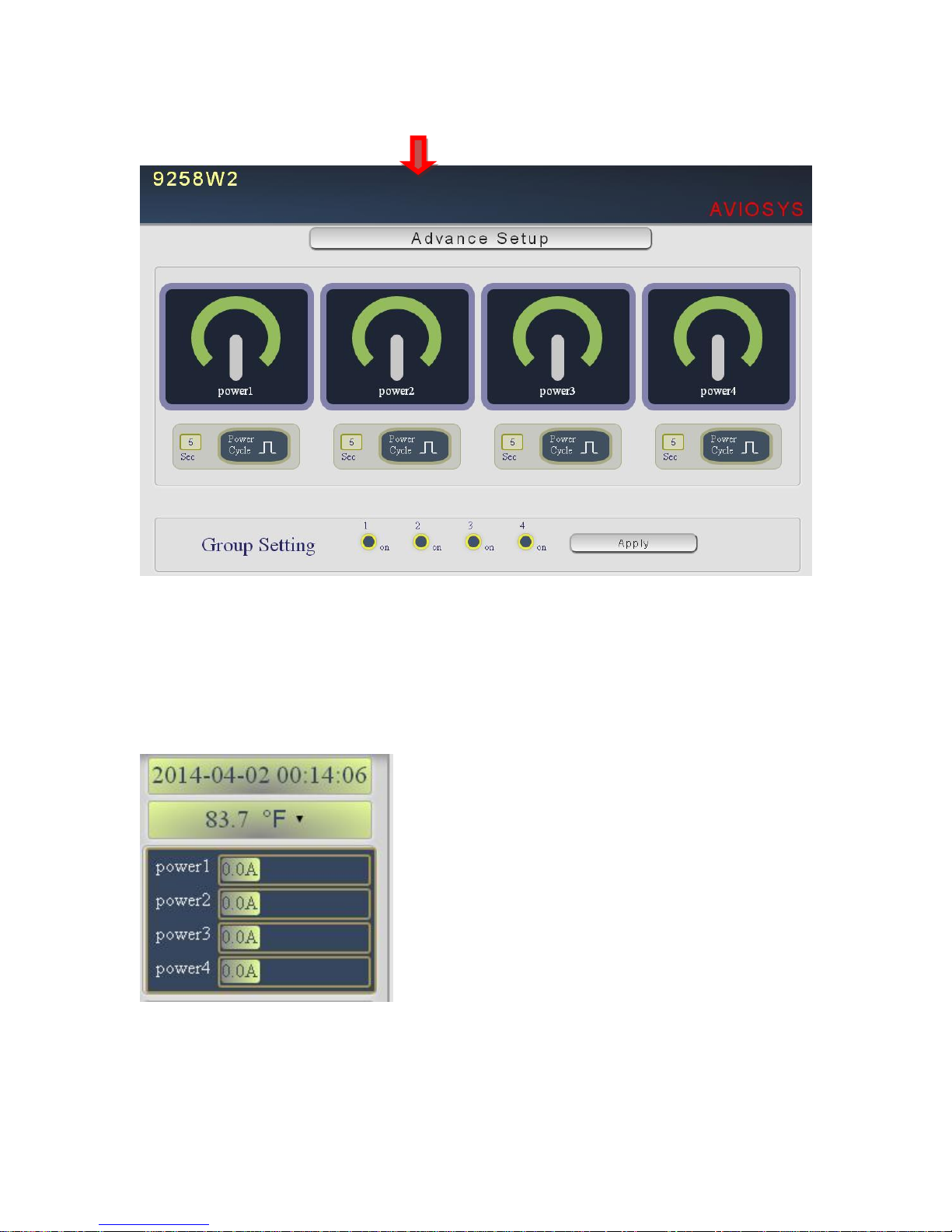
Without left control section :
Information :
In this section, there is information of Time, Temperature , Outlet name & Current Amp value .
- 29 -
Page 30
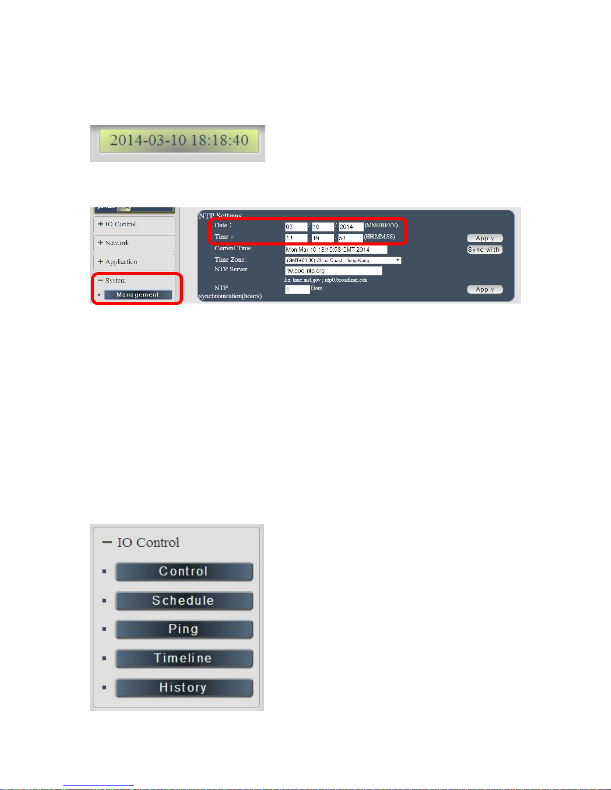
Time :
This section showed the time.
To setup the time , Please go to “ System Management NTP Settings “ , please press
“Apply” to save the new setting .
Temperature , outlet name & Current value :
This section showed the Temperature , outlet name and consumed current ( ampere) of each
power . User can change the temperature standard as ゜F or ゚ C . ) ( F = Fahrenheit , C =
Celsius ).
IO Control :
The IO Control Section allows you to directly / automatically control the outlets of the 9258W2 as
well as schedule daily, weekly, and monthly power cycles.
There are 5 section : Control , Schedule , Ping , Timeline and History.
- 30 -
Page 31
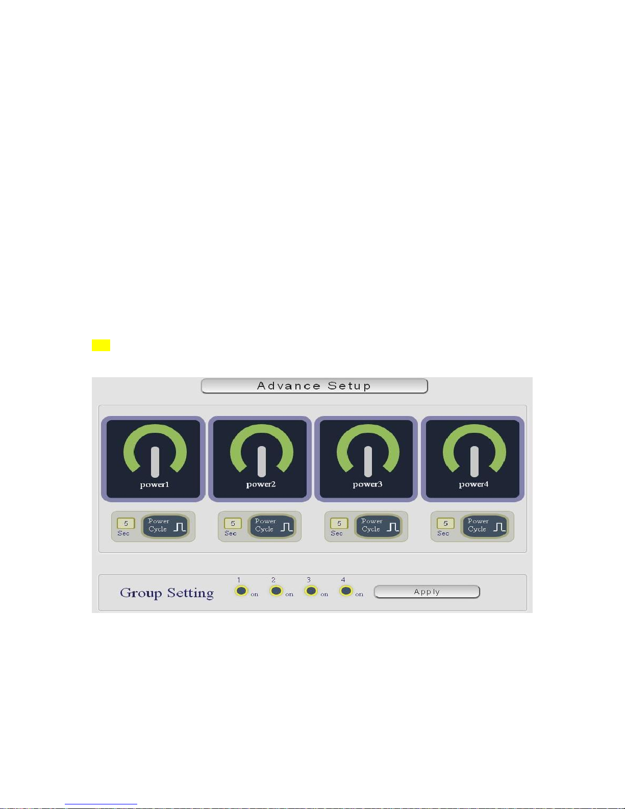
Control
There are 2 setting pages in this Section. One is “ Power Control “ and another one is “Advance
Setup “
A. Power Control :
User can do the following 3 basic operation in this page :
1. Manual control each port ON or OFF directly by pressing the power sign.
2 Power cycle : This section allow user to setup the output Reset action.
The cycle time from OFF to ON can be set from 1 to 99 seconds
- Original Status as ON : Press “Apply” then the outlet will turn OFF ON .
- Original Status as OFF : Press “Apply” then the outlet will turn ON OFF ON.
3 Group Setting : User can control more than one outlet by press the right side “Apply
“ button . For safety concern , each port of 9258W2 will turn ON or OFF one after one .
For example : The following pictures means that Power #1 & #4 is ON , Power #2 & #3 is OFF
- 31 -
Page 32
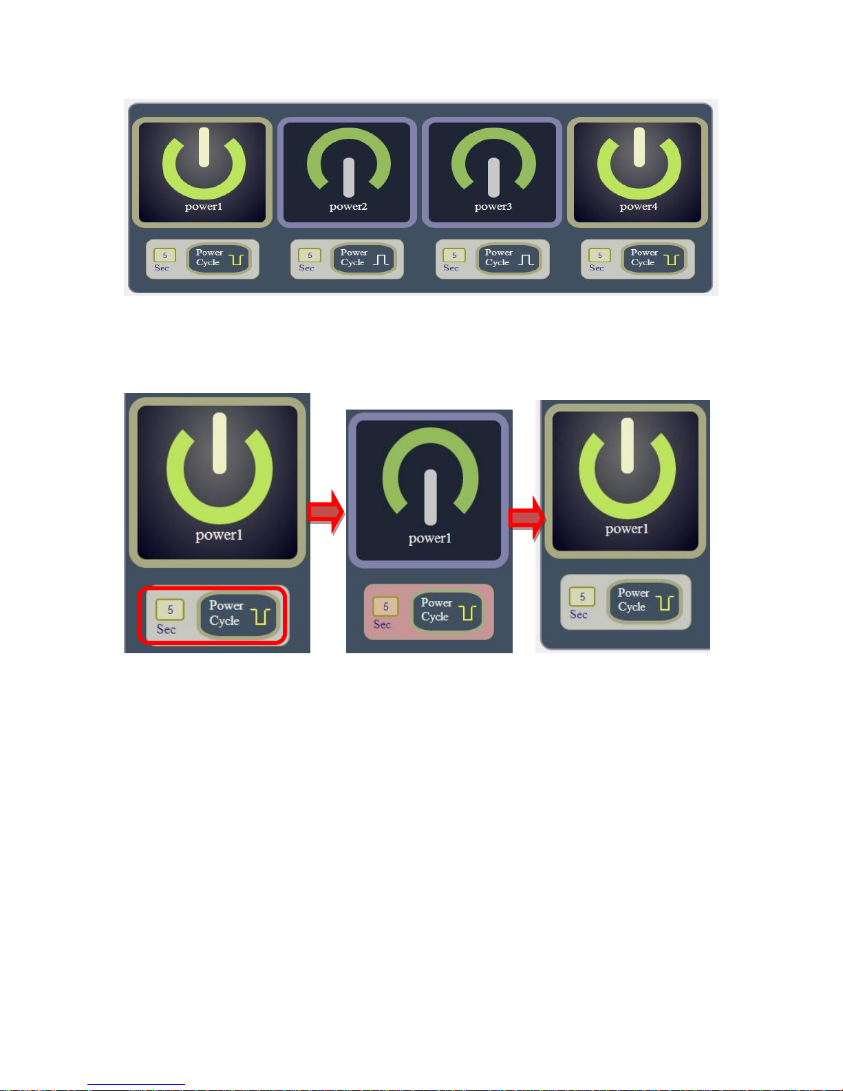
The following 3 pictures shows that after press the power cycle with 5 seconds setting , the
outlet “ Power1 “ will to turn off for 5 seconds and then turn ON . The power cycle action will
execute after press the “ Power Cycle “ button .
B. Advance Setup :
User can do the following 4 advance operation in this page :
1. Advanced Setup :
Email Alarm Setting :
Use can enable /disable the email alarm here .The email alarm section allows 9258W2 to notify
user by following situation :
- Receive Email with Current , Voltage & Temperature info. as 9258W2 device boot
up.
- 32 -
Page 33
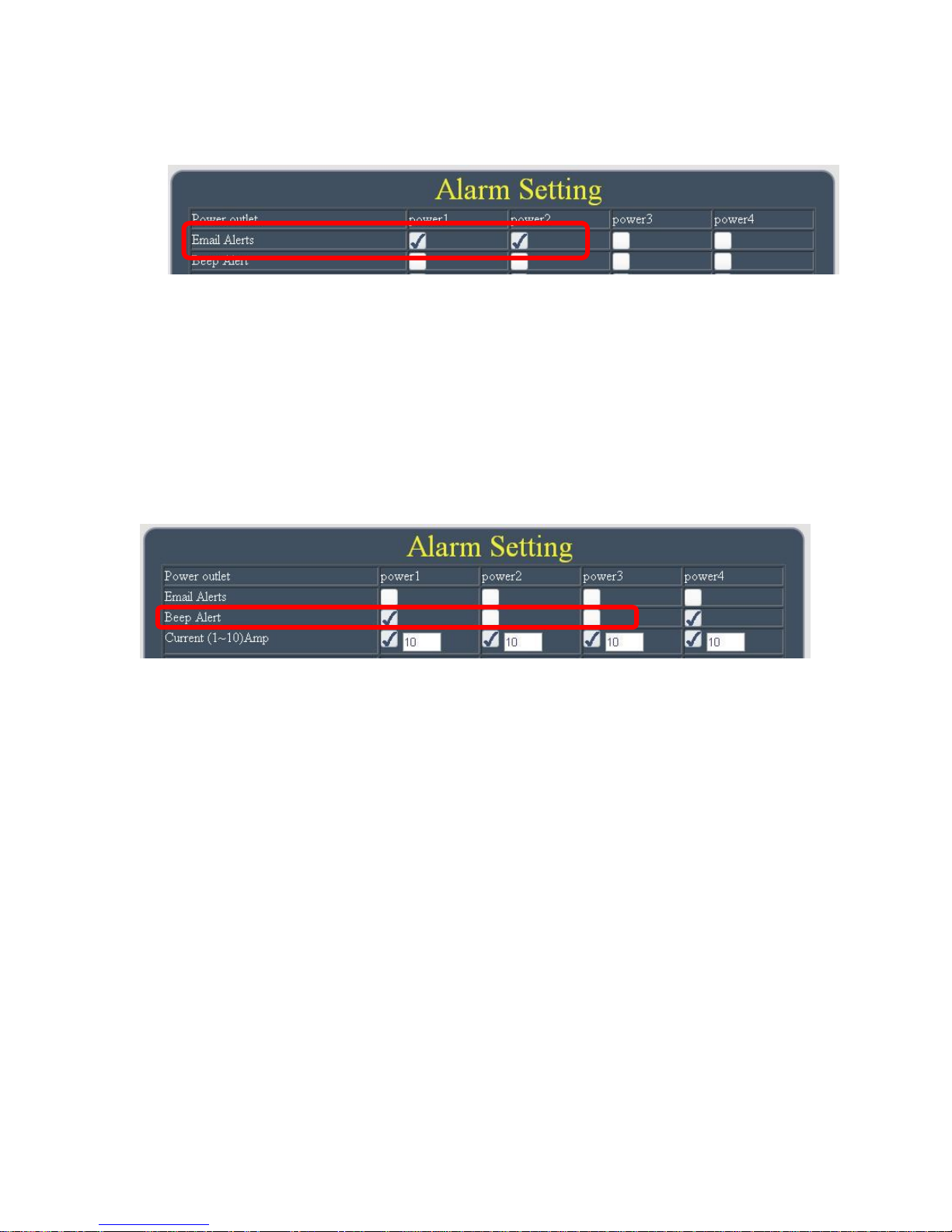
- Email alarm as over setting at Current , Voltage and temperature.
To get Email about of power status , please go to “ Application Email.
User can get email advice for the ON/OFF change of each outlets.
Beep Alarm Setting:
User can setup the operation beep ( short time beep) sound here.
Notice : The keep beeping sound can not be turn off if over limitation.
Current limit:This section allow user to enable the protection as over current and setup the
maximum value. The range of each outlet is 0~ 10 amp . As over the setting value, 9258W2
will keep beeping for several times and then turn OFF the power output automatically.
Temperature limit:This section allow user to enable the protection as over temperature and
setup the maximum value of temperature. The range is at 0 ~ 100 ℃ / 32 ~ 212 ゜F . As over
the setting value, 9258W2 will keep beeping for several times and then do the setting
ON/OFF/None by user.
Over Current Protection ( Max. Current limit )
There has “ over current protection” in 9258W2. As the Amp value of power number is over the
setting or over the maximum value 10 Amp, 9258W2 will automatically turn off that power A in
few seconds . There is an alarm with beep sound and via e-mail advice as over current. The
alarm can be enable or disable for each power in Alarm setting of Power Control in IO Control
section.
- 33 -
Page 34
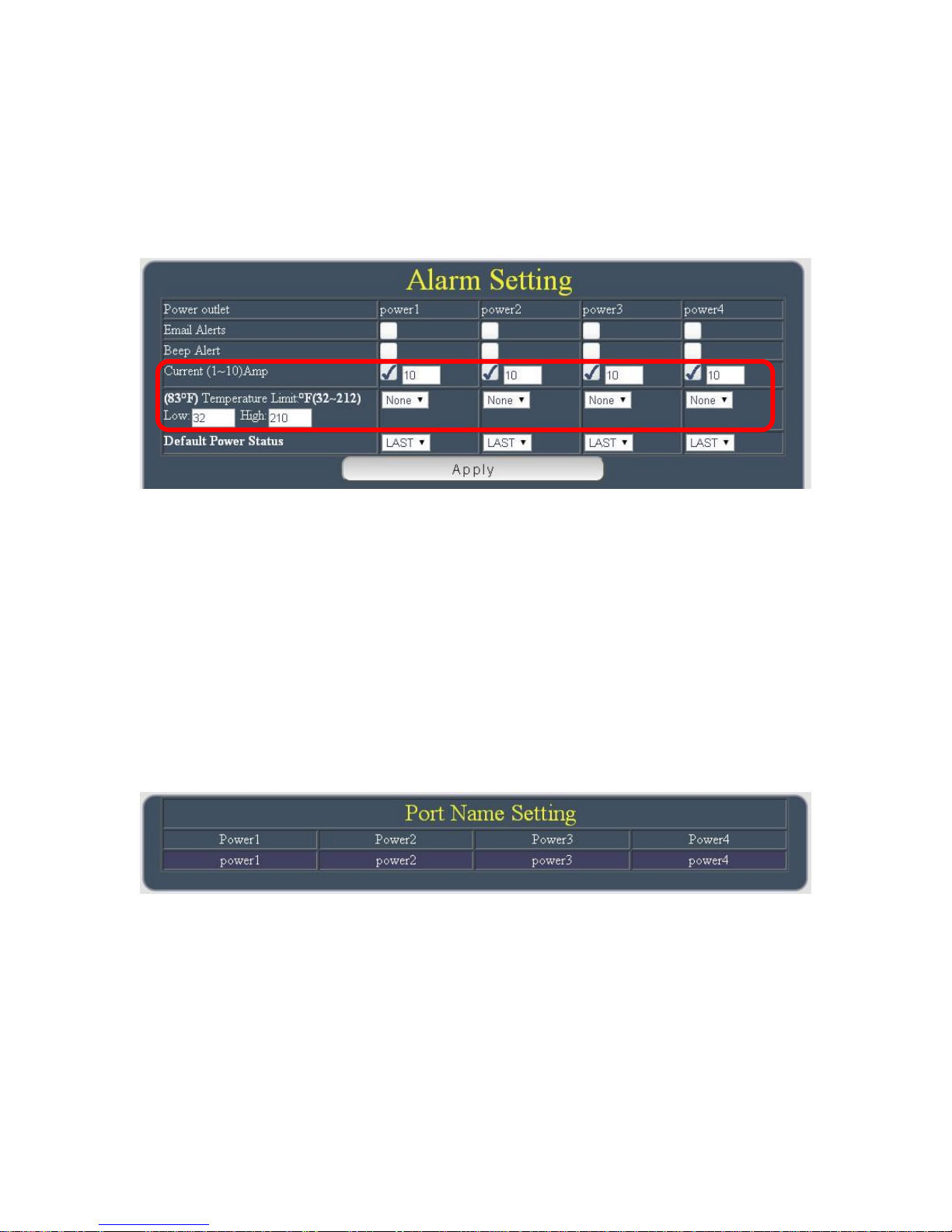
As the detected Amp value is over the current limit setting, 9258W2 will keep short 2 beep for
several times to remind the over loading issue happened and then turn off that output after a long
beeping .
After click “ Apply “ , the webpage will refresh and user can see the final setting result.
For safety concern , each port of 9258W2 will turn ON or OFF one after one
Default Power Status : The control section allow user to set the power status on ON or OFF
or LAST when the device power Reboot . The output will be same status as choose LAST
before the device power turn off.
To save the setting here , please click “Apply “ button .
4. Port Name setup
User can name each power by click the name above the power button
The number of character is 12 characters and Please change the name in English only and do
not use symbol like !@#$%^&*()_+
Note : Please change the name in English only and do not use symbol like !@#$%^&*()_+
- 34 -
Page 35
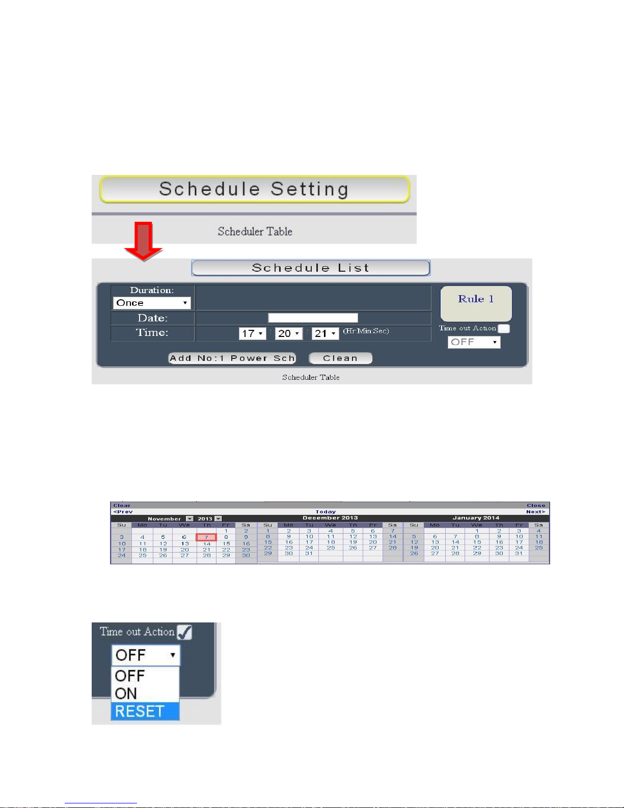
Schedule
In this section , user can see the setting schedule list first up to 29 rules . To setup each
schedule , please press “ Schedule Setting “ , then user can get the “ Schedule List “ page as
following :
Please Click the button to switch between “ Schedule Setting “ & “ Schedule list “ :
The schedule allows you to control the power outlet or turn ON/ OFF/ RESET at assigned time
Adding a scheduled event
1. Select the action Duration :
There are 3 setting - Once , Every Day . Every Week
2. Select the Date by click the space and it will shoe out the calendar
Select a specific date range where the device will repeat the desired actions during the
time specified.
3. Select the Time period.
4. Choose the Action : Enable power # by chuck in the square , select power action as
- 35 -
Page 36
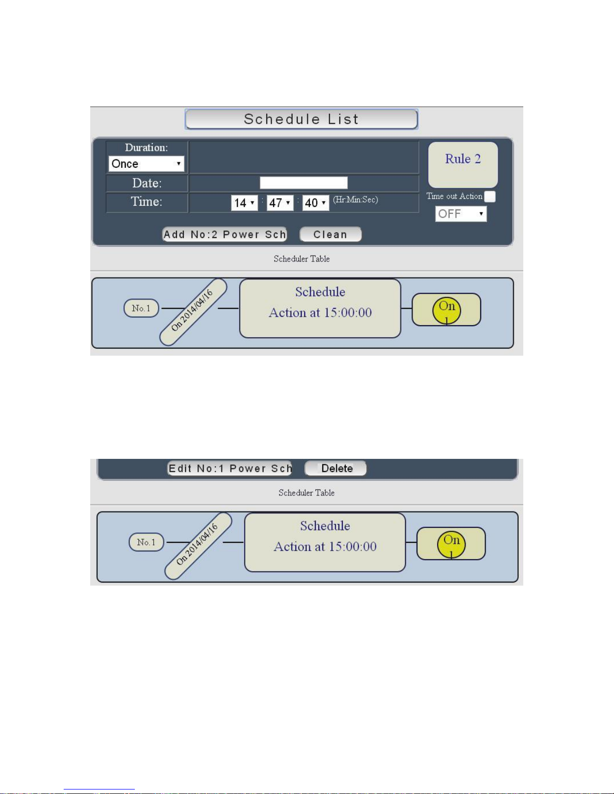
One the scheduler has been setup , hit the “ ADD No.:X Power Schedule “ button and you will
see your setting located on the bottom of the Action section .
Edit a schedule event :
Step1 : Please select the Rule you want to edit in Scheduler Table. Then the button “ADD No.:X
Power Schedule “ will switch to “Edit No.:X Power Schedule “
Step2 : :Change the setting like duration , date , time and action.
Step3 : Press “ EDIT NO. X Power Schedules “ button to confirm the setting and you will see
the page refresh and new setting display in Scheduler list
Delete - Click “ Delete “ button to remove a rule form the list .
- 36 -
Page 37
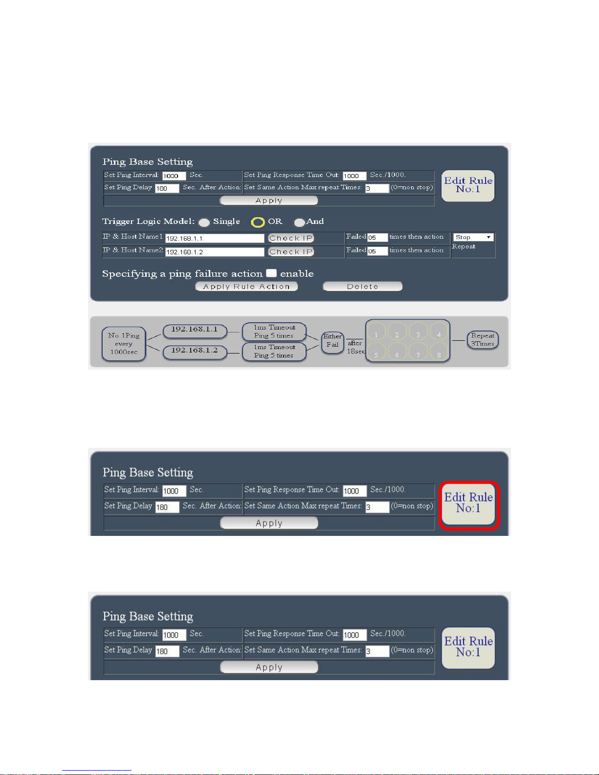
Ping
The ping function allows the device to automatically Ping an IP Address to act as a watchdog to
make sure the device getting Pinged is working properly. Please Click the button to switch
between “ Ping Setting “ & “ Ping List “ . User can hide the setting section by press “ Ping List “
There are 4 rules for Ping .
There is 3 section of the setting area :
1. Setting Rule numbers :
User can click to select different rules numbers at the right side button “ Rule No: X “ as
following pictures . There is 8 rules available.
2. Ping Base Setting :
- 37 -
Page 38
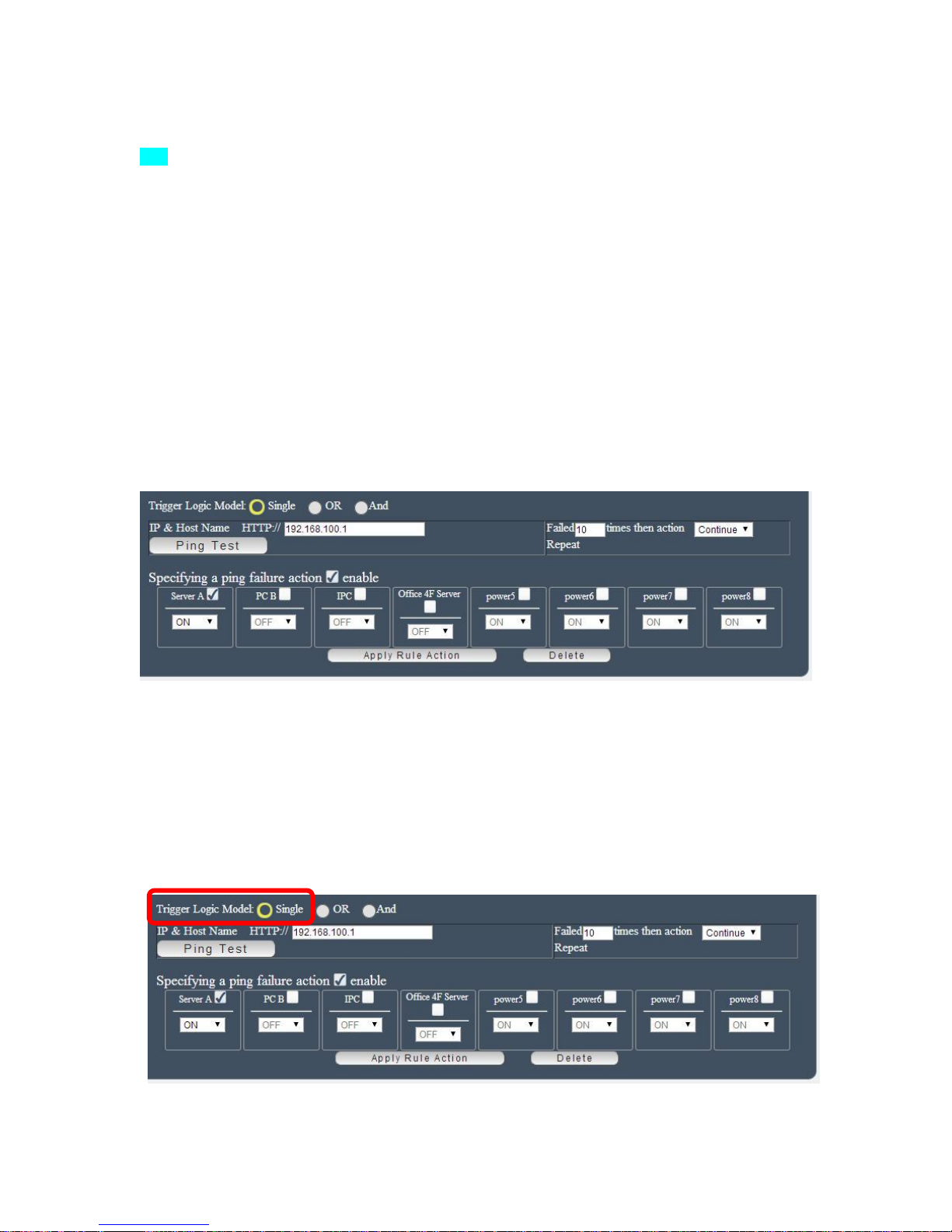
Set Ping Interval (Seconds): The number of seconds between each ping .
Set Ping Response Time out ( Sec. / 1000 = Milliseconds): The number of milliseconds the
device will wait for a response from the pinged device if no ping is detected within this time it
will be considered a ping failure.
Set Ping Delay XXXXX Sec. After Action:After ping finish , do the action after setting
second
Set Same Action Max repeat Times:Set the times to execute the Ping Failure action
Set 0 means action non stop - Keep action & no limit times.
As finish setting , please click “ Apply “ to save the setting in this area , the webpage will refresh
and user can see the final setting result. Ten set up different rules for different port .
3. Other Setting :
The setting here is for each rules.
Trigger Logic Model :
User can select the action activated by one / two IP Host failure or either one fail
- Single : Execute Action by one IP Host failure .
- OR : Execute Action by either one IP Host failure as setting 2 pcs IP Host
- And : Execute Action by both IP Host failure as setting 2 pcs IP Host
Single : 9258W2 will Ping one IP address. As the IP fail times up to the setting times .
Action (ON/OFF/RESET) will be activated .
- 38 -
Page 39
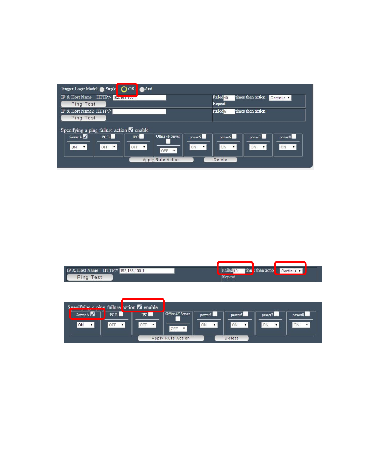
OR : 9258W2 will Ping 2 IP address. Either one IP fail times up to the setting times.
Action (ON/OFF/RESET) will be activated .
AND : 9258W2 will Ping 2 IP address. Both IP fail up to the setting times.
Action (ON/OFF/RESET) will be activated.
IP & Host Name : Input the IP Address ( ex: 122.116.123.138) or Host - web address
( ex: www.google.com) user would like to ping.
User can use the “ ping test “ bottom to check the address valid or not
Failed times : Setup the ping failure times for 9258W2 to execute the setup ON/OFF /
Reset action of each port ..
Repeat : After the ON/OFF/Reset action , user can setup the Ping action to keep ping
( Continue ) or to Stop Ping ( Stop) .
Enable Ping function : In the selected Rules number , please select the outlet number power
to activate as ping fails and then press “ Apply Rule Action “ button to confirm the setting .
Ping failure action :
When the number of Ping Failures times have been reached. The device can be set to “ ON ,
OFF or Reset “ function
Reset: Can set up the time gap of OFF to ON. The “ Sec “ section is for action as Reset only.
- 39 -
Page 40
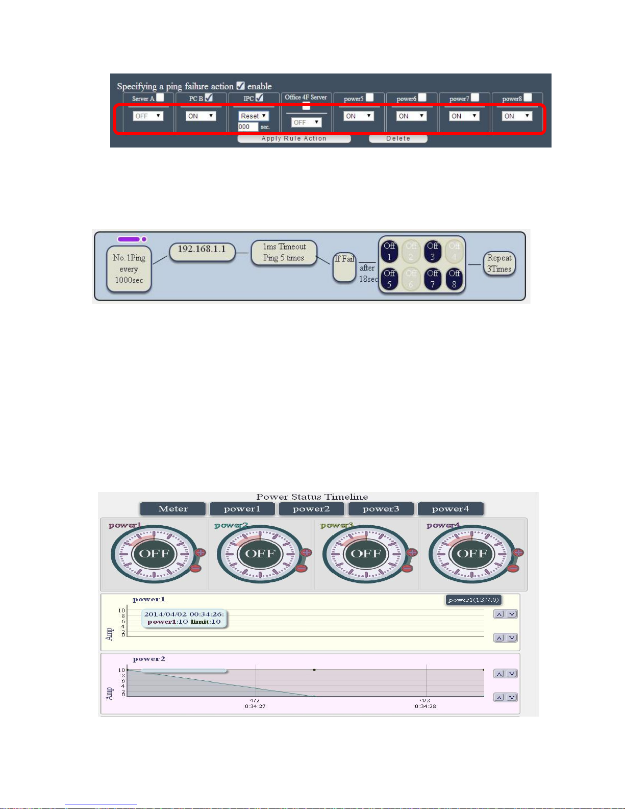
Select the action as ping failure as no responding. The number of ping failures before the Action
is activated. The setting times rage is 1 to 99. Select the number of Ping Failures that user would
like to occur before the action is activated. The reddish pink number to the right represents the
actual number of ping failures. Keep in mind that four consecutive pings equals to 1 Ping failure.
EX: Result of setting
Timeline
To see this section display normally, please do use IE9.0 or above, Firefox,
Google Chrome or Safari and set resolution at 1280*768 .
This section is for monitor the Ampere ( =Amp ) value each power consumed and is for setup the
maximum value of each power . The maximum Amp of each power is 10Amp. User can click the
“Up / Down “ button directly to change the maximum Amp value of each power.
There is information board show “ Time, Current Limit , Power name and the value of consumed
current “ as move the mouse in the chart .
- 40 -
Page 41
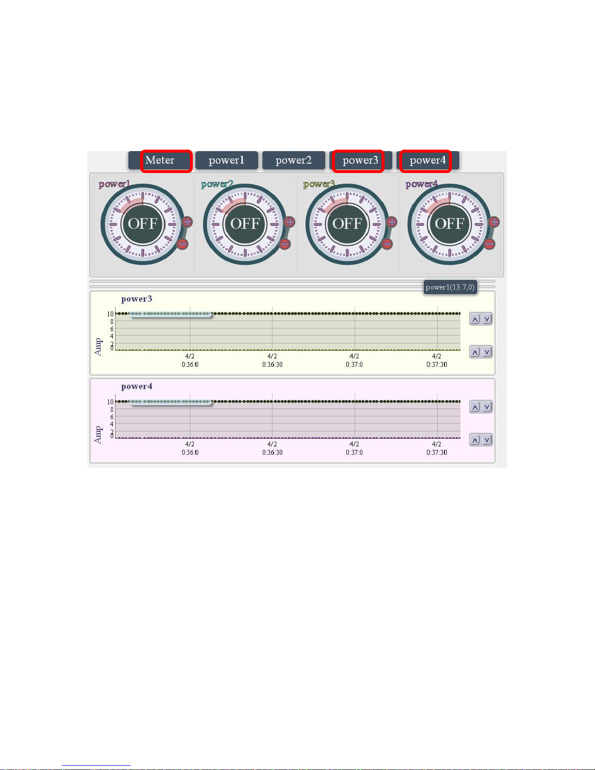
Display Interface:
A. Display chart : User can select the chart which can be display by pressing the top 5
buttons : Meter , Outlet 1 , 2, 3 & 4
Ex: Select Meter , Outlet 3 & 4 :
- 41 -
Page 42
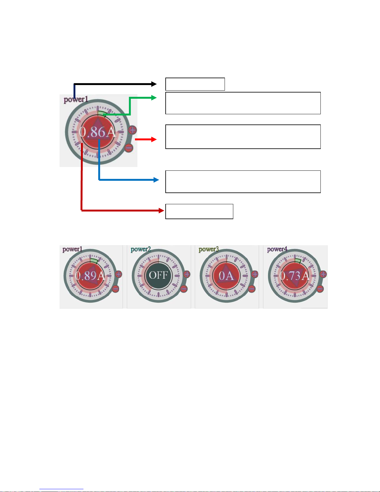
B. Meter section :
Green area: Consumed current
It showed 1Amp in this picture.
Channel Name
Current Amp display and control On/Off.
If showed “OFF” , it means the outlet is turn off
+ - : Press + or - to directly adjust the max.
current limit. Range at 0~10amp
Max. Current limit.
In this section , user can get the channel name , the consumed current of each port show in
chart & in word , and setup the max. limit current of each output directly.
B-1 : In the following chart , it shows different of the max. limit of current .
Power 1 : Max. current limit as 3 amp. The consumed current now is 0.89A
Power 2 : Max. current limit as 7 amp. The consumed current now is OFF
Power 3 : Max. current limit as 6 amp. The output is turn ON .
Power 4 : Max. current limit as 2 amp. The consumed current now is 0.73A
Note : If the detected current output power 1 is over the max. limit current value setting,
then power 1 will turn off automatically in few second .
C. Curve Chart section :
In this section, user can see the consumed current value in black spot and the with live update
chart while time past show from time to time .
- 42 -
Page 43
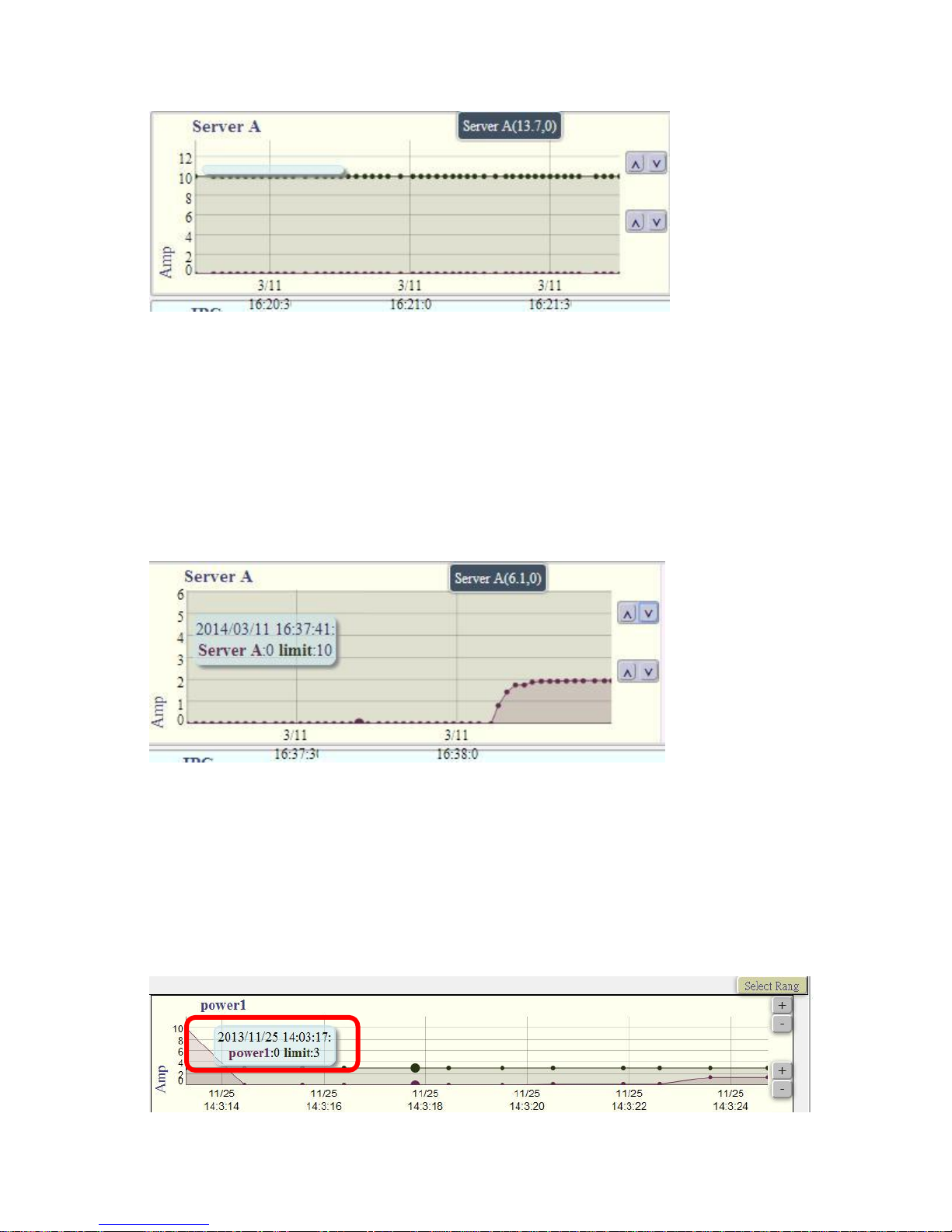
- X axis - horizon , it show date and time .
- Y axis – vertical , it shows current value in ampere of each port .
- Light Blue Bar at left : Show the date , time , outlet name and limit information .
- Dark Blue Bar at Right : Show the max. & min. value of current limitation for alarm.
- Right side buttons :
The above 2 buttons are to control the Maximum value of X axis.
The below 2 buttons are to control the Minimum value of X axis.
User can see the consumed ampere from past 60 seconds in the chart in color spot line - each
outlet had different own color
And there is information at the right side to show the port and value user are setting
C-3 User can also change the time gap by mouse selection : Select the time area user
would like show on chart . To go back to original display as 10 seconds , please click “Current
Limit” of IO Control section at left area .
After select the range the X axis will be display the time range user just select .
C-4 As mouse move to the line chart , there is message board shows time, current and
consumed power current in a square as following:
- 43 -
Page 44
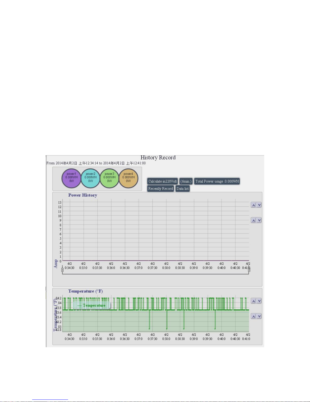
History :
To use this function , please do setup the Time first .
To see this section display, please do use IE9.0 or above or Firefox . and set
resolution at 1280*768 .
There are 4 sections in this section:
- Time period
- 4 color Round signs & consumed power WH & W ,
- Voltage select , Duration Time , Total Power Usage, Recently Record , Data list ,
- 2 line charts : Power History and Temperature.
Note 1 : The history will be deleted after device power Reboot .
Note 2 : To use “History , please do setup the time in “ System Management “ to make
sure the calculate start time correct .
- 44 -
Page 45
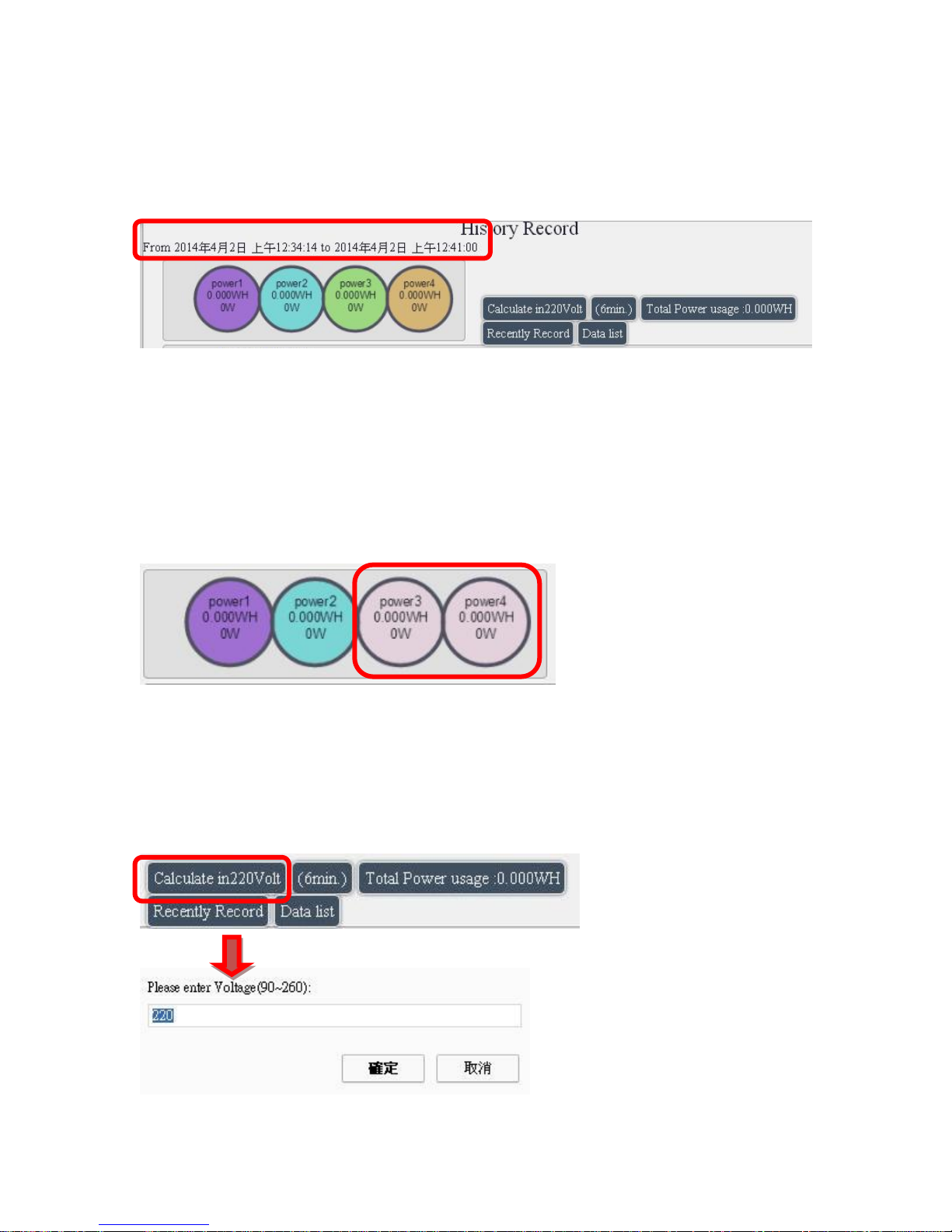
A. Time period
It show the calculate time period for the 3 chart :
Power History of each outlet , Voltage and Temperature.
B. 4 Round signs & Line Color information :
User can select the 4 round signs represented output 1 ~ 4 to display the power usage history
line of each port and total 4 ports.
As select all 4 signs to display , the right section show the 4 line colors of each port and also the
line of total current consumed. If not select any one port , each round sign show no color and the
right section only show the total current consumed .
For example : Only show Outlet #1 & 2 , the unselected outlet will show lite purple as following :
As the mouse move in to the power chart range, the consumed current of each outlet and the
total ports show at right section :
C. Voltage select , Duration Time, Total Power Usage , Recently Record ,
Data list
- Voltage Select :
- 45 -
Page 46
- Duration time & Total Power Usage :
Show the time period for the power usage it show the power usage ( WH – Walt per hour) at
some period of Time ( time length and date range ) of the “ Power History chart “ chart
- Recently Record: click to switch between Recently, Daily , Weekly , Monthly , Yearly
-Data List : User can see the data list in this area with time, power current and temperature value
of each port . As select “ Data List “ , there are 2 section “Save “ & “Close “ shown
-Save : As click this button , there is a wizard show to save the text as file “ Timas.csv “ .
User can save the CSV file into assigned direction of user PC.
-Close : to change the display from text list back to chart .
D. 2 charts : Power Usage History and Temperature.
D-1 Power History :
The power history chart show the consumed current ( Ampere ) of each outlet in different color in
the chart. User can just click the round circle sign and show to get the current line in chart .
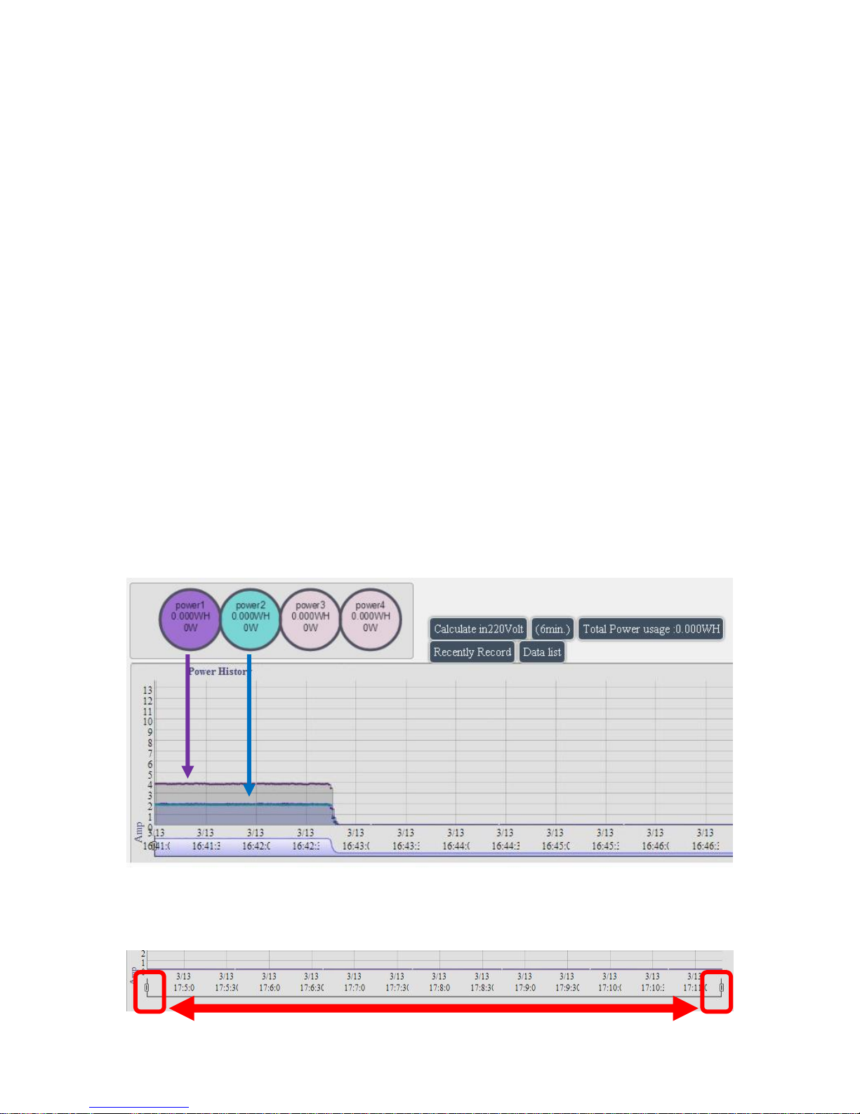
There are 8 color round signs on the top side show the total WH ( Watt –Hour) , Watt and Voltage
of each power consumption in select time.
EX: Select only Outlet 1 & 2 by click the round sign directly
To adjust the time gap of the chart, user can move the 2 time gap sign to get the total
consumed WH value of the select time range. Please refer following picture :
- 46 -
Page 47
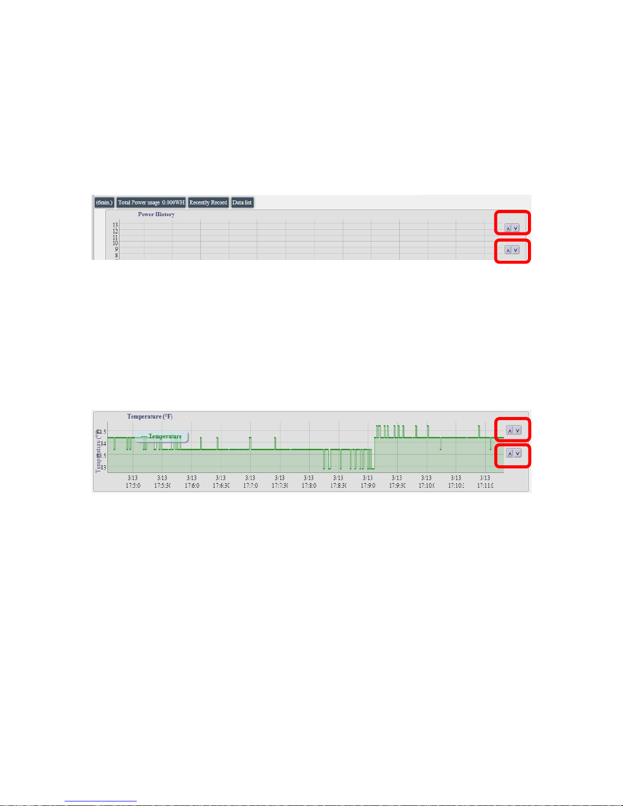
Note: The current history record will be cleared off the chart while device power off .
To adjust the Amp range at X Axis , user can move the 2 buttons at right sides
- The above 2 buttons are to control the Maximum value of X axis.
- The below 2 buttons are to control the Minimum value of X axis.
D-2 Temperature chart
The Temperature chart show the temperature near 9258W2 . The sensor is at front panel in red.
To adjust the display range at X Axis , user can move the 2 buttons at right sides
- The above 2 buttons are to control the Maximum value of X axis.
- The below 2 buttons are to control the Minimum value of X axis.
- 47 -
Page 48
Network :
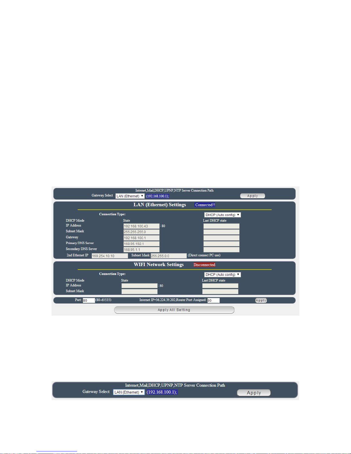
The Network Section allows user to setup LAN –Ethernet or WiFi settings and WPS setting .
There are 4 sections : Setting , WiFi Info , WiFi Survey and WPS .
Setting :
This Setting section is showed the network status of 9258W2. Please select one connect ion –
Either LAN or WiFi connection but not both connected after finish setting .
There is 4 different portions in this section :
Gateway Selection : LAN ( Ethernet ) / WiFi
LAN Settings
WiFi Network settings
Port Setting : use can set port range as 80 ~65535
Default Gateway
The gateway is the door for Internet connection , Email , DHCP UPNP NET Server .
Please select correct Gateway LAN or WAN for the user to log in 9258W2 form Internet and
use above functions .
- 48 -
Page 49
Notice :
Under DHCP mode - either select LAN or WiFi connection, 9258W2 will get the gateway
information automatically.
But if under Static mode , please do fill up the correct gateway.
As choose WiFi connection , the gateway of LAN will be empty automatically.
LAN (Ethernet ) Settings :
The network status is connected by cable . The connection way include :
Static IP / DHCP / PPPOE
In connection type , there are 3 different way for LAN - Ethernet Connection .
A. STATIC (fixed IP) :
Setup IP address manually. This allows the 9258W2 to obtain an IP Address automatically from
user`s server connected to Internet . Recommended for users need to control through Internet.
Please do fill up the correct gateway for login from Internet .
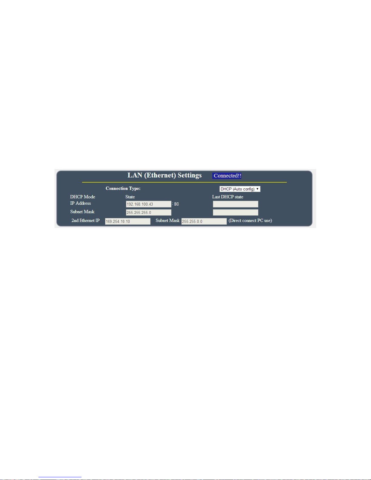
B. DHCP Mode :
Obtain IP address via DHCP model . This allows the 9258W2 to obtain an IP Address
automatically from user`s server connected to Internet. Recommended for non advance users.
User can only revise the Host Name under DHCP mode. This is also the default setting for fast
LAN connection solution.
As the IP from DHCP Service of user`s router will be changed by router . 9258W2 will remember
last IP of 9258W2 assigned by user`s router in “Last DHCP state “ for information
- 49 -
Page 50
C. PPPOE :
Only support for Ethernet connection .
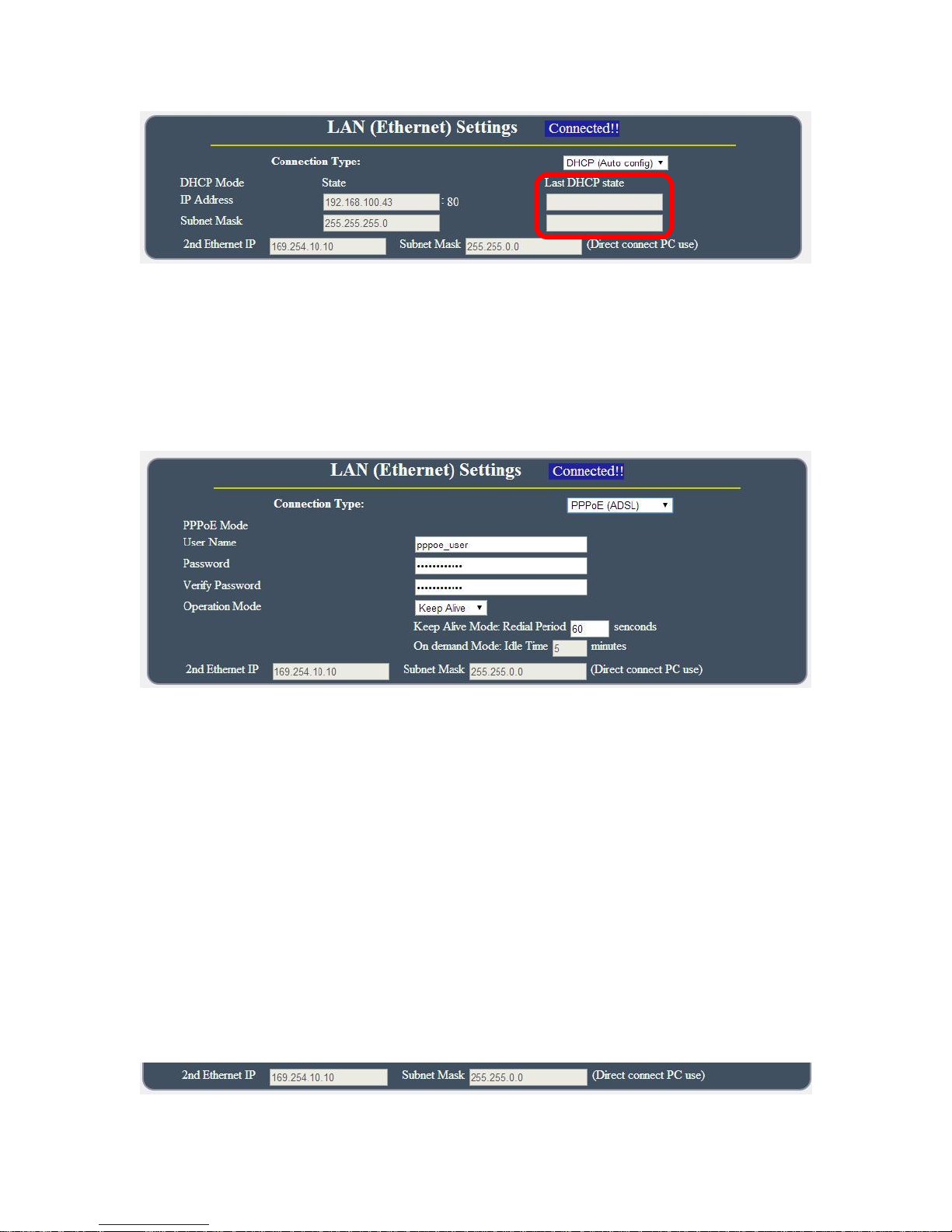
Obtain IP address via Internet Service Provider (ISP) through PPPOE service ( The IP address
can be reach on Internet but not fixed ) . User need to supply the Username & Password ISP
supply to get connection on Internet.
- User Name : Please type in the format ISP supply for PPPOE connection
- Password : Please type in the format ISP supply for PPPOE connection
- Verify Password : Re-type the password
- Operation Mode : There are 3 mode for PPPOE connection
- Keep Alive : Auto connection in the setting time as disconnect.
- On Demand : Auto connection after setting idle time as disconnect .
- 2nd Ethernet IP: The IP 169.254.10.10 here is fixed and can not be changed .
This IP is for user to connect to PC directly.
Without network connection , the IP of Win PC is 169.254.10.xxx . So the IP is
for user to connect to PC directly and user do not need to change the IP of WIN PC
connect to 9258W2 by network cable.
- 50 -
Page 51
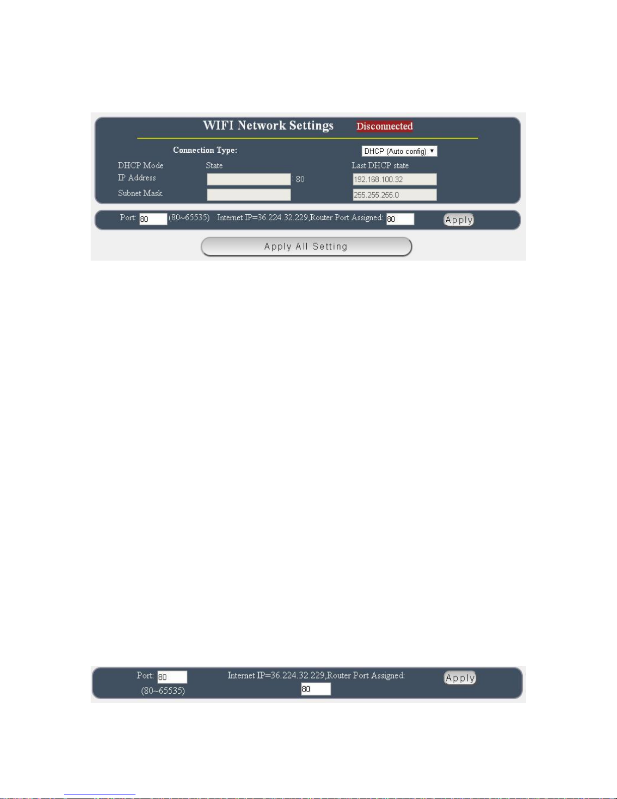
WiFi Network Settings :
The WIFI network connection support : Static IP / DHCP
A. STATIC (fixed IP) :
Setup IP address manually. This allows the 9258W2 to obtain an IP Address automatically from
user`s server connected to Internet . Recommended for users need to control through Internet.
Please do fill up the correct gateway for login from Internet .
B. DHCP Mode :
Obtain IP address via DHCP model . This allows the 9258W2 to obtain an IP Address
automatically from user`s server connected to Internet. Recommended for non advance users.
User can only revise the Host Name under DHCP mode. This is also the default setting for fast
LAN connection solution.
As the IP from DHCP Service of user`s router will be changed by router . 9258W2 will remember
last IP of 9258W2 assigned by user`s router in “Last DHCP state “ for information
Port
9258W2 will check your router IP of this connection , and you can separate the port for LAN
connection or for Internet connection .
For example : The router IP is 36.224.32.229:80
- 51 -
Page 52
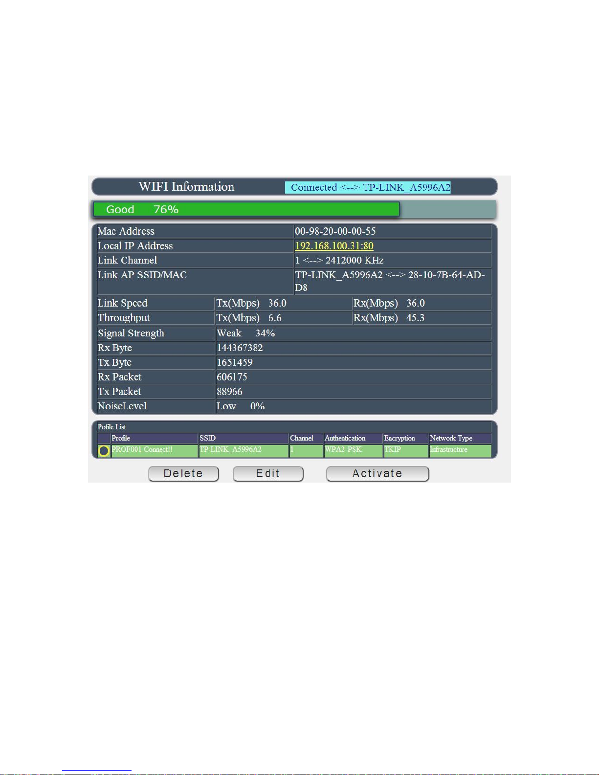
WiFi Info :
There are 2 sections in this page . One is WiFi information and another one is Profile list .
After WiFi connection successfully , 9258W2 will turn to this page and show the WiFi information .
Please refer page 19 to setup the WiFi connection. User can add different router in profile list for
9258W2 to switch. User can get the Router name , signal strength , MAC address , WiFi IP
address , Channel and most WiFi connection information in this section .
WiFi Information Section :
There are WIFi Information : Connect to the router , Singal strength , MAC & IP Address ,
Local IP Address : It show the IP of WiFi connection ( Allocate Supply by WiFi Router )
Connection Status : It show the router name of 9258W2 is connected.
If need to add other WiFi Router into profile list , please arrange the WiFi connection setup ,
please go to “ WiFi Site Survey “ but user can change the profile list to switch the WiFi Router
you would like to use.
As the connection is successful , there will be is Yellow circle mark in first column of the profile
Router. User can also edit / delete / active the router here In profile list section . ,
If need to add other WiFi Router into profile list , please select the router in “ WiFi Survey “ page
and add into profile (with correct password) . Then user can change the profile list to switch the
WiFi Router user would like to use.
- 52 -
Page 53
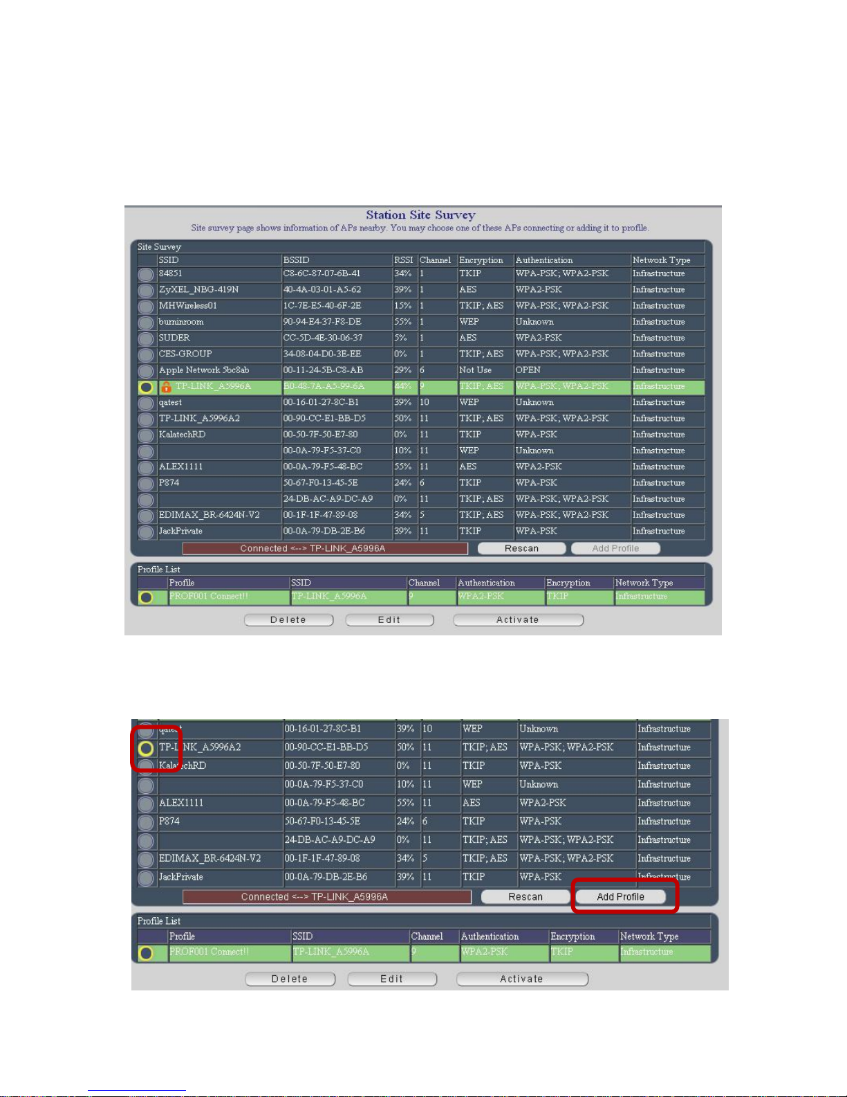
WiFi Survey
This section is to arrange WiFi connection. 9258W2 will auto search the WiFi Router nearby
and also their information as boot up , 9258W2 user can just select the router and type the
password to connect with your WiFi router and make connection easily.
Add WiFi Router into “ Profile list “ :
Step 1: Select the Router you would like to use , and click “Add Profile “
- 53 -
Page 54
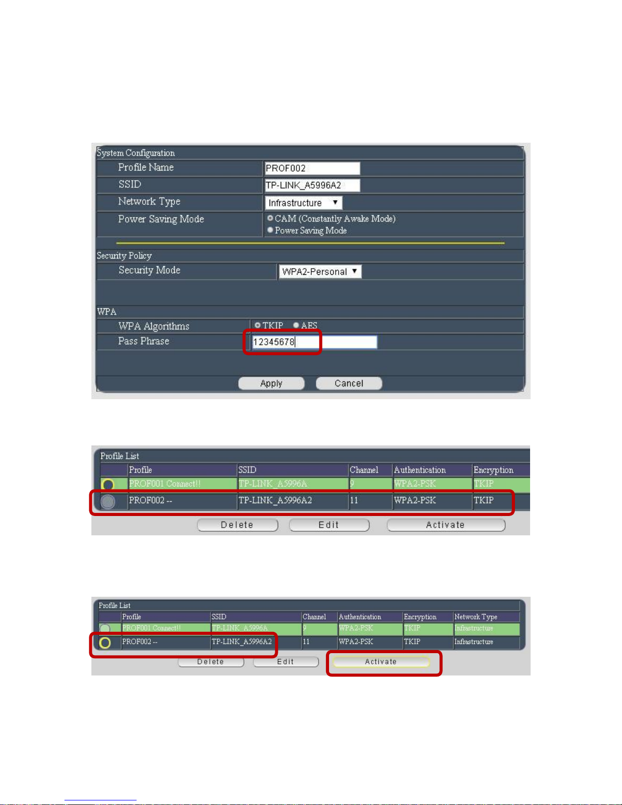
Step 2 : 9258W2 will auto get the most information of your router and you just need to type the
password to connect with the WiFi router then click “ Apply “
Then you will see the Router name add in to “Profile list “
Connect 9258W2 to this add Router : Active the WiFi Router in “ Profile list “
Please select the router an click “Active “ to make connection with 9258W2 .
Step 4 : After Active successful , you will see the IP information in “ Connection Status “ of
- 54 -
Page 55
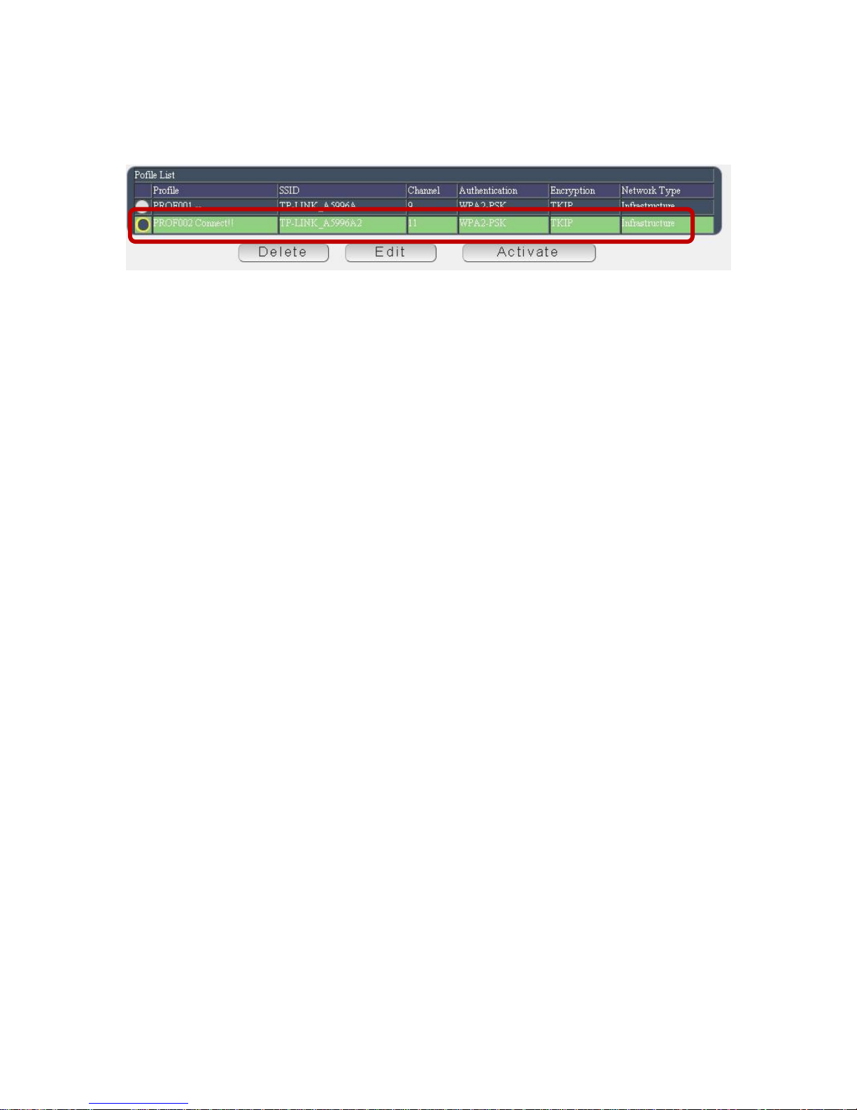
WiFi Info. Please check if the “ Local IP Address “ of WiFi Info is under same segment# with
your PC.
Notice :
# Segment : The first 9 digits of the IP Address .
EX: The IP of your PC is 192.168.100.122. If the “ Local IP Address “ at WiFi Info is
192.168.100. x ( X can the value of 1~252 ) , your PC can get into the webpage of 9258W2 .
# Please press “Rescan “ to search the router near by again if can not see your router in the list.
Delete the Router in “ Profile list “ :
Please select the router and click “ Delete “ to remove this router from “ Profile list ”
Note : Delete the Router form Pro File list do not affect the connection of WiFi.
WPS ( WiFi Protection Service )
To connect IP Power 9258W2 with WiFi router by WPS function . Please check if the router
support WPS function fist .
There is 3 way to setup by WPS : There are 3 ways to setup WPS: Manual hardware setting
connection or webpage application
The following information is for apply WPS by webpage control – without WiFi Router nearby .
- By the Reset Button on 9258W2 and the WPS button on WiFi AP ( Router)
Please refer the setup procedure in page #15 .
- By Enrollee of 9258W2 webpage and WPS button on WiFi AP ( Router)
Step 1 : Please select the WIFI AP ( Router ) you want to connect .
Step 2 : Select Mode “Enrollee “ then the page will refresh and get the PIN number
automatically
- 55 -
Page 56
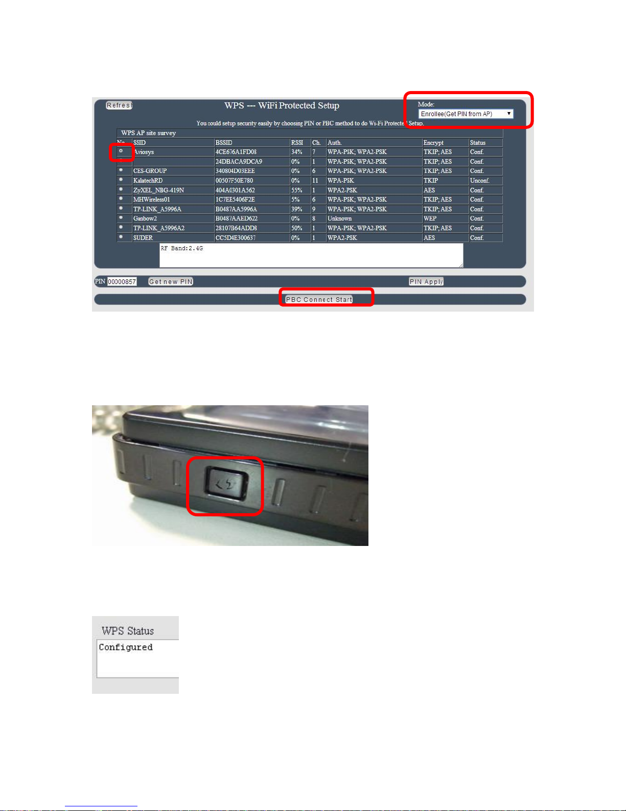
Step 3 : Press “ PBC Connect Start “ , then there is one short beep .
Step 4 : Press the WPS buttons of WiFi AP ( Router) soon in few seconds
Step 5: After few seconds , there are short 2 beeps which means WPS connection
successfully.
There are messages updated during the configuration in “ WPS status “ section :
As WPS connection successfully , there is “Configured “ message .
If user does not press the WPS function of selected AP ( WiFi Router )
- 56 -
Page 57
SCAN AP …… PCB: NO AP (one Long Beep) No Used
Which means the WPS connection fail and there is one long beep mean the connection fail.
Please try again. )
Step: 6 : User can see the WPS connection in section “ WiFi Info “ & “ WiFi Survey “ of Network
In “ WiFi Survey “
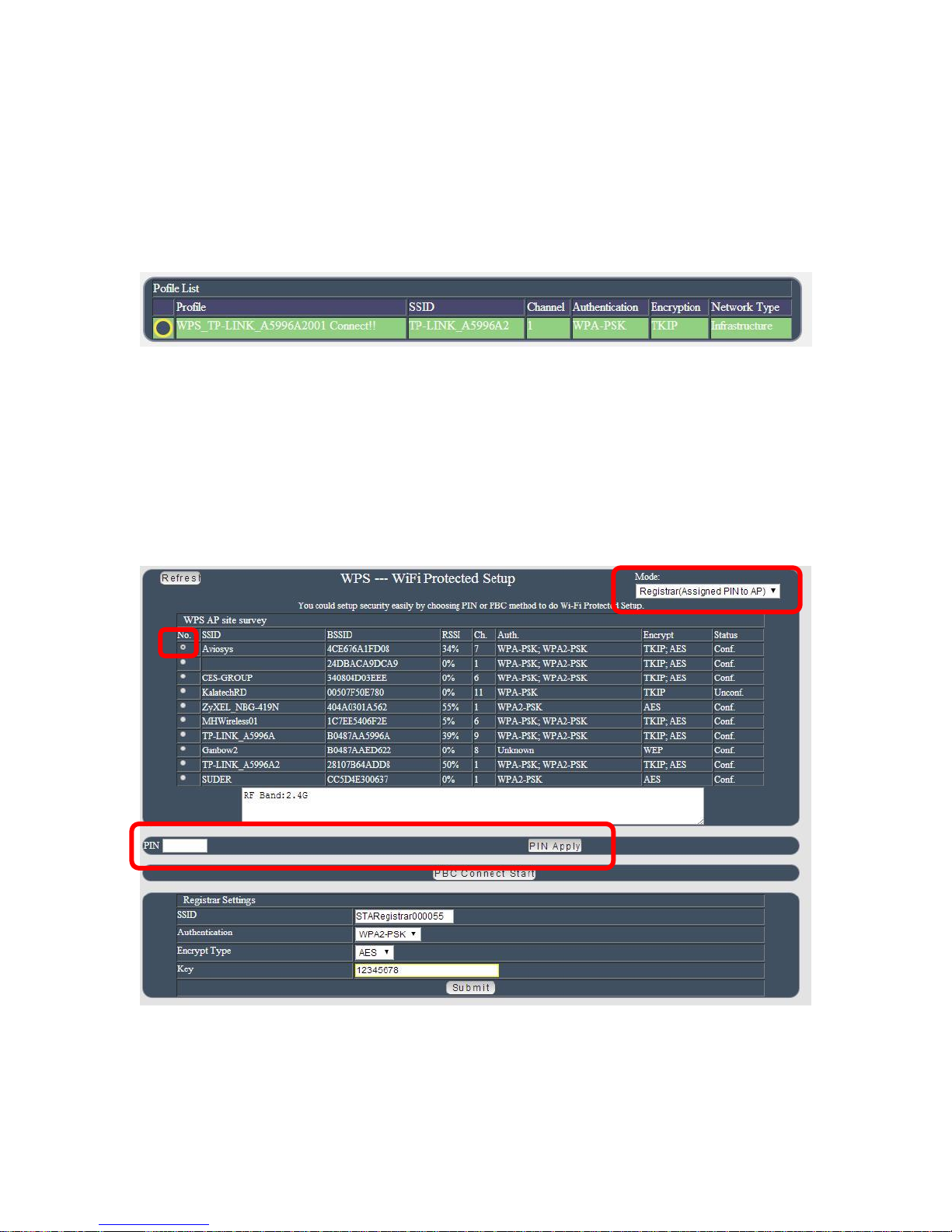
-By Registrar
Step 1 : Select the router user want to connect .
Step 2 : Select “Registrar “ and Type the PIN number supply by user WiFi AP ( Router )
into Pin area and then press button “Pin Start “ then user will see “Configured “ in WPS status
as connect successfully.
Step 3: User can see the WPS connection in section “ WiFi Info “ & “ WiFi Survey “ of Network
- 57 -
Page 58
Application Settings
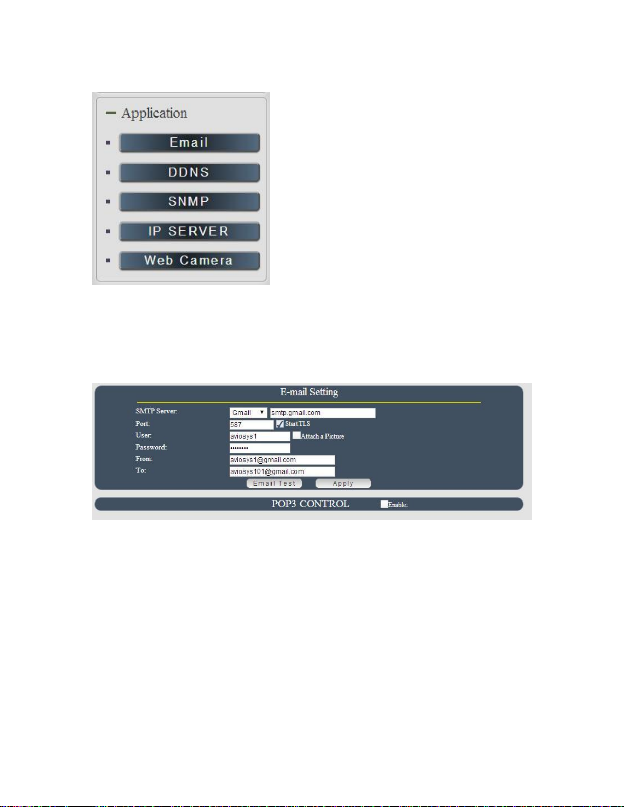
Email
In email section , there is 3 function :
- Receive Email with Current & Temperature info. as 9258W2 device boot up.
- Email alarm as over setting at Current and temperature.
Notice : To send out the email successfully , please double check the setting of user DNS .
(Network DNS setting)
A. Receive Email with IP, Current information as 9258W2 device boot up.
- 58 -
Page 59
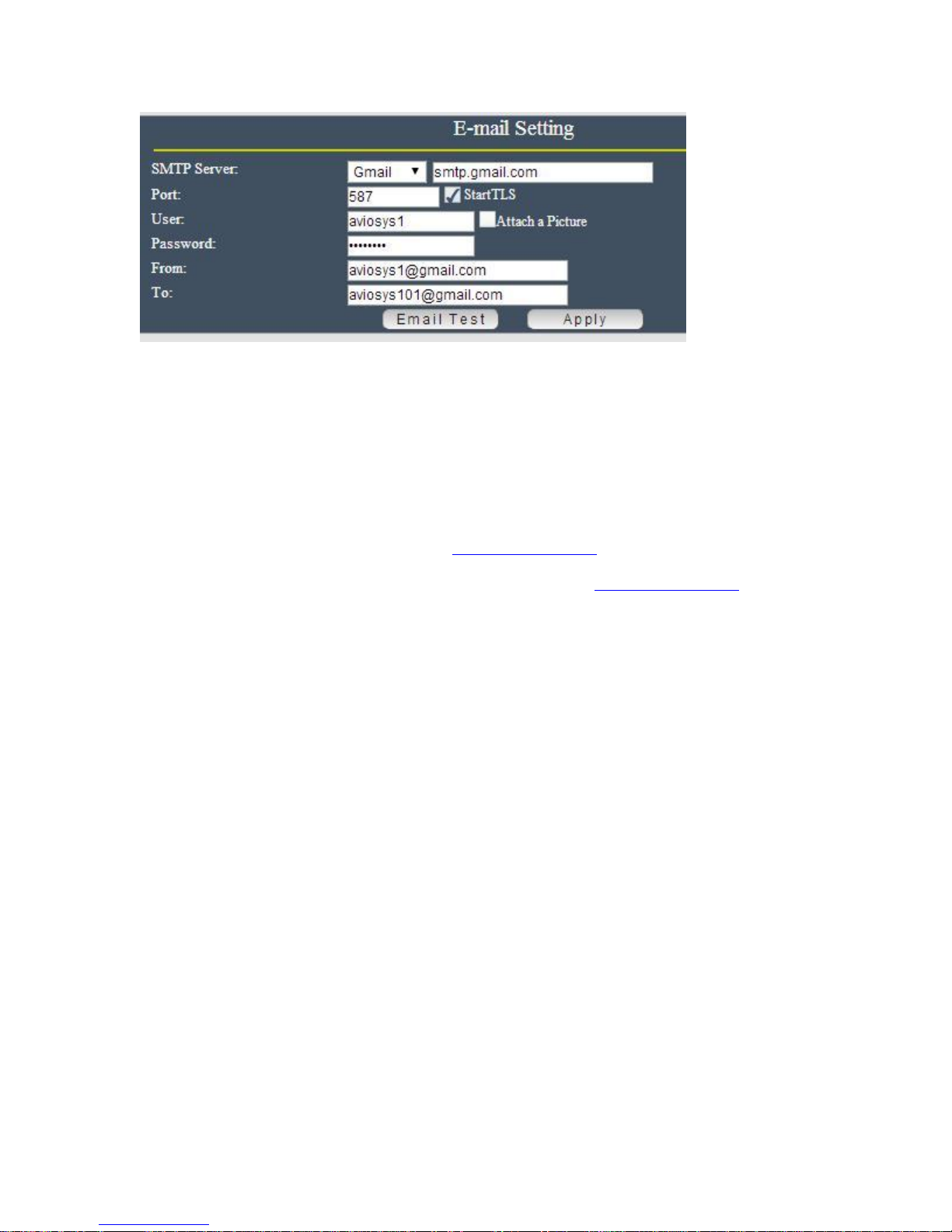
The 9258W2 allows user to send from @gmail or @hotmail or @yahoo.com account .
SMTP Server: This is the mail server of sender .
If user select @gmail or @hotmail account as SMTP Server , 9258W2 will fill the SSL & Port
automatically
Port : This is the port of SMTP Server. Most common port to send out e-mail is port 25
User : Login for the e-mail address . Ex: [email protected]
Password: Password for the e-mail address. EX : 12345678
From : Mail sender address to send the E-Mail out . Ex: [email protected]
To : Mail receiver address to get the E-Mail in Ex: [email protected]
Email test : Can help to check if the email setting work.
Apply : To save the setting in this section .
B. Email alarm as over setting at Current and temperature.
To get the email advice as over setting value of Current and Temperature , please do setup the
email information in “Email setting “ above and also the limit setting in “ Advance setup” of
“Control “ page of “ IO Control” section .
1st Setup the email setting for sender and receiver account .
Note : To send out the e-mail successfully ,the correct DNS information for setting up is
necessary . Please check user Router or check with user ISP company.
n d
2
Enable the email alarm function in “ Advance setup” of “Control “ page of “ IO Control”
section . Please refer page 32.
- 59 -
Page 60
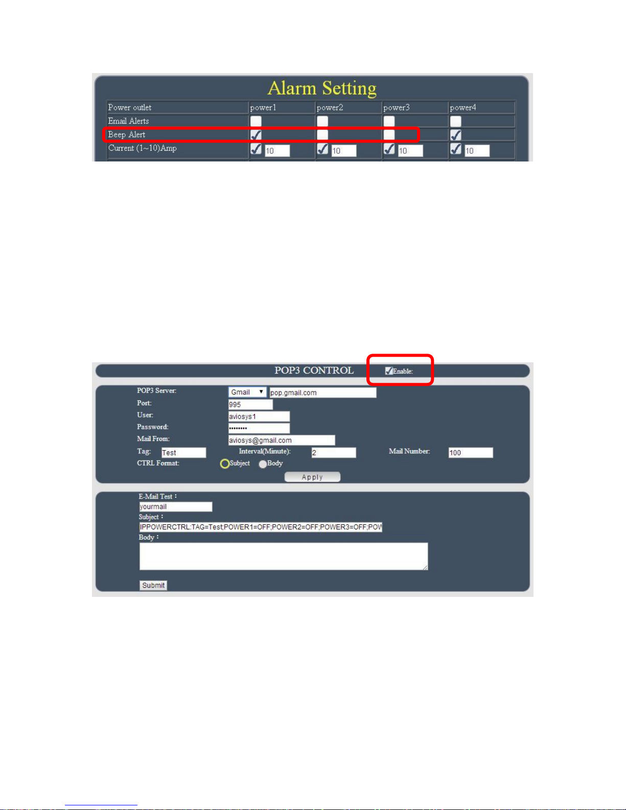
3rd Setup the limit range of each port. And click “Apply” to save the settings.
C. POP3 Control
User can control each port turn ON or turn OFF by email. The command format is limit .
Please enable the function first .
Settings section :
To setup 9258W2 get controlled by email , user need to know the sender`s email address and
receiver`s email account name and password.
- 60 -
Page 61
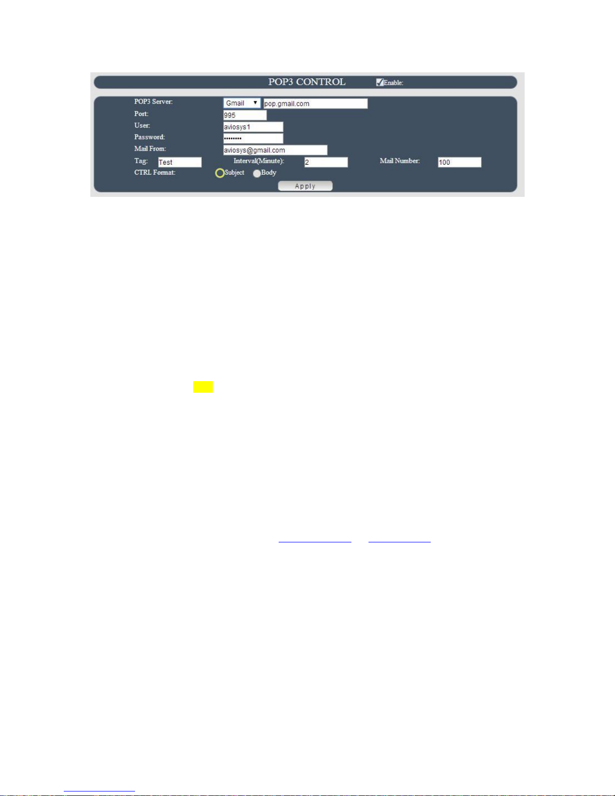
POP3 Server: This is the mail server of receiver .
Port : This is the port of POP3 Server.
If user select @gmail or @hotmail account as SMTP Server , 9258W2 will fill the SSL & Port
automatically.
User : The username to login the receiver`s e-mail Ex: aviosys1 or [email protected]
Password: Password for the e-mail address. EX : 12345678
Mail From : sender`s email address . Ex: [email protected]
Tag : User can use any message for 9258W2 to recognize this mail as 9258W2 command
mail .
EX:
As type “ Test “ in TAG area, the command contents is as following:
IPPOWERCTRL:TAG=Test;POWER1=OFF;POWER2=OFF;POWER3=OFF;POWER4=OFF
Interval (minutes) : The time between send and receive the command email.
Mail Number : For 9258W2 to search as command mail in the number of your email
receiver latest . EX : setup 20 that 9258W2 will check the latest 20pcs email in receivers
mail box for the 9258W2 command mail
CTRL format : Control format by subject or by body ( email contents)
For example : Use Gmail as sender and receiver
Sender`s email : [email protected]
The username to log in sender`s gmail : [email protected] or [email protected]
The password to login sender`s gmail : 12345678
Command format & Example :
User can get the email command contents in the section . And execute a email as press “Submit
“ if user had email setting the PC as following :
- 61 -
Page 62
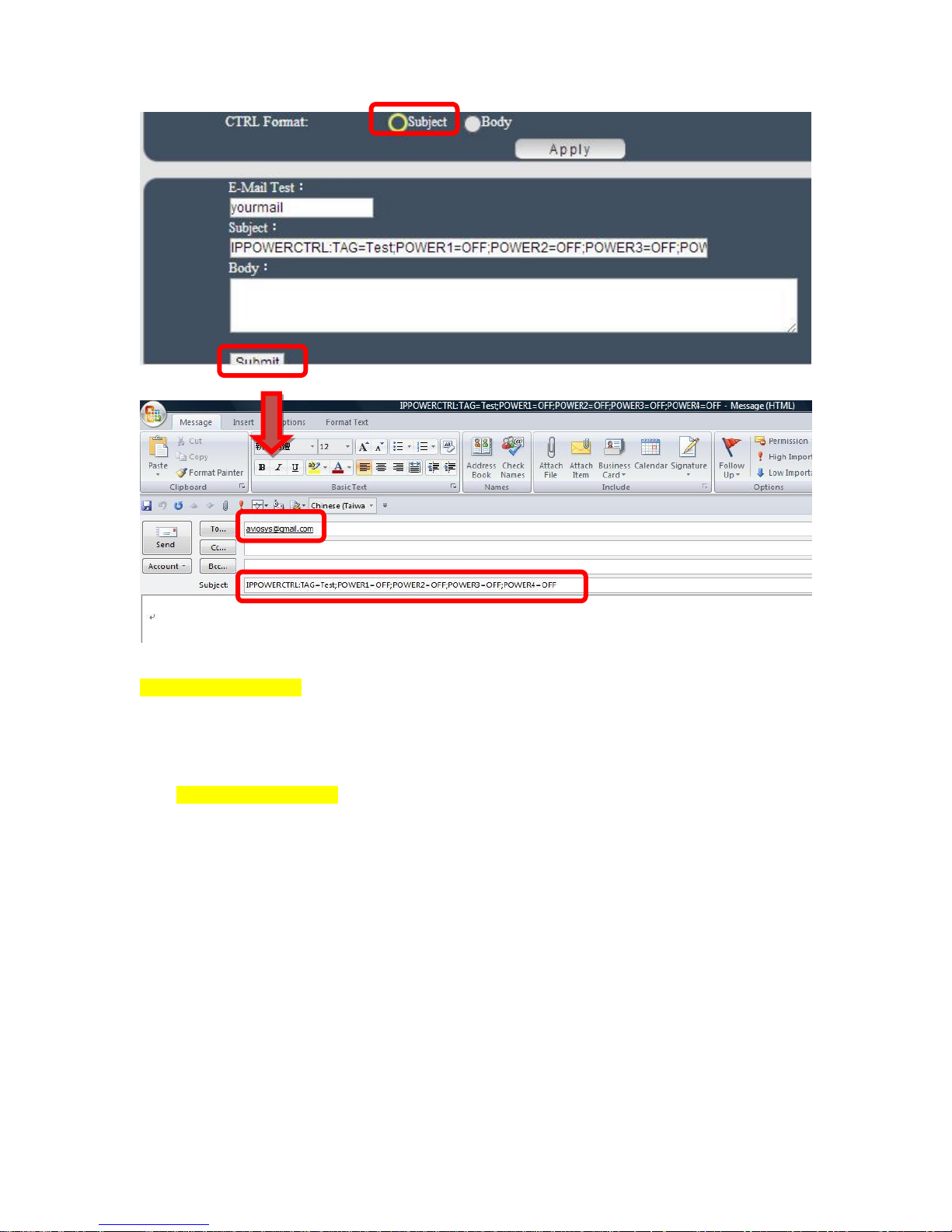
Command format :
IPPOWERCTRL:TAG=Test;POWER1=OFF;POWER2=OFF;POWER3=OFF;POWER4=OFF
There are 2 section of the command
1. IPPOWERCTRL:TAG=Test
This is command part. Beside the tag message part ( like Test on above example) user can
change in setting section , the other command must be CAPITAL and are fixed content .
2. ;POWER1=OFF;POWER2=OFF;POWER3=OFF;POWER4=OFF
This is to set the outlet number ( POWER1= ) and action ( ON/OFF) , user can only control 1~4
port ON/OFF by email. Please Each outlet command
EX: Put “ 14ON” in tag section and place the command as following : ( at subject or body
depends one users setting) :
IPPOWERCTRL:TAG=14ON;POWER1=OFF;POWER4=ON
- 62 -
Page 63
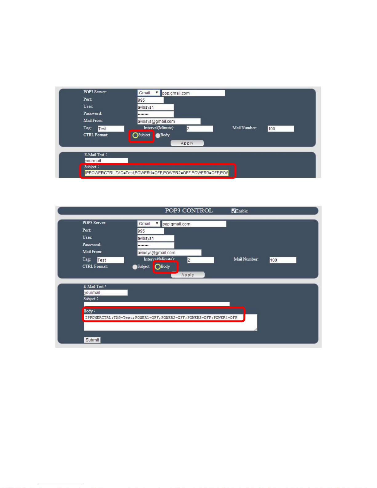
Email example :
Execute email command by “ Subject “
Execute email command by “ Body “
- 63 -
Page 64
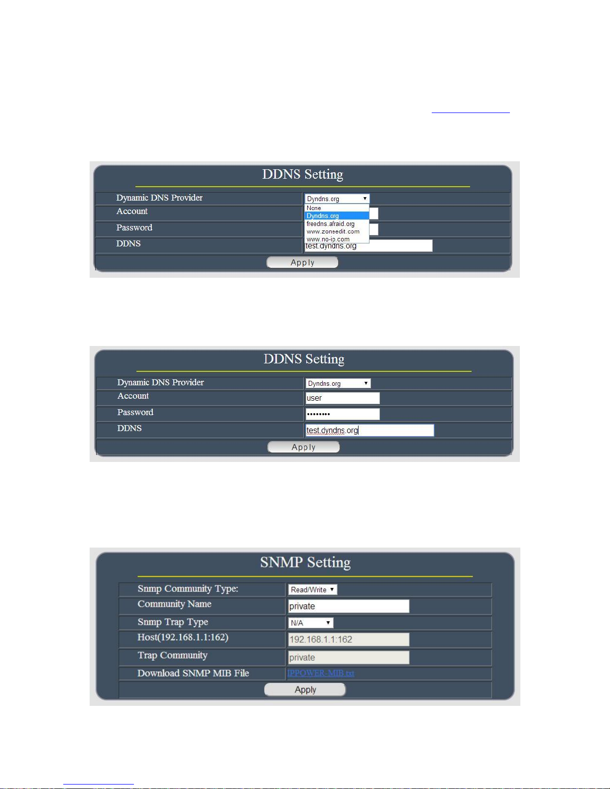
DDNS
The DDNS section allows user to setup the 9258W2 with a DDNS server (i.e. www.dyndns.com).
After the server has been setup correctly, enter the necessary information into the 9258W2
DDNS settings. Note : The DNS server will have extra change as apply new
account.
Account : the username /account name of DDNS account
Password : the password of DDNS account
DDNS : The DDNS name user apply . Ex: abc.dyndns.org
For Example :
SNMP
This section is for development of system integrator who familiar with SNMP knowledge.
- 64 -
Page 65
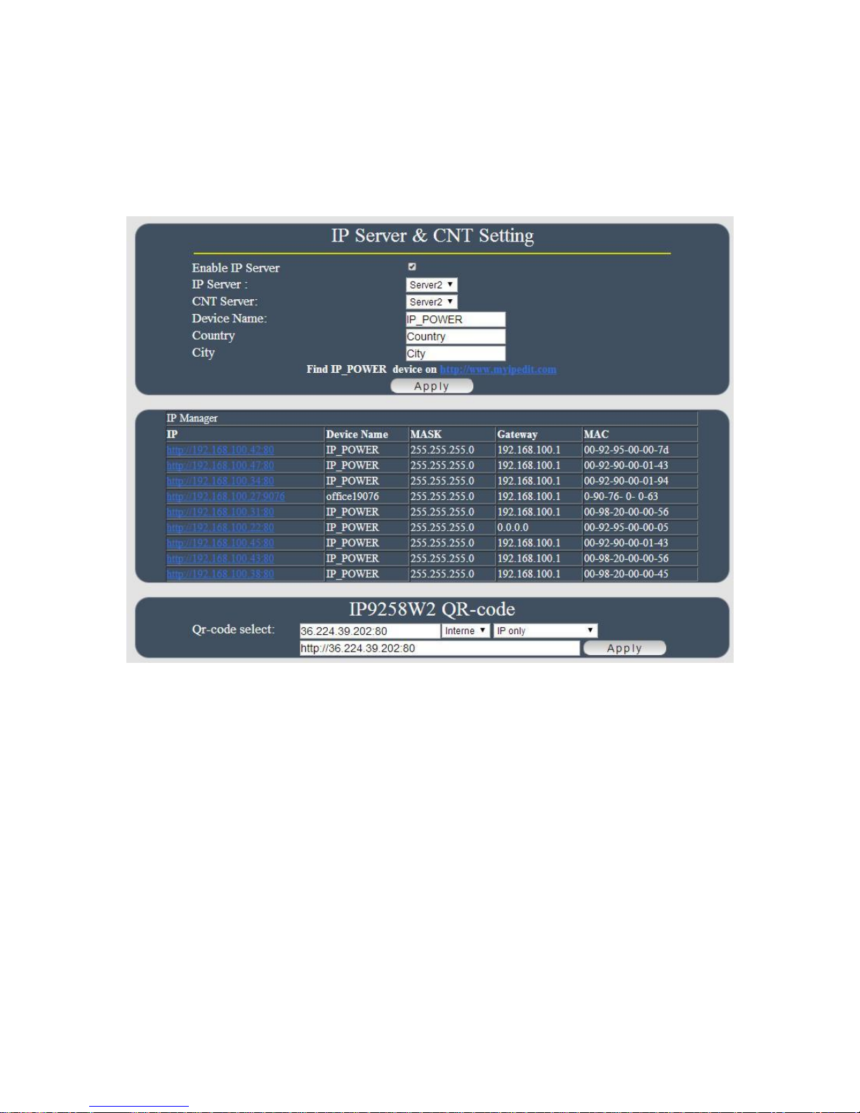
IP SERVER
In this section , use can setup
A. IP Server & CNT ( Cross Network Technology ) ,
B. IP Manager : Search other IP Power device in the same LAN of 9258W2 .
C. Get the QR code of 9258W2`s IP address.
IP Server & CNT Setting :
The IP SERVER allow 9258W2 to be easily accessed on the internet by our IP Power Center or
IP EDIT. With this feature anyone can find there device with no problems.
IP Server: Allows user can find user 9258W2 on the internet without having to remember long IP
Addresses. Instead user can just remember the name of user device.
Enable IP Server : Enable or disable this function chuck .
IP Server & CNT Server : For easily setting , Please select same server number for the 2
part.
User can search the 9258W2 by Device name , Country or City.
This allows the device to easily be accessed on the internet, user no longer have to port forward
user device to be able to use it. Only some devices are CNT compatible.
- 65 -
Page 66
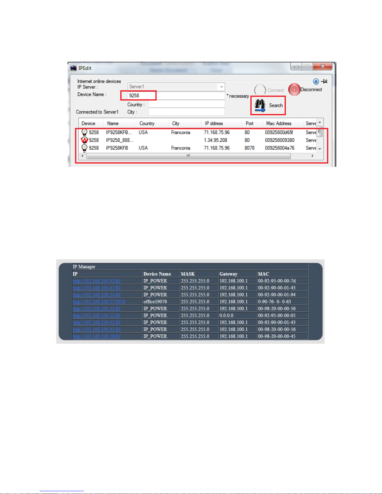
Please refer page #24 for the function of IP Server
IP Manager :
User can directly search other IP Power device in local network (LAN) here .
- 66 -
Page 67
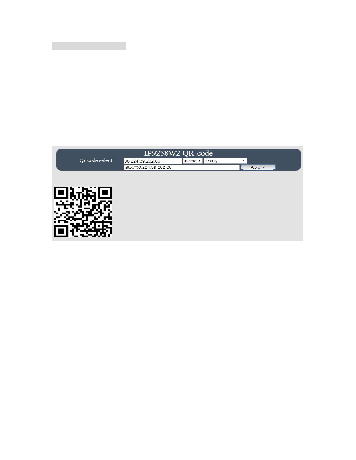
QR code of 9258W2 :
User can create own QR code of the IP information of 9258W2 ( LAN / WIFI / Internet), and
scan / record in user QR code APP for quick search or log in 9258W2 .
Please make sure to do port forwarding ( local port and forwarding port must be same
port ) if need to get the QR code which can directly go to the webpage of 9258W2 on
Internet
QR Code in 9258W2 webpage
This QR code help user to get in the webpage IP address 9258W2 by smart phone quickly.
There is history in QR code app for user to check 9258W2 IP soon .
- To view the 9258W2 webpage on Internet , please do “ port forwarding “ first in router.
- To view the 9258W2 webpage on LAN , please make sure user smart phone is under
same segment ( refer Page#20 , user will need to make sure that the first 3 segments
of user 9258W2 IP Address must match the first 3 segments of user gateway IP. )
Please select the QR code of IP Information from Internet, LAN, WAN & IP Server.
And then press “Apply to create new QR code.
# Internet: It will create QR code with the Internet IP of the environment of 9258W2 .
( need port forwarding ) .
# WAN / LAN: It will create QR code with the WAN/LAN IP of 9258W2 .
# IP Server : Please enable “IP Server function first and then it will create QR code with the
MAC for user to use IP Server ( of IP EDIT ) in user smart phone .
QR Code in IP Server :
Before get the QR code in IP Server , please make sure the IP Service is enable in 9258W2
webpage.
IP Server : With our own CNT function , user can easily get the Internet IP by IPEDIT
- 67 -
Page 68
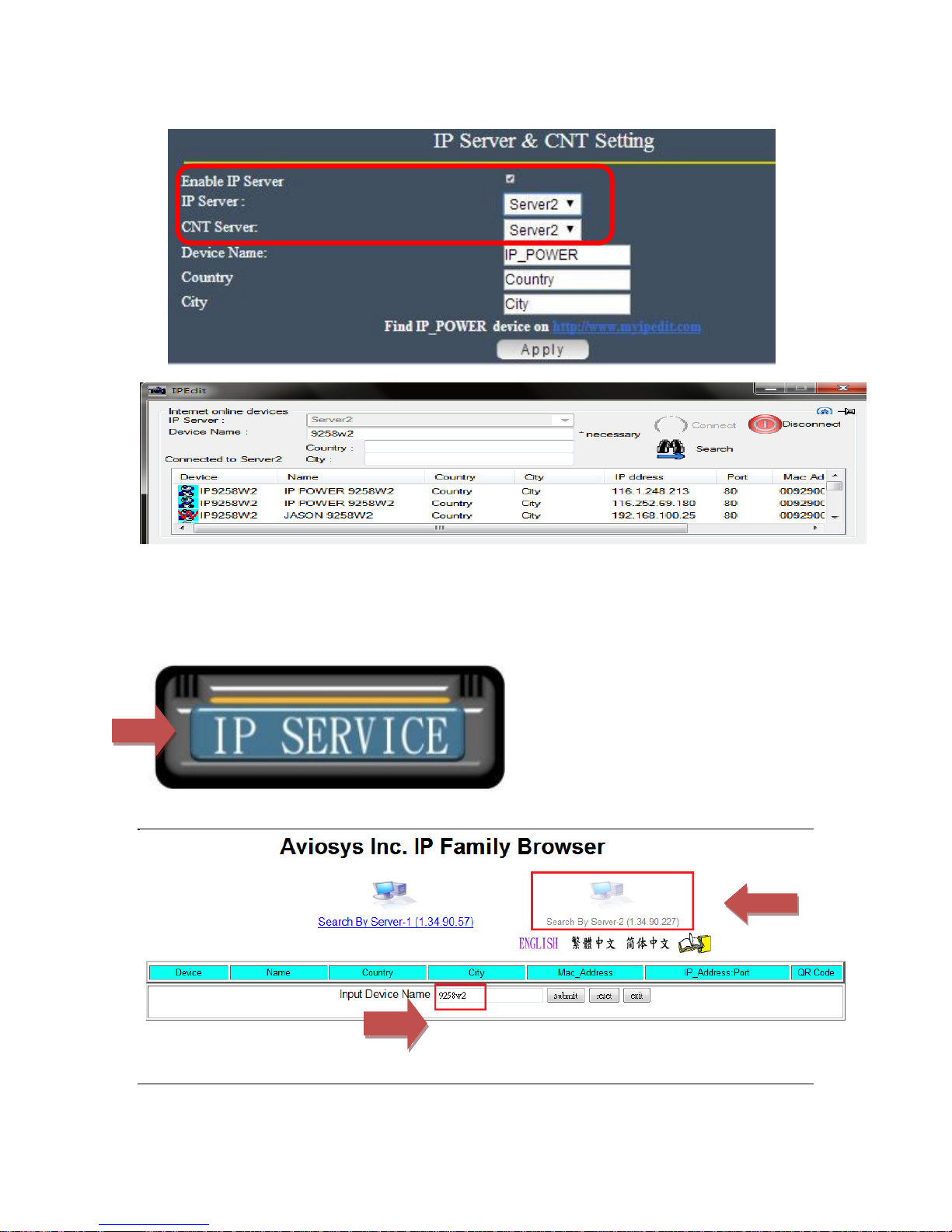
Please go to our online IPEDIT : www.myipedit.com
Them please select “ Server 2 “ and type the device name ( if change) or 9258W2.
- 68 -
Page 69
USB WebCam
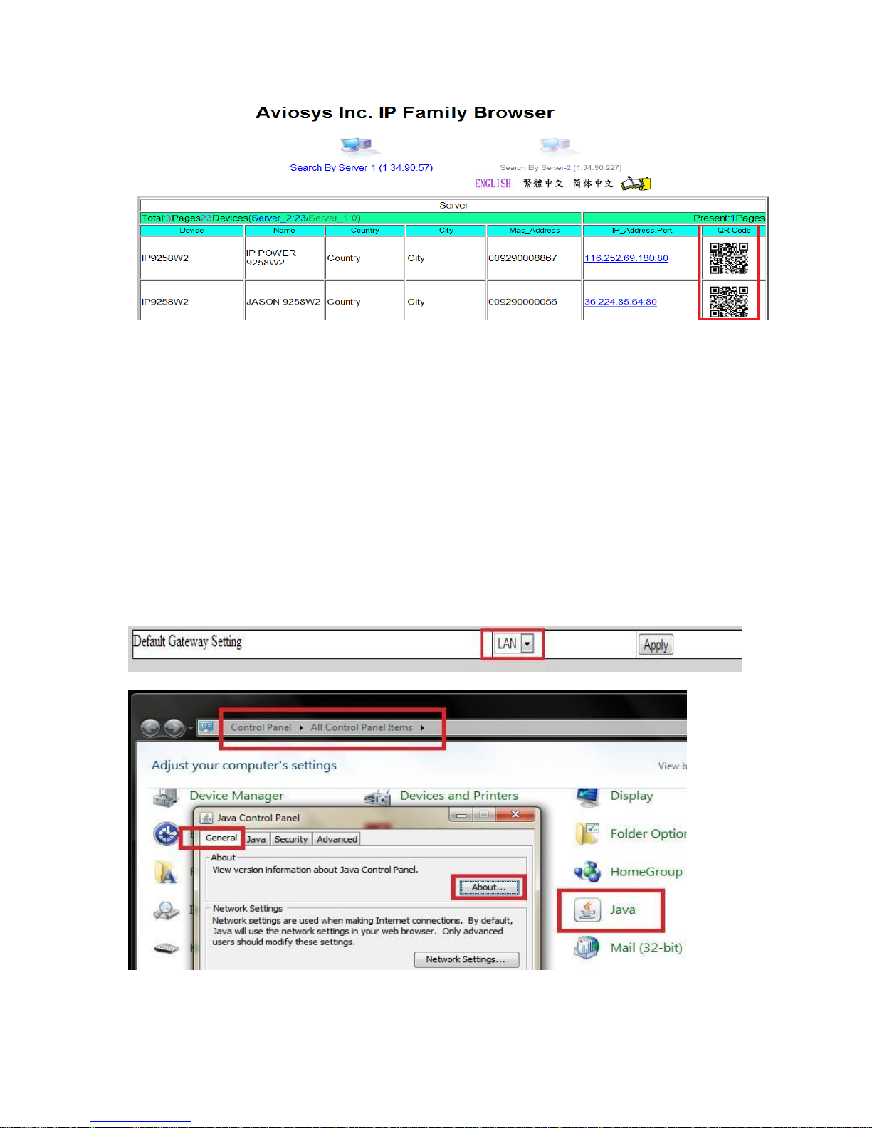
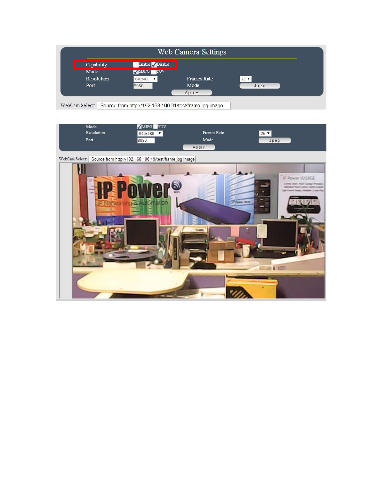
This section allow user to connect USB Webcam ( with UPNP function , M-JPG / YUV format )
and view the webcam in 9258W2 webpage directly. To work with 9258W2, the USB Webcam
need to support UPNP and video as M-JPEG or YUV format to view the area near 9258W2.
Note : The JAVA version should be 1.60 or above for USB Webcam view under web browser
Internet Explorer -IE and the gateway setting must be correct - WAN or LAN as port forwarding
and view on Internet
- 69 -
Page 70
- 70 -
Page 71
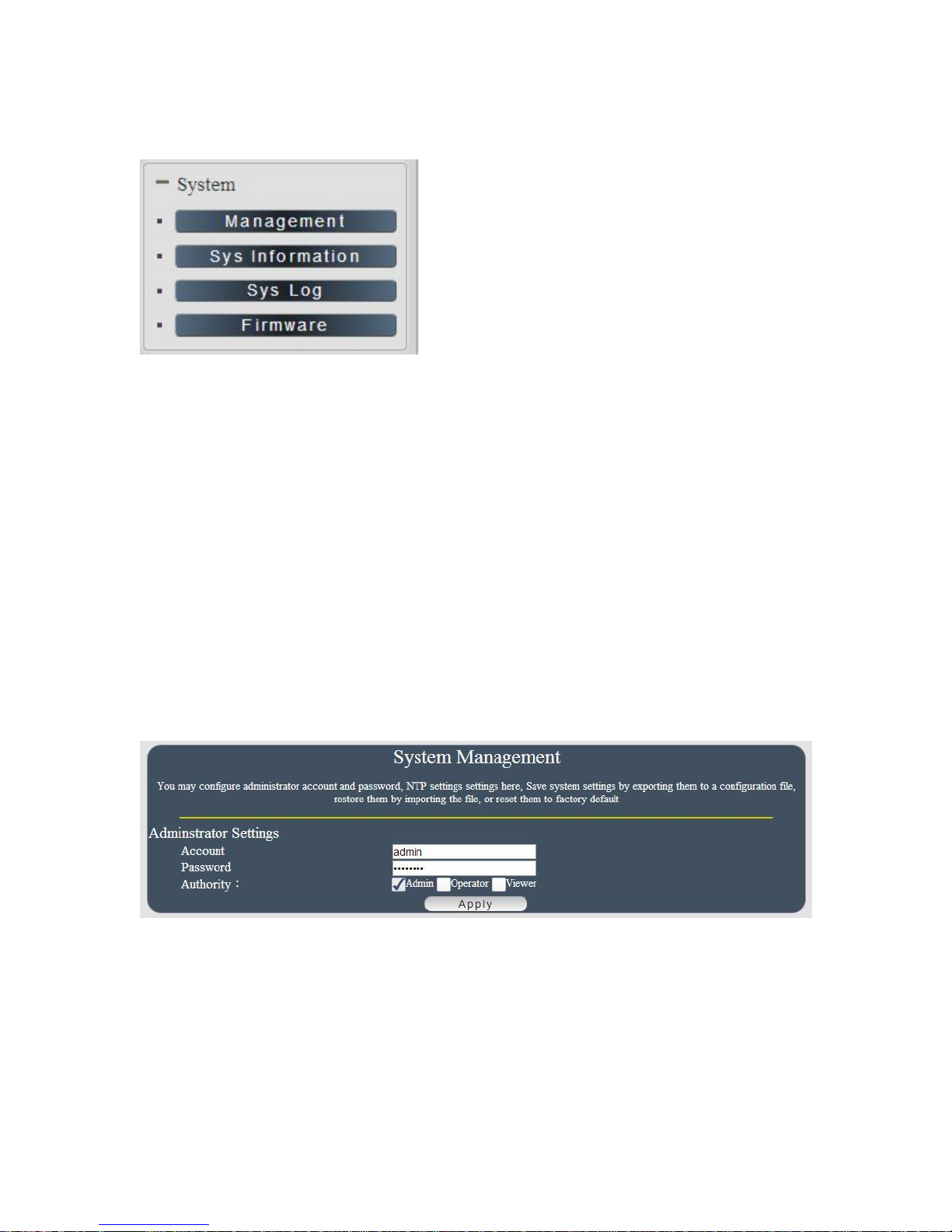
System Setting
Management
In this section there are several setting :
Administrator setting, Host Connection Interval , NTP setting ,Export Setting , Import Setting ,
Load Factory Default , Restart System
The message show :
“ You may configure administrator account and password, NTP settings here, Save system
settings by exporting them to a configuration file, restore them by importing the file” or reset
them to factory default
Administrator setting
The User Management section allows user to create users that will be able to access user device.
There are two main types of users:
There are three Authorities in 9258W2. The account name and password can be changed by
user but each Authorities only support one Account name & one password.
Administrator: The Administrator has the authority to create other users, remove users, and
control the device. 9258W2 will asked to log in again as change the default setting here.
Operator : The operator can only control the setting of “ IO Control “ section but can not see
other page of 9258W2 .
Viewer: The viewer can only see the “ IO Control “ section but can not see other page of 9258W2.
- 71 -
Page 72
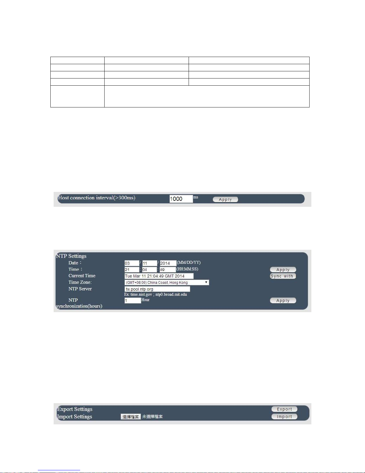
Default Setting of the authorities :
Authority
Account name
Password
Admin
Admin
12345678
Operator
user
user
Viewer
guest
guest
Note
Please amend the password as number or English character from
1 to 8 characters.
Do not use special symbol like “ ” ; : ~ ! @ # $ % ^ & * ( )
Please click “Apply “ button after change the account name / password
Host Connection Interval
The setting is for user to control the 9258W2 response time for IO sensor like ????? the time of
speedy , timeline update . Default 1000ms ( = 1 second)
The higher you set up the range , the response time will be slower
NTP setting
In this section , user can setup the date , time and NTP server to get the time synchronization .
NTP synchronization : User can setup the time gap ( 1~300 hours ) for 9258W2 to check the
time with the NET server .
Export Setting
User can export the setting of 9258W2 into a “ DAT “ format .
It will save most the setting in 9258W2 .
- 72 -
Page 73
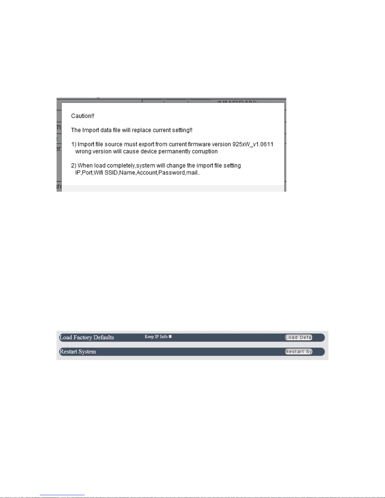
Import Setting
User can import the file which was exported from 9258W2 as “ DAT “ format .
It will help user to setup many 9258W2 device in a short time.
As press “ Import “, there is caution message show as following :
Before click ok to import please do read following notice :
Do NOT import DAT file which is not export form 9258W2. It is out of warranty support if any
damage by import .
Please do import the file in LAN / Ethernet . To avoid import fail , please do not import file by
Internet
Load Factory Default & Restart System
In this 2 section , user can click one button to set back the setting to default or restart the
9258W2 without device nearby user side.
Note : The factory default setting of 9258W2 IP is assigned by DHCP. It will change the IP
if load factory defaults .
- 73 -
Page 74
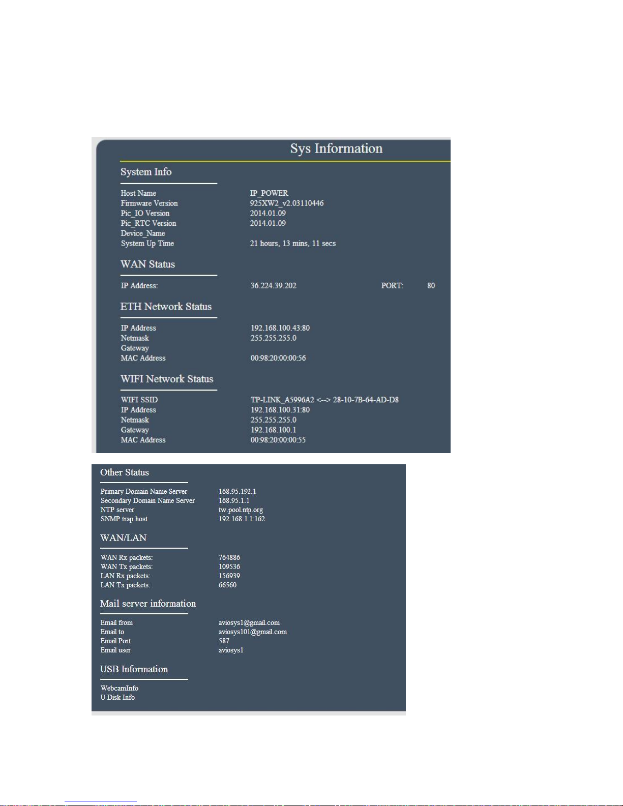
System Information
In this section , user can get the system information :
- 74 -
Page 75
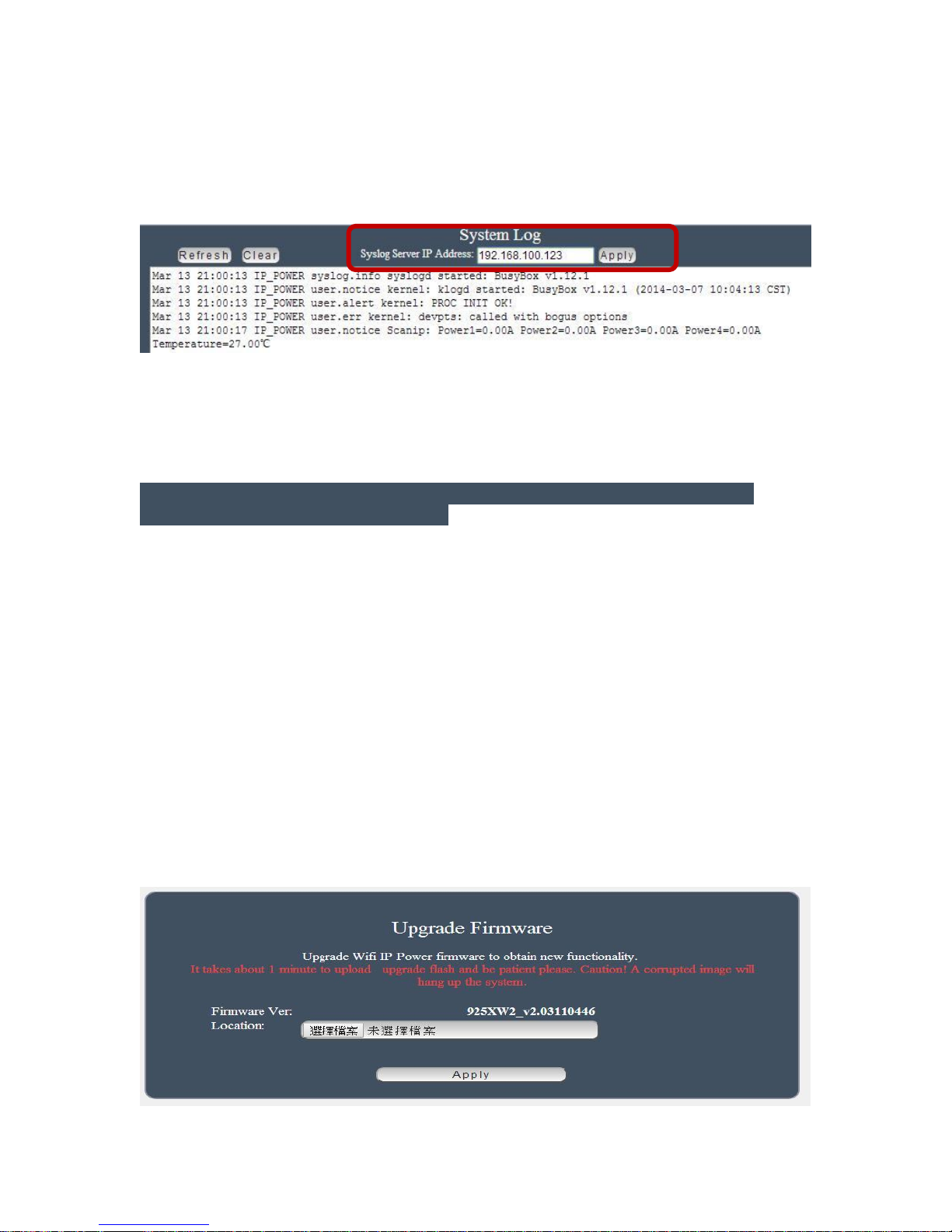
System Log
In this section , user can get the 9258W2 system operation information and send the information
to assign Server IP address ( not support name ) . The system information will be deleted
after 9258W2 device power reboot.
Please click the IP and save by click “ Apply”
Firmware
The firmware update function only support in LAN connection . NOT support under WiFi
connection . Before update , please DO READ THE MESSAGE BLOW :
It takes about 1 minute to upload upgrade flash and be patient please. Caution! A
corrupted image will hang up the system.
To update the 9258W2 , please follow the instruction below to prevent anything happens like
update incomplete or hardware disable which may be caused by wrongdoing of updating :
1) Turn off all chat programs including ( Skype, FB. QQ, AIM, Yahoo messenger ….etc.)
2) Check to make sure that all devices are turned on safely and powered
3) While updating do not turn off the power
4) Make sure that the cable is connected firmly
5) Do not interrupt the update process, the update must be completely finished .
6) Turn off, any Spyware or antivirus software which may conflict with the update.
7) Update firmware in the Local Area Network (LAN)
8) Support update under 32bit Web Browser ( 32 bit version only ) like IE, Google Chrome,
Firefox . DO not use browser at 64 bit version
9) Please change the PORT as 80
10) REBOOT and DO the Hardware RESET ( keep pressing RESET button for 10secs ) after
update successfully.
11) Clear the COOKIES to avoid get the old webpage .
Please also update the notice in webpage before update :
- 75 -
Page 76

Controlling the Device
By IR Remote Controller
To control 9258W2 by IR remote power controller we supplied, please use 5 buttons in this
remote controller : Power button , button #1~# 4
Enable remote controller : Press Power button one time and 9258W2 will response a short
beep which mean the remote control function enable .
Disable remote controller : After enable the function , then pres Power button one time
again , then 9258W2 will response 2 short beep which mean the remote control function
disable.
Outlet ON/OFF control : Press the Button #1 ~#4 to turn output 1~ 4 ON / OFF .
- 76 -
Page 77

CGI HTTP Commands
CGI Commands allow you to easily integrate the 9258W2 with other systems and programs.
Please read the instructions carefully on how to use the Http:// Commands
To use http:// Commands open up a web browser and type in the command that you would like to
use.
1. User authorization .There are 3 formats :
For example : IP address 192.168.1.18 ,Username : admin. Password : 12345678
1.1 http://admin:[email protected]/set.cmd?cmd=getpower
1.2 http://192.168.1.18/set.cmd?user=admin+pass=12345678+cmd=getpower
The above 2 way also for HTTPS
2. Command
set.cmd?cmd=
All command do not separate capital / lower case , the connect symble between
commands can be “+” ,“&” and “?”.
2.1 To get firmware version : getversion
http://192.168.1.18/set.cmd?cmd=getversion
System return :
CGI Command : Data follows
Version=9258W_N_v1.0.0.1
2.2 To get MACaddress:getmac
http://192.168.1.18/set.cmd?cmd=getmac
System return:
CGI Command : Data follows
mac=00929000008F
2.3 To get the status of power on/ off: getpower
http://192.168.1.18/set.cmd?cmd=getpower
System return:
CGI Command : Data follows
p61=0, p62=0, p63=0, p64=0
P61 to P64 means : POWER1 to POWER4
2.4 To get Current : getcurrent
http://192.168.1.18/set.cmd?cmd=getcurrent
- 77 -
Page 78

System return:
CGI Command : Data follows
c61=0.000000, c62=0.000000, c63=0.000000, c64=0.000000, temp=22.700001
C61 to C64 means 4 currents ,temp is temperature (as Celsius )
2.5 To get temperature (Celsius): gettemp
http://192.168.1.150/set.cmd?cmd=gettemp
System return:
CGI Command : Data follows
temperature=22.700001
2.6 To set the power on / off :setpower&p6x=0 or 1
p6x=0 means off,p6x=1means ON,x can be 1 to 4 ( power1 to power 4)
Example : Turn on POWER1 and POWER2 and turn off POWER3:
http://192.168.1.18/set.cmd?cmd=setpower&p61=1&p62=1&p63=0
System return:
CGI Command : Data follows
p61=1,p62=1,p63=0
2.7 Setup power to reboot as RESET:setpowercycle& p6x=delayTime
X can be 1to 4 ( power 1 to power 4 ) ,;dealyTime mean the time ( second) waiting
for reset
For example :
http://192.168.1.18/set.cmd?cmd=setpowercycle &p61=5&p62=2&p63=4
System return:
CGI Command : Data follows
p61 cycle ok,p62 cycle ok,p63 cycle ok
- 78 -
Page 79
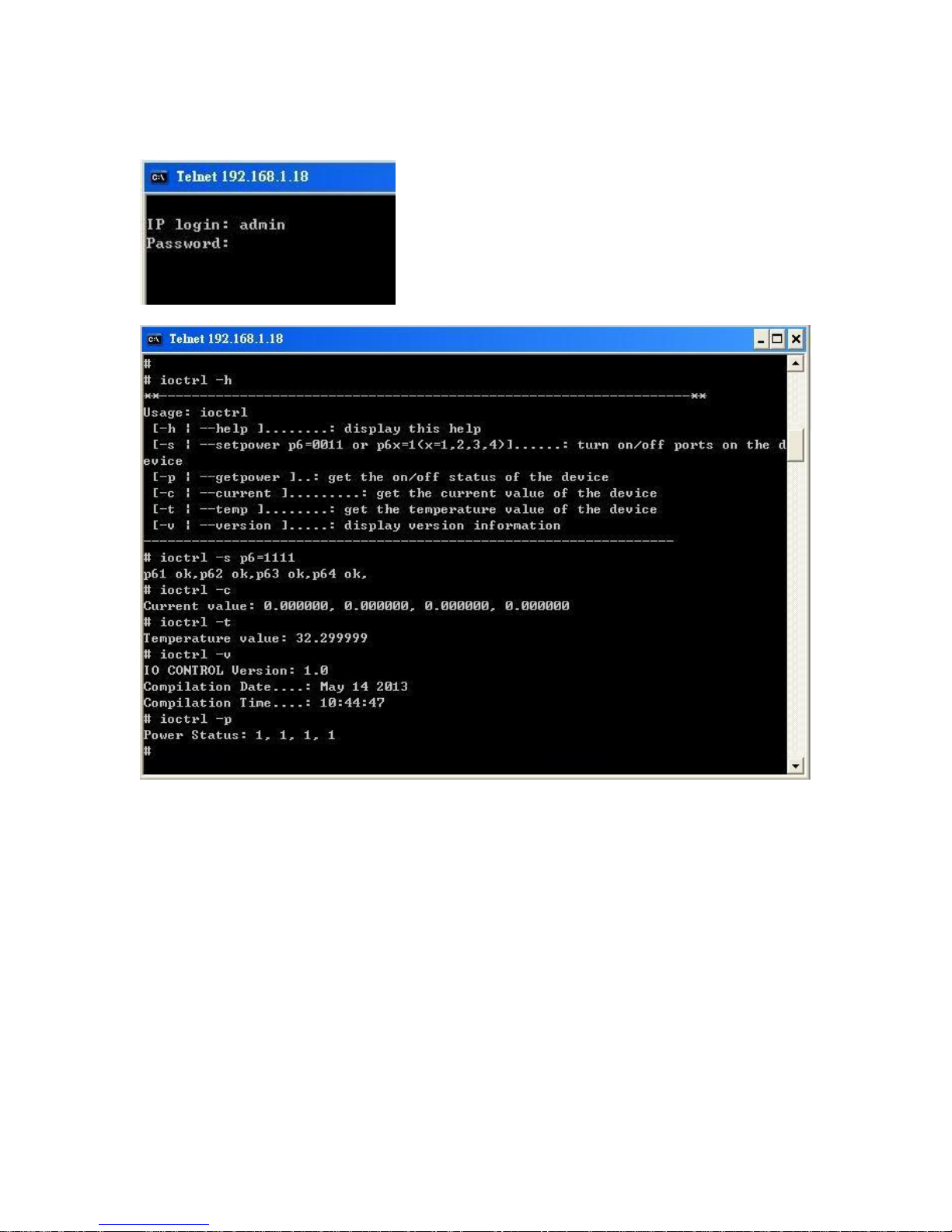
Telnet Control
Serial Com (RS-232) Control
For internal debug purpose only .
- 79 -
Page 80

FAQ :
Q1: Why can I see 2 IP address on IPEDIT.exe but can only reach one ?
Why did IPEIDT.exe show the LAN IP address as no network cable connect ?
Why did IPEDIT.exe show the WIFI IP address as no WIFI router available ?
A1: 9258W2 will remember the LAN / WAN setting one connect .Please select the IP you can
log into 9258W2 to operate.
There is no problem if connect both LAN and WAN
But the Gateway setting will affect as working on Internet and also sending / receiving
email . User should select the correct Gateway as need to get into 9258W2 on Internet
Q2 : Why can`t I see my 9258W2 after arrange the port forwarding in my router?
A2 : Please make sure the Gateway is correct Gateway ( LAN or WAN )
Q3 : Why can`t I receive email ?
A3: Please check the setting first and then make sure the DNS is correct ( Check your router /
asked your ISP company ) .There is test button for checking the the setting success or fail to
send mail.
Q4 : Why can`t I see the current chart ?
A4 : Please check the web browser version . Need IE 9.0 or above version
To see this section display normally, please do use IE9.0 or above, Firefox,
Google Chrome or Safari and set resolution at 1280*768 .
Q5: Why can`t I get the IP in IPEDIT by LAN after delete WIFI profile or lost WIFI AP
connection ?
A5: If the WiFi connection for 9258W2 lost or the WiFi AP router damage,
9258W2 can not get the WiFi IP then it will change it`s IP to fixed IP address as 192.168.1.168 .
User can not see the IP by IPEDIT as the Gateway is still at EiFi .
At this time , there are 2 ways re-log in 9258W2 . :
BY WiFi connection : Please reboot 9258W and Re-connect 9258W2 with new WiFi router by
“ WPS “ button ( can do this way without 9258 W2 power reboot )
BY LAN connection :
Please refer following step :
- 80 -
Page 81
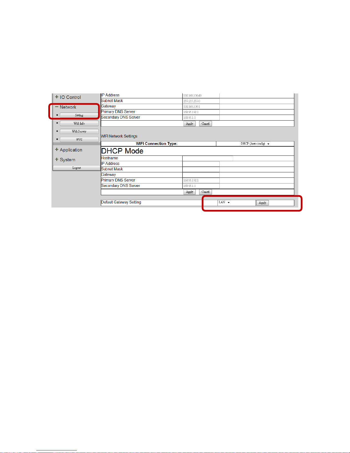
Step1: Please connect 9258W2 to your PC directly and change the IP address of your PC as
192.168.1.xxx ( set the IP of your PC to be the same segment of 9258W2 . )
xxx can be 1~255 but not 168 .
Step 2 : After log in to the 9258W2 in LAN, please go to
Network Setting Default gateway setting to change the Gateway from “ WiFi ” to “ LAN
“ and click “Apply” .
Step 3 : Connect your PC and 9258W2 to a router by LAN. Then reboot 9258W2 (MUST DO) .
After 45 seconds with a long beep, you can found the LAN IP of 9258W2 by IPEIDT.exe
Q6: How can I reset to default:
A6 : Please use tiny pin head and keep pressing the button “RESET for 5 seconds at least and
release , there is a long beep sound after around 45 seconds . Then please power reboot the
9258W2 . after around 45 seconds there is a middle beep sound then you can use IPEDIT to
hekc
which means system reboot successfully and set back to default.
Q7 : Why can`t I see the video of USB Webcam in 9258W2 webpage ?
A7 :
Please check the following premises :
Please make sure the setting of “Capability “ is “Enable “
- The USB WebCam support UPNP connection and support M-JPG or YUV format .
- The web browser is IE 9.0 at lest or above .
- The JAVA version is 1.60 or above
- The gateway setting is correct - WAN or LAN to view on Internet
- 81 -
 Loading...