


User Manual
16/24 Ports Managed
PoE Ethernet Switch

Preface
Th e u se r m an ua l m ai nl y i nt ro du ce s t he pr od uc t s ha pe , p ro du ct
po si tioning, hardw ar e i ns ta ll at ion, Web mana ge me nt an d o th er
re la ted informati on .
(2) V ari o us Si g ns
Imp rope r opera tion m ay dam age th e devi ce or cau se dat a loss .
Sup plem ental i nstr ucti on for o perat ion co nten ts.
Format
Description
< >
[ ]
/
Illustration
(1) F orm a t of Gr a phi c s Int e rfa c e
“<>”me ans bu tton n ame, su ch as “cli ck <Co nfir m> but ton”.
“[ ]”mea ns win dow na me, me nu name a nd dat a tabl e, suc h as“pop o ut [New
use r] win dow”.
“/”is us ed to se pera te Mult i-le vel me nu. Su ch as [f ile/n ew/f olde r] mult i-le vel
men u [fil e] men u [new] sub-m enu [f older ] menu o ptio n.
Cau tion
Ins truct ion

Content
1
Product Introduction
1
1 1. Overview
1
1 2.
Board Diagram
1 3.
1
Product Feature
3
2
Installation
4
2.1 Shipping List
2.2
Installation Precautions
4
2 2 1. . Safety Precautions
4
2 2 2. . Installation Requirements
5
2 3.
Installation Way
2 1.3. Rack Installation
2 2.3. Workbench Installation
2 3.3. Wall-hung Installation
3 Function Configuration Guide
3 1.
Computer Requirements
3 2. Set up Network Connection
3 2 1. . Set Static IP for the Management Computer
3 2 2. .
Confirm the Network Connection by Ping Command
12
3 2 3 . .
Cancel the Proxy Server
12
1 4.
Specification
1
2.2.3
The Requirements of Electromagnetic Environment
5
3 3.
Web Page Configuration Guide
13
3.3.1 Start and Login
13
3.3.2 Change Language
14
4
6
7
7
10
10
10
10
6
3.3.3 Common Buttons Introduction
15
3.3.4 The Default Configuration
15
3.3.5 Web Users Timeout
17
3.3.6 Backup System Configuration Information
17
3.3.7 Restoring the Configuration Information
17
4 3. VLAN Setting
20
4.3.1 VLAN Configuration
20
4.3.2
VLAN forwarding
22
4 4. Trunk Management
23
4.4.1
Trunk
23
4.4.2
RSTP
24
4 5. Port Security
28
4.5.1 Static Address Latch
28
4 6. Web Management
29
4.6.1 SNMP Setting
29
4.6.2
Email Alarm
30
4.7 Network Statistics
31
4.7.1 Network Statistics
31
4.7.2
MAC Address
32
4.8 System Management
33
4.8.1 IP Address
33
4.8.2
User Management
34
4.8.3 Log Information
35
4.8.4
File Management
36
4.9 PoE Management
37
4 Web Management
4 1. System Status
17
17
4.2 Port Configuration
18
2 4.
Cable Connection
2 1.4. Device Connection
2 2.4. Configuration Cable Connection
2 3.4. Power Cable Connection
9
9
9
9
3.3.8
Quit
17
1 2
1.3 Diagram Board
24 Po r ts Ma n age d E the r net S w itc h B oar d D ia g r am
1 Product Introduction
1 1 O. verview
Thi s item is a 1 6/24- port ma naged P oE Ethe rnet sw itch, w hich pr ovide s
16/ 24 *10 0Mb ps do wnl ink P oE Et her net p ort s, su ppo rts I EEE 802 .3 af /a t and
2*1 000Mp bs upli nk opti cal por ts and 2* 1000M pbs upl ink Eth ernet p orts.
It su pport s Layer 2 n etwor k manag ement a nd PoE ma nagem ent bas ed on web
and p rovid es high -spee d data fo rward ing. It i s widel y used in s ecuri ty
sur veill ance, n etwor k engin eerin g proje cts and s o on.
1.2 Product Feature
16/ 24 port s manag ed PoE Et herne t switc h provi des 16/ 24 10/ 100Mb ps
PoE E thern et port s and sup ports I EEE80 2.3af /at, 100 0Mbps
SFP p orts, 2 10 /10 0/1 000 Mbp s Eth ernet p orts;
24 po rts man aged Et herne t switc h provi des 24 1 0/100 Mbps RJ4 5
por ts, 1000 Mbp s SFP p orts, 10/ 100 /10 00M bps RJ4 5
por ts;
Pro vide we b-ba sed l aye r 2 net wor k man age men t and P oE ma nag eme nt
wit h simpl e opera tion pr ocess ;
Sup port hi gh-sp eed dat a forwa rding , perfe ctly de signe d for lar ge flow o f
vid eo data f orwar ding in s ecuri ty surv eilla nce;
Sup port on e-key r ecove ry of IP ad dre ss & us er pa ssw ord ;
;
Qui ck in sta lla tio n, eas y o per ati on and co nve nie nt for wall / d esk / r ack
ins talla tion.
*
dow nlink 2*
upl ink * upl ink
* dow nlink
2* upl ink 2* upl ink
Exc ellen t circu it isol ation p rotec tion, l ightn ing pro tecti on up to 2 KV
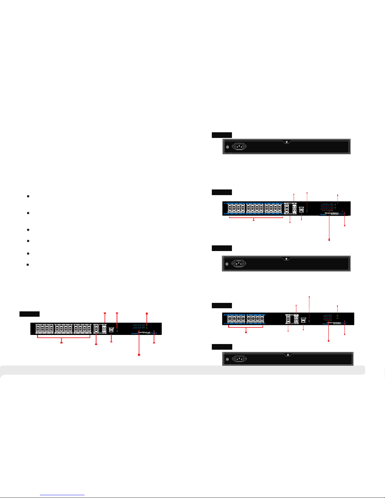
24 Po r ts Ma n age d P oE Et h ern e t Swi t ch Bo a rd D i a gr a m
Bac k panel
Fro nt pane l
Upl ink Gag abit
SFP P ort
Rec over IP
add ress
and
pas sword
Ind icate
10/ 100/1 000Mb ps
upl ink por t worki ng
sta tus
Con sole
por t
Upl ink Gig abit
RJ4 5 Port
Ind icate d ownli nk port
10/ 100Mb ps work ing sta tus
Ind icate p ower
sta tus
100 M
Eth ernet p ort
Upl ink Gig abit
SFP P ort
Rec over IP
add ress an d
pas sword
Ind icate 10/10 0/100 0
Mbp s uplin k port
wor king st atus
Con sole
por t
Upl ink Gig abit
RJ4 5 Port
I 10/ 100Mb ps
sta tus
PoE s tatus
ndi cate do wnlin k
Ind icate p ower
100 M PoE
Eth ernet
por t
16 P o rt s 1 00 M M an a ge d P oE S wit ch B o ar d D ia g ra m
Con sole Po rt
for M anage d
Sof tware
Upl ink Gig abit
Eth ernet P ort
Ind icate d ownli nk 10/1 00Mbp s Worki ng Stat us
Ind icate P ower
Wor king St atus
100 Mbps Po E Ether net Por t
Upl ink:
Gig abit SF P
Por t
Rec over IP & p asswo rd
por t
Ind icate Uplin k 10/10 0/100 0Mbps
Wor king st atus
Bac k panel
Bac k panel
Fro nt pane l
Fro nt pane l

Pro ducts a re subj ect to ch ange wi thout p rior no tice.
3 4
2 Installation
Anti-counterfeiting label is attached to switch's co ver. P rod uct d amage
cau sed by un autho rized d isass embly i s not cov ered un der war ranty.
Caution
2 1 Shipping List .
2 2 Installation Precautions.
T o avoid device damage or personal injury by improper use, please observe the
following precautions.
P
contact your local dealer.
lease check the following items before installation, if any missing, please
This is level A product, which may cause radio interference in living
environment. Users may need to take corresponding and effective
mea sures t o solve t he prob lem.
Item Name
Quantity
Unit
1
Device
1
Set
2
AC Power Line
1
Piece
4
Accessories
1
Set
3
User manual
1
Piece
2 2 1. . Safety Precautions
Instruction
1.4 Specification
Item
Description
Products
Products
24 Po rts
Ethernet Switch
24 Po rts PoE
Ethernet Switch
16 Po rts PoE
Ethernet Switch
Power
Power Supply
Mai ns on loa d
Voltage Range
AC 10 0 240V ~
Consumption
30W
420W
320W
Network
Connector
Ethernet Port
1~16/24 Por ts: 1 0/100Mbps Ethernet port,
adaptive control
UPLINK Ethernet port: 10/100/1000Mbps
Ethernet port
SFP: SFP optical fiber module, 1000Mbps
Transmission
Distance
1~16/24 por ts: R eco mme nde d 120 m Max .15 0m;
Uplink 1000Mbps Ethernet port: Max.150m
SFP : depen d on the op tical m odule p erfor mance
PoE Protocol
N/A
IEEE802.3af,IEEE802.3at
PoE Power Supply
N/A
End-span
PoE Power
Consumption
N/A
Each Port≤30W,
T o t a l ≤390W
EachPort≤30W,
T o t a l ≤250W
Network
Switch
Network Standard
IEEE802.3 10BASE-T, IEEE802.3u 100BASE-
TX, IEEE802.3ab 1000BASE-T, IEEE802.3z
1000BASE-SX\LX
Switch Capacity
16G
Management
Management
Management L2
Protection
ESD
Level 3, Per: - -IEC61000 4 2
Communication Port
Lighting Protection
Level 3, Per:IEC61000-4-5
Environment
al
Working Temperature
0 ~55℃℃
Storage Temperature
- ℃40 85℃~
Humidity
(non-condensing)
0 95~ %
Mechanical
Dimension (L×W×H)
442mm×315mm×44mm
Material
Sheet metal
Color
Black
Weight
3.05kg
3.73kg
3.54kg

5 6
Figure 2-1 Install hangers diagram
Pul l ou t t he powe r pl ug befo re c lean ing the switc h. D o not use wet cloth nor liqu id to
wip e or wash t he swit ch;
Do no t leave the sw itch c lose t o water or wet p lace s o as to pre vent w ater o r damp ness
fro m enter ing int o the swi tch;
Mak e sur e th e sw itch w ork i n a c lean e nviro nment . Exc essiv e dus t may ca use
ele ctros tatic adsor ption , whi ch w ill a ffect the eq uipme nt li fe an d cau se co mmuni catio n
fai lure;
The sw itch wil l w ork norm ally un der the cor rect vol tage . P lease e nsur e t he volta ge
ind icate d on the sw itch co rresp onds to t he powe r volta ge;
To avo id the d anger of ele ctric shoc k, ple ase do n ot ope n the s witc h case . Do no t open
the s witch c ase eve n if the sw itch is p owere d off;
The acces sorie s (inc ludin g but not l imite d to po wer l ines , etc. ), whi ch can be use d for
the s witch o nly, is p rohib ite d for ot her app licat ions.
The dev ice shou ld work in i ndoor env ironm ent to avoid thu nder stro ke. It is impor tant to
obe y the f ollo wing r equir ement s no ma tter y ou ins tall it in the c abine t or on the w orkbe nch
dir ectly :
E
n
o
ug
h
s
p
a
c
e ( la
r
ge
r
t
ha
n
1
0
c
m
)
f
or
air
o u
t
let
s
o a s t
o f
aci
lit
ate t
he
hea ti
ng
d
i
ss
ipa
t
ion;
G
oo
d vent
ila
t
io
n s
y
s
t
em f
or c
abi ne
t
s and w
ork b
ench;
C
a
binet
a
nd
w
ork bench
i
s s
turd
y
eno
ug
h
t
o
s
u
pp
o
r
t
t
he
s
w
i
tc
h
an
d
it'
s
a
c
c
es
so
r
ies
'
s
w
eight
;
C
a
bin
e
t
and
w
or
k
b
enc
h
h
ave
g
oo
d
gr
o
und
ing.
Whe n it i s work ing, the swit ch ma y be affec ted by e xter nal i nter feren ce ou tsid e the syst em
thr ough th e ways of r adiat ion and c onduc tion. P lease p ay atte ntion t o the fol lowin gs:
AC power supp ly is TN s ystem , so it i s nec essar y to use sing le p hase powe r soc ket
(PE ) whic h can p rote ct gro und w ire s o that the f ilte r circ uit c an effe ctive ly filt er out t he
pow er grid d istur bance s;
The sw itch sh oul d wor k f ar awa y f rom hi gh-po wer r adio tr ansm itter s, rad ar
tra nsmit ters, h igh-f reque ncy dev ices;
Use e lectr omagn etic sh ieldi ng if nec essar y, such a s shiel ded cab le;
Int erfac e cabl es shou ld be arr ange d indoo r rath er than ou tdoor t o prev ent ov er-
vol tage an d over- curre nt caus ed from d amagi ng to the s ignal p ort.
2 2 2. . Installation Requirements
2 2 3. . The Requirements of Electromagnetic Environment
The diag ram is f or re feren ce onl y, the p rod uct s ar e sub jec t to a ctu al
pro duct.
2 3 . Installation Way
2 3 1. . Rack Installation
The re are 3 in stall ation w ays: ra ck, wor kbenc h and ins talla tion. w all -hu ng
Ins talla tion pr ocess :
(1)
(2) U se scre ws to fit h anger s at the de vice bo ard sid e;
Che ck rack g round ing and s tabil ity;
Ple ase p ull ou t t he pow er lin e b efo re ins tal lin g o r m ovi ng the switch.
Gro undin g and an ti- lig hte nin g can g rea tly i ncrea se the p rot ect ion l eve l of th e
swi tch. ple ase co nne ct th e eart h te rmi nal to t he ea rth by usi ng a t le ast w ire
20.
Caution
Instruction
(3) Pu t the dev ice on the ra ck’ s bra cke t and mov e the rack al ong th e slot to
pro per pos ition ;
(4) Use scre ws to f it the ins tal lat ion hanger at r ack’s fixed slo t, make sure the
dev ice is in stall ed at rac k’s bra cke t ste adi ly.

7 8
Figure 2-2 Install switch to the rack
Thi s pr oduct ’s i nst all ati on hang ers are jus t to fix the swit ch rath er than
sup port it. Use bra cke ts unde r the dev ice (fi xed to the rack ) to supp ort
swi tch whe n insta ll the sw itch to t he rack .
Instruction
2 3 2. . Workbench Installation
2.3.3 Wall-hung Installation
You al so ca n p ut t he pr odu ct on c lea n, st ead y ver tic al wa ll. I nst all ati on
pro cedur e is belo w:
(1) Use th e screw s to fix th e hange rs;
You c an put th is pro duc t on cle an, sta ble , gr oun ded wor kbe nch . The ins tal lat ion
pro cedur e is belo w:
(1 )C are ful ly pu t the de vic e ups ide d own , clea n the g roo ves o n the ch ass is
bac kplan e with so ft clot h to make s ure the re is no oi l or dust i n it;
(2 )R emo ve th e sti cke rs on t he fo ot pa d, pa ste t he fo ot pa d in ba ckp lan e gro ove ;
(3 )C are ful ly pu t the d evi ce up rig ht on t he wo rkb enc h.
Figure 2-3 Hangers installation diagram
Figure 2-4 Fix the switch on wall
(2) Dril l ho les o n t he s tro ng pos iti on of w all and t hen driv e th e rub ber plug into
the h ole;
(3) Dri ve t hes e sc rew s in to t he h ole for the rac k and fix the pro duc t by aim ing at
the r ubber p lug .

9 10
2.4 Cable Connection
2 4 1 . . Device Connection
U se c ro ss n et wo rk c ab le o r c r os s- ov er c ab le t o c on ne ct P C o r
oth er devi ce with s witch 's Ethe rnet po rt;
If u sin g SF P fi ber p ort as u pli nk p ort , ple ase con nec t th e fibe r mo dul e in to th e
fib er port f irstl y, th en co nne ct LC c onn ect or of t he fi ber c abl e wit h fib er mo dul e.
2 4 Configuration Cable . .2 Connection
Use a ne two rk cab le t o con nec t a ll Eth ern et por ts exc ept con sole por t (
wit h man age men t PC , an d us e
man ageme nt PC to co nfigu re the Po E switc h.
Not ice:
The VL AN I D of thi s Eth ern et p ort mus t be 1)
Figure 2-5 Connect configuration cable
2 3 .4. Power Line Connection
Figure 2-6 Connect power line
(1 C onn ect o ne si de of s wit ch’s p owe r lin e wit h the s wit ch' s AC pow er po rt, a nd
con nect th e anoth er side w ith ext ernal AC p ower so cket;
hec k if swit ch's AC power indicate lig ht is on, o n
mea ns powe r conne cted co rrect ly;
)
(2 )Tu rn on t he po wer , c
(3 )U se th e pow er li ne sn ap to j amm ed th e AC Pow er li ne.
3.2.1 Set Static IP for the Management Computer
Ope ratio n steps ( take Wi ndows X P as samp le):
3. 1 Computer Requirements
Make sure the management PC has already been installed with Ethernet adapter;
3 2 . Set Up Network Connection
(1) You n eed to se t the IP of t he PC and t he swit ch in the s ame
net work se gment . Th e def aul t IP add ress of t he sw itc h is 19 2.1 68. 1.2 00,
gat e is 255. 255.2 55.0.
(2) T he po rt to c onn ect m ana gem ent P C for W eb se tti ng mu st be
man ageme nt VLAN . By defa ult, ma nagem ent VLA N is VLAN 1 ,and ea ch
por t of the sw itch is V LAN1.
(3) I f you nee d to conn ect the r emote n etwor k, plea se make s ure the
man ageme nt PC and t he rout er can ma ke this .
(4) T his p rod uct c an' t ass ign t he IP a ddr ess f or th e man age men t PC, y ou
nee d to set th e manag ement s tatic I P by your sel f.
3 Function Configuration Guide
(1) C lick <s tart> t o enter t he [sta rt]
men u, sele ct “con trol pa nel”. D ouble
cli ck “net work co nnect ion” ic on,
dou ble cli ck the “l ocal co nnect ion”
ico n, pop ou t “loca l conne ction
sta tus” wi ndow.
Use network cable connect Ethernet ports (except console port)with network card of PC.
Instruction

11 12
(2) C lick <prop erty> b utton , enter " local
con necti on prop erty" w indow.
DNS s erver a ddres s can be em pty or be f illed i n with th e real se rver
add ress.
Instruction
(3 )S ele ct "I nte rne t pro toc ol (T CP/ IP) ,
cli ck <pro perty > butto n, ente r”Int ernet
pro tocol ( TCP/I P) prop erty” w indow.
Sel ect “ use t he IP add res s bel ow”
but ton, in put IP ad dre ss ( us e arb itr ary
val ue betw een 192 .168. 1.1~
192 .168. 1.254 , besid es 192. 168.1 .200)
and t he subn et mask (255. 255.2 55.0) .
Cli ck "OK" t o finis h the con figur ation .
3.2.2 Confirm the Network Connection by Ping Command
Operation Steps below:
(2) Input "ping 192.168.1.200", click
<confirm> button. If there is equipment
response show in the pop out dialog,
that means network connection succeed,
otherwise please check if the network
connection is correct.
(1) Click <Start> button to enter [Start]
menu, select [Run], pop out the dialog.
3.2.3 Cancel the Proxy Server
If this management PC use proxy server to visit the internet, then you must prohibit the
proxy service, following is the operation:
(1) In browser, select [ tool/Internet
option] enter [Internet option] window.

13
14
(2) S elect “c onnec tion” ta bs in [In terne t
opt ion] wi ndow, an d click [ LAN Set ting]
but ton.
(3) Make sure the “Use proxy server for LAN”option is not selected. If selected, please
cancel it and click <yes> button.
The men u ba r has the fol low ing o pti ons : [ Sys tem S tat us] , [P ort Configuration],
[VL AN Set tin gs] , [Qo S ma nag eme nt] , [li nk m ana gem ent ], [P ort Sec urity ],
[ne twork mana gem ent ], [Ne two rk S tat ist ics ], [Sy ste m ma nag eme nt] , [ Exi t] and
dro p-dow n men u bar o f t he " la ngu age switc hing fun cti on" . Click a opt ion to
mak e cor res pon din g set tin g. The f oll owi ng wi ll explain the f unc tio n of each
opt ion.
3.3 Web Page Configuration Guide
3.3.1 Start and Login
Thi s pr oduct web default IP add res s:
1 92 . 16 8 . 1 . 20 0 , s u b n et m a s k:
2 5 5 . 25 5 . 2 55 . 0, a d m i n is t ra t o r
acc ount: adm in, pas swo rd: a dmi n.
A f t e r i ns ta l l i ng t he e qu ip me n t
cor rectl y and s ett ing up t he c omp ute r,
ope n th e b row ser, input t he swi tch
d ef au lt a dd re ss i n t he b ro ws er
ad dr es s b ar: ,
the n pre ss th e Enter key, th e u ser
log in pa ge w ill s how in fro nt o f y ou a s
fol lows:
ht tp :/ /1 92.16 8.1 .2 00
The brow ser vers ion rec omm end: IE 7 a nd l ate r, F ire fox brow ser, Chr ome , 3 60
bro wser (I E7 and la ter).
Pleas e fol low the s tep s to chec k if th e switc h is in stall ed co rrect ly:
(1) Whe the r the phy sic al conn ect ion of th e equ ipmen t is co rrect ?
the lin k
indic ato r light o f the n etwor k por t is on.
(2) Whet her the c omp uter TCP/I P agr eem ent set tin g is corr ect ?
~
(3) Whet her
Use n etwor k line to c onnec t the pro duct’ s net wor k por ts (e xce pt Co nso le
por t) with m anage ment co mpute r netwo rk card , and ens ure
Your c omp ute r's I P addr ess mus t be 192. 168.1 .x (x ran ge is 1 2 54 an d x
can n ot be 200 , other wise it w ill con flict w ith the p roduc t IP addr ess
192 .168. 1.200 ) , subne t mask: 2 55.25 5.255 .0.
t he co mpu ter 's po rt VL AN ID i s 1?
By de fault , the man ageme nt VLAN i s VLAN 1, s o as each p ort of sw itch.
Aft er inpu tting t he corr ect pas sword , click < Login i n>, the b rowse r will di splay
the p roduc t Web man age men t pag e as th e pic tur e bel ow:
Caution
As sh own bel ow, in the u pper ri ght cor ner of th e Web pag e, cl ick o n the d rop -
dow n menu ba r, selec t [Chin ese] or [ Engli sh], to c omple te Web la ngu age
swi tchin g.
3 3. .2 Change Language
Web man ageme nt page dia gram

1615
3.3.3 Common Buttons Introduction
Tabl e 3- 1 Web com mo nl y used functi on b ut tons intr od uc tion
3 3. .4 The Default Configuration
The f ollow ing tab le list s some im porta nt defa ult con figur ation o f the swi tch, al l
fea tures w ill be de scrib ed in det ails in f ollow ing cha pters . Th e def aul t
con figur ation i s for mos t cases . Pleas e recon figur e if the de fault c onfig urati on
doe s not mat ch the ac tual re quire ments .
Web Eng lish la nguage sw itchi ng page dia gram
Optio ns
Defau lt C onfig urati on
Sys tem
Use rname / p asswo rd
adm in/ad min
IP Ad dress
IP Add res s:192 .16 8.1 .20 0
Sub net Mas k:255.2 55.25 5.0
MAC a ddres s table a ging
tim e
300 S econd s
Por t
Por ts Stat us
Ena ble
Por ts Spee d Rate
Aut o-neg otiat ion
Por t duple x mode
Aut o-neg otiat ion
Flo w Contr ol
Ope n
Tru nki ng
Por t does no t conve rge
Por t Speed L imita tion
No li mitat ion for S peed
Por t Link Typ e
Acc ess
VLA N
Man ageme nt VLAN
VLA N 1
VLA N Funct ion Mod e
Por t-bas ed VLAN
MAC B indin g
No Bi nding
RST P
RST P Funct ion
Clo se
Net work
Man ageme nt
SNM P
Clo se
Table 3 -2 Defa ult Con figur ation
But ton
Fun ction
Ope n the onl ine hel p page of S ettin gs page t o displ ay the he lp
inf ormat ion for c urren t page.
Sub mit the i nput i and c onf irm
cur rent sy stem pr ovide d.
nfo rmati on the in forma tion th e
Can cel the c urren t confi gurat ion inp ut
Ret urn to th e previ ous pag e
Cre ate a new p rojec t of the cu rrent p age
Sel ect all t he port s of the cu rrent p age
Ref resh th e curre nt conf igura tion pa ge
To dele te all co nfigu ratio n items t he sect ion sel ected
Hel p
Con firm
Can cel
Ret urn
New p age
Sel ect all
Ref resh
Del ete all

17 18
3 3. .6 Backup System Configuration Information
Cli ck <Bac kup> bu tton to s elect t he conf igura tion fi le back up path , click < OK>
but ton to sa ve the cu rrent c onfig urati on to the c omput er. The co nfi gur ati on
can b e resto red thr ough th e docum ent [* .c fg] .
3 3. .7 Restoring the Configuration Information
Cli ck <Bro wse> bu tton, s elect p revio us back up file [* .cfg ], clic k <Reco ver>
but ton. Th e con fig ura tio n inf orm ati on st ore d in th e bac kup f ile w ill b e res tor ed to
the d evice , the con figur ation t akes ef fec t aft er th e dev ice r est art s aut oma tic all y.
3 3. .5 Web User Timeout
Whe n you hav e left th e Web set tin g pag e for a w hil e, th e sys tem w ill l og ou t and
ret urn to th e Web dia log b ox du e to sy ste m tim e-o ut. P lea se lo g in ag ain i f you
wan t to proc eed the o perat ion.
Web p age l ogi n tim eou t set tin g def aul ts to 5 m inu tes .
Instruction
3 3. .8 Quit
Cli ck the [E xit] me nu item i n , ret urn to th e syste m statu s scree n,
the l ogin bo x will be p oppin g out til l the nex t click o n the pag e.
nav igati on bar
aut omati cally
4.1 System Status
The m eanin g of spec ifica tion in t he page s hown as b elow.
Table 4 -1 Spec ifica tions d escri ption
4 Web Management
4.2 Port Configuration
24 po rt swit ch pane l silks creen p ort and W eb po rt co rre spo nde nce t abl e
24 Po rts Man aged Et herne t Switc h/ PoE Et herne t Switc h
Web P ort
12345678910111225
26
Sil kscre en Port ( up)
1234567891011121
2
Web P ort
13141516171819202122232427
28
Sil kscre en Port
(do wn)
1314151617181920212223243
4
16 po rt swit ch pane l silks creen p ort and cor respo ndenc e tableWeb p ort
16 Po rts Man aged Po E Ether net Swi tch
Web P ort
1234567817
18
Sil kscre en Port (up)
123
4
5
6
781
2
Web p ort
91011121314151619
20
Sil kscre en
91011
1213141516
3
4
Speci fi catio n
Descr ip tion
Wor d Time Z one
Dis play di ffere nt ti me zo nes a rou nd th e wor ld. F or ex amp le,
sel ect Auto matic ally Adj ust Day light S aving Ti me in day light
sav ing tim e zone.
Tim e
Con figur ation
You can s elect l ocal ti me or use N TP
NTP S ser ver
NTP i s use d whe n all t he eq uip men t clo cks i n the n etw ork
hav e to be kep t the sam e so as to en sure th e accur acy of th e
clo cks. En ter the c orrec t NTP ser ver ’s IP add res s to st art t he
set up.
Sys tem Tim e
The c urr ent t ime o f the d evi ce, i f you d id no t get t he NT P
upd ated ti me, the n it will s tart to c ount fr om 0:00 ,1970 .
PC Ti me
Com puter c urren t time
Dev ice Nam e
Net work id entif icati on devi ce used t o facil itate t he inte grate d
man ageme nt tool s such as S NMP to ju dge d iff ere nt
equ ipmen t.
Con tacts
Con tact In forma tion Equ ipmen t maint enanc e perso nnel’ s
Con tact Ad dress
Equ ipmen t maint enanc e perso nnel’ s Con tac t Inf orm ati on
MAC Ad dress
Har dware a ddres s of the de vice is u nique s ince it i s
det ermin ed by the l ength o f 48 bits ( 6 bytes ), Hexa decim al
dig its.
Har dware ,
Sof tware Ve rsion
Pay a ttent ion to so ftwar e relea se limi t for the h ardwa re
ver sion. T her e are m ore f unc tio ns in t he up dat ed so ftw are
ver sion, s ome of wh ich hav e new req uirem ents ab out
har dware v ersio n.
Run ning Ti me
The t ime p eri od si nce e qui pme nt ha s bee n run nin g. wh en
the d evice i s resta rted, t he time n eeded t o be reca lcula ted.

19
The s pecif icati on mean ing in th is page s hown as b elow
Tabel 4-2 S pe cific ation
On th e [Port s ecuri ty / Port S ettin gs] pag e, you ca n obser ve all th e curre nt
swi tch por t statu s infor matio n and can s et [Por t Enabl ed], [p ort rat e], [Fl ow
Con trol] , sho wn as fig ure 4-1 .[Po rt rang e],
Figur e 4- 1 Port co nfigu ra tion di agram
20
The m eanin g of the pa ramet ers on th is page a re as sho wn belo w.
Table 4 -3 Para meter d escri ption a s the fol lowin g table :
Figure 4-2
Diagram of VLAN setting page
4.3 VLAN Setting
Swi tch sup ports t wo VLAN m odes:
(1) P ort-b ased VL AN mode : defin e VLAN me mbers a ccord ing to de vice po rt.
Aft er you sp ecify t he port t o a VLAN, s pecif ied VLA N Packe ts can be f orwar ded
by th e port.
(2) 8 02.1Q V LAN mod e: Defi ned by IE EE802 .1Q pro tocol . Proce ss the pa ckets
by id entif ying th e packe ts tags .
4. .1 3 VLAN Configuration
On [V LAN / Por t VLAN] p age, yo u can obs erve th e VLAN se tting s of all th e
cur rent po rt swit ch and ca n set sev eral fu nctio ns such a s [Port r ange] , [Link
typ e], [De fault V LAN ID] , [VLAN f orwar ding li st], [v lan-u ntagg ed mark l ist] , as
sho wn in fig ure 4-2 .
Instruction
Con figur ation d irect ion:
To set th e port 1- 10 to 100 Mbps ha lf dupl ex mode , and dis able th e flow co ntrol
fun ction , pleas e follo w these s teps:
Ent er 1-10 ( or clic k on the bo x in fron t of the po rt) in th e range o f ports ;
Cli ck the po rt spee d drop- down me nu to sel ect 100 Mbps;
Cli ck dual - duple x mode on t he drop -down m enu to se lect ha lf-du plex;
Cli ck flow c ontro l the dro p-dow n menu to s elect t he Disa ble ;
Cli ck Edit ;
Ope ratio n ends.
1-2 4 port fo r downl ink RJ4 5 ports , at a rate o f 10 / 100M bps ada ptive , which
can b e manua lly set t o 10M or 10 0M mode .
25- 26 port f or upli nk opti cal por ts, at fi xed rat e of 1000 Mbps.
27- 28 port f or fixe d uplin k RJ45 po rts at a ra te of 10/ 100 / 100 0Mbps a dapti ve.
Speci fi catio n
Descr ip tion
Por t Enabl e /
Dis able
Dis play th e data fo rward ing of th e port. I f a port is o ff, you
can n ot forw ard the d ata. En abled b y defau lt.
Por t Speed R ate
Dis play th e port co nfigu ratio n’s spe ed ra te, i ncl udi ng 10 M,
100 M, 1000 M, auto -nego tiati on. It de fault s to Auto-
neg otiat ion, wh ich mea ns the po rt can au tomat icall y and
dir ectly c onnec ted the d evice o n the oth er side t o negot iate
the p ort spe ed. It de fault s to Auto- negot iatio n mode.
Dup lex Mod e
Dis play th e port co nfigu ratio n’s dup lex s tat us, i ncl udi ng fu ll-
dup lex mod e, half -dupl ex mode , and aut o-neg otiat ion mod e.
It de fault s to auto -nego tiati on mode .
Flo w Contr ol
Cho ose whe ther to e nable t he func tion of f low con trol
Whe n two swi tches h ave ena bled th e funct ion of fl ow
con trol, i f one of th e two swi tches h as cong estio n, it wil l
sen d messa ge to the o ther sw itch to n otify i t to temp orari ly
sto p sendi ng mess ages or s low dow n the sen ding sp eed.
Afte r recei ving th e messa ge, the o ther sw itch wi ll stop
sen ding or s low dow n the sen ding sp eed of me ssage s so as
to av oid pac ket los s and ens ure nor mal ope ratio n of
net work se rvice s.
By de fault , the flo w contr ol func tion of t he port i s enabl ed.

21
VLA N ID rang e is 1-40 94, VLA N flag li st must b e in the ra nge of VL AN
for wardi ng list .
Table 4 -4 Port t ransf errin g and rec eivin g messa ge. pro cessi ng of
Param et er
Descr ip tion
Lin k Typ e
Acc ess :por t, whic h is norm ally us ed for co nnect ing
dev ices, o nly bel ongs to o ne VLAN . By defa ult, al l ports
are Ac cess po rts.
Trun k : port be longs t o multi ple VLA N and can r eceiv e and
sen d multi ple VLA N packe ts. It is n ormal ly used t o conne ct
net work de vices .
Def ault VL AN ID
Ent er the ID n umber w hich is n eeded t o be divi ded.
(gen erall y 1-409 4)
VLA N Forwa rding
lis t
VLA N packe ts can be t ransf erred , other w ill be di scard ed.
VLA N untag ged
mar k list
Por t forwa rded pa ckets c an be set i n VLAN. U ntagg ed
wit hout a ta g , but oth er can no t.
Instruction
Con figur ation G uide:
Suc h as if por t 1-10 ha s conne cted to a s witch r espec tivel y, it i s nec ess ary t o
div ided po rt 1-10 i nto VLA N 20.
Ent er 1-10 w ithin t he port r ange( or clic k on the bo x in fron t of the po rts);
Cho ose Trun k on the me nu(Sw itche s conne ction i s gener ally us ed with Tr unk
mod e);
Ent er 20 to de fault V LAN ID;
Ent er 1-10 t o VLAN fo rward ing;
Ent er on VLA N flag li st base d on actu al rela tions hip (th e recei ving an d
sen ding of p acket s for por t is show n in Tab le 4- 4);
Pre ss Set to s ave the s ettin g;
Ope ratio n ends.
22
The def au lt port V LAN and a ll owed VL AN must b e ex isted
VLAN.
On[ VL AN / VL AN fo rwa rdi ng] " pa ge, y ou ca n obs erv e the c urr ent p ort
VLA N forwa rding i nform ation , shown i n figur e 4-3.
Figure 4-3 Diagram of VLAN forwarding
Caution
Port
Type
Recei ve d messa ge proc es sing
Tra nsfer re d
messa ge
proce ss ing
Recei ve d messa ge
witho ut Tag
Recei ve d
messa ge w ith
Acc ess
The d efaul t
por t for the p acket w ith
the c orres pondi ng
VLA N Tag.
VLA N ID
Whe n the VLA N ID
and d efaul t VLAN
ID is t he same ,
rec eive th e packe t.
Whe n the VLA N ID
and d efaul t VLAN
ID is d iffer ent ,
Del ete mes sage Tag
bef ore tra nsfer ring it .
Tru nk
Com pare po rt defa ult
VLA N ID to che ck
whe ther it i s allow ed by
the V LAN ID, i f yes, th e
def ault me ssage w ith
por t VLAN ID
cor respo nding V LAN
Tag; No , disca rd the
pac ket.
Whe n
all owed to p ass
thr ough in t he VLAN
ID, t hen rec eive th e
pac ket. If t he VLAN
ID is n ot allo wed to
pas s throu gh the
VLA N ID, the p acket
is di scard ed.
VLA N ID
Whe n the VLA N ID
and d efaul t VLAN ID
is th e same, r emove
the t ag and se nd the
mes sage. W hen the
VLA N ID and de fault
VLA N ID is dif fer ent ,
and i s allow ed to
pas s throu gh the
por t, main tain th e
ori ginal t ag and se nd
the m essag e.
4. .2 3 VLAN Forwarding

23
Eac h c onv erg enc e gro up suppo rts up to ei ght port s. Por t wi th th e
fol lowin g cases c an not be a dded to a n conve rgenc e group :
(1 ) Por t wit h 802 .1 x fun cti on;
(2 ) The m irr or po rt;
(3 ) Por t wit h MAC a ddr ess b ind ing .
24
Instruction
The p age par amete r descr iptio n as the ta ble sho wn.
Table 4 -5 para meter d escri ption
Con figur ation I nstru ction :
Suc h as revi se VLAN 20 name f rom sal es depa rtmen t to fina ncial
dep artme nt.
Ent er 10 to VL AN ID (o r cli ck on t he bo x in fr ont o f the V ID1 0);
Ent er fina ncial d epart ment to V LAN Nam e;
Pre ss Revi se to sav e the set ting;
End .
Param et er
Descr ip tion
VLA N ID
VLA N ID need ed to be ch anged
VLA N Name
Cha nge the V LAN nam e that ne ed conf igura tion
4.4 Trunk Management
4. .1 runk 4 T
TRU NK me ans po rt conv erg enc e, conf igu re the sof twa re sett ing s a nd
con nect tw o o r m ore p hys ica l p ort s t o b ecome a lo gic al pat h to inc rea se
the ba ndw idt h b etw een swi tch es and ne two rk n ode s. The ban dwi dth me rge
of se ver al po rts pro vid es an e xcl usi ve high ban dwi dth s eve ral t ime s tha n
an in depen dent po rt.
On [L ACP / TRUN K] p age , you can obs erv e the curr ent po rt lin k
con verge nce inf ormat ion, sh own in Fi gure 4- 4.
Figur e 4- 4 Tru nk l ink dia gram
STP con tai ns t wo m ean ing s, n arr ow m ean ing of S TP i s de fin ed in IEE E
802 .1D, bo ard me ani ng o f S TP inc lud s IE EE 802 .1 D de fined ST P a nd
var ious enh anc ed spa nni ng t ree pr oto col pr odu ced on the bas is of ST P
(s uch a s RST P pro toc ol) .
In th e same co nverg ence gr oup, th e port sp eed, du plex mo de, and
bas ic conf igura tion mu st be con siste nt.
STP c onsis tent co nfigu ratio n, incl uding S TP port s on / off, S TP
pri ority , STP cos t, whet her to op en loop g uard an d root gu ard, or
edg e ports .
QoS c onfig urati on is con siste nt.
VLA N consi stent c onfig urati on, inc ludin g permi tted VL AN, the d efaul t
por t of VLAN I D. Link t ype on th e ports i s consi stent .
4. .2 4 RSTP
4.4 . 2.1 R S TP Us e s
STP ( Spa nni ng Tr ee Pr otoco l) is e sta bli she d in acc ord anc e wi th I EEE
802 .1D standard. It is de vel ope d f or the el imina tion of th e d ata li nk
lay er lo ops in the LA N pr oto col . D evi ces run nin g t his pro toc ol exc han ge
pac kets with e ach ot her to fi nd loo ps in the ne two rk, an d c hoo se t o
blo ck so me cer tai n p ort s. Thi s w ill ev ent ual ly mak e t he loo p n etw ork
str uctur e into a l oop -fr ee t ree p run ing ne twork s tru ctu re. T hus it
pre vents p ack et pro lif era tio n a nd infinite fr om cy cli ng in lo op net work,
avo iding dec lined p roces sing capacity and re pea ted r ece ivi ng of s ame
mes sages .
Caution
Con figur ation G uide:
Suc h as conn ect the s witch A’ s 1- 2 por ts wi th sw itc h B’s 1- 2 po rts
Ena ble a con verge nce gro up in swi tch A;
Sel ect 1 and 2 p orts;
Cli ck Save ;
Swi tch B and S witch A i n consi stent p roced ure;
End .

25 26
(1 ) The r oot b rid ge
Net work st ructu re tree m ust hav e a root, t hen STP i ntrod uces th e conce pt
of ro ot brid ge in. On ly one ro ot brid ge and th e root br idge wi ll chan ge
whe n the net work to polog y chang es, so th e root br idge is n ot fixe d.
(2 ) The p ath c ost
Pat h cost is a r efere nce val ue for ST P to sele ct a link . By calc ulati ng the
pat h cost of S TP, STP c hoo ses s tro nge r lin ks to b loc k red und ant l ink s and
cut t he netw ork int o a loop- fr ee tr ee to pol ogy .
(3 ) The p ort r ole
Roo t port: r espon sible f or forw ardin g data to t he root p ort.
Des ignat ed port : respo nsibl e for for wardi ng data t o the dow nstre am of
net work se gment o r switc h port.
Blo ck Port : port su ppres sed by ot her' s spe cif ic po rts .
(4 ) Por t sta tus
For wardi ng: For wardi ng user t raffi c, on ly th e roo t por t or de sig nat ed po rt
hav e this co nditi on.
Lea rning : The swi tch bui lds the M AC addr ess tab le acco rding t o user
tra ffic re cei ved ( bu t not f orw ard ing t raffic).
Lis tenin g: the co mplet ion of th e root br idge, s elect t he root p ort and
des ignat ed port s.
Blo cking : Only BP DU is rec eived a nd proc essed , no user t raffi c for war ded .
Dis abled : consi der blo cking o r link di sconn ectio n.
(5 ) The d esi gna ted b rid ges a nd de sig nat ed po rts
The m eanin g of desi gnate d bridg es and de signa ted por ts is sho wn in Table
4- 6 bel ow.
Table 4-6 D es ignat ed port s ta tus
Class if icati on
Desig na ted Bri dge
Desig na ted Por t
For e quipm ent
Equ ipmen t conne cting d irect ly
wit h switc h and res ponsi ble to
tra nsfer B PDU mes sage to
swi tch
Por t used by
des ignat ed brid ge to
tra nsfer B PDU
mes sage to s witch
For L AN
BPD U messa ge to loc al netw ork
seg ment eq uipme nt
Res ponsi ble to tr ansfe r
Por t used by
des ignat ed brid ge to
tra nsfer B PDU
mes sage to l ocal
net work se gment
4.4 . 2.2 S T P Bas i c Con c ept
RST P (Rap id Sp ann ing T ree P rotocol) is an optimized version of STP. It
is" fa st" b eca use t he de lay i s sho rte ned u nde r cer tai n con dit ion s whe n a
por t is sele cted as t he root p ort and d esign ated po rt to ent er to the
for wardi ng stat e, thus t he time t o reach ing top ology s tabil ity is gr eatly
red uced.
In RST P, to ens ure fast move of r oot port : t he old root por t of the devi ce
has to stop forw ard ing data and the upst rea m d esi gna ted por t h as t o hav e
sta rted fo rward ing dat a.
In RSTP, to ensure fas t mov e of de sig nat ed po rt: t he de sig nat ed po rt sh oul d
be an edge po rt or a p ort conn ect ed to poi nt to poi nt l ink . I f t he des ign ate d
por t is an edge port , the des ign ate d por t can ente r the for war din g sta te; if
des ignat ed po rt is a por t con nec ted to poi nt to poi nt lin k, the dev ice can
han dshak e wit h th e do wns tre am d evi ce t o gi ve im med iat e re spo nse to e nte r
for wardi ng stat e.
On [ LAC P / RST P ] pag e can o bse rve t he cu rre nt po rt RS TP in for mat ion
on th e switc h, show n in Figu re 4-5 .
Figure
4-5
RSFP page diagram
Instruction
The m eanin g of main p arame ters of t he page s as belo w.
Lis t 4-7 pa ram ete rs de scr ipt ion
4.4 . 2.3 R S TP In t rod u cti o n

27 28
Param et ers
Descr ip tion
Dev ice pri ority
As the n etwor k bridg e prior ity, ne twork b ridge a nd
net work br idge MA C addre ss comb ine as br idge ID , of
whi ch mini mum bri dge ID wi ll beco me the ro ot netw ork.
Sen ding me ssage
int erval
The i nterv al need ed to sen t a BPDU da ta bag.
Max imum
mes sage li fetim e
Mea ns the va lidit y of a BPDU d ata pac kage of a s wtich
rec eived f rom ano ther sw itch.
Cha nging p ort
sta tus del ay
The f orw ard d ela y of a sw itc h por t sta tus i n tra nsi tio n
sta tus( lis ten ing a nd le arn ing ).
Pat h expen ditur e
Set ting po rt path c ost, on ly sett ing whe n port de fault p ath
cos t on “off ” sta tus P ort l ink c ost , wit h por t pri ori ty an d por t
ID fo rm port I D to comp are Valu e ran ge 1~20 000 000 0
“0” means a utoma tic che ck.
Por t prior ity
The
and p ort ID fo rm port I D to comp are. De fault p ort
pri ority i s 128.
pri ority o f port in n etwor k bridg e, with p ort pri ority
Poi nt to poi nt port
Swi tch por t and swi tch con nect di rectl y, then t his por t is
P2P p ort, RS TP adop ts ne got iat ion m ech ani sm fo r P2P
por t so as to ac hieve q uick tr ansfo rmati on of por t statu s.
Edg e port
The n etwor k edge sw itch ge neral ly conn ects wi th term inal
equ ipmen ts, suc h as PC, wo rksta tion. To con fig ure
the se term inal po rt to Edg e port ca n achie ve quic k port
sta tus tra nsfor matio n witho ut the tr ansfo rmati on of
dis cardi ng,Lear ning,Fo rward ing tra nsfor matio n cours e.
RST P infor matio n
Che ck RSTP i nform ation a nd port i nform ation
Con figur ation g uide:
Ena ble RST P funct ion to a void br oadca st sto rm ca used by loo ped ne twor k amon g swi tch A
,s witch B a nd swit ch C 1-1 0 port .
Ena ble swi tch A, B,C R STP fun ction ;
Ent er 1-10 w ithin t he Port r ange ( or cl ick bo x front o f port)
Equ ipmen t prior ity, cy cle of se nding m essag e, maxi mum lif etime o f infor matio n,
def ault po rt stat us migr ation d elay;
Pat h cost, e nter "0 " is auto matic ally de tecte d;
Por t prior ity, cho ose “12 8”;
Poi nt to poi nt, cho ose“y es”;
Edg e port, c hoose “ No”;
Cli ck save , opera tion en ds.
The m eanin g of main p arame ters of t he page s as belo w. .
Lis t 4-8 Par amete rs
Con figur ation G uidel ines:
For e xampl e, when b indin g the por t 10 of swi tch A with sw itch B, p ort 1 bel ongs to V LAN20 .
Ena ble sta tic add ress la tch fun ction o f switc h B;
Ent er the MA C addre ss of swi tch B;
Ent er VLAN I D with 20 ;
Ent er port w ith 20;
Cli ck Save ;
Ope ratio n ends.
Param et ers
Descr ip tion
MAC Ad dress
Sta tic MAC a ddres s diffe rs fr om th e gen era l dyn ami c MAC
add ress. O nce a sta tic add ress is a dded, t he addr ess wil l
rem ain in ef fec t unt il be ing d ele te an d it is f ree o f the
max imum ag ing tim e limit .
VLA N ID
Por t-cor respo nding V LAN ID nu mber
Por t
Sel ect a sta tic MAC a ddres s to forw ard por t, you ca n only
spe cify on e forwa rding p ort.
On [ /Por t secur ity S tas tic a ddr ess l ock ] pag e dis pla ys
sta tics ad dress l atch, a s shown a s below :
swi tch inf ormat ion of
Figure 4-6
Port se cu rity pa ge illu st ratio n
Aft er sett ing RST P, clic k “RSTP in forma tion”to c heck ro ot brid ge and po rt
inf ormat ion. Th e port re cover t ime is ar ound 10 s by defa ult, cl ick rig ht key to
ref resh cu rrent s tatus。
4.5 Port Security
4.5.1 Statics Address Latch
Sta tics MA C addre ss is to li mit com puter m oveme nt, the c omput er with
bin ding co mpute r MAC and p ort can not communicate with other port, bu t other
com puter c an comm unica te with t his por t.
Caution

30
Param et ers
Descr ip tion
SNM P Ga tew ay
Agen t send th e netwo rk IP add res s fro m rec eiv er wh o sen d
abn ormal a lert.
SNM P ve rsi on
Onl y sup por t V1/ V2/ V3 ve rsi on.
Rea d-onl y
com munit y name
A SNMP c omm uni ty na med a fte r a str ing , the g rou p onl y has
Get p ermis sion op erati ons.
Rea d-wri te
com munit y name
A SNMP comm uni ty , the g roup ha s
per missi on to Get a nd Set op erati ons.
nam ed afte r a strin g
4.6 Web Management
4.6.1 SNMP Setting
SNM P is used t o ensur e the man ageme nt info rmati on tran sferr ed betw een any t wo poin ts,
so th at netw ork adm inist rator s can eas ily ret rieve i nform ation o n any nod e on the ne twork
and r ealiz e modif y infor matio n, faul t searc h, trou blesh ootin g, capa city pl annin g and rep ort
gen erati on.
SNM P conta ins NMS a nd Agent , of whic h NMS is a wo rksta tion ru nning t he serv er-si de
pro gram, w hile Age nt is the c lient s oftwa re runn ing on ne t work de vice. N MS can se nd
req uest me ssage t o Age nt, aft er Agent r eceiv e reque st mess age fro m NMS, it s tarts t o read
or wr ite and g enera te resp onse pa ckets a nd send t he resp onse pa ckets b ack to th e NMS.
On th e [Netw ork man ageme nt / SNMP S ettin gs] pag e, you ca n enab le / dise nable t he SNMP
ser vice ad s et the co mmuni ty name , etc as sh own in Fi gure 4- 7.
Figure 4-7 SNMP Schematic configuration page
Thi s featu re is a sec urity m echan ism whi ch requ ires hi gh atte ntion t o the set tings;
Do no t use a mul ticas t addre ss as a ent er addr ess;
Do no t enter t he rese rved MA C addre ss, suc h as loca l MAC add ress;
For p ort whi ch has al ready b een add ed to an ag grega tion gr oup, it i s not all owed to
set b indin g betwe en port a nd MAC ad dress .
The m eanin g of main p arame ters of t he page s are as be low.
Lis t 4-9 par amete r descr iptio n
Caution
Com munit y name: u sed to de fine th e relat ionsh ip betw een the S NMP
man ager an d an SNMP a gen t. If t he co mmu nit y nam e SNM P pac ket s
hav e not bee n recog nized b y the dev ice, th e packe t is disc arded . You ca n
use t he stan dard co mmuni ty name ( publi c or priv ate) or a u ser-d efine d
gro up name .
4.6.2 Email Alarm
The d evice h as been r unnin g an even t super visio n, the send s an
ale rt mess age to de fined m ail rec ipien ts
. Sup ervis ion als o perio dical ly send a ll
log m essag es to pre defin ed reci pient s.
sup ervis ion
whe n somet hing wr ong abo ut defi ning
tim e and som e abnor mal eve nt occu rs,
Caution
The m eanin gs of mai n param eters o f the pag es are as b elow.
Table 4 -10 pa ram ete rs de scr ipt ion
On th e [Netw ork man ageme nt / Emai l alarm ] page, y ou can tu rn on / off E mai l
ala rm serv ice, sh own in fi gure 4- 8.
Figure 4-8 Email alarm page illustration
Param et ers
Des cript ion
Mai l Serve r
The h ost c omp ute r’s I P ad dre ss or t he ho st co mpu ter t hat
pro vide PO P3 mail d elive ry serv ice to ou r devic es.
Ema il Accou nts
The a ccoun t name fo r loggi ng in ema il serv er.
E-m ail
Pas sword
The p ass wor d to th e acc oun t nam e for l ogg ing i n ema il se ver.
Rec ipien t
Add ress
The e mai l add res s use d to in for m rec ipi ent s of ab nor mal
eve nts.
Ema il Repl y
Add ress
The e mai l add res s of wh o can h elp s olv e abn orm al ev ent s.
Mai l inter val
The i nterv al time t o regul arly se nd log an d weekl y repor ts.
30
29

31 32
Con figur ation g uidel ines:
If a s wit ch can not sen d m ess age out, it nee ds to sen d a lar m messages to the
spe cifie d 163 mai lbox.
Ena ble Ema il alar m funct ion;
Ent er your s erve sm tp.1 63. co m in th e mai l ser ver ;
Ent er the ac count * **@16 3.com i n your em ail acc ount to l og in ema il serv er;
Ent er emai l passw ord;
Rec eipt em ail add ress sh ould in put ema il addr ess of th e email
rec eiver ***@1 63.co m;
Ent er reci pient o r webma ster em ail in em ail add ress
The a ddr ess i s *** @16 3.c om;
Mai l inter vals is 1 2 hours ;
Cli ck Save t o finis h the pro cedur e.
Figur e 4- 9 Traffic sta ti stics p age ill us trati on
Som e email s ervic e syste m requi res tha t the "e mai l rep ly ad dre ss"
sho uld mat ch the" em ail a cco unt ”; wh en se ndi ng sy ste m tes t ema il, t he
pas sword s hould b e in plai n text. T he te st ma il ca n not b e sen t if th e
pas sword i s "*" .
4.7 Network Statistics
4.7.1 Network Statistics
On th e [Netw ork sta tisti cs / Flow s tatis tics] p age, yo u can vie w the num ber of
dat a packe ts and by tes tra nsfer red for e ach por t, show n in figu re 4-9.
Caution
Table 4 -11 the d esc rip tio n of th e mai n par ame ter s
The m ain par amete rs of the a bove il lustr ation a re desc ribed i n the tab le belo w.
Diagram of MAC address table pageFigure 4-10
4.7.2 MAC Address
MAC ( Me dia Ac ces s Con tro l) ad dre ss is t he ha rdw are i den tif ica tio n of ne two rk
equ ipmen t. Swit ches co uld tra nsfer m essag e accor ding to M AC addr ess. MA C
add ress is u nique , which e nsure s the cor rect me ssage . Every s witch m ainta ins
a MAC a ddres s table , in whic h, the MA C addre ss corr espon ds to swi tch por ts.
The s witch c ould de cide to f ilter t his dat a frame o r trans fer dat a frame t o
cor respo nding p ort acc ordin g to MAC ad dress t able wh en the sw itch re ceive s
dat a frame . MAC add ress is t he basi c and pre mise fo r fast fo rward ing.
On [ Net wor k sta tis tic s /M AC ta ble ] pag e, yo u cou ld ch eck M AC ad dre ss of
eac h port, a s the fig ure 4-1 0 shows :
Param et ers
Descr ip tion
Re cei ve
Pac kage
F rame s ingle cas t
The r
the u nicas t addre ss.
ece ived ad dress i s the num ber of pa ckets i n
Rec eive Frame m ult ica st
Pac keage
The r eceiv ed addr ess is
the m ultic ast add ress.
the n umber o f packe ts in
Rec eive F rame Bro adc ast
Pac kage
The s ent rec eived a ddres s is the
pac kets in t he broa dcast a ddres s.
num ber of
R ec e i v e F r a m e E r r o r
Pac kage
Err or pack age num bers du e to vari ous wro ng
rea sons se nt and re ceive d by port s.
S en d F ra me S in gl ec as t
pac kage
The s ent add ress is t he numb er of pac kets in t he
uni cast ad dress .
S e nd F r am e Mu lt ic a st
Pac kage
The s ent a ddr ess i s the n umb er of p ack ets i n the
mul ticas t addre ss.
S e n d F ra me
Pac kage
B r o ad c as t
The s ent add ress is t he numb er of pac kets in t he
bro adcas t addre ss.
Sen d Frame E rror Pa ckage
Err or pack age num bers du e to vari ous wro ng
rea sons se nt and re ceive d by port s.

33 34
Mul ticas t MAC add ress ta ble is di splay ed in IGM P sn oop ing t abl e, al l the se
add ress ta bles ar e unica st addr esses , Th e per man ent s tat ic ad dre ss is
con figur ed in sta tic MAC a ddres s port ta ble. You ne ed to mod ify
cor respo nding e ntrie s when th e port ch anges . Th e agi ng ti me of M AC
add ress is 3 00s, af ter por t disco nnect ing , the u pper po rt proc edure s clear
all c orres pond po rt entr ies.
The m ain par amete r descr iptio n are sho wn as the t able.
Table 4 -12 Mai n param eter
Figure 4-11 Diagram of IP address page
4.8 System Management
4.8.1 IP Address
IP ad dre ss is a 3 2 bit l eng th ad dre ss co nne cte d on In ter net e qui pme nt. I P
add ress co nsist o f two fie lds:
On th is page , you can c heck th e IP addr ess a nd et c of th is de vic e, ju st as s how n
in fi g. 4-11.
Net -Id and H ost-I d.
Param et er
Descr ip tion
Inq uiry by p hysic al
por t
Ent er deta iled ph ysica l MAC add ress to c heck.
Inq uiry by M AC
add ress ty pe
MAC a ddres s type co nsist s of stat ic MAC ad dress a nd
dyn amic MA C addre ss.
Caution
Use rs e njo y t he per mis sio n r igh ts of al l f unc tio ns exc ept fo r “p owe r
con figur ation ”,de let e al l lo gs , upd ate soft war e a nd “ res tor e fac tor y
set ting” .
” “ ”
The des cr iptio n of main p ar amete r as the ta bl e shown .
table 4 -1 3 main pa ramet er
Param et er
Descr ip tion
Use r Index
Use r index i ndica tes the g roup of u sers, T her e are t hre e use r
ind exes in d rop dow n table .
Vis it Le vel
Adm inist rator : view an d set all s ettin gs.
Use r: some f uncti ons.
Use r Name
The i denti ficat ion of vi sitor s. The co mbina tion of a lphab et and
Chi nese ch aract er.
Inp ut Pass word
Vis ito r pas swo rd, t he co mbi nat ion o f alp hab et an d Chi nes e
cha racte r.
Con firm
Pas sword
Con firm th e passw ord.
Instruction
Diagram of user management pageFigure 4-12
(1) W e cou ld se t IP ad dre ss ra nge a s 192 .16 8.x .x, 172 .[1 6-3 1]. x.x o r
10. x.x.x;
(2) P lease f ill in co rrect D NS addr ess whe n using i t for NTP a nd EM AIL .
4.8.2 User Management
On this p ag e, you co uld mod if y and add u se and pa ss word.
as figu re 4 -12.
Caution

35 36
On [ Sys tem m ana gem ent / Log i nfo rma tio n ]p age , you c oul d che ck th e tim e
and t ype of ev ent , as sh own in th e figur e 4-13.
Figure 4-13 Diagram of log information page
(1) I f you for get you r user na me and pa sswor d, plea se cont act tec hnica l
sup port in o rder to g et help .
(2) S et the sa me user n ame , onl y the top u ser / pas sword c ould wo rk.
(3) W eb su ppo rts u p to on e adm ini str ato r and t wo or din ary u ser s,
adm inist rator s can not b e delet ed.
4.8.3 og InformationL
The log f uncti on all ows u ser s to a cce ss s yst em o per ati on, W hen thi s fun cti on i s
ena bled, c orres pondi ng even ts are re corde d to the lo g:
(1) S ystem r estar t;
(2) P ort Lin k Down/ UP;
(3)
(4)
(5)
(6)
(7)
(8)
Pow er supp ly stat us;
log in info rmati on;
Boa rdcas t storm ;
Sys tem act ion and o perat ion rec ord;
NTP t ime s ync hro niz ati on in for mat ion ;
Oth er syst em info rmati on.
The r eceiv ed fram e stati stics a nd tran smit fr ame sta tisti cs are sh own as th e
tab le .
Table 4 -14 Par t of erro r packa ge desc ripti on
Caution
The m ain par amete r descr iptio ns are sh own as th e follo wing ta ble.
Table 4 -15 mai n param eter de scrip tion
Param et er
Descr ip tion
Con figur ation
Fil e
Bac kup swi tch con figur ation ( Fi le fo rma t .c fg );
Sel ect con figur ation f ile you w ant to re store a nd rest ore all
con figur ation o f switc h (File fo rmat . cfg ).
Sof tware U pdate
Sel ect the s oftwa re you wa nt to upg rade.
Res tore Fa ctory
Def aults
Rec over al l confi gurat ion exc ept for I P ad dre ss, u ser n ame
and p asswo rd.
Sys tem Reb oot
Res tart sy stem an d retur n to syst em stat us page .
Param et er
Descr ip tion
Log S ever
Add ress
The s erv er ad dre ss re cei vin g log i nfo rma tio n.
Rec ord low est
gra de
The re are ei ght opt ional l evels : error i nform ation ,
not ifica tion in forma tion to b e logge d, info rmati on in nee d of
qui ck reac tion, s eriou s infor matio n, info rmati on that c an not
be us ed in sys tem, no rmal bu t impor tant in forma tion,
inf ormat ion in de bug, wa rning i nform ation .
Dow nload Al l
Inf ormat ion
Dow nload a ll info rmati on(F orm at. cf g) .
Del ete All
Inf ormat ion
Del eted al l infor matio n.
Fi Diagram of document management pagegure 4-14
4.8.4 File Management
On [ Sys tem m ana gem ent / Fil e man age men t] pa ge,You could check
con figur e docum ent, so ftwar e upgra de, res tore fa ctory s ettin g and reb oot
sys tem as sh own in th e figur e 4-14.

37 38
Figure 4-15 Diagram of PoE management page
4.9 PoE Management
On Po E ma nag eme nt page , you c oul d tur n on/ off P oE f uncti on, set inp ut
pow er , .max imum ov erloa d, rese rvati on powe r etc, as s hown in f igure 4 -15
(1) P lease k eep the s witch e nergi zed dur ing the u pgrad e proce ss and do
not c ut the po wer.
(2) P lease s ave con figur ation b efore r eboot ing, ot herwi se the un saved
con figur ation i nform ation w ill los e.
The info rmation main para meter d escri ption as the table
shown .
Table 4-1 6 ma in para meter d es cript ion
Caution
Param et er
Descr ip tion
Pow er
pro vided
Det ermin ed by bui lt-in p ower su pply mo dule an d can not
exc eed max imum po wer sup ply.
Ove rload l imit
Bui lt-i n pow er su ppl y all ows o ver loa d rat e. Se tti ng ra nge
0%~10 %, defa ult 5%, i f actua l outpu t power i s overl arge, i t will
cau se buil t-in p owe r sup ply e xce eds t he se t val ue, t he
sys tem wil l turn of f the p owe r sup ply o f por ts wi th lo wer p rio rit y.
Res erved r ate
Res ervat ion pow er can no t be used f or dist ribut ion, bu t can be
use d for PD co nsump tion ca used by o verlo ad chan ge, The
def ault is 1 5% of the t otal po wer. The l arger t his num ber, th e
sma ller th e risk of s ystem o verlo ad, but t he powe r used fo r
dis tribu tion an d PD quan tity be come le ss; on th e contr ary,
the m ore the n umber o f PD acce ss, the g reate r risk of s ystem
ove rload .
Con sumed
Act ual out put tot al powe r.
Rem ainin g
Mea ns powe r that co uld be us ed for re distr ibuti on. sur plus=
inp ut - actu al outp ut - rese rvati on. Ple ase not e that wh en inse rt a
new P D equip ment, t he powe r will be d istri buted b ased on t he
det ected P D power l evel in stead o f the act ual pow er of ins erted
PD , fo r examp le : when s urplu s power i s 20W, the s ystem s till
can n ot dist ribut e power n or supp ly powe r if inse rt powe r level o f
PD is 2 5.5W an d the act ual pow er only r equir es 10W.
Res erved
Use d for PD co nsump tion wi th over load ch anges , It stem s from
the s et menu “ input p ower ra te * rese rve pow er”.
Pro vided
Tot al po wer f or sy ste m set tin g, th e set m enu “ inp ut
pow er”.
It st ems fro m
Pri ority
The re have t hree le vel of “l ow”, “m iddle ”, “hig h” for po rt powe r
sup ply pri ority. w hen t he sy ste m is ov erl oad ed, t he po wer s upp ly
of th e port wi th low pr iorit y will be t urned o ff firs tly.
Pow er limi t
Set t he outp ut powe r limit f or sing le port ., the po rt will t urn off
pow er when a ctual o utput p ower ex ceeds t his num ber.
On/ Of f
Pow er on the p ort POE f uncti on /po wer o ff th e por t POE
Set ting
Set t port pr iorit y, ma xim um po wer.

39
Th is pr oduc t de sig n is e nv iro nme ntal f rien dly and t he pro duct s houl d be s tor ed,
us ed a nd d icar ded in a ccor dan ce wi th r elev ant na tio na l le gal / r egu lat ory
re qui rem ents .
Envir o n m e n t p r o t e ction
(1) P lease d o not mod ify the i nput po wer, if th e setti ng valu e is more
tha n the act ual pow er of the b uilt- in powe r, there w ill be a ri sk of
ove rload b urned f or the bu ilt-i n power. I f the set ting va lue is le ss than
the a ctual p ower of t he buil t-in po wer sup ply, bui lt- in po wer s upp ly ca n
not b e fully a lloca ted out .
(2) E ach por t of the pr oduct i s to prov ide max imum ou tput po wer of
30W, i f user se tting e xceed s 30W, 30W i s still t he maxi mum pow er
out put onl y.
Caution
 Loading...