

IPOX OF01-AS20KM User Manual

Ple ase fol low bel ow the in stall ation s teps
Che ck the fo llowi ng item s befor e insta llati on(in p air), i f any mis sing, p lease c ontac t the dea ler .
Opt ical Fi ber Tra nsmit ter 1 pc s
Opt ical Fi ber Rec eiver 1 p cs
Pow er Adap tor 2 pc s
Han gers 4 p cs
Use r Manua l 1 pcs
1)P
pow er on wil l damag e the dev ice;
2) Pl ease ch eck if th e netwo rk cabl e and oth er tran smiss ion cab les are o ccupi ed by oth er devi ce;
3) Us e a netwo rk cabl e to conn ect wit h optic al fibe r trans ceive r's LAN p ort and N VR or com puter ,
etc .;
4) Us e one sin gle mod e singl e optic al fibe r to conn ect wit h two opt ical po rts of th e optic al fibe r
tra nscei ver. On e end of th e fiber s hould c onnec t with op tical t ransc eiver 's TX por t, the ot her end
sho uld con nect wi th the RX p ort;
5) Ch eck if th e insta llati on is cor rect an d devic e is good , make su re all th e conne ction i s relia ble
and p ower fo r the sys tem;
6) Ma ke sure t he netw ork is no rmal.
lea se turn o ff the si gnal po wer and t he devi ce's po wer bef ore ins talla tion, i nstal latio n with
Opt ical Fib er Tr ans ce ive r is a fa st E thern et optic al fi ber trans missi on eq uip me nt, whic h ca n
ach ieve dif fe ren t tra nsm is sion med ium s t ra nsf ormat ion over ne two rk ca ble an d fibe r and
sup port 1 0/100 Mbps n etwor k band width . The p roduc t can b e used in p airs, inc ludin g
tra nsmit ter an d recei ve r. I t is w ide ly used in s ecu ri ty s urv eilla nce sy ste m an d Et he rne t fi be rto- the-h ome occ asion , etc.
Feature
tra nsfor matio n betwe en opti cal fib er and Et herne t;
dis tance c an up to 20 km;
con ditio n, prov ides si mple wo rking c ondit ion ind icato r and tro ubles hooti ng;
eff ectiv ely
Optical Fi ber Trans cei ver
User Manual
Notice
1
2
Ple ase note tha t 2 o pt ical fibers sho uld cros s conn ect with two opt ica l f ibe r p ort s o f the
tra nscei ver.
Ver B 1.1
Board Diagram
Optic al F ib er Tran sceiv er
1) Po wer is po wer ind icato r; FED, S D, LINK i s optic al fibe r port indi ca tor , th ey mean :
Lin k: indi cate op tical p ort con necti on stat us, On: c onnec tion ok ; Off: co nnect ion fai led;
Fla sh: con necti on ok and h as data s witch .
SD: o ptica l port si gnal de tecti on, On: o ptica l fiber con ne cti on r ight; O ff : wit hout op tical
fib er conn ectio n.
FED : remot e failu re mode r eceiv e, On: 80 ms Off: 2 0ms Alw ays off : no rece ive.
2) LE D failu re indi catio n funct ion, pl ease re fer to th e below t able:
Des cript ion:
Rig ht Boar d
E
t
h
er
n
et LE
D
O
p
t
ic
a
l P
o
r
t
L
in
k
O
pt
i
ca
l P
o
rt
S
D
O
pt
ic
a
l P
ort
F
ED
St
at
us
O
n
O
n
On
O
f
f
Co
n
n
e
ct
io
n o
k
Fl
ash
F
la
s
h
O
n
O
ff
C
on
nec tion o
k a
nd h
as d
a
t
a s
wi
t
c
h
O
f
f
O
f
f
O
n
O
ff
Rem ot
e E
t
her ne
t p
ort c
an n
o
t c
onn
ect
O
ff
Of
f
O
f
f
O
f
f
F
ib
e
r R
X of
f lin
e, fi ber TX/ R
X o
f
f
lin
e
T
X
/
RXd
r
o
pped
O
f
f
O
f
f
O
n
F
la
sh
F
ib
e
r TX o
f
f l
i
ne
O
p
tic
al
po
r
t
Power a nd op
t
i
c
a
l
i
n
d
ic
ato
r lig h
t
POWER
Po
wer i np
ut
5VDC
Fiber
SD
FED
Link
Power
SD
FED
Link
Eth er
ne
t p
ort
Lef t Board
Applica ti on
IP C
a
m
era
Opt i
c
a
l Fi
b
er Tr ansce
iv
e
r
Et
h
e
rn
e
t Sw
i
tc
h
Ne
t
wor k C
a
b
le
Opt ic
al Fi b
er Tr
ans
c
e
i
ve
r
F
i
be
r
Ne
t
w
o
rk Ca
b
le
Installat io n st ep s
连接 接 口
Specificati on
连接 接 口
Ite m
Des cript ion
Pow er
Pow er Supp ly
Pow er Adap ter
Vol tage Ra nge
DC5 V
Pow er Cons umpti on
<5W
Eth ernet P ort
Eth ernet P ort
LAN P ort:1 0/100 Mbps
Tra nsmis sionD istan ce
LAN P ort: 0~10 0m
Opt ical Po rt
Opt ical Po rt
Sin gle Fib er SC Por t
Wav e Lengt h
Tra nsmit ter:1 310nm /1550 nm
Rec eiver :1550 nm/13 10nm
Ban dwidt h
155 Mbps
Ttr ansmi ssion D istan ce
Sin gle Mod e Fiber :20km ; Mutil -mode F iber: 2km
Net work Sw itch
Eth ernet S tanda rd
IEE E802. 3 10BAS E-T, IE EE802 .3u 100 BASE- TX/FX
Sta tus Ind icato r
Pow er Ligh t
1 (Gr een)
Eth ernet I ndica tor Lig ht
RJ 45 P ort 1(G reen)
Opt ical In dicat or Ligh t
FED , SD, LIN K 3 (Gree n)
Pro tecti on
ESD
1a Co ntact D ischa rge 3 lev el 6KV
1b Ai r Disch arge 3 le vel 8KV
Per :IEC6 1000- 4-2
Wor king
Env ironm ent
Wor king Te mpera ture
0 ~55℃℃
Sto rage Te mpera ture
-40 ~ 75℃℃
Hum idity (Non- conde nsing )
0~9 5%
Mec hanic al
Dim ensio n(L*W *H)
83m m×90m m×25m m
Mat erial
Alu miniu m
Col or
Bla ck
Wei ght
100 g
连接 接 口
Troub le S ho ot in g
Ple ase fol low the s teps if t he equi pment h as trou ble.
Mak e sure th e equip ment is i nstal led acc ordin g to the ma nufac tures i nstal latio n guide ;
Ple ase con firm if t he RJ45 c able or der is in a ccord ance wi th EIA/ TIA56 8A or 568 B
sta ndard s;
The m aximu m trans missi on dist ance de pends o n the qua lity of s ignal s ource a nd
tra nsmis sion ca ble, Pl ease do n ot exce ed the de vice' s maxim um tran smiss ion dis tance ;
Rep lace th e equip ment th at can no t work wi th a prop er func tioni ng opti cal fib er
tra nscei ver to ch eck if th e equip ment is d amage d;
Ple ase con tact yo ur vend or if tro uble st ill exi sts.
Optic al F ib er Tran sceiv er
3
4
Optic al F ib er Tran sceiv er
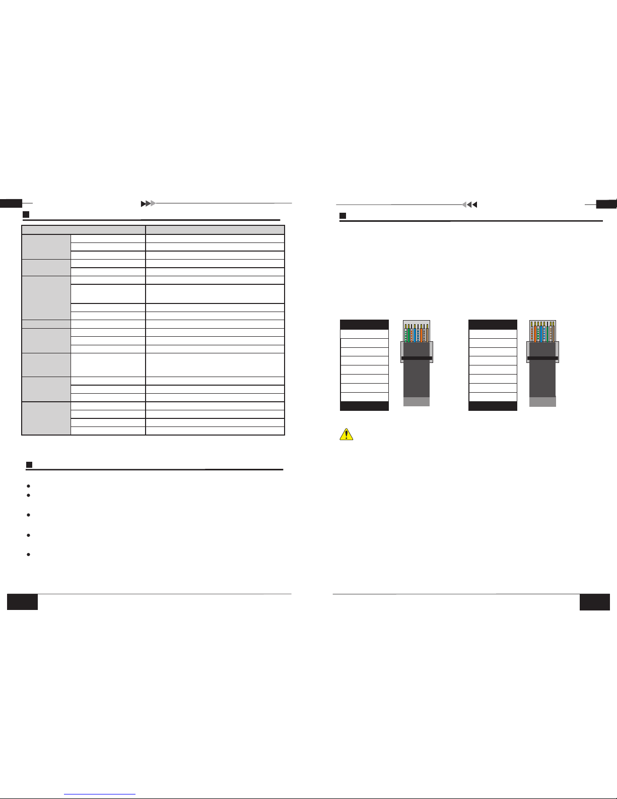
Ins trume nts to be used : w ire cri mper, netwo rk tes ter, Wire seq uence of RJ4 5 plug should
con form wi th EIA/ TIA56 8A or 568 B stand ards.
1) Pl ease re move 2c m long th e insul ating l ayer an d bare th e 4 pairs U TP cabl e;
2) Se parat e the 4 pai rs UTP ca ble and s traig hten th em;
3) Li ne up the 8 p ieces o f cable s per EIA /TIA 56 8A or 568 B;
4) Cu t off the c ables t o leave 1 .5cm ba re wire ;
5) Pl ug 8 cabl es into R J45 plu g, make s ure eac h cable i s in each p in;
6) Us e the wir e crimp er to cri mp it;
7) Re peat ab ove 5 ste ps to mak e the ano ther en d;
8) Us e netwo rk test er to tes t the cab le whet her it wo rks.
RJ45 Maki ng M et ho d
Pin Color
Whi te/Gr een
Gre en
Blu e
Whi te/Or ange
Whi te/Bl ue
Whi te/Br own
Ora nge
Bro wn
1
2
3
4
5
6
7
8
Pin Color
1
2
3
4
5
6
7
8
Whi te/Gr een
Gre en
Blu e
Whi te/Or ange
Whi te/Bl ue
Whi te/Br own
Ora nge
Bro wn
EIA /TIA 56 8A
EIA /TIA 56 8B
Notice
Whe n choos e RJ45 ma ke sure i f one end i s EIA/T IA568 A,the o ther en d shoul d also be E IA/TI A568A .
Whe n choos e RJ45 ma ke sure i f one end i s EIA/T IA568 B,the o ther en d shoul d also be E IA/TI A568B .
Spe cific ation c hange w ill not b e notic ed
 Loading...