

IPOne AIRGATE5031 Users Manual
IPOne 54Mbps Wireless LAN Access Point
User’ s Manual ver. 1.1.4e
IP ONE, Inc.
Gusang Bldg. 2F, 1009-5, Daechi-dong, Gangnam-gu, Seoul, 135-280, Korea
http://www.ipone.co.kr
Tel: +82-2-3011-0947
E-mail: sales_marketing@ipone.co.kr
THE SPECIFICATIONS AND INFORMATION REGARDING THE PRODUCTS IN THIS
MANUAL ARE SUBJECT TO CHANGE WITHOUT NOTICE. ALL RIGHTS RESERVED.
☞ Models subjected to this document: AG3000/5000/503X series.

The instructions furnished the user shall include the following or
similar statement, placed in a prominent location in the text of the
manual.
INFORMATION TO THE USER (Part 15.105(b))
For Class B digital device
INFORMATION TO THE USER
This equipment has been tested and found to comply with the limits for a Class B digital device,
pursuant to part 15 of the FCC Rules. These limits are designed to provide reasonable protection
against harmful interference in a residential installation. This equipment generates uses and can
radiate radio frequency energy and, if not installed and used in accordance with the instructions,
may cause harmful interference to radio communications. However, there is no guarantee that
interference will not occur in a particular installation. If this equipment does cause harmful
interference to radio or television reception, which can be determined by turning the equipment
off and on, the user is encouraged to try to correct the interference by one more of the following
measures:
-Reorient or relocate the receiving antenna.
-Increase the separation between the equipment and receiver.
-Connect the equipment into an outlet on a circuit different from that to which
the receiver is connected.
-Consult the dealer or an experienced radio/TV technician for help.
WARNING (Part 15.21)
Changes or modifications not expressly approved by the manufacturer could void the user’s
authority to operate the equipment.
“Note: The manufacturer is not responsible for any Radio or TV interference caused by
unauthorized modifications to this equipment. Such modifications could void the user’s
authority to operate the equipment.”
“CAUTION: RF Exposure to Radio Frequency Radiation.
This equipment must be installed and provided minimum seperatiom distance of 20cm from the body of user and
near by person. In addition to seperation distance, this device cannot be transmitted and operating in conjuction with
any other transmitter or antenna.

IPOne 54Mbps AP User’s Guide
CONTENTS
ABBREVIATION............................................................................................................................iii
CHAPTER 1. Wireless LAN Overview ..........................................................................................1
CHAPTER 2. AP Architecture and Installation .............................................................................. 2
2.1 AP Components...............................................................................................................2
2.2 AP View............................................................................................................................ 2
2.2.1 AP Front.................................................................................................................2
2.2.2 AP Rear..................................................................................................................3
2.3 AP Installation..................................................................................................................3
2.3.1 Notice before Installation.......................................................................................3
2.3.2 Installation..............................................................................................................4
2.3.3 Notice when you use ............................................................................................. 4
CHAPTER 3. AP Software Configurations....................................................................................6
3.1 IPOne WOS Key Features............................................................................................... 7
3.2 AP Management System Access.....................................................................................8
3.2.1 AP Access and TCP/IP Setting using HyperTerminal............................................8
3.2.2 AP Access using Web Browser............................................................................12
3.2.4 AP Access using Telnet........................................................................................14
3.3 Basic Settings ................................................................................................................ 15
3.3.1 Configuring Operating Mode and TCP/IP............................................................15
3.3.2 Configuring Interface and Application Port..........................................................18
3.3.3 QoS Configurations ............................................................................................. 20
3.4 Configuring DHCP Server.............................................................................................. 23
3.5 Configuring Wireless LAN.............................................................................................. 25
3.5.1 5GHz IEEE 802.11a Radio Configuration............................................................ 25
3.5.2 2.4GHz IEEE 802.11g Radio Configuration......................................................... 28
3.6 Configuring Authenti cation and Accounting ................................................................... 31
3.7 Configuring SNMP ......................................................................................................... 37
3.8 Configuring MAC Filtering and ACRM ...........................................................................39
3.8.1 MAC Filtering.......................................................................................................39
3.8.2 ACRM (Access Control for Remote Management)..............................................41
3.9 Configuring Mobile IP Foreign Agent .............................................................................43
3.10 Configuring Management Functions............................................................................ 48
Copyright © 2004 All rights reserved by IPOne, Inc.
i

3.10.1 Authenticated Users Information........................................................................ 49
3.10.2 Updating Firmware.............................................................................................51
3.10.3 System Log........................................................................................................ 54
3.10.4 System Reboot and Logout...............................................................................55
CHAPTER 4. AP Configurations According to Operation Mode.................................................56
4.1 AP Configurations in Bridge mode.................................................................................56
4.2 AP Configurations in Routed mode................................................................................56
4.3 AP Configurations in NAT mode.....................................................................................57
IPOne 54Mbps AP User’s Guide
Copyright © 2004 All rights reserved by IPOne, Inc.
ii

IPOne 54Mbps AP User’s Guide
ABBREVIATION
AAA : Authentication, Authorization, Accounting
ADSL : Asymmetric Digital Subscriber Line
AP : Access Point
BSS : Basic Service Set
CCK : Complimentary Code Keying
CTS: Clear To Send
DBPSK : Differential Binary Phase Shift Keying
DC : Direct Current
DHCP : Dynamic Host Configuration Protocol
DNS : Domain Name Service
DTIM : Delivery Traffic Indication Map
DQPSK : Differential Quadrature Phase Shift Keying
EAP : Extensible Authentication Protocol
ESSID : Extended Service Set Identity
FA: Foreign Agent
GMT : Greenwich Mean Time
HA: Home Agent
HTTP: Hypertext Transfer Protocol
IP : Internet Protocol
IAPP : Inter Access Point Protocol
ICMP: Internet Control Message Protocol
ID: Identity
IEEE : Institute of Electrical and Electronics Engineers
LAN : Local Area Network
LED: Light Emitting Diode
MAC : Media Access Control
MIP: Mobile IP
MN: Mobile Node
NAT : Network Address Translation
NAS : Network Access Server
PC : Personal Computer
PCMCIA : Personal Computer Memory Card International Association
POD : Pull Out Detection
Copyright © 2004 All rights reserved by IPOne, Inc.
iii

PoE : Power over Ethernet
PPP : Point-to-Point Protocol
PPPoE : Point-to-Point Protocol over Ethernet
PS : Power Save
RADIUS : Remote Authentication Dial In User Service
RF : Radio Frequency
RTS : Request To Send
Rx : Receive
SNMP : Simple Network Management Protocol.
SNTP : Simple Network Time Protocol
SSID : Service Set Identity
TCP : Transmission Control Protocol
TFTP : Trivial File Transfer Protocol
Tx : Transmit
IPOne 54Mbps AP User’s Guide
UDP : User Datagram Protocol
USB : Universal Serial Bus
WAN : Wide Area Network
WEP : Wired Equivalent Privacy
WLAN : Wireless Local Area Network
Copyright © 2004 All rights reserved by IPOne, Inc.
iv
IPOne 54Mbps AP User’s Guide
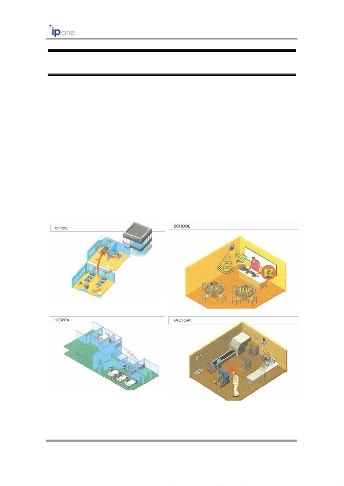
CHAPTER 1. Wireless LAN Overview
Wireless LAN (WLAN) refers to a LAN that uses high frequency radiowave instead of cables
for inter-node communications. WLAN operation is specified in IEEE 802.11. Unlimited access
to business applications is becoming essential. WLANs are increasingly being used to provide
flexible network connectivity. WLAN solutions are typically deployed internally, usually within an
office or factory environment, although they can be installed externally to provide short-range
connectivity to mobile users.
WLAN benefits include:
Increased mobility
Fast deployment
Network access where cabling is difficult
Connectivity for temporary networks
Fig. 1.1.1 Wireless LAN examples
Copyright © 2004 All rights reserved by IPOne, Inc.
1

IPOne 54Mbps AP User’s Guide
CHAPTER 2. AP Architecture and Installation
2.1 AP Components
Please check the following components before installation:
① Access Point
② Antenna
③ Power Adaptor
④ RS-232 Cable (option)
⑤ CD (User’s Manual)
2.2 AP View
2.2.1 AP Front
Fig. 2.2.1 AP Front
Copyright © 2004 All rights reserved by IPOne, Inc.
2
Num LED Name Color Description
① PWR Green Power status
② WL1 Green Tx/Rx dat a to/from WLAN port
WL2 Green Tx/Rx dat a to/from WLAN port 2
③
(Internal for Dual-mode AP)
LAN Green Tx/Rx dat a to/from Ethernet LAN port
④
(Internal for 2 port Ethernet AP)
⑤ WAN Green Tx/Rx dat a to/from Ethernet WAN port
⑥ SEC Green Encryption status
IPOne 54Mbps AP User’s Guide
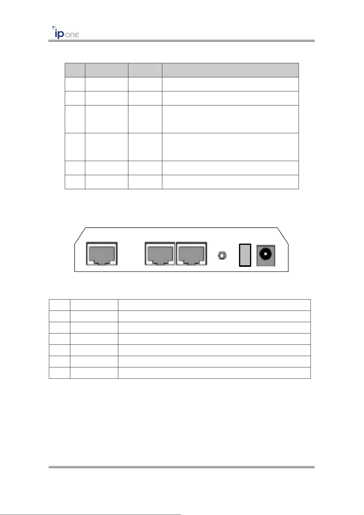
2.2.2 AP Rear
WAN CONSOLE LAN
Fig. 2.2.2 AP Rear (Model dependent)
Num Name Description
①
②
③
④
⑤
⑥
WAN RJ-45 Ethernet Connect
CONSOLE RS-232 Serial Port
LAN RJ-45 Ethernet Connector (Internal for 2 port Ethernet AP)
RESET Factory Reset Switch
S/W Power ON/OFF Switch
POWER DC Power Connector
POWERS/W
RESET
2.3 AP Installation
2.3.1 Notice before Installation
We recommend you to avoid these places where may be cause of performance decline or
trouble:
Copyright © 2004 All rights reserved by IPOne, Inc.
3

① Places with high humidity or wet condition
② Places with extreme temperature (too hot or too cold)
③ Places where change of temperature is extreme
④ Places with a lot of dusts
⑤ Places sealed with thick walls or still structure which cause high interference
IPOne 54Mbps AP User’s Guide
2.3.2 Installation
STEP 1 Attach UTP Ethernet Cable
Attach UTP Ethernet cable to AP’s RJ-45 connector and connect the other side of the cable
to network equipments such as Router or Hub.
STEP 2 Attach RS-232C Serial Cable
Attach RS-232C serial cable to the AP and PC. The parameters of AP can be configured
through connection of RS-232C serial cable to the PC (Refer Chapter 3).
STEP 3 Supply Power
Plug in the DC output to AP’s power port. Make sure that the “Power” LED is on. If the
“Power” LED is not on, please check the connections of the power code.
☞ Notice: Use the supplied power adapter (DC 5V, 2A) only to prevent the permanent failure of
AP.
☞ Notice: Don’t use both DC power and PoE power at the same time.
☞ PoE usage: The PoE (Power over Ethernet) is the equipment that both power and data are
supplied throughput Ethernet cable. Plug in the power adapter to DC in of PoE and the Ethernet
cable to Data in of PoE. Attach UTP Ethernet cable to AP’s RJ-45 connector and connect the
other side of the cable to Data & Power Out of PoE (Internal for PoE supported models).
STEP 4 Confirm Installation
Change settings of AP referring User’s Guide. Insert a wireless LAN card into your PC. Enter
the same ESSID that you have set for the AP, using the wireless LAN card utility running on
your PC. Check the signal strength of wireless link on the wireless LAN card utility.
2.3.3 Notice when you use
We recommend you to avoid the followings when you use:
① Do not disassemble on your own.
Copyright © 2004 All rights reserved by IPOne, Inc.
4

② Do not drop the product or give excessive impact.
③ Do not use any parts or components, which are not provided.
④ Use only the power adapter provided.
⑤ Use the PoE only for PoE supported models.
IPOne 54Mbps AP User’s Guide
Copyright © 2004 All rights reserved by IPOne, Inc.
5

IPOne 54Mbps AP User’s Guide
CHAPTER 3. AP Software Configurations
☞ This software configuration guide describes how to configure AG5031DU-AN2 Access
Points using web-based management system (WMS) or console-based management
system (CMS). This guide can be subject to other 54Mbps Access Points if we don’t
comment specific notice.
☞ This software configuration guide is based on IPOne Access Point software, Wireless
LAN Operating System (WOS) version 1.1.14. However, this guide can be subject to other
higher WOS versions if we don’t comment specific notice.
Written by Jae-Woo So
Management Options
You can use the access point management system throughput the following interfaces:
A web-browser interface
A command-line interface (CLI)
Simple Network Management Protocol (SNMP)
Copyright © 2004 All rights reserved by IPOne, Inc.
6

IPOne 54Mbps AP User’s Guide
3.1 IPOne WOS Key Features
The key features of IPOne WOS are as follows:
Authentication, Security, Billing
Authentication IEEE 802.1x based authentication/security
MAC address authentication
WPA
Security 64/128/152 bit static WEP, 64/128 bit dynamic WEP, WPA
Billing and Local Services RADIUS accounting
Session/Idle-timeout, Lost carrier detection
WEB-Redirection, white list support
Private IP allocation for guest uses
Notify user’s IP address to server
Networking and Control
IP sharing NAT
Network Protocol TCP/IP, IEEE 802.1d transparent bridge, 802.1x
DHCP server/client/relay, PPPoE
Access Control MAC address filtering,
Control of the maximum number of association
Wireless Radio Control Radio transmission power control,
Automatic change of transmit rate,
Automatic channel selection
Roaming
L2 roaming Seamless roaming between AP’s, IEEE 802.11f IAPP support
L3 roaming
(Subnet roaming)
Quality of Service
Downstream QoS IEEE 802.1p based downstream QoS support
Management
Mobile IP foreign agent support (RFC2002).
☞ This function is included only in Enterprise high-level AP
product (AG5031DU series).
SNMP/MIB SNMP MIB (MIB II, WLAN MIB, 802.1x MIB, 802.1d Bridge MIB,
Enterprise MIB), Trap message
Local Configurations ITU-T V.24 (EIA-RS232C), RJ-45 Port
Remote Configurations Telnet, HTTP, SNMP, Web-based management
Firmware Upgrade Upgrade via TFTP, FTP, HTTP
Copyright © 2004 All rights reserved by IPOne, Inc.
7
IPOne 54Mbps AP User’s Guide
3.2 AP Management System Access
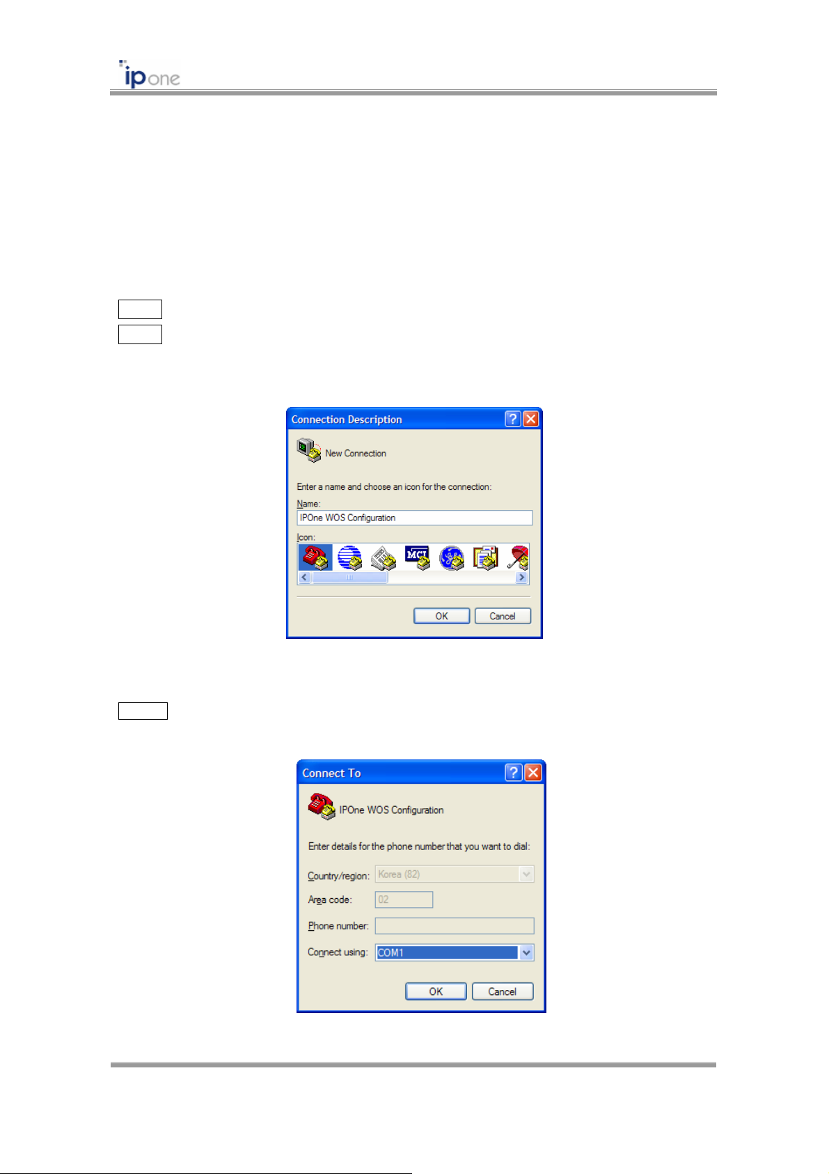
3.2.1 AP Access and TCP/IP Setting using HyperTerminal
Attach RS-232C serial cable to the AP and PC. Execute “HypterTerminal” program on
your MS-Windows by following the steps.
STEP1 Execute HyperTerminal program.
STEP2 After executing the HyperTerminal, the following window will be displayed on MS-
Windows. As displayed above, type “IPOne WOS Configuration” in the name field, and
click [OK] button. You can enter any name you wish for the connection.
Fig. 3.2.1 HypterTerminal Initial Screen
STEP 3 Select the modem port as shown in the window below, and click [OK] button. In most of
the cases, select either “Direct to Com1” or “Direct to Com2.”.
Fig. 3.2.2 HypterTerminal Select modem port
Copyright © 2004 All rights reserved by IPOne, Inc.
8
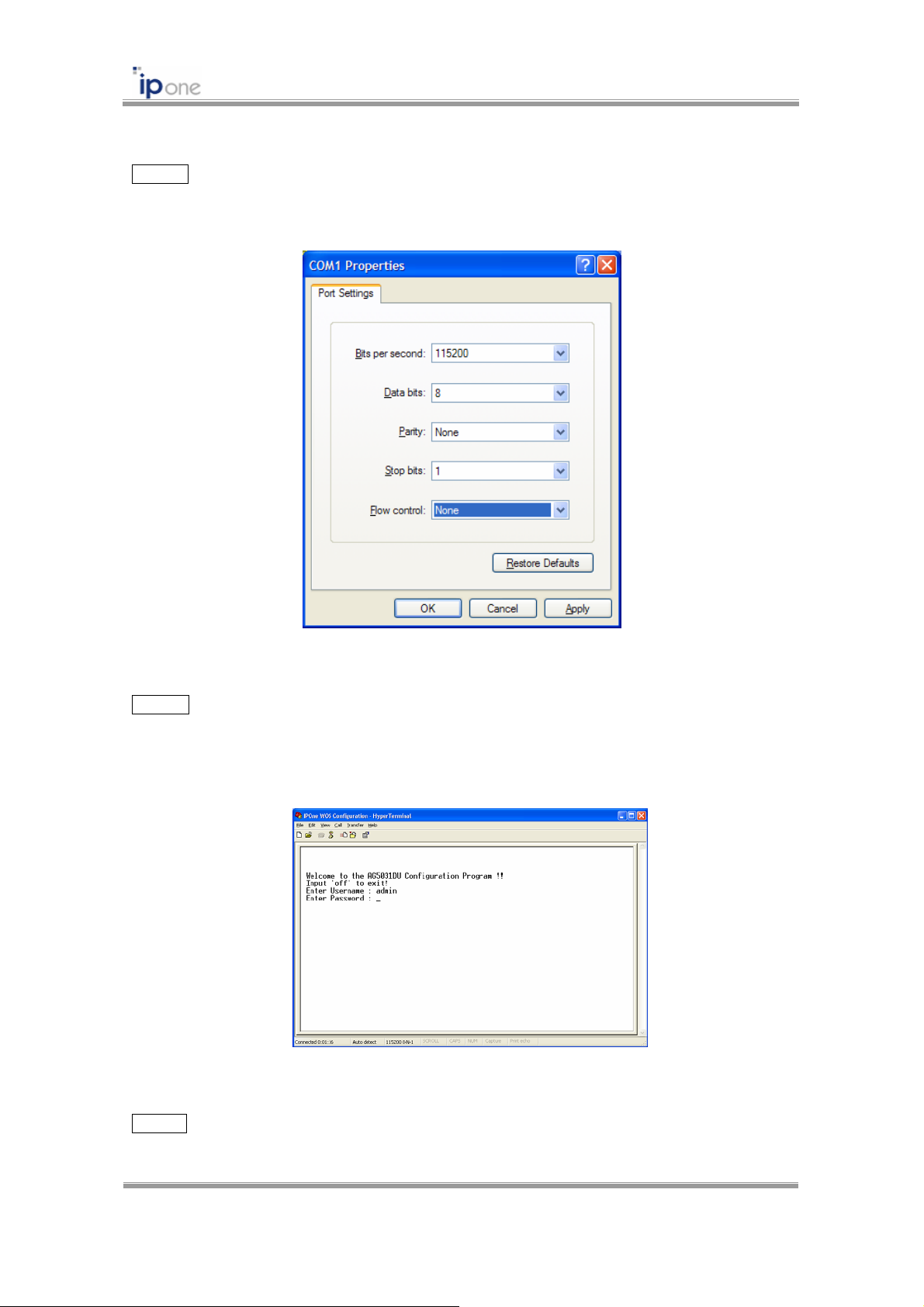
STEP 4 You will view the following window and must set the properties of the selected COM
port as shown below. Click [OK] button.
IPOne 54Mbps AP User’s Guide
Fig. 3.2.3 HypterTerminal Port Settings
STEP 5 If all the steps above are executed correctly, then the following login prompt will be
displayed on the HyperTerminal window. The default username and password is “admin” and
“admin” respectively.
Fig. 3.2.4 HyperTerminal AP CMS Login
STEP 6 When username and password are correctly entered, the following [Status] menu of AP
CMS (Console-based Management System) appears on the HyperTerminal window.
Copyright © 2004 All rights reserved by IPOne, Inc.
9
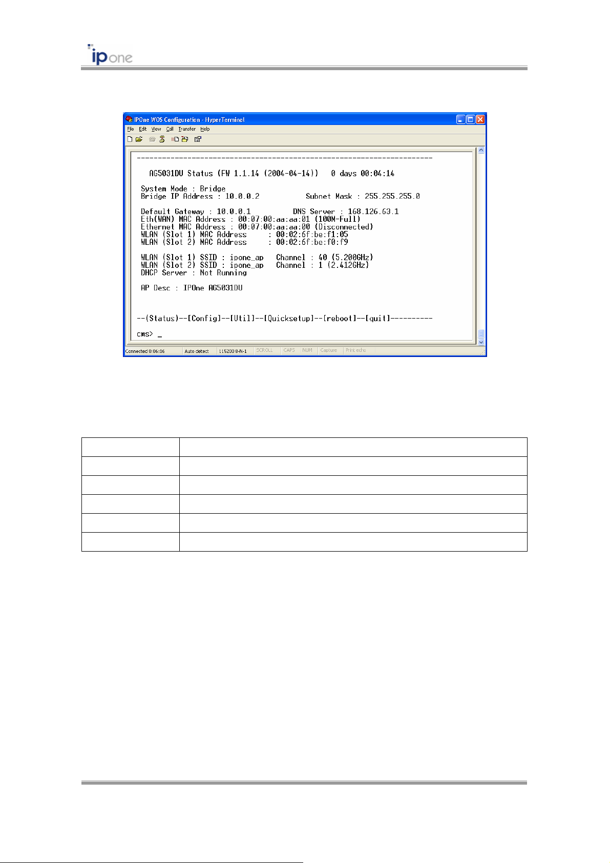
IPOne 54Mbps AP User’s Guide
Fig. 3.2.5 HyperTerminal AP CMS Status
In AP CMS, the command is the follows:
Command Description
S <enter> AP Status
C <enter> AP Configurations
U <enter> AP Management Functions
reboot <enter> Reboot
quit <enter> Logout
Copyright © 2004 All rights reserved by IPOne, Inc.
10
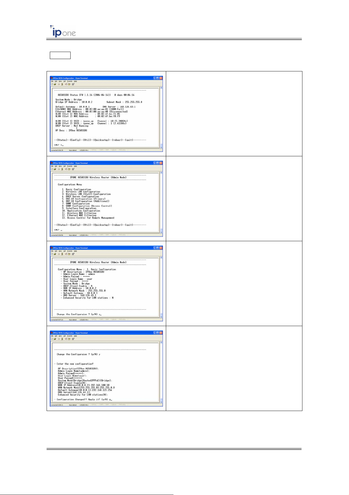
STEP 7 In AP CMS, configure TCP/IP information by following the steps.
① Enter the command “C” to move [Config]
menu of CMS.
② Enter the command “1” to select the menu
of [1. Basic Configuration].
IPOne 54Mbps AP User’s Guide
③ Enter the command “y” to change
configurations.
④ Enter the proper values. Then, enter the
command “y” to apply them. If you just enter
without input of the proper value, the default
value keeps.
Fig. 3.2.6 HyperTermal TCP/IP Settings
Copyright © 2004 All rights reserved by IPOne, Inc.
11
IPOne 54Mbps AP User’s Guide
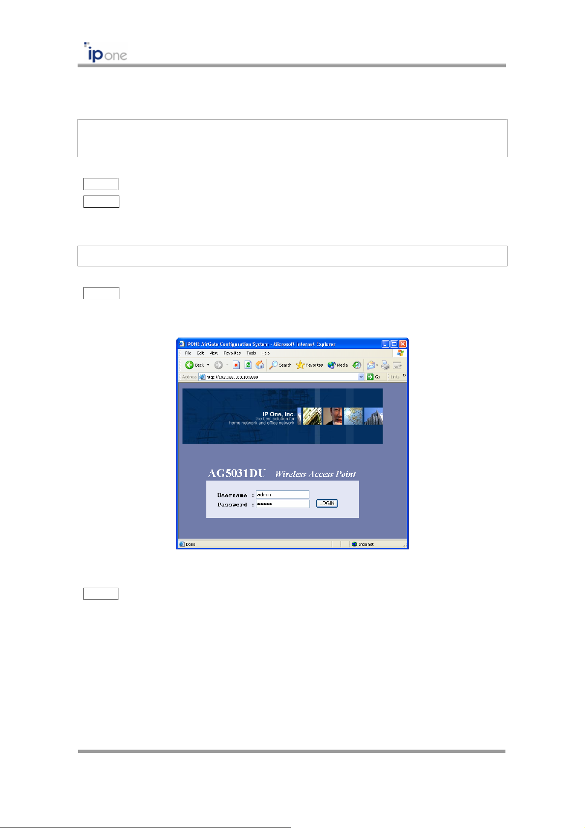
3.2.2 AP Access using Web Browser
☞ Default IP address of the AP is “10.0.0.2.” This example assumed that you change the IP
address into “192.168.110.10” by using HyperTerminal.
STEP 1 Open Web Browser. We recommend beyond IE 5.0.
STEP 2 Enter AP’s IP address and Port number on “Address” of the Web Browser to access
AP’s WMS (Web-based Management System). The default HTTP port number is 8899.
http://[AP’s IP Address]:8899
STEP 3 Enter Username and Password. The default username and password is “admin” and
“admin” respectively.
Fig. 3.2.7 AP WMS Login
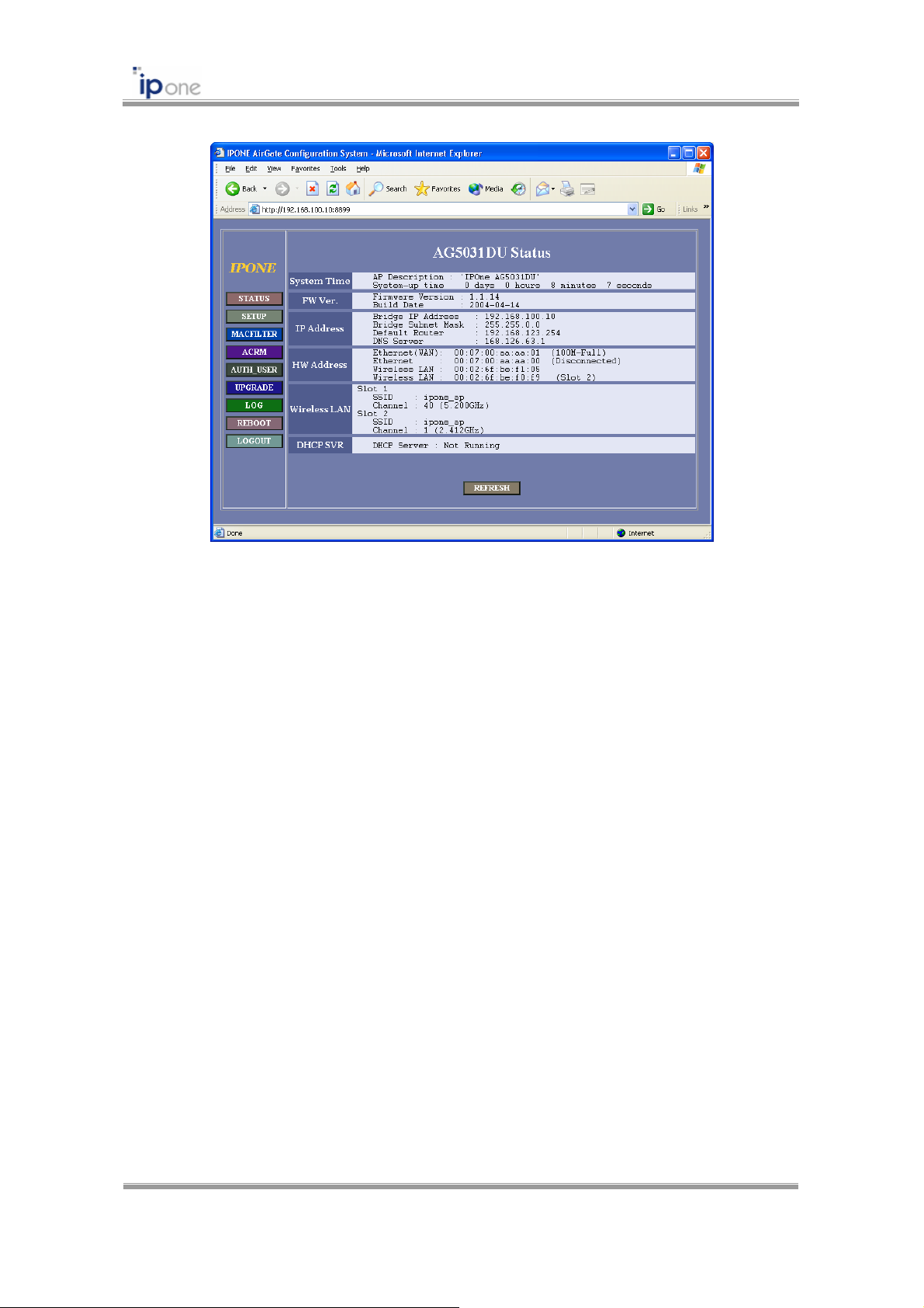
STEP 4 When username and password are correctly entered, the following [Status] menu of AP
WMS appears.
Copyright © 2004 All rights reserved by IPOne, Inc.
12
IPOne 54Mbps AP User’s Guide
Fig. 3.2.8 AP WMS Status
Copyright © 2004 All rights reserved by IPOne, Inc.
13
IPOne 54Mbps AP User’s Guide
3.2.4 AP Access using T elnet
☞ Default IP address of the AP is “10.10.10.2.” This example assumed that you change the IP
address into “192.168.110.10” by using HyperTerminal.
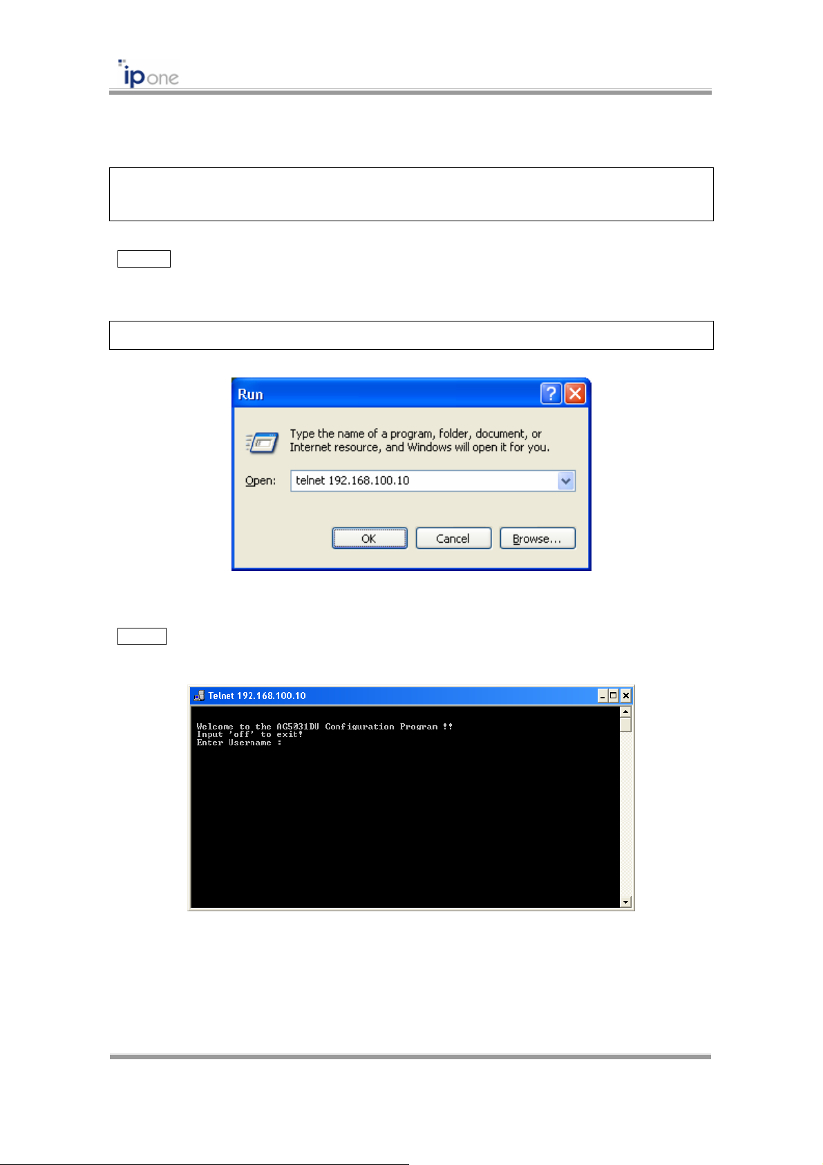
STEP 1 Open “Run” on [Start] menu of MS-Windows. Enter the IP address for Internet
Connection as following Example. Click [OK] button.
telenet [AP’s IP address]
Fig. 3.2.9 AP access using Telnet
STEP 2 Telnet order window appears, and please refer to “AP Access using HyperTerminal.”
Fig. 3.2.10 Telnet AP CMS Login
Copyright © 2004 All rights reserved by IPOne, Inc.
14
 Loading...