

IPOne AIRGATE2000K User Manual

IPOne AirGate Wireless Series
AirGate 2000K
2003. 09
IPone In c
IPOne
www.IPOne.co.kr
1

IPOne AirGate Wireless Series
Contents
1. AP Overview⋯⋯⋯⋯⋯⋯⋯⋯⋯⋯⋯⋯⋯⋯⋯⋯⋯⋯⋯⋯⋯4
1.1 General⋯⋯⋯⋯⋯⋯⋯⋯⋯⋯⋯⋯⋯⋯⋯⋯⋯⋯⋯⋯⋯⋯⋯⋯⋯⋯⋯⋯⋯⋯⋯⋯⋯4
1.2 Configuration Diagram
1.3 AP Structure⋯⋯⋯⋯⋯⋯⋯⋯⋯⋯⋯⋯⋯⋯⋯⋯⋯⋯⋯⋯⋯⋯⋯⋯⋯⋯⋯⋯⋯⋯5
1.4 AP Components⋯⋯⋯⋯⋯⋯⋯⋯⋯⋯⋯⋯⋯⋯⋯⋯⋯⋯⋯⋯⋯⋯⋯⋯⋯⋯⋯⋯6
⋯⋯⋯⋯⋯⋯⋯⋯⋯⋯⋯⋯⋯⋯⋯⋯⋯⋯⋯⋯⋯⋯⋯ 4
2. H/W, S/W Structure⋯⋯⋯⋯⋯⋯⋯⋯⋯⋯⋯⋯⋯⋯⋯⋯⋯⋯7
2.1 Internal Block Diagram⋯⋯⋯⋯⋯⋯⋯⋯⋯⋯⋯⋯⋯⋯⋯⋯⋯7
2.2 S/W Hierarchical Structure⋯⋯⋯⋯⋯⋯⋯⋯⋯⋯⋯⋯⋯⋯⋯8
3.Console, Telnet Setup⋯⋯⋯⋯⋯⋯⋯⋯⋯⋯⋯⋯⋯⋯⋯⋯⋯9
3.1 : Setting Terminal Emulator for Console⋯⋯⋯⋯⋯⋯⋯⋯⋯⋯⋯⋯⋯9
3.2 : Connecting Telnet ⋯⋯⋯⋯⋯⋯⋯⋯⋯⋯⋯⋯⋯⋯⋯⋯⋯⋯⋯⋯⋯⋯⋯⋯⋯ 12
3.3 : AirGate2000K Setup
3.4 : Status
3.5 : Config
⋯⋯⋯⋯⋯⋯⋯⋯⋯⋯⋯⋯⋯⋯⋯⋯⋯⋯⋯⋯⋯⋯⋯⋯⋯⋯⋯⋯⋯⋯⋯⋯⋯ 13
⋯⋯⋯⋯⋯⋯⋯⋯⋯⋯⋯⋯⋯⋯⋯⋯⋯⋯⋯⋯⋯⋯⋯⋯⋯⋯⋯⋯⋯⋯⋯⋯⋯⋯13
3.6 : Util⋯⋯⋯⋯⋯⋯⋯⋯⋯⋯⋯⋯⋯⋯⋯⋯⋯⋯⋯⋯⋯⋯⋯⋯⋯⋯⋯⋯⋯⋯⋯⋯⋯⋯⋯⋯24
3.7 : Reboot⋯⋯⋯⋯⋯⋯⋯⋯⋯⋯⋯⋯⋯⋯⋯⋯⋯⋯⋯⋯⋯⋯⋯⋯⋯⋯⋯⋯⋯⋯⋯⋯⋯ 25
3.8 : Quit
………………………………………⋯⋯⋯……………………………………………25
⋯⋯⋯⋯⋯⋯⋯⋯⋯⋯⋯⋯⋯⋯⋯⋯⋯⋯⋯⋯⋯⋯⋯⋯ 12
4. Web-based Management
4.1 : Web-based Management……………………………………………………… 26
4.2 : Status
4.3 : Network Settings
4.4 : WLAN Settings
4.5 : Authentications and Billing Configuration …………………………… 30
4.6 : Other Setting for Authentications and Billing……………………… 31
4.7 : SNMP Setting
4.8 : DHCP Setting………………………………………………………………………………33
4.9 : Log………………………………………………………………………………………………34
4.10 : System Reboot………………………………………………………………………… 35
4.11 : AP Management Tool Login Password Change
4.12 : Firmware Upgrade……………………………………………………………………36
4.13 : Other Setting
4.14 : Quick Installation……………………………………………………………………… 39
…………………………………………………………………………………………………… 26
…………………………………………………………………………27
…………………………………………………………………………… 29
………………………………………………………………………………32
…………………………………………………………………………… 37
………………………………
…………………36
26
IPOne
www.IPOne.co.kr
2

IPOne AirGate Wireless Series
5. Service Opening Method
………………………………
5.1 Checkpoints before Installation…………………………………………………41
5.2 Installation……………………………………………………………………………………… 41
5.3 Work Procedures……………………………………………………………………………41
5.4 Configuration Method……………………………………………………………………42
5.5 Considerations………………………………………………………………………………42
6. Maintenance and Fault Handling
……………………
41
43
IPOne
www.IPOne.co.kr
3
1. AP Overview
1.1 General
1.1.1 Overview of Wireless LAN ( WLAN)
Wireless LAN(WLAN) refers to a LAN that uses high frequency radiowave instead of
IPOne AirGate Wireless Series
cables for inter-node communication. WLAN operation is defined in IEEE 802.11b.
transmits high-speed data up to 11 Mbps.
environment (country area) as well as in buildings and campuses, and supports data
communication with high reliability. In addition, it is easy and fast installs it. It is possible to
install WLAN even in places where it is impossible to install wired LANs, and also possible
to install it temperately.
Currently connected to ADSL network used for companies or
houses, it aims to provide the wireless LAN service through Access Point
(Integrated Access Point: hereinafter referred to as “The integrated AP”) which
combines ADSL with wireless LAN. The integrated AP, composed of ADSL Access
device and 11M Wireless Access Point, is designed to provide the wireless LAN
service over the high-speed Internet served via ADSL line.
The integrated AP, equipped with 10/T base wired port as 1 port, is designed to
configure 10/T base wired LAN without the help of other equipments.
and education fields, WLAN has shown a rapid growth.
1.2 Configuration Diagram
WLAN
WLAN can keep high speed in rural
In medical
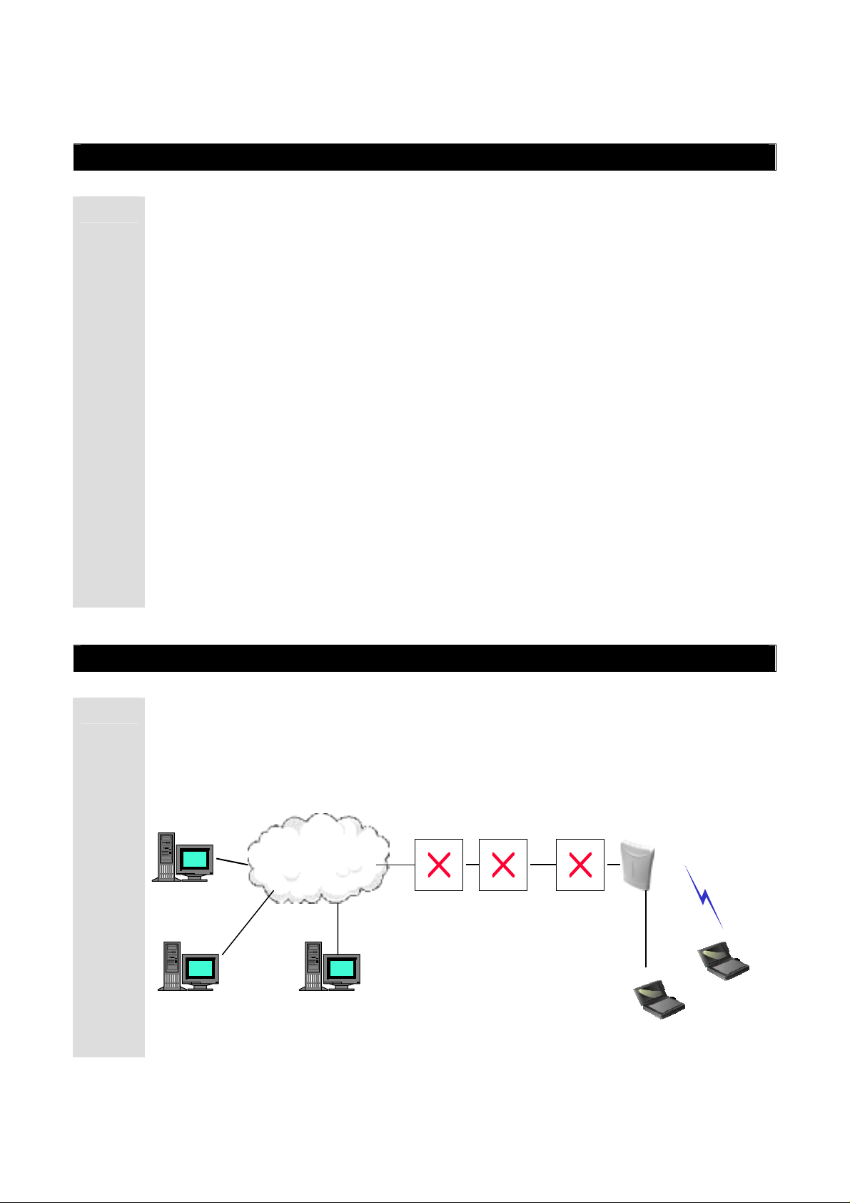
1.2.2 Network Configuration Diagram
The configuration diagram illustrates how WIMS server (authentication server),
DHCP server, NAS system and DSLAM system used by ISP can interwork with the
integrated AP in order to provide the wireless LAN service.
DHCP server
INTERNET
www.IPOne.co.kr
IPOne
AP
DSLAM NAS
4

The instructions furnished the user shall include the following or
similar statement, placed in a prominent location in the text of the
manual.
INFORMATION TO THE USER (Part 15.105(b))
For Class B digital device
INFORMATION TO THE USER
This equipment has been tested and found to comply with the limits for a Class B digital device,
pursuant to part 15 of the FCC Rules. These limits are designed to provide reasonable protection
against harmful interference in a residential installation. This equipment generates uses and can
radiate radio frequency energy and, if not installed and used in accordance with the instructions,
may cause harmful interference to radio communications. However, there is no guarantee that
interference will not occur in a particular installation. If this equipment does cause harmful
interference to radio or television reception, which can be determined by turning the equipment
off and on, the user is encouraged to try to correct the interference by one more of the following
measures:
-Reorient or relocate the receiving antenna.
-Increase the separation between the equipment and receiver.
-Connect the equipment into an outlet on a circuit different from that to which
the receiver is connected.
-Consult the dealer or an experienced radio/TV technician for help.
WARNING (Part 15.21)
Changes or modifications not expressly approved by the manufacturer could void the user’s
authority to operate the equipment.
“Note: The manufacturer is not responsible for any Radio or TV interference caused by
unauthorized modifications to this equipment. Such modifications could void the user’s
authority to operate the equipment.”
“CAUTION: RF Exposure to Radio Frequency Radiation.
This equipment must be installed and provided minimum seperatiom distance of 20cm from the body of user and
near by person. In addition to seperation distance, this device cannot be transmitted and operating in conjuction with
any other transmitter or antenna.

1.3 AP Structure
1.3.1 AP Structure
1.3.1.1 AP Front View
IPOne AirGate Wireless Series
① ② ③ ④ ⑤
AP LED LAYOUT
No. LED Name Color LED Operation State
On
① Wireless Green
Off
On/Off Repeat WLAN Data Communication
② WLAN Green
Off No WLAN Data Communication
On
③ Power Green
Off
On/Off 반복
④ Ethernet Green
Off
Wireless LAN is connected
Wireless LAN connection is
stopped
Power is already supplied
Power is not supplied
Ethernet data communication
Ethernet data communication is
stopped
⑤ WLAN Green
www.IPOne.co.kr
On
IPOne
Ethernet is connected
5
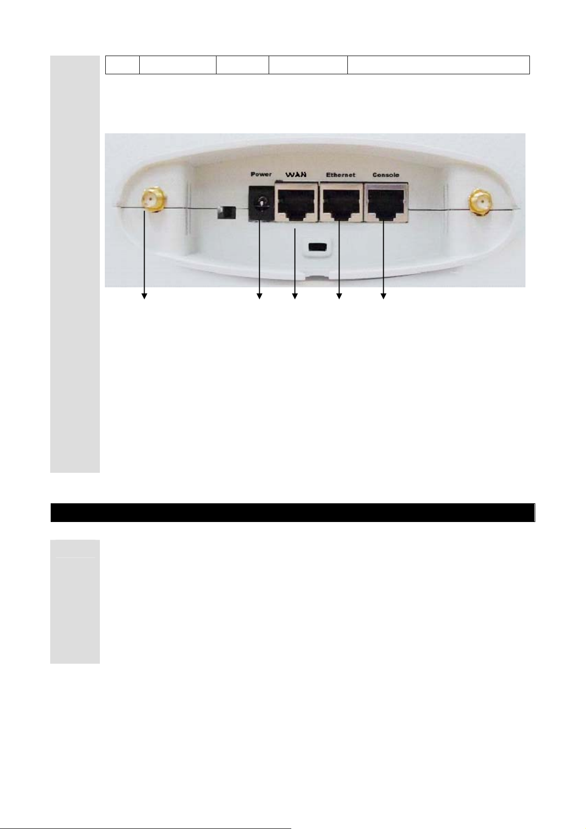
1.3.1.2 AP Rear View
Off
IPOne AirGate Wireless Series
Ethernet connection is stopped
1.4 AP Components
1.4.1 AP Components
Check AP products components before installing the AP
① ② ③ ④ ⑤
① Dipole Antenna Connector
② DC Power Connector
③ RJ-45 Ethernet Connector
④ RJ-45 Ethernet Connector
⑤ RJ-45 Serial Port
① Access Point Set
② Outer Antenna
③ Power Adaptor
④ RS- 232 Cable
⑤ Manual CD-ROM
IPOne
www.IPOne.co.kr
6

2. H/W, S/W Structure
2.1
Internal Block Diagram
2.1 Internal Block Diagram
The figure below shows Internal hardware block diagram.
CPU
S5N8947
MII Interface
100/10BaseT
Ethernet SW
IPOne AirGate Wireless Series
RJ-45 Connector
RJ-45 Connector
RS-232
RJ-45 Connector
Driver
SDRAM 16MByte
Data 0~32
PCMCIA
WLAM Module
ROWER
1.8V/3.3V
To Need
Reset & Clock
To Need
IPOne
www.IPOne.co.kr
7
2.2
S/W Hierarchical Structure
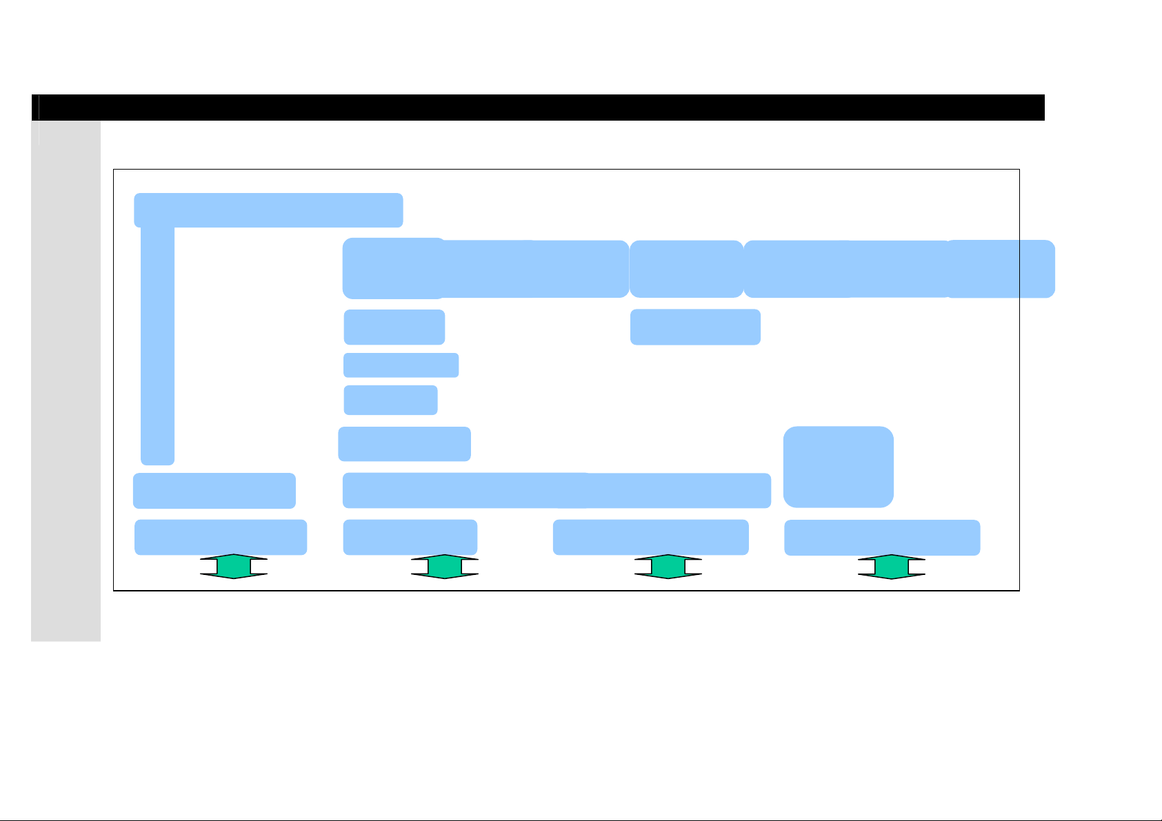
2.2.1 S/W Hierarchical Structure
The figure blow shows software hierarchical structure of our AP.
IPOne AirGate Wireless Series
System Management Function
Console Device Driver
PC Console WLAN LAN Terminal Ethernet Terminal
FTP
TCP
IP
802.1d Bridge
802.1x EAP-MD5
Wireless LAN Device Driver
802.11b Interface Ethernet ControllerSerial Interface
HTTP
WEB/
Telnet
Server
Ethernet Device D r iv er
DHCP
UDP
SNMP
Ethernet
Device
Driver
Ethernet Controller
RADIUS
WAN
TFTP
IPOne
www.IPOne.co.kr
8

IPOne AirGate Wireless Series
3. Console, Telnet
3.1 : Setting Terminal Emulator for Console
There are various terminal emulators as commercial products. Amo ng them, this chapter
Setup
describes ‘Hyper Terminal’ embedded in Window that is the most widely used.
If you want to execute Hyper Terminal, click ‘Start’ -> ‘Program’-> ‘Auxiliary Program’->
‘Communication’->’Hyper Terminal’ in order.
3.1.1 Hyper Terminal Execution Screen
If you execute hyper terminal, name dialog box for ‘Connection’ appears as shown in the
:
figure below. At this time, set a desired name.
3.1.2 Connection Target
:
In Connection Target dialog box, enter Serial port to be connected. In general,
Com1/Com2 are used, and Com1 is used in most cases.
IPOne
www.IPOne.co.kr
9
IPOne AirGate Wireless Series
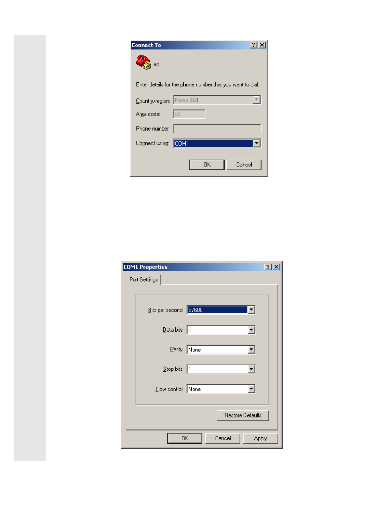
3.1.2 Entry Information Dialog Box
:
After Entry Information Dialog box appears, fill out the following items.
i Bit/Sec : 57600
i Databit : 8
i Parity : None
i Stopbit : 1
i Flow Control : None
IPOne
www.IPOne.co.kr
10
IPOne AirGate Wireless Series
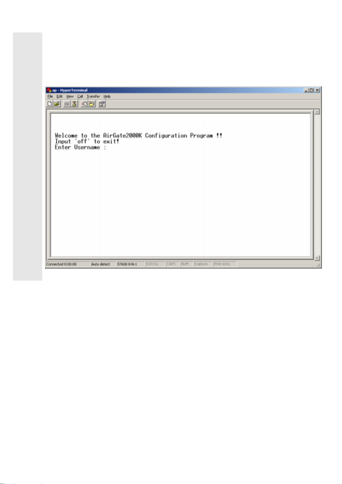
3.1.4 Login
After setting, login screen appears as shown below. An initial Username/Password are as
:
follows.
i Initial Username : admin
i Initial Password : admin
IPOne
www.IPOne.co.kr
11

3.2 : Connecting Telnet
IPOne AirGate Wireless Series
i
If you want to connect to AP through Telnet for the purpose of management, be sure
to know AP IP address. AP’s default IP Address is 10.0.0.2 and default port number is
No. 23 (Telnet default port). Example of connection is as follows.
Example) Enter the following command in Command Prompt.
C:\>telnet 10.0.0.2
To Provide wireless LAN service by installing APs, you have to be provided with the following items by the
network manager.
①
AP Operation Mode: Bridge mode, Routed mode, PPPoE mode
②
External Network Connection Mode: Fixed IP, DHCP, or ADSL(PPPoE)
③
AP IP address and network mask address
④
Basic gateway address of AP, and DNS server address
⑤ Wireless LAN SSID, channels used, and encryption status
⑥ Authentication/billing Information, radius server address, port, and secret key
Network management server address
3.3 : AirGate 2000K Setup
AirGate2000K has physical interface such as one wireless interface and two Ethernet
interfaces. One of the two Ethernet interfaces is ‘WAN’ interface, and the other is ‘LAN’
interface. When installing AirGate2000K, connect backbone network coming from the
outside to ‘WAN’ port. If ‘WAN’ port and ‘LAN’ port are changed when installed, it might
cause serious effects on some functions. Thus, be sure to check ‘WAN’ port and ‘LAN’ port
before installation.
Example) If there is an UTP cable connected through Kornet netwo rk, connect it to ‘WAN’
port, and connect internal LAN user’s (wired) PC to ‘LAN’ port.
Internet
WAN
LAN Console
User PC
IPOne
www.IPOne.co.kr
12
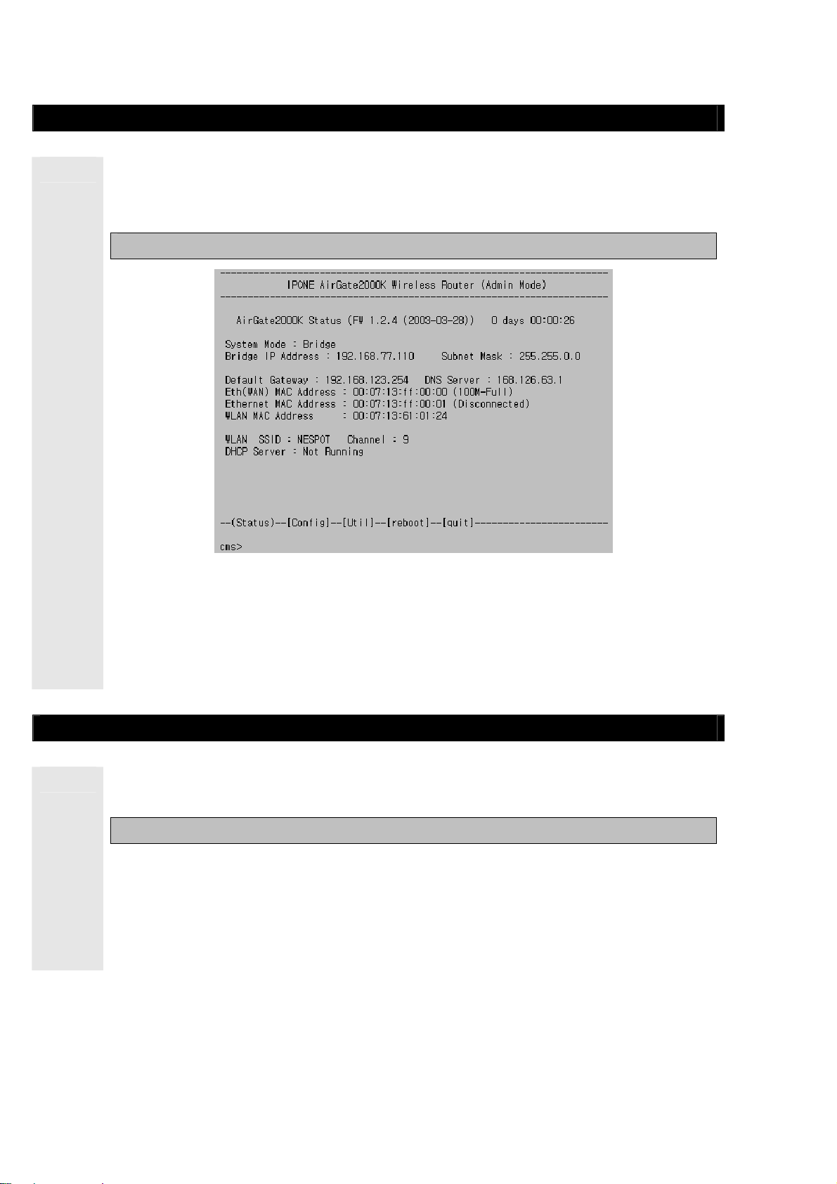
3.4 : Status
IPOne AirGate Wireless Series
In ‘Status’, you can view system setup information. If you normally log on through
Console and Telnet, the page below appears first. If you want to see ‘Status’, enter ‘s’ or
‘status’.
Ex : cms>s or cms>status
In ‘Status’ as shown in the figure below, you can search firmware version (ex: FW
1.2.4), system uptime, ADSL, network setup, wireless LAN setup, interface information
and the status of DHCP Server. After setting to subscriber ’s environment, you can check
the results in ‘Status’. For further information on setup, refer to 3.5 ‘Config’.
3.5 : Config
In ‘Config’, you can set up all AP functions. If you want to set up AP in ‘Config’, enter ‘c’ or
‘config’.
Ex: cms>c or cms>config
If you want to set the appropriate menu in ‘Config’, enter the appropriate menu number, and
enter ‘Y’ if current setup status for ‘Change Setup’ appears, and then set according to each
step. If you enter wrong number by mistake, enter ‘n’ if ‘Change Setup’ is shown.
Note! Before you set up AP in ‘Config’ menu, be sure to be familiar to this manual. If
you change a part of settings without permission, the system might be in malfunction.
IPOne
www.IPOne.co.kr
13
 Loading...