

IP-Ninjar NJR-CTB User Manual
IP-NINJAR Management and Control Box
NJR-CTB
<User’s Guide>
Ver.1.1.1
● Thank you for choosing our Digital Multi Switcher.
● To ensure the best performance of this product, please read this User’s Guide fully and carefully before
using it and keep this manual beside the product.
IDK Corporation

NJR-CTB User’s Guide
Trademarks
Blu-ray Disc and Blu-ray are trademarks of Blu-ray Disc Association.
The terms HDMI and HDMI High-Definition Multimedia Interface, and the HDMI Logo are trademarks or
registered trademarks of HDMI Licensing Administrator, Inc. in the United States and other countries.
All other company and product names mentioned in this manual are either registered trademarks or
trademarks of their respective owners. In this manual, the “®” or “™” marks may not be specified.
2

NJR-CTB User’s Guide
Before reading this manual
● All rights reserved.
● Some of the contents in this User’s Guide such as product appearance in diagrams, menu operations,
communication commands, and so on may differ depending on the version of the product.
● This User’s Guide is subject to change without notice. You can download the latest version from IDK’s
website at: http: //www.idkav.com
The reference manual for the NJR-CTB consists of the User’s guide (this document) and Command guide.
Please download these guides from the website above.
FCC STATEMENT
This equipment has been tested and found to comply with the limits for a Class A digital device, pursuant to
part 15 of the FCC Rules. These limits are designed to provide reasonable protection against harmful
interference when the equipment is operated in a commercial environment. This equipment generates, uses,
and can radiate radio frequency energy and, if not installed and used in accordance with the instruction
manual, may cause harmful interference to radio communications. Operation of this equipment in a residential
area is likely to cause harmful interference, in which case the user will be required to correct the interference
at their own expense.
CE MARKING
This equipment complies with the essential requirements of the relevant European health, safety and
environmental protection legislation.
WEEE MARKING
Waste Electrical and Electronic Equipment (WEEE), Directive 2002/96/EC
(This directive is only valid in the EU.)
This equipment complies with the WEEE Directive (2002/96/EC) marking requirement.
The left marking indicates that you must not discard this electrical/electronic equipment in
domestic household waste.
3
NJR-CTB User’s Guide
Safety Instructions
Enforcement Symbol
Description
Indicates the presence of a hazard that may result in death or serious
personal injury if the warning is ignored or the product is handled
incorrectly.
Indicates the presence of a hazard that may cause minor personal
injury or property damage if the caution is ignored or the product is
handled incorrectly.
Symbol
Description
Example
Caution
This symbol is intended to alert the user. (Warning and caution)
Electrical
Hazard
Prohibited
This symbol is intended to prohibit the user from specified actions.
Do not
disassemble
Instruction
This symbol is intended to instruct the user.
Unplug
Caution
Warning
Read and understand all safety and operating instructions before using this product. Follow all instructions
and cautions as detailed in this document.
4
NJR-CTB User’s Guide
Prohibited
Do not place the product in any unstable place.
Install the product in a horizontal and stable place. Otherwise, it may fall/turn over and lead to injury.
Do not place the product in any environment with vibration.
Otherwise, it may move/fall and lead to injury.
Keep out any foreign objects.
In order to avoid fire or electric shock, do not allow foreign objects, such as metal and paper, to enter the product
from the vent holes.
For power cable/ plug:
Do not scratch, heat, or modify, including lengthening them.
Do not pull, place heavy objects on them, or pinch them.
Do not bend, twist, or tie them together forcefully.
Misuse of the power cable and plug may cause fire or electric shock. If power cables/plugs become damaged,
contact your IDK representative.
Do not
disassemble
Do not repair, modify or disassemble.
Since the product includes circuitry that uses potentially lethal, high voltage levels, disassembly by unauthorized
personnel may lead to the risk of fire or electric shock. For internal inspection or repair, contact your IDK
representative.
Do not
touch
In the event of electrical storms, keep away from the main unit and cables such as
power cable and LAN cable.
Contact may cause electric shock
Instruction
For installation:
The product is intended to be installed by skilled technicians. For installation, please contact a system integrator or
IDK. Improper installation may lead to the risk of fire, electric shock, injury, or property damage.
Set the power plug in a convenient place to unplug easily.
Unobstructed access to the plug enables unplugging the product in case of any extraordinary failure, abnormal
situation or for easy disconnection during extended periods of non-use.
Insert the power plug into an appropriate outlet completely.
If the plug is partially inserted, arching may cause the connection to overheat, increasing the risk of electrical shock
or fire. Do not use a damaged plug or connect to a damaged outlet.
Clean the power plug regularly.
If the plug is covered in dust, it may increase the risk of firer.
Unplug
Unplug immediately if the product smokes, makes unusual noise, or produces a
burning odor.
If you continue to use the product under these conditions, it may cause electric shock or fire. After confirming that the
product stops smoking, contact your IDK representative.
Unplug immediately if the product falls and/or if the cabinet is damaged.
If you continue to use the product under these conditions, it may increase the risk of electrical shock or fire. For
maintenance and repair, contact your IDK representative.
Unplug immediately if water or other objects are directed inside.
If you continue to use the product under these conditions, it may increase the risk of electrical shock or fire. For
maintenance and repair, contact your IDK representative.
For connection
Instruction
Differences in ground potential among product population of interconnected products and other external devices
may increase the risk of electric shock to personnel or cause damage to the devices or cabling infrastructure. When
using cables to connect devices, including connection of long-distance transmission cables, unplug the power
cables of all interconnected devices.
Power may be restored after all signal/control cables are connected to each device.
Warning
5
NJR-CTB User’s Guide
For installation
Instruction
Mount the product in a the rack meeting EIA standards, and maintain spaces above and
below for air circulation. For your safety, attach an L-shaped bracket in addition to the
panel mount bracket kit to improve mechanical stability.
Instruction
Never insert screws without the rubber feet into the threaded holes on the bottom of the
product. Doing so may lead to damage when the screws contact electrical circuitry or
components inside the product.
Reinstall the originally supplied rubber feet using only the originally supplied screws.
Instruction
Do not place the product at elevations of 2,000 meters (6562 feet) or higher above sea
level. Failure to do so may shorten the life of the internal parts and result in malfunctions.
Prohibited
Do not place the product in any place where it will be subjected to high
temperatures.
If the product is subjected to direct sunlight or high temperatures while under operation, it may affect the
product’s performance and reliability and may increase the risk of fire.
Do not place the product in humid, oil smoke filled, or dusty place.
If the product is placed near humidifiers or in a dusty area, it may increase the risk of fire or electric shock.
Do not block the vent holes.
If ventilation slots are blocked, it may cause the product to overheat, affecting performance and reliability and
may increase the risk of fire.
Do not place or stack heavy objects on the product.
Failure to observe this precaution may result in damage to the product and other property and may lead to the
risk of personal injury.
Do not exceed ratings of outlet and wiring devices.
Exceeding the rating of an outlet may increase the risk of fire and electric shock.
Use only the supplied AC adapter and power cable.
Do not use the supplied AC adapter and power cable with other products.
If non-compliant adapter or power cables are used, it may increase the risk of fire or electrical shock. Always
use the supplied AC power connection cable for this product.
No wet hands
Do not plug or unplug with wet hands.
Failure to observe this precaution may increase the risk of electrical shock.
Instruction
Use and store the product within the specified temperature/humidity range.
If the product is used outside the specified range for temperature and humidity continuously, it may increase the
risk of fire or electric shock.
Turn off devices while making connections to another device.
Failure to observe this precaution may increase the risk of fire or electric shock.
Unplug
If the product won’t be used for an extended period of time, unplug it.
Failure to observe this precaution may increase the risk of fire.
Unplug the product before cleaning.
To prevent electric shock.
Caution
For rack mount devices:
For devices with rubber feet:
Altitude:
6

NJR-CTB User’s Guide
Table of Contents
1 About this Guide ................................................................................................................................... 9
2 Included items .....................................................................................................................................10
3 Product outline ................................ ................................................................ ....................................11
4 Features ..............................................................................................................................................12
5 Panels ................................................................................................................................................. 13
6 System configuration example .............................................................................................................14
7 Preparations ........................................................................................................................................15
7.1 Attaching Rubber feet .....................................................................................................................15
7.2 Installation ......................................................................................................................................15
7.3 Cabling ...........................................................................................................................................16
7.3.1 Connecting LAN cable .............................................................................................................16
7.3.2 DIN plug AC adapter with lock .................................................................................................18
8 Basic Operation ...................................................................................................................................20
8.1 Control via LAN communication ...................................................................................................... 21
8.2 Control using WEB browser ............................................................................................................21
8.3 Setting method ...............................................................................................................................22
9 Settings ................................ ................................................................ ............................................... 24
9.1 Basic settings .................................................................................................................................24
9.1.1 Channel information ................................................................................................................24
9.1.2 Output resolution .....................................................................................................................24
9.1.3 Video distribution.....................................................................................................................24
9.2 Switching channel...........................................................................................................................25
9.2.1 Switching video and digital audio channel simultaneously ........................................................25
9.2.2 Switching video channel ..........................................................................................................25
9.2.3 Switching digital audio channel ................................................................................................25
9.2.4 Switching analog audio channel ..............................................................................................25
9.2.5 Switching RS-232C channel ....................................................................................................25
9.3 Cross point ................................................................................................ ..................................... 27
9.3.1 Loading cross point preset ......................................................................................................27
9.3.2 Cross point preset ................................................................................................ ...................27
9.4 Videowall ........................................................................................................................................28
9.4.1 Loading videowall preset .........................................................................................................28
9.4.2 Videowall preset ......................................................................................................................28
9.5 Setting Multiview ............................................................................................................................29
9.5.1 Loading multiview preset .........................................................................................................29
9.5.2 Multiview preset ......................................................................................................................29
9.6 Communication setting ...................................................................................................................30
9.6.1 Setting RS-232C communication .............................................................................................30
9.6.2 Setting LAN .............................................................................................................................30
9.7 Maintenance ...................................................................................................................................31
9.7.1 Version ...................................................................................................................................31
9.7.2 Initialization .............................................................................................................................31
9.7.3 Reboot .................................................................................................................................... 31
10 WEB browser ......................................................................................................................................32
10.1 GUI(Graphic User Interface) ...........................................................................................................32
10.2 Status (Display device status) .........................................................................................................33
10.2.1 Basic status ............................................................................................................................33
7

NJR-CTB User’s Guide
10.2.2 Displaying detailed status information ......................................................................................35
10.3 Control (Device control) ..................................................................................................................37
10.3.1 Switching procedure ................................................................................................................38
10.4 Setup (Settings) ..............................................................................................................................40
10.4.1 Devices (Setting device) ..........................................................................................................41
10.4.2 Tags (Setting and assigning Tags) ..........................................................................................43
10.4.2.1 Tags (Creating new tag) ................................................................ .........................................44
10.4.2.2 Tags (Editing tag) ...................................................................................................................45
10.4.2.3 Tags (Assigning Tag) .............................................................................................................46
10.4.3 Video Walls (Setting videowall)................................................................................................47
10.4.3.1 Video Walls (Creating new videowall configuration) ................................................................48
10.4.3.2 Video Walls (Editing Videowall configuration)..........................................................................48
10.4.4 Multiviewers (Setting multiview) ...............................................................................................49
10.4.4.1 Multiviewers (Creating new Multiview configuration)................................................................50
10.4.4.2 Multiviewers (Editing Multiview configuration) .........................................................................50
10.5 Maintenance ...................................................................................................................................51
10.5.1 Maintenance (My Account) ......................................................................................................51
10.5.2 Maintenance (User Manager) ..................................................................................................52
10.5.3 Maintenance (Setteings)..........................................................................................................53
11 Product specification ...........................................................................................................................54
12 Troubleshooting...................................................................................................................................55
8

NJR-CTB User’s Guide
IP network
Fiber optic cable
10 GbE switch
Source device
HDMI
NJR-T01UHD (Transmitter)
Source device
HDMI
NJR-T01UHD (Transmitter)
NJR-R01UHD (Receiver)
HDMI
NJR-R01UHD (Receiver)
HDMI
4K supported
monitor
4K supported
monitor
PC for control
(For NJR-CTB)
LAN
LAN
Control box (NJR-
CTB)
PC for control (For
communication
command)
RS-232C
PC for control (For
IP=NINJAR Configurator)
LAN
PC for control (For
communication
command)
RS-232C
4K@60
video
1080p
video
4K@60
video
1080p
video
Model number
User’s guide
Command Guide
NJR-T01UHD / NJR-R01UHD
NJR-T01UHD / NJR-R01UHD
User’s guide
NJR-T01UHD / NJR-R01UHD
Command Guide
NJR-T04HD / NJR-R04HD
NJR-T04HD / NJR-R04HD
User’s guide
NJR-T04HD / NJR-R04HD
Command Guide
NJR-CTB
NJR- CTB
User’s guide
NJR- CTB
Command Guide
IP-NINJAR Configurator (for free)
IP-NINJAR Configurator User’s guide
1 About this Guide
This guide containts the basic explanation of the NJR-CTB Control Box and procedures for using an
NJR-CTB Control Box to control the NJR-01UHD and NJR-04HD.
[Table 1.1] Documents for IP-NINJAR products
[Figure 1.1] Document structure
9
NJR-CTB User’s Guide
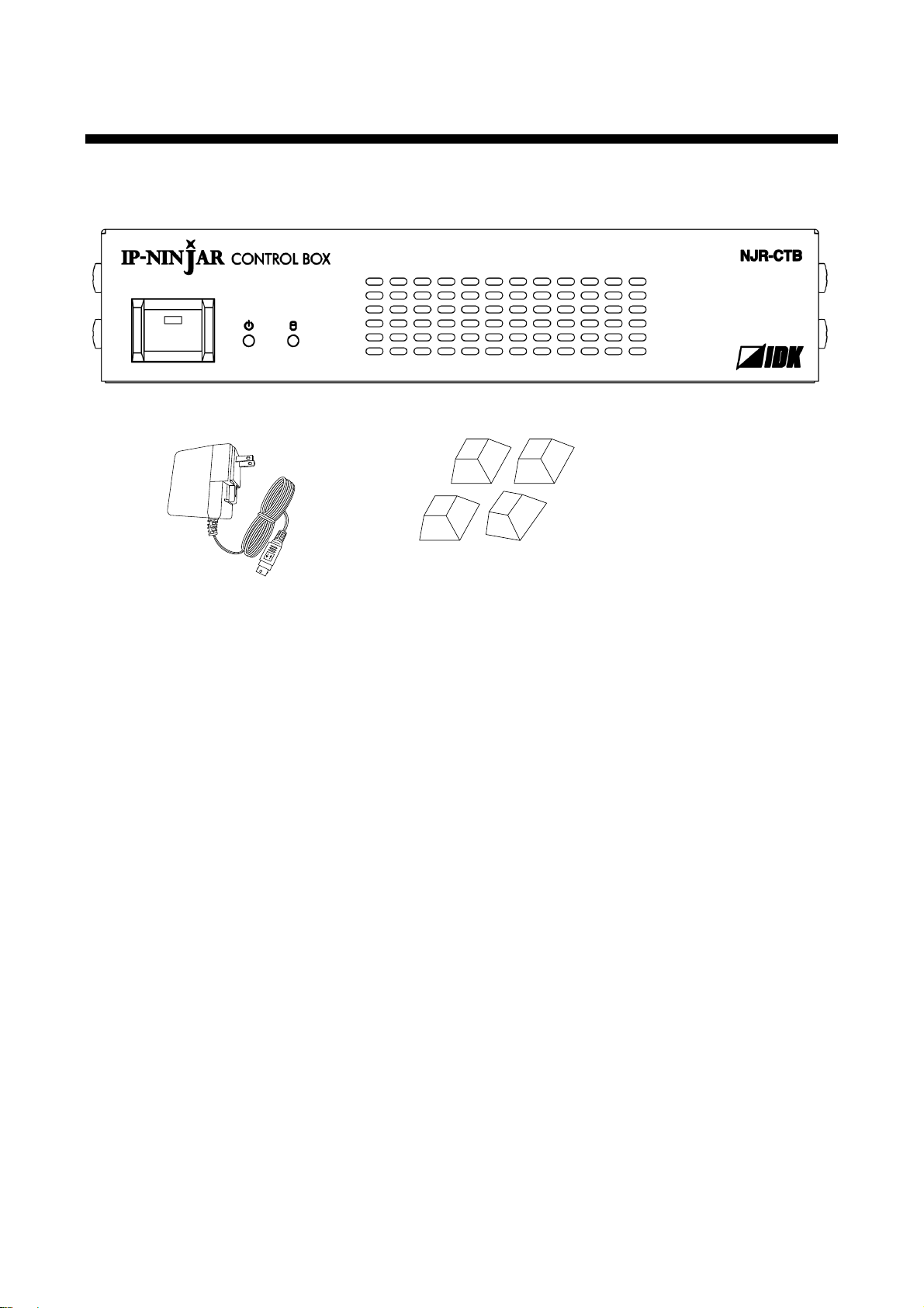
NJR-CTB (1)
DIN plug AC adapter with lock
(47.2 inch/1.2 m) (1)
Rubber feet (4)
2 Included items
Make sure all items below are included in the package.
If any items are missing or damaged, please contact IDK.
[Figure 2.1] Included items
10
NJR-CTB User’s Guide
NJR-T04HD
(Transmitter)
HDMI / DVI
98.4 ft./30 m
Blu-ray player
1080p
Blu-ray player
1080p
Blu-ray player
1080p
Blu-ray player
1080p
Multiple fiber OM3: up to 984 ft./300 m
Singlemode fiber OS1: up to 6.2 mile/10 km
Singlemode fiber OS1: up to 24.6 mile/40 km (optional extra)
4K-supported
monitor
HDMI / DVI
Up to 16.4 ft./5 m
IP network
PC for control
※
3
NJR-T01UHD
(Transmitter)
HDMI / DVI
Up to 16.4 ft./5 m
Control box (NJR-CTB)
Blu-ray player
NJR-R01UHD
(Receiver)
LAN
※
1
4K-supported
local monitor
HDMI / DVI
Up to 16.4 ft./5 m
10 GbE switch
4K@60
4K@60
4K@60
※1
The PC for control is connected to an NJR-CTB or NJR-T01UHD/NJR-R01UHD/
NJR-T04HD/NJR-R04 HD.
※2
③
LAN
※
1
The PC for control controls IP-NINJAR products.
※3
LAN
※
2
LAN
※
2
The NJR-CTB is connected to NJR-T01UHD/NJR-
R01UHD/NJR-T04HD/NJR-R04HD or 10 GbE switch.
NJR-R04HD
(Receiver)
1080p×4
Monitor
x4
HDMI / DVI
164 ft./50 m
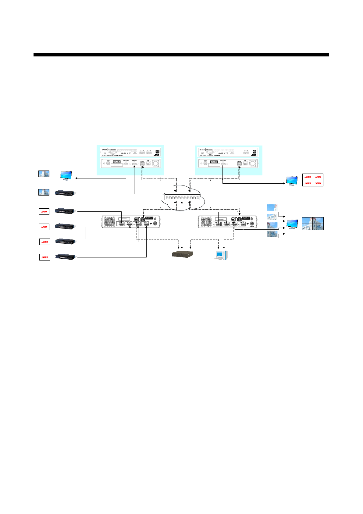
3 Product outline
The NJR-CTB is the control device to command comprehensively the NJR-01UHD and NJR-04HD. It allows
you to check connections and communications among products, switch video, control videowall, and so on
using WEB browser or external control devices via LAN.
The NJR-CTB enables extension, distribution, matrix switching, videowall, multiview using with IP-NINJAR
series transmitters, receivers, and a 10GbE switch. Additionally, the Web GUI allows you to set, manage and
control IP-NINJAR products that are connected to a network.
[Figure 3.1] Audio/Video over IP Network system diagram
Notes:
- Use the NJR-CTB with IP-NINJAR series products.
- The NJR-CTB cannot be connected to OPF series products of optical input/output slot boards of FDX series
products.
11

NJR-CTB User’s Guide
4 Features
■ Management
・ Automatically detecting IP-NINJAR series products on the network and displaying the list
・ Checking status of all connectet IP-NINJAR products through Web browser
・ Setting up connected IP-NINJAR products
・ Configuring Videowall and Multiview layout pattern by Web brower
・ Naming devices, registering groups
・ Registering display pattern preset
・ User administration management
■ Control input
・ WEB browser operation eliminates the need for software installation
・ Controlling from external devices using control commands
■ Control output
・ Sending control command to external devices
■ Other
・ AC adapter with locking mechanism
・ Virtual Matrix function
・ Supporting HTTPS
・ Logging device status and output to external device via API
・ Redanduncy, backup, and restore
12
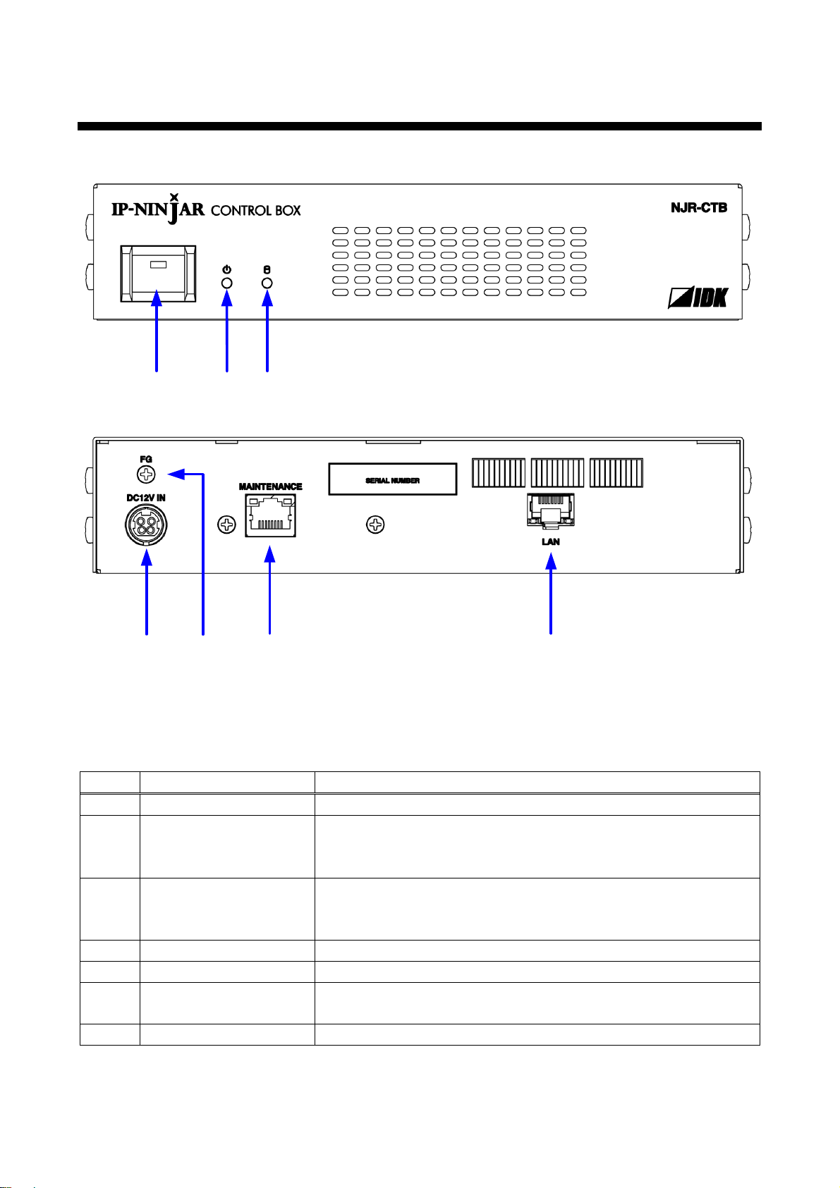
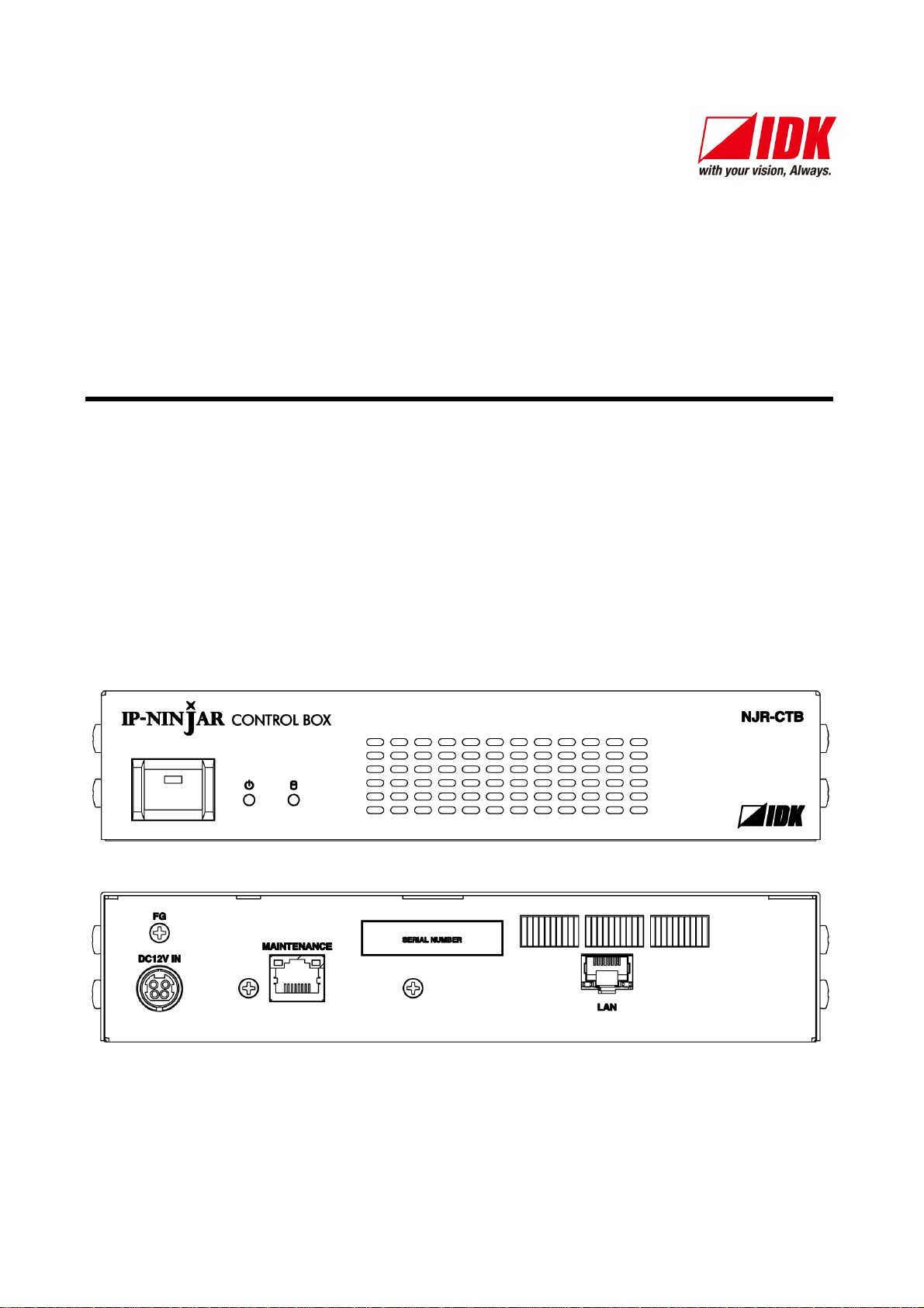
5 Panels
⑥
②① ③
⑤④
⑦
Number
Part name
Description
①
Power button
Powers on/off the NJR-CTB.
②
Power LED
Shows power status of the NJR-CTB.
Powered on: Lights in green.
Powered off: Does not light.
③
Access LED
Shows HDD disk access status
Being accessed: Lights in green.
No accessed: Does not light
④
Power supply connector
For the provided AC adapter.
⑤
FG (Frame ground)
For indoor ground terminal. M3 screws are used.
⑥
MAINTENANCE port
Connexts to the data network segmanet which is separated from the
IP-NINAJAR 10G network segment.
⑦
LAN port
Connects to IP-NINJAR 10G network segment.
NJR-CTB User’s Guide
[Figure 5.1] NJR-CTB drawing
[Table 5.1] Part name and description
13
NJR-CTB User’s Guide
NJR-T04HD
(Transmitter)
HDMI / DVI
Up to 16.4 ft./5 m
Blu-ray player
1080p
Blu-ray player
1080p
Blu-ray player
1080p
Blu-ray player
1080p
①
①
①
①
Multiple fiber OM3: up to 984 ft./300 m
Singlemode fiber OS1: up to 6.2 mile/10 km
Singlemode fiber OS1: up to 24.6 mile/40 km (optional extra)
4K-supported
monitor
HDMI / DVI
Up to 16.4 ft./5 m
IP network
PC for control*
3
NJR-T01UHD
(Transmitter)
HDMI / DVI
Up to 16.4 ft./5 m
Control box (NJR-CTB)
Blu-ray player
NJR-R01UHD
(Receiver)
LAN
*1
4K-supported
local monitor
Microphone
Mixer
Analog audio
Speakers
Power amplifier
Analog audio
10 GbE switch
4K@60
4K@60
4K@60
*1
The PC for control should be connecte d to NJR-CTB or N JRT01UHD/NJR-R01UHD/NJR-T04HD/NJR-R04HD.
*2
①
②
② ③
③
④
⑤
Speakers
Power amplifier
Analog audio
LAN
*1
The PC for control controls IP-NINJAR pr oducts.*3
LAN
*2
LAN
*2
NJR-CTB should be connected to NJR -T01UHD/NJR-
R01UHD/NJR-T04HD/NJR-R04HD or a 10GbE switch.
NJR-R04HD
(Receiver)
④
1080p×4
Monitor
x4
HDMI / DVI
164 ft./50 m
④
④
④
HDMI / DVI
Up to 16.4 ft./5 m
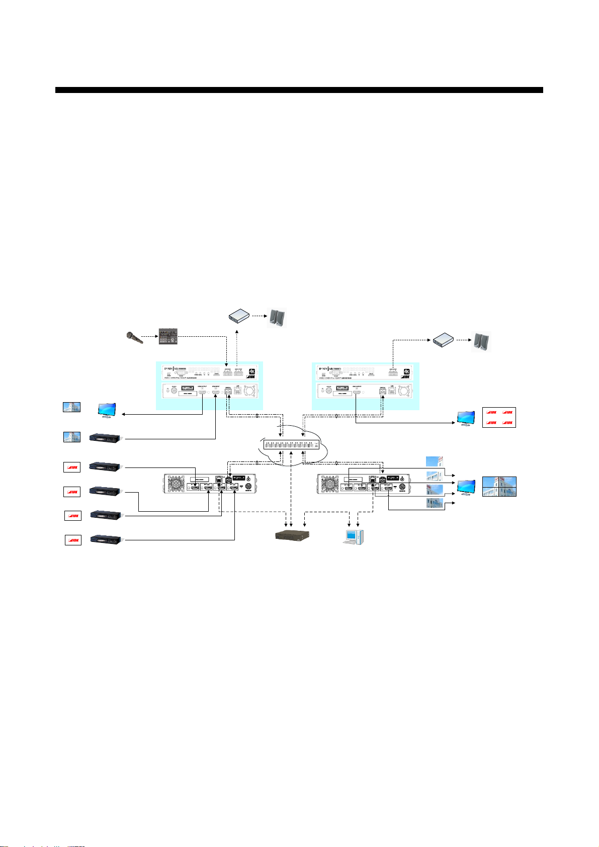
6 System configuration example
The NJR-CTB enables extension, distribution, matrix switching, videowall, multiview using with IP-NINJAR
series transmitters, receivers, and a 10GbE switch. Additionally, the Web GUI allows you to set, manage and
control IP-NINJAR products that are connected to a network.
① The Blu-ray player inputs video and audio signals to the HDMI input connector of the
NJR-T01UHD/NJR-T04HD.
② The NJR-T01UHD/NJR-T04HD sends these signals to the 10GbE switch over a fiber optic cable.
③ The 10GbE switch sends these signals to the selected NJR-R01UHD/NJR-R04HD or multiple
NJR-R01UHD/NJR-R04HD.
④ The NJR-R01UHD/NJR-R04HD outputs these received signals to monitors from its HDMI output
connector.
⑤ The analog audio output connector of the NJR-R01UHD outputs digital or analog audio of
NJR-T01UHD/NJR-T04HD.
14
[Figure 6.1] System configuration example

NJR-CTB User’s Guide
7 Preparations
Before using connecting the NJR-CTB, follow the precautions and instructions below.
7.1 Attaching Rubber feet
First, clean the bottom surface of the NJR-CTB as needed, and then peal the release papers from the rubber
feet and place them in each of the four corners.
7.2 Installation
Follow the instructions below when installing the NJR-CTB.
・ Do not place the NJR-CTB on another device directly.
・ Do not block vent holes. To provide adequate ventilation, maintain sufficient clearances around the
NJR-CTB (30 mm/1.18 inches or more).
・ Prepare ventilating equipment to keep the ambient temperature at 40 degrees C/104 degrees F or less. If
inadequately vented, the life of parts may be shortened and operation may be affected.
15

NJR-CTB User’s Guide
18
8-pin RJ-45 module
connector
Pin
number
Signal
MDI
MDI-X
1000BASE-T
100BASE-TX/10BASE-T
1000BASE-T
100BASE-TX/10BASE-T
1
TRX+ (Transmitted/Received
data+)
TX+ (Transmitted data+)
TRX+ (Transmitted/Received
data+)
RX+ (Received data+)
2
TRX- (Transmitted/Received
data-)
TX- (Transmitted data-)
TRX- (Transmitted/Received
data-)
RX- (Received data-)
3
TRX+ (Transmitted/Received
data+)
RX+ (Received data+)
TRX+ (Transmitted/Received
data+)
TX+ (Transmitted data+)
4
TRX+ (Transmitted/Received
data+)
N.C. (No Connection)
TRX+ (Transmitted/Received
data+)
N.C. (No Connection)
5
TRX- (Transmitted/Received
N.C. (No Connection)
TRX- (Transmitted/Received
N.C. (No Connection)
7.3 Cabling
Follow the precautions below when connecting NJR-CTB to an external devices.
・ Read the user’s guides of the external devices carefully.
・ When connecting a cable to the NJR-CTB or a compatible product, dissipate static electricity by touching
grounded metal such as racks before handling single cables. Failure to observe this precaution may
result in ESD (electrostatic discharge) damage.
・ Turn off all devices.
・ Be sure to fully seat all plugs and connections and dress cables to reduce stress on connectors.
7.3.1 Connecting LAN cable
The NJR-T01UHD and NJR-R01UHD send broadcast packets through the 10GbE LAN ports periodically for
the purposes of internal system management. If the 10GbE LAN port is connected to an existing network, it
may cause a broadcast storm* and may severely interfere with normal network operation. Contact IDK
before attempting to connect the 10GbE LAN ports of an IP-NINJAR system to any existing network
infrastructure.
*A broadcast storm occurs when a network is overwhelmed by continuous broadcast traffic resulting
in a network meltdown.
During installation, it is important to avoid the creation of network loops. Contact IDK if you require assistance
with network implementation.
7.3.1.1 MAINTENANCE / LAN port specification
LAN and MAINTENANCE port assignments are as follows.
Since Auto MDI / MDI-X that distinguishes and switches straight/cross cables automatically is supported,
extra care is not necessary to connect the NJR-CTB to PC, HUB or the like.
16
[Figure 7.1] LAN port
Physical layer
10Base-T (IEEE802.3i) / 100Base-TX (IEEE802.3u) /
1000Base-T (IEEE802.3ab)
Network layer
ARP, IP, ICMP
Transport layer
TCP
Port used for command control: 1100
Port used for WEB browser control (HTTP): 80
Application layer
HTTP
Your PC software
NJR-CTB
Connecting TCP-IP
→
(Occupying 1 port)
Sending command (@xxx)
→
← Replying command (@xxx)
Closing TCP-IP
→
(Releasing 1port)
data-)
data-)
6
TRX- (Transmitted/Received
data-)
RX- (Received data-)
TRX- (Transmitted/Received
data-)
TX- (Transmitted data-)
7
TRX+ (Transmitted/Received
data+)
N.C. (No Connection)
TRX+ (Transmitted/Received
data+)
N.C. (No Connection)
8
TRX- (Transmitted/Received
data-)
N.C. (No Connection)
TRX- (Transmitted/Received
data-)
N.C. (No Connection)
7.3.1.2 MAINTENANCE / LAN communication specification
[Table 7.1] LAN communication
NJR-CTB User’s Guide
Note: Up to 8 connections can be used simultaneously for command control.
7.3.1.3 Limit on the number of TCP-IP connections and port overload management
The NJR-CTB’s maintenance port supports a maximum of eight simultaneous connections (eight logical
ports). To maintain optimal system accessibility, it is advisable to issue “port-open” and “port-close”
commands before and after command or query strings are issued. This approach enables eight or more
control devices to be effectively interfaced simultaneously and without concern for communication errors. As a
safeguard, the NJR-CTB incorporates a 30-second timeout window for each port. If any port is inactive for
more than 30 seconds, it will be closed automatically.
[Table 7.2] Increasing connections
Note:
If no command is sent from the PC side to the NJR-CTB for 30 seconds, the NJR-CTB automatically
disconnects from that device.
17
 Loading...