

Page 1
VQE1
E1 over RF/Ethernet Multiplexer
V 1.3
User’s Manual
IP-NET, LLC
contents -1-
Page 2

VQE1
E1 over RF/Ethernet Multiplexer
User’s Manual
IP-NET, LLC.
2008.2
contents -2-
Page 3

Disclaimer
The information contained in this document is subject to change without notice
and does not represent a commitment on the part of IP-NET, LLC. The information
in this document is believed to be accurate and reliable; however, IP-NET assumes
no responsibility or liability for any errors or inaccuracies that may appear in the
document.
Copyright© 2008 by IP-NET, LLC. All rights reserved. No part of this publication may
be reproduced or distributed in any form or by any means, without prior written
permission of IP-NET.
Product Model: VEQ1
Product Name: VQE1 Virtual Quad E-1 over RF/Ethernet Multiplexer
Manual Version: 1.3
Last Update: 2008. 2
IP-NET, LLC.
Address: 10256 N.W. 47
Sunrise, Florida 33351
U.S.A.
Tel: (954)-5878-5929 / (954)-578-5930
Fax: (954)-212-9205
Web: www.hfcnet.net
E-mail: info@hfcnet.net
th
Street,
, sales@hfcnet.net
contents -3-
Page 4

TABLE OF CONTENTS
1. GENERAL....................................................................................................................... 1
1.1 OVERVIEW ........................................................................................................................ 1
1.2 F
EATURES.......................................................................................................................... 1
1.3 APPLICATIONS .................................................................................................................. 2
1.4 T
IMING MODES ................................................................................................................. 3
2. SYSTEM ARCHITECTURE ..................................................................................... 5
2.1 BLOCK DIAGRAM............................................................................................................... 5
2.2 DESCRIPTION.................................................................................................................... 5
2.3 FRONT PANEL .................................................................................................................... 5
2.3.1 Diagram.................................................................................................................. 5
2.3.2 LEDs......................................................................................................................... 6
2.3.3 Dip switch.............................................................................................................. 6
2.4 REAR PANEL ...................................................................................................................... 6
2.4.1 Grounding screw................................................................................................. 6
2.4.2 System alarm....................................................................................................... 6
2.4.3 E1 Port.................................................................................................................... 7
2.4.4 Ethernet ports...................................................................................................... 7
2.4.5 Power ...................................................................................................................... 7
3. INSTALLATION ......................................................................................................... 7
3.1 MECHANICAL..................................................................................................................... 7
3.2 ELECTRICAL ...................................................................................................................... 8
3.2.1 Power connection............................................................................................... 8
3.2.2 E1 connections .................................................................................................... 8
3.2.3 DOCSIS or Ethernet connection................................................................... 9
4. OPERATION............................................................................................................... 10
4.1 LED DEFINITION............................................................................................................ 10
4.2 L
OOP BACK CONTROL ..................................................................................................... 11
4.3 DIP SWITCHES DEFINITION .......................................................................................... 11
5.
COMMON FAULTS .................................................................................................. 12
5.1 E1
ALARMS...................................................................................................................... 12
5.2 LNK/ACT LED OFF ......................................................................................................... 12
5.3 READY LED DOES NOT BLINK ....................................................................................... 13
5.4 C
ANNOT SET UP E1 CHANNEL ....................................................................................... 13
5.4.1 Same LAN domain............................................................................................ 13
5.4.2 Different LAN domain ..................................................................................... 13
5.5 DOWNSTREAM REPORTING SLIPS .................................................................................. 13
6. WEB MANAGER ....................................................................................................... 13
6.1 SHOW CURRENT STATUS MENU ..................................................................................... 13
6.2 L
INE TEST ....................................................................................................................... 15
contents -4-
Page 5

6.3 CONFIGURATION............................................................................................................. 16
7. SPECIFICATION...................................................................................................... 21
7.1 C
7.2 DOCSIS
APACITY ........................................................................................................................ 21
RF INTERFACE............................................................................................... 21
7.3 E1 INTERFACE ................................................................................................................ 21
7.4 10/100BASE-T PORT ................................................................................................... 21
7.5 POWER ............................................................................................................................21
7.6 OPERATING CONDITION ................................................................................................. 21
7.7 DIMENSIONS................................................................................................................... 21
7.8 WEIGHT........................................................................................................................... 21
contents -5-
Page 6

IP-NET, LLC
1.
General
1.1 Overview
Thank you for selecting the VQE1 product designed and made by IP-NET, LLC. The product
can be used to provide E1 communication channels over DOCSIS 1.0, 1.1, or 2.0 and/or directly
over Ethernet/IP networks.
The VQE1 has many optional parameters, which can be modified by the user to suite
different application requirements. Please read this manual carefully before installing the
product.
It is well known that the E1 signal comes from PCM technology which is TDM in nature. It
transmits information in a constant bit rate of E1_2048kbit/s, T1_1544 kbit/s(future). TDM
technology occupies fixed transmission bandwidth, with QoS features suitable for real-time
applications such as voice and video. The QoS features include short and stable transmission
delay, low jitter and wander, etc.
On the other hand, Ethernet is based on statistical multiplexing, transmitting and exchanging
information in packets. It does not take up a fixed transmission bandwidth, which is good for
achieving higher bandwidth utilization. But Ethernet technology does not provide adequate QoS
for many real time applications.
Until recently, voice and data were, and still are to a large extent, transported over two
separate networks. But the requirement for both types of information to be carried over unified
networks is growing rapidly. Techniques to integrate data Packets over SONET/SDH into TDM
networks have been around for many years. But for voice over packet based data networks,
most of the efforts are spent on creating special equipment that packetizes voice or video
signals, such as VoIP techniques.
However, to take advantage of the data network, it is neither cost effective, nor necessary to
hastily replace all the TDM based legacy equipment with new packet based equipment. The VQE1
can be used to emulate transparent E1 channels over a DOCSIS or Ethernet network with
adequate QoS, so that most of the existing E1-based applications can be readily setup over
Ethernet LANs and WANs.
1.2 Features
z User-friendly Web server supported for easy setup and maintenance
z Point to point and point to multipoint supported
z Uplink ports 1+1 backup supported
z Four E1 Ports supported, E1 or T1 (future) easy selected by Web Manager
z Stable E1 clock recovery, low jitter and wander
z Low processing delay for E1 channels, high bandwidth usage efficiency
z Resistant to packet loss, with PCM frame synchronization protection
z User definable encapsulation packet size for different application
z Enough jitter buffer to resist packet delay variation (PDV)
z Local Ethernet port throughput limiting, assuring E1 QoS
z Local and remote E1 LOS and AIS and packet loss indication for trouble-shooting and
maintenance
z Supports cascaded concatenation or Daisy-Chaining for more than 4 E1 ports
VQE1 User Manual V1.3 -1-
Page 7
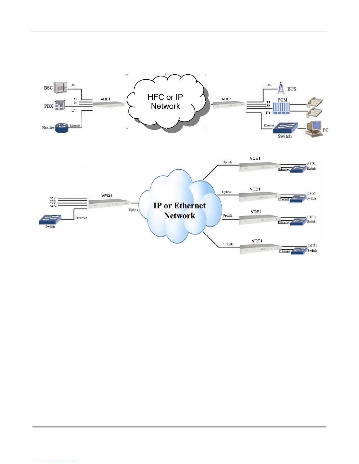
1.3 Applications
VQE1 is used to setup 1~4 clear E1 channels over LAN or IP networks, as depicted
in Fig. 1.3-1.
IP-NET, LLC
(a) Point to Point Application
(b) Point to Multipoint Application
Fig. 1.3-1 VQE1 application paradigm
In the figure, a pair of VQE1’s create clear E1 channels over a DOCSIS packet
network, providing connections between a PBX and a telephone exchange, or other
terminal devices. At the same time, computers talk to each other through the local
Ethernet ports on the VQE1’s. This configuration guarantees that the E1 channels get
higher priority over computer data for maximum QoS.
In addition to robust data and E1 transmissions over DOCSIS or Ethernet networks,
the VQE1s can also be configured to work with wireless bridges. One common application
of VQE1 is to set up point to point wireless E1 links using low cost wireless LAN bridges
or IP-NET WIRELESS CAPs. VQE1 can work with most LAN bridges on the market. It may
be necessary to adjust different parameters such as packet size and packet jitter
absorption buffer size for best operation for different LAN bridges.
Be aware that wireless LAN bridges may have a very limited bandwidth. If Ethernet
data is to be transferred at the same time, the traffic must be restricted. Otherwise it will
affect the E1 packets. Since the LAN bridges usually don’t have adequate QoS
mechanism to guarantee the E1 priority, it is strongly recommended that the data traffic
be routed through the VQE1 local data port, as depicted in Fig. 1.3-2.
VQE1 User Manual V1.3 -2-
Page 8

IP-NET, LLC
Fig. 1.3-2 Preferred connections for LAN traffic
WARNING: When connecting to a wireless LAN bridge, the uplink Ethernet
cable often connects to the outdoor unit, posing danger to lightning strikes that
can seriously damage the equipment. To protect the equipment as well as
people, surge protection devices with good earth connection is strongly
recommended. Poor earth connection may also hinder the operation of the
Ethernet port, causing severe packet losses.
1.4 Timing modes
To emulate a clear E1 channel over a packet network, the VQE1 not only conveys data
stream content correctly from the source to the destination, but also passes timing.
Packet networks do not provide such built-in timing transparency mechanism as TDM
networks do. VQE1 uses a proprietary algorithm to reconstruct the E1 clock at the
destination. The recovered clock is of very high quality, with low jitter and wander.
Typical frequency offset is within ±5ppm, and jitter is below 0.1UI. It can be adapted in
most applications. This timing mode of rebuilding the E1 clock at the destination is called
Adaptive Timing
.
For applications where separate clock distribution network exists, another timing
mode, Loop back Timing,
may be used for maximum clock quality.
The two timing modes of VQE1 are depicted in Fig.1.4-1.
Fig.1.4-1 E1 Timing modes
VQE1 User Manual V1.3 -3-
Page 9

Q
Q
IP-NET, LLC
Correct timing mode setting is important for smooth operations. In most cases,
setting both units to adaptive timing mode is sufficient. But sometimes, setting one unit
to loop timing mode may work better. For example, setting the VQE1 unit connected with
the clock master (such as local exchange) to loop back mode, and the other unit
connected with the clock slave (such as PBX or remote module) to adaptive mode, is
probably better than setting both to adaptive modes.
One typical error in telecom applications is to connect two communication devices
that are both clock slaves. Neither VQE1 will support such operation no mater how the
timing modes are set.
Note:
that the E1channel emulation takes several minutes to stabilize.
During that period, clock drift may exceed the limit, errors and slips may occur.
Various timing schemes are enlisted in Table 1.4-1, for applications depicted in
Fig.1.4-2.
Equipment
A
A side
V
E1
RF or
10/100 Base T
DOCSIS
or Packet
Network
RF or
10/100 Base T
B side
V
E1
Equipment
B
Fig.1.4-2 Timing mode scheme reference diagram
Table 1.4-1 Timing mode schemes
Equipment
A clock
mode
Equipment
B clock
mode
master master
A side
EthMux V4
Timing
mode
loop back loop back
adaptive adaptive
master master adaptive adaptive
master slave
slave master
loop back adaptive
adaptive adaptive
adaptive loop back
adaptive adaptive
slave slave Not allowed
Note that setting both units to adaptive timing mode works well for all the conditions,
although the other option may work better.
B side
EthMux V4
Timing
mode
Note
Equipment A & B
clocks synchronous
Equipment A & B
clocks
plesiochronous
VQE1 User Manual V1.3 -4-
Page 10

IP-NET, LLC
2.
System architecture
2.1 Block diagram
The internal functional structure of VQE1 is depicted below:
Fig. 2.1-1 Functional diagram
RF
Modem
2.2 Description
The heart of VQE1 is the TDM/Packet processing unit. It truncates E1 data stream,
putting the data into Ethernet packet with or without IP headers. The packets are
passed to the Ethernet switch unit via MII interface, and are sent out adaptive through
the uplink port to the WAN port of the RF MODEM module for transmission via a DOCSIS
network, or through a Daisy-Chain up to another VQE1. Ethernet data from two local
data port are also sent out through the uplink ports, but with lower priority than those
packets containing E1 data.
In the reverse direction, packets from the RF MODEM or the uplink ports are sorted
at the switch unit. All but E1 packets are passed to the local data ports. The packets
containing E1 data are sent to the TDM/Packet processing unit for reassembly of the
original data stream, and recovery of the E1 clock which is the key element of the
device. A very sophisticated algorithm is used to ensure that the reconstructed clock will
meet the stringent requirement of TDM applications. The most important parameters
are jitter, wander, and signal delay.
The control unit interfaces with the user through a console port so that various
operational parameters can be modified.
2.3 Front panel
2.3.1 Diagram
Main Status
Far-End Status
DIP Switch E1 Alarm Status Ethernet Status Cable Modem Status
VQE1 is shown in Fig. 2.3.1-1.
Fig. 2.3.1-1 Front panel of VQE1
VQE1 User Manual V1.3 -5-
Page 11

IP-NET, LLC
2.3.2 LEDs
There are 31 LEDs on the front panel, divided into 5 groups. For detailed LED
description, refer to The Table 4.1-1. To verify operation, the LEDs should be interpreted
in the following sequence:
In the STATUS group, the PWR and READY green LEDs indicate the operation status
of the device.
In the CABLE group, there are five red, yellow and green LEDs which indicate the
condition of the DOCSIS cable modem module.
In the 10/100 BASE-T group, the 12 Ethernet status green LEDs indicate the status
of the 4 Ethernet ports.
In the E1/T1 ALARM group, eight red LEDs are provided for alarm indication, 4 for
the local and remote E1 ports, and 4 for packet alarms.
In the FAR-END UP Group Four LEDs indicate the status of far-end E1 uplink. These
LEDs are also green.
For detailed LED description, refer to The Table 4.1-1.
2.3.3 Dip switch
There are two Dip Switches on the front panel; the definitions are shown on Table
4.3-1.
2.4 Rear panel
The VQE1 has power supply options for 110-220VAC and -48VDC. The rear panel is
depicted in Fig. 2.4-1.
DC power with 2X2P socket
Fig. 2.4-1 Rear panel
2.4.1 Grounding screw
This is used to connect the chassis to the protective ground.
2.4.2 System alarm
The VQE1 can output system alarms for maintenance purposes. There are 2 alarm
output pins, the Prompt Alarm and the Deferred Alarm, as shown in Fig. 2.4-2.
VQE1 User Manual V1.3 -6-
Page 12

SYS ALARM
IP-NET, LLC
D P
Prompt AlarmDeferred Alarm
Fig. 2.4-2 System alarm port
The alarm conditions for each alarm output are set by the user. The output ports
float when no alarm is present, and connect to ground when alarm activates.
2.4.3 E1 Port
There are 4 E1 ports on the rear panel. The E1 ports impedance are E1-120Ω for
twisted pair cables or 75Ω for coax. The E1-120Ω RJ45 sockets are internally set by
default to 120Ω ports.
2.4.4 Ethernet ports
There are four RJ45 Ethernet ports on the rear panel, 2 for uplink connection to the
DOCSIS packet network and 2 local data ports for local computers to access the uplink.
Uplink ports support 1+1 backup.
The Web manager is supported through anyone of the two local data ports.
2.4.5 Power
Three power options are available, two via 100-240VAC 50/60 Hz and another via -
48VDC. The power source is selected via a rear panel three position rocker switch.
3.
Installation
3.1 Mechanical
VQE1 can be placed on a table top or mounted in a 19” rack. If it is to be mounted
in a rack, the four (4) 10mm-high stands should be removed with a screw driver.
The mechanical dimensions of VQE1 are given in Fig.3.1-1.
VQE1 User Manual V1.3 -7-
Page 13

IP-NET, LLC
Fig.3.1-1 Mechanical dimensions
3.2 Electrical
3.2.1 Power connection
The VQE1 consumes less than 15W of power.
The VQE1 offers the broadest powering facilities via a standard -48 VDC, 110 VAC or
220 VAC Universal Power Supply. For the -48V type, connect -48 supply to the power
connector -48V port, and ground the other port. The screws on the power connector
must be tightly fastened. For 110 or 220V equipment, connect the device to the 110220V outlet with standard power cord supplied with the equipment. Please specify
power cord required when ordering.
Note that there is a 1A fuse in the VAC power cord socket which may be replaced
when burned. The -48V equipment uses PPTC resettable fuse, no customer
replacement is required.
It is recommended to turn off the power switch before connecting or disconnecting
the power.
On the left corner of the rear panel, a screw is provided for connecting the chassis to
the protective ground. Be sure to make this connection using a thick wire.
WARNING: The system must be securely connected to a good protective
ground for safety. All interconnected equipment must be grounded for
maintaining signal integrity as well. Ground potential differences may also
damage the interface ports.
WARNING:
ground.
To avoid electric shock, the 110-220V outlet must have good
3.2.2 E1 connections
The E1 ports on VQE1 are used for connecting to E1 equipment such as telephone
exchanges or PCM terminals.
Four E1 Ports are supported. The E1s are easily selected by Web Manager
E1 ports impedance are E1-120Ω for twisted pair cables or 75Ω for coax. The E1-
120Ω RJ45 sockets impedance is set by internal jumpers to default to 120 Ω for
all ports.
VQE1 User Manual V1.3 -8-
Page 14

IP-NET, LLC
The E1-120Ω connection cable is made with RJ45 connectors and a length of 4-pair
twisted cable. The cable is not provided with the equipment, and the user is responsible
for making such cables in the field with length suitable for a particular installation. The
signal definition is given in Table 3.2.2-1, and pin order is depicted in Fig. 3.2.2-1. Note
that pin-1 and pin-2 should use the same twisted pair, so should pin-4 and pin-5.
1
8
Fig. 3.2.2-1 RJ45 pin order
Table 3.2.2-1 120Ω-E1 signal definition
Pin 1 2 3 4 5 6 7 8
Signal
- + + -
E1-IN
GND
E1-OUT
GND
The RJ45 sockets are default for E1-120Ω/T1-110Ω, the 4-jumpers of CNM26,
CNM25, CNM24, CNM20 in the VQE1 main board are jumpered between pins 1-2.
The cable No. BH4.851.122 is for one RJ45 connector to two BNC (F) sockets
conversion cable for 75 Ω E1 operations. The 4-jumpers of CNM26, CNM25, CNM24, and
CNM20 in the main board of the VQE1 board are jumpered 2-3. This cable is optional.
3.2.3 DOCSIS or Ethernet connection
Connect the Uplink 1 or 2 Ethernet port to the WAN port for connection via a DOCSIS
transport network, or to external modems such as the wireless LAN bridge or Ethernet
networks for other WAN transport solutions. Connect the local data port to computers or
to an Ethernet switch for local data applications.
The signal definition of the two local Ethernet ports is given in Table 3.2.3-1.
Table 3.2.3-1 Ethernet signal definition
Pin 1 2 3 4 5 6 7 8
Signal RxD+ RxD- TxD+ TxD-
Note: The ports confirm to HP auto-MDIX spec. It will automatically adapt
to parallel or crossed cables.
The signal definition of the uplink Ethernet ports is given in Table 3.2.3-2.
Table 3.2.3-2 Ethernet signal definition
Pin 1 2 3 4 5 6 7 8
Signal RxD+ RxD- TxD+ GND GND TxD- GND GND
VQE1 User Manual V1.3 -9-
Page 15

IP-NET, LLC
Note: The uplink port link parallel cable to LAN Bridge.
WARNING: When connecting to a wireless LAN bridge, the uplink Ethernet
cable often connects to the outdoor unit, posing danger to lightning strikes that
can seriously damage the equipment. To protect the equipment as well as
people, surge protection devices with good earth connection are strongly
recommended. Poor earth connection may also hinder the operation of the
Ethernet port, causing severe packet losses.
4.
Operation
After successful installation, switch on power. The operation status can be monitored
with LEDs on the front panel. Do not use a loop back cable to suppress unused E1 port
alarms, because that shows the E1 is in operation, and will take up about 2 Mbps
bandwidth. If the uplink channel does not have enough bandwidth, this will affect
packets for the working E1.
Various operational parameters can be set or modified through Web manager.
It is often helpful to use an E1 tester to check the quality of the E1 channels, by
measuring the round trip bit error rate of the channel. The loop back control in Web
manager is useful for this purpose.
4.1 LED Definition
There are 31 LEDs on the front panel, the definitions of LED conditions are as follows:
Table 4.1-1 LED Definition
LED Color Definition Explanation
CABLE
On: Normal
CM R Cable Modem
DS G DownStream RF
US G UpStream RF
DOCSIS Connection
CON Y
DATA R WAN Data Flow
Registered
Off: Power Off / Failure
Blinking: Scanning Downstream for QAM
On: Downstream RF Acquired and Ready
Blinking: Modem Module transmitting to
CMTS and obtaining parameters
On: RF Path Ready
Blinking: Registration In Progress
On: Registration Ready
On: System Ready via Ethernet
Connection to E1 module
Off: Failure of Ethernet Connection to E1
module
Blinking: Normal operation during E-1
and data TX/RX
VQE1 User Manual V1.3 -10-
Page 16

IP-NET, LLC
STATUS
PWR G power indicator
READY G operation status
10/100Base-T
SPD G speed indicator
LKA G link activity indicator
FDX G duplex indicator
E1/T1 ALARM
LOS
1~4
LOS indicator for 4 E1
R
ports respectively
(Local: RA is off.
Remote: RA is on.)
On: Normal
Off: Power Off / Failure
On or off: System abnormal or system
initialization.
Blink: Normal operation
On: 100M
Off: 10M
On: Link
Blink: Data
Off: Inactive
On: Full duplex
Off: Half duplex
On: LOS
Off: Normal or disable
Blink: AIS
PKL
1~4
R packet loss indicator
On: Ethernet packet loss
Off: Normal
Blink: E1 Packet Loss
FAR-END UP
Far-end
UP
n=1~4
communication status
(Number of remote
G
different MACs
connected with local.
Slave mode n=1,
packet
On: Normal, Remote MAC attained
Off: Remote MAC unattained while ARP is
activated or disable
master mode n=2~4,
at local end)
4.2 Loop back control
The loop back of E1 ports control are supported in Web manager, shown in section
6.2.
4.3 Dip Switches Definition
There are Dip Switches on the front panel, the definition is as follows.
VQE1 User Manual V1.3 -11-
Page 17

IP-NET, LLC
Table 4.3-1 Dip Switches Definition
2-Dip Switch ON OFF
RA
MATN Default IP address
4 red LEDs indicate
remote
E1 LOS state
4 red LEDs indicate
local E1 LOS state
User setting IP
address
5.
installation and maintenance. Please seek support from IP-NET, LLC for other problems.
Common faults
This paragraph describes common mistakes and faults that may occur during
5.1 E1 Alarms
There are two groups of LEDs, 4 LEDs E1 PKT LOS and 4 LEDs E1 LOS for E1 alarms
LEDs.
When E1 LOS LED is on, loss of E1 signal fault is detected by VQE1. Possible causes
include:
z The downstream equipment such as telephone exchange or PCM terminal is
powered off.
z The E1 cable connection is loose or broken.
E1 LOS LED blinks when respective input E1 signal is AIS, i.e. the content of E1 data
is all 1’s. Such alarm indicates fault conditions on the part of the downstream equipment.
E1 LOS site is controlled by Dip Switch RA state. When RA Dip Switch ON, the 4 red
LEDs indicate remote
E1 LOS state.
local
The 4 LEDs, E1 PKT LOS are packet loss indicator, On for Ethernet packet loss, Blink
for E1 Packet Loss, Off for Normal.
5.2 Lnk/Act LED off
Lnk/Act LED off means the corresponding Ethernet link is not working. Check the
Ethernet cable connection, and the status of the device on the other end of the cable.
E1 LOS state. When RA Dip Switch OFF, the 4 red LEDs indicate
VQE1 User Manual V1.3 -12-
Page 18

IP-NET, LLC
5.3 Ready LED does not blink
After the unit is powered on, the Ready LED should start to blink. If it does not, try
switching power off and on again. If this error persists, call for support.
5.4 Cannot set up E1 channel
5.4.1 Same LAN domain
When two VQE1s are within the same DOCSIS / Ethernet broadcast domain, try
following.
Check if the transmission network is on.
Check that the network will pass broadcast packets. For a network that suppresses
broadcast packets, as some of the wireless LAN bridges do, disable ARP and manually
setup local and remote MACs.
Check that there is no MAC address conflict on the LAN.
Check that the transmission network has enough bandwidth (more than 2.5Mbps
duplex).
5.4.2 Different LAN domain
When two VQE1s are in different DOCSIS Ethernet broadcast domains, IP headers
must be used, and packets will be routed by a gateway router, try the following.
Check if the default gateway IP is defined correctly.
Check if the local and remote IP is set correctly.
Check for any conflicts in IP or MAC addresses.
Make sure the transmission network has enough bandwidth.
5.5 Downstream reporting slips
Check if the downstream equipment has correct clock mode. At least one of them
must be clock master. Set the VQE1 on master side to loop back timing.
If the downstream equipment on both sides is not synchronized, slips are not
avoidable.
At the transition time after power on or reapplying the E1signal, slips and errors are
acceptable. Such transition may take several minutes.
6.
Web Manager
Web manager supported through anyone of two user data ports.
6.1 Show current status menu
Any local DATA interface of VQE1 supports Web Server management. The
management has three sections: Status, Line Test and Configuration. User name and
password are needed to enter the sections of Line Test and Configuration. Both the
default user name and password are “root” .Customers can modify the user name and
password in the configuration section. Note that the modifications of Configuration
will be valid after submit and reboot, while the modifications of Line Test (E1
loop-back setting) can be valid only after submit.
After inputting the IP address, status information of VQE1 will be displayed such as
hardware version, software version, IP address, subnet mask, gateway address and MAC
address. The default IP address is 192.168.1.2. Details are shown in fig. 6.1-1.
VQE1 User Manual V1.3 -13-
Page 19

IP-NET, LLC
Fig.6.1-1 Status Menu
Click on the E1 Status option will bring the E1 Status Information window showing
LOS, AIS and loop-back status.Fig.5.1-2.
Fig.6.1-2 E1 Status Information
VQE1 User Manual V1.3 -14-
Page 20

IP-NET, LLC
6.2 Line Test
Loop back controls provide E1 line loop test function.
The meaning of LLop (Rx-->Tx) and RLop (Tx-->Rx) is depicted in Fig. 6.2-1.
Four E1 ports can set separately by click “
” icon.
Fig. 6.2-1 Loop back definition
Clicking on E1 Loopback option will bring the window shown as fig. 6.2-2. E1 setting
can be valid after submitting but not saved, that is, four E1s will not loop back after
restart.
Fig.6.2-2 E1 Loop-back Management
VQE1 User Manual V1.3 -15-
Page 21

IP-NET, LLC
6.3 Configuration
This section includes Network Management, E1 Management, Change Password,
Default Parameter and Reboot. All the settings and parameters will be valid after reboot.
Fig.6.3-1 Network Management
Fig.6.3-2 E1 management
VQE1 User Manual V1.3 -16-
Page 22

Parameter Item Specification
Network
Management
E1
Management
IP-NET, LLC
Table 6.3-1 Main Parameter of VQE1
IP Address
Default IP address 192.168.1.2
Make calculation for source IP
address and submask, and
destination IP address and submask
respectively. If identical result can be
Submask
got, the source and destination are in
the same subnet. Otherwise, they are
in different subnet and the
connection should go through
gateway.
Default :255.255.255.0
If the source and destination are in
Gateway IP
Address
different subnet, gateway IP address
should be set.
Default:192.168.1.1
E1
E1
T1
Options are for four E1
Default E1
E1 data size,
N=1~5,corresponding to
256×Nbyte(E1)、192×Nbyte(T1).
Encapsulation
Level
1~5
The bigger the packet is ,the more
data is encapsulated in each packet,
and the lower overhead it has.
Bandwidth efficiency will be raised
and delay will be increased.
Yes
Default :2
Yes:IP encapsulation,source and
destination IP address should be
Use IP
Encapsulation
No
set. Bandwidth efficiency will be
reduced
(default)No:do not use IP
encapsulation,high bandwidth
efficiency
Customers can define IP service
IP TOS
type,
Default 0x 00
Set full duplex bandwidth for uplink
Uplink
Bandwidth
Ethernet port,actual bandwidth
should be higher than this value.
Default 10000Kbps
Remote end IP address;4 E1 line IP
Destination IP
addresses can be set separately
Default 192.168.1.3
VQE1 User Manual V1.3 -17-
Page 23

IP-NET, LLC
Parameter Item Specification
Timing Mode
Jitter Buffer
Adap
tive
Loop
back
4~12
0ms
Default :E1timing from remote E1
stream;
E1 timing comes from local E1
stream
Coming packets buffer to eliminate
jitter. Range:4~120ms。
Default 16ms
Yes:with VLAN label,support the
Enable VLAN
VLAN network with priority to
guarantee E1 QoS;
(default)No:no VLAN label
Add 4 byte before Ethernet frame
when VLAN is enable. First two bytes
VLAN ID
are 0x8100,and second two bytes
are VLAN ID,which can be set by
customer.
Note:
1.- The actual output rate should correspond to the transmission bandwidth. If the
transmission bandwidth is smaller than actual uplink rate, E1 errors will occur. So we set
the maximum bandwidth of uplink line. When the uplink is higher than actual E1 rate,
the difference value is Ethernet access rate. When the uplink is lower than actual E1 rate,
the Ethernet rate is 0.
For example:the transmission line can provide 6M bi-direction bandwidth. If we use
two E1 channels, the local uplink should be set smaller than 6M.If not, the actual rate
may be higher than the transmission bandwidth. E1 errors may occur.
2.- Bandwidth auto adaptation for E1 depends on the connection of E1. If there is
no signal loss for E1, system will allocate bandwidth for it. When E1 port is free,
bandwidth will be released ,which can be used for local Ethernet access.
3.- The MAC address of VQE1 is fixed in the device. ARP is supported and the remote
end MAC address can be obtained through auto-negotiation. So it is unnecessary to set
the MAC address for the remote end, but IP address is needed.
NOTE:Each device should have only one MAC address in the multicast
area!
VQE1 User Manual V1.3 -18-
Page 24

IP-NET, LLC
Click in on the Change Password option will bring the widows as follows:
Fig.6.3-3 Change Password
Fig.6.3-4 Default parameter recovery
VQE1 User Manual V1.3 -19-
Page 25

IP-NET, LLC
Fig.6.3-5 Restart operation
Clicking on “confirm” will make all the parameters valid.
VQE1 User Manual V1.3 -20-
Page 26

IP-NET, LLC
7.
Specification
7.1 Capacity
The VQE1 supports four E1 ports, two 10/100Base-T uplink Ethernet ports and two
10/100Base-T local data Ethernet ports.
7.2 DOCSIS RF Interface
DOCSIS 1.0, 1.1, 2.0 compatible
Please see DOCSIS Specs and IP-NET Corporate Services DOCSIS ANNEX
7.3 E1 interface
Complies with ITU-T G.703 recommendation
Four E1 Ports Supported. E1 or T1 (future) easily selected by Web Manager
E1 port impedance E1-120Ω for twisted pair cables or 75Ω for coax (The RJ45 E1-
120Ω are default for all ports)
End-to-end delay (minimum delay setting) ≤ 5ms
Output frequency offset (adaptive timing, stabilized) ≤5 ppm
Output jitter (adaptive timing) ≤ 0.1UI
7.4 10/100Base-T port
Complies with IEEE 802.3 - 10M/100M Adaptive
Half/Full Duplex Adaptive
Support 802.1Q MAC
Uplink ports 1+1 backup supported
Two user data ports supported. And Web manager supported through anyone of two
user data ports.
7.5 Power
AC: 165V~265V/50Hz or
DC: -38V ~ -62V (optional) or dual power supply
Power Consumption: ≤15W
7.6 Operating condition
Temperature: (0~50) °C
Humidity: ≤90% (non-condensing)
7.7 Dimensions
Width × Height × Depth: 440 × 44 × 231 mm
7.8 Weight
2.5 kg (5.5 lbs.)
VQE1 User Manual V1.3 -21-
 Loading...