

IPMobileNet IP Series, M64450G25 Product Owners Manual

P
IIP
Seerriieess
S
M6644445500
M
Hiigghh SSppeeeedd
H
O
PPrroodduucctt O
Date Released: March 20, 2006
Document #: 516.80539.POM
Copyright 2005 IPMobileNet, Inc.
16842 Von Karman Avenue, Suite 200 Irvine, CA 92606
Voice: (949) 417-4590 Fax: (949) 417-4591
wnneerr’’ss
w
Revision: A
G2255
G
Moobbiillee
M
Maannuuaall
M
Raaddiioo
R

The term “IC”: before the radio certification number only signifies that Industry of Canada
technical specifications were met.
Operation is subject to the following two (2) conditions: (1) this devise may not cause
interference, and (2) this device must accept any interference, including interference that may
cause undesired operation of this device.
The following U.S. Patents apply to this product:
U.S. Patent numbers 5,640,695,6,018,647,6,243,393
Information contained in this document is subject to change without notice.
All rights reserved. Reproductions, adaptations, or translation without prior written permission is
prohibited, except as allowed under copyright laws.
M64450G25-FCCRpt.doc Page ii
TABLE OF CONTENTS
SECTION 1: OVERVIEW..........................................................................................................................3
Product Description.................................................................................................................... 3
SECTION 2: SETUP AND CONFIGURATION METHODS ..................................................................... 5
High Speed Mobile Radio Setup and Configuration Method.................................................. 5
Mobile Radio-to-Mobile Computer Setup
SECTION 3: INSTALLATION INSTRUCTIONS ......................................................................................6
Installation Overview .................................................................................................................. 6
Installation Instructions..............................................................................................................8
Pre-Installation Guidelines
...............................................................................................8
Mounting the High Speed Mobile Radio
Serial Cable Connection and Routing
Ethernet Setup
Delay Timer Installation
...............................................................................................................10
.................................................................................................10
Switch Installation (DPST Heavy Duty Toggle)
Mobile Radio Power Supply Installation
Antenna Configuration
Post Installation Checklist
...................................................................................................14
..............................................................................................16
Mobile Installation Layout Diagrams ......................................................................................17
Preliminary Testing and Troubleshooting.............................................................................. 19
Checklist of Requirement Materials
Base Station Setup for Testing ...................................................................................... 20
Preliminary Test Procedure and Troubleshooting ................................................................ 21
Confirming High Speed Mobile Radio Receiver Sensitivity
SECTION 4: FACTORY TEST PROCEDURE ....................................................................................... 25
Equipment List .........................................................................................................................25
Programming and Configuring Mobile Radio ........................................................................26
Test Connections......................................................................................................................27
Test Equipment
..............................................................................................................27
Mobile Radio Connections ............................................................................................. 27
Receiver Alignments and Tests...............................................................................................28
TCXO Operation
............................................................................................................28
Receiver Injection...........................................................................................................28
45 MHz Filters – Waveform
Receiver 12 dB SINAD
...........................................................................................28
..................................................................................................29
Receivers Minimum Distortion .......................................................................................30
Data Quality and Message Success Rate
Audio AC and DC Voltages and Balances..................................................................... 32
Receiver Calibration....................................................................................................... 33
Transmitter Alignment Tests ...................................................................................................35
Transmitter Output
.........................................................................................................35
Transmitter Modulation ..................................................................................................35
Transmitter Power
..........................................................................................................36
Transmitter Data Quality and Message Success Rate
Hardware Timing Troubleshooting................................................................................. 37
Message Success Rate Testing and Burn-In ......................................................................... 40
Sequence Tests
.............................................................................................................40
Final Inspection ......................................................................................................................... 41
SECTION 5: FCC LABEL.......................................................................................................................42
APPENDIX A: M64450G25 CIRCUIT BOARD DIAGRAMS .................................................................43
APPENDIX B: M64450G25 TEST DATA SHEET.................................................................................. 44
.........................................................................5
..........................................................................9
............................................................................10
.............................................................12
.........................................................................13
...............................................................................19
...........................................24
.....................................................................31
..................................................36
M64450G25-FCCRpt.doc Page 2
SECTION 1: OVERVIEW
Product Description
The M64450G25 Mobile Radio works within a frequency range of 450-506 MHz and requires a 1/4-wavelength
antenna.
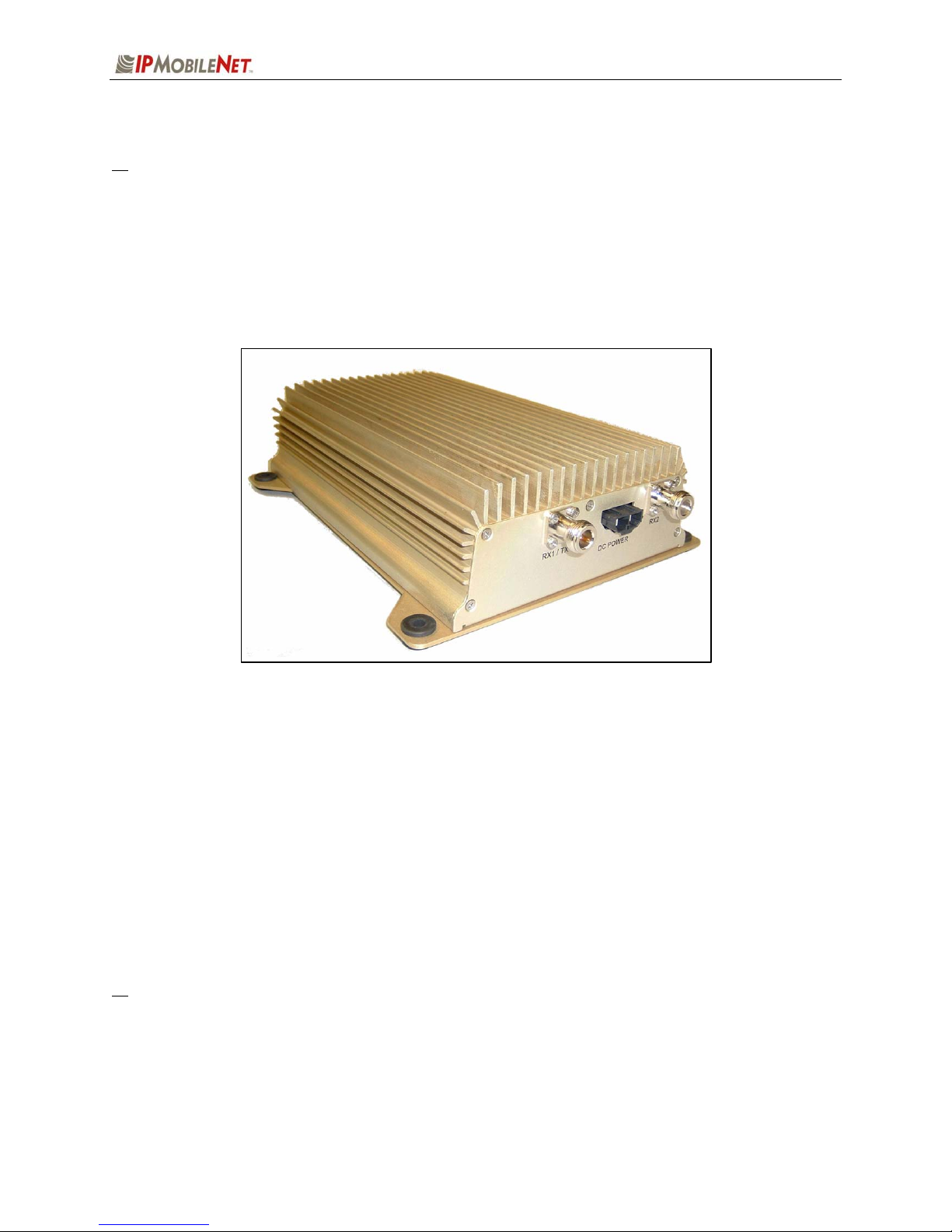
The IPSeries High Speed Mobile Radios are intelligent devices designed for the challenging requirements
of mobile data applications. Mounted in vehicles, other intelligent devices may connect to the serial or
Ethernet ports for connectivity back to the Internet Protocol Network Controller (IPNC) and other such
servers. It provides the mobile link to land-based wired networks.
Figure 1: IPSeries High Speed Mobile Radio (Front View)
Product Functionality
The IPSeries High Speed Mobile Radio utilizes a high-performance, 4-level Frequency-Shift Keying (FSK)
wireless data modem for 32 kbps operation, 16-level FSK for 64 kbps in 25 kHz channels; a multi-layered
approach to signal reliability. It features low power consumption, high performance integrated GPS
receiver. Embedding this technology in the mobile radio lowers the cost of acquiring GPS data from
vehicles and ensures optimal performance.
The mobile radio technology includes Diversity Reception (DR) capability. DR reduces the effects of
fades in a multi-path environment. With the use of two (2) antennae mounted at a calculated distance on
the roof of the vehicle the Diversity Reception System (DRS) minimizes the effects of fading by
intelligently selecting the receiver with a better signal.
Diversity is most effective when the vehicle is in motion.
M64450G25-FCCRpt.doc Page 3

SECTION 1: OVERVIEW
External Features
As seen in the figure below, the mobile radio technology is enclosed in a compact and sturdy aluminum
case. The external features consist of a series of connectors and ports as described in this section.
a The product warranty becomes immediately void if an uncertified or unauthorized individual
removes the mobile radio cover.
Figure 2: IPSeries High Speed Mobile Radio (External Features)
The mobile radio external features consist of the following connectors and ports:
TABLE 1: EXTERNAL FEATURES
FEATURE DESCRIPTION
TX/RX1 Transmitter / Receiver 1 antenna connection
RX2 Receiver 2 antenna connection
Power Connector 13.8 VDC mobile radio power connector
Lock LED Unit ‘Ready’ Status Indicator LED (light emitting diode)
GPS GPS antenna (SMA) connector
Serial Port RS232 Serial Line Internet Protocol (SLIP) interface port
Ethernet Port 10 Base T Ethernet interface port
M64450G25-FCCRpt.doc Page 4

SECTION 2: SETUP AND CONFIGURATION METHOD
Mobile Radio-to-Mobile Computer Setup and Configuration
The following section describes the setup and configuration method for the mobile radio in a vehicle.
Mobile Radio-to-Mobile Computer Setup
Figure 3: High Speed Mobile Radio-to-Mobile Computer Setup
Additional components are required to setup a mobile radio-to-mobile computer configuration, and are
listed in the following table:
TABLE 2: HIGH SPEED MOBILE RADIO-TO-MOBLE COMPUTER COMPONENTS
REQUIRED FOR INSTALLATION
QTY DESCRIPTION
1 IPSeries High Speed Mobile Radio
1 Mobile Computer
1 20-foot serial cable (DB9F – DB9M)
1 IPMobileNet SLIP Port Driver Installation file (SLIP2IPMN.exe)
If using the mobile radio’s Ethernet feature an Ethernet crossover cable is required to replace the
20-foot serial cable.
To configure the mobile radio and computer for this type of setup, follow the instructions on pages
2 through 17 in the Mobile Computer Setup for Communication with the Mobile Radio
Installation Guide (IPMN p/n: 516.80310.IG) available on the Product Documentation CD.
M64450G25-FCCRpt.doc Page 5

SECTION 3: INSTALLATION INSTRUCTIONS
Installation Overview
This chapter provides the basic steps involved in the installation process of an IPSeries High Speed
Mobile Radio into a vehicle. This chapter includes wire routing and connections between the mobile
radio, other components, and the vehicle’s power.
a
To prevent personal injury and vehicle damage, exercise extreme caution throughout the
installation process and follow the reminders listed below.
Follow safety precautions for handling wiring, tools, and a vehicle’s engine.
Handle the vehicle’s battery with extreme caution to avoid burns.
Do not
alter the components listed in the ‘Installation Requirements’ section below, unless
substitutions are noted within this section.
Once the antennae are installed
, as directed within this user manual, all persons must
maintain a distance of no less than 39 inches from the antennae while the mobile radio is in
the transmit mode.
Installation Requirements
The table below lists the documents required to successfully install the mobile radio and connect to the
various components within the vehicle:
TABLE 3: DOCUMENTS REQUIRED FOR HIGH SPEED MOBILE RADIO INSTALLATION
DESCRIPTION PART NUMBER
M64450G25 High Speed Mobile Radio Product Owner’s Manual 516.80528.POM
Installation Guide for Mobile Computer Setup for Communication with
the Mobile Radio (available on the Product Documentation CD, IPMN
516.80310.IG
p/n: 480.0001.001).
M64450G25-FCCRpt.doc Page 6
SECTION 3: INSTALLATION INSTRUCTIONS
The table below lists components that are available for purchase through IPMobileNet, Inc.
TABLE 4: MOBILE INSTALLATION ACCESSORIES
QTY DESCRIPTION IPMN PART NUMBER
4 Screws, Self Tapping #10 X 5/8 37040010-10
1 EMI Filter 127.0020.002
1 Timer, 2 hours 150.0127.004
1 Relay 128.0117.001
1 Relay Socket 128.0116.001
2 Butt Connectors #8 AWG 120.0256.001
1 Terminal, Ring #8 AWG, #10 Screw Insulated 120.0127.001
4 Terminal, Ring #18-22 AWG, #10 Screws Insulated 120.0250.004
4 Terminal, Ring #10-12 AWG, #10 Screws Insulated 120.0250.005
4 Terminal, Disconnect #14-16 F 120.0244.002
18 Terminal, Disconnect #10-12 F 120.0244.003
2 Disconnect Tab, Quad Male 200.1377.001
1 Wire, 12 AWG Black, order 5 ft. 156.0242.001
1 Wire, 12 AWG Red, order 44 ft. 156.0242.003
1 Fuse, 15 AMPS ATO 122.0042.003
2 Fuse, 30 AMPS ATO 122.0042.001
3 Fuse Holder, 12 AWG 120.0253.001
1 Switch, Toggle DPST 144.0136.001
1 Diagram, Mobile Installation (included in this manual) 502.80259.52
1 Diagram, Diversity Antenna Mobile Installation Detail (Typical Install) DT450-10-0201
The table below lists the auxiliary equipment required to complete the installation process.
TABLE 5: AUXILIARY EQUIPMENT
QTY DESCRIPTION IPMN PART NUMBER
1 Serial Cable (DB9MF), 20 ft. 156.0245.020
1 Wire, 8 (133/29) AWG VW-1 Red, by foot, order 19.5 ft. 156.0243.003
1 Wire, 8 (133/29) AWG VW-1 Black, by foot, order 19.5 ft. 156.0243.001
2 Mounting Kit, Permanent Hole (MB8UN) 124.0601.001
Antenna, Radome Type, 410-430 MHz, 3dB Gain (requires 1MB8XN
2
for each antenna)
Antenna, Radome Type, 430-450 MHz, 3dB Gain (requires 1MB8XN
2
for each antenna)
Antenna, Radome Type, 458-470 MHz, 3dB Gain (requires 1MB8XN
2
for each antenna)
Antenna, Radome Type, 470-490 MHz, 3dB Gain (requires 1MB8XN
2
for each antenna)
Antenna, 5/8 Wave, 490-512 MHz, 3dB Gain (requires 1MB8XN for
2
each antenna)
102.0206.001
102.0206.002
102.0206.003
102.0206.004
102.0199.006
M64450G25-FCCRpt.doc Page 7
SECTION 3: INSTALLATION INSTRUCTIONS
Installation Instructions
Pre-Installation Guidelines
Prior to installing new equipment, perform the following steps:
a
1. Remove existing equipment and all related components to include stock clips on radio
wiring harness and antenna.
2. As shown in the figure below, mounting of the mobile radio, delay timer, relay, and EMI
filter (noise filter) will take place in the trunk compartment, unless installing in a vehicle
without a trunk.
Figure 4: Trunk Compartment Installation
Removal of seats, rubber mats, and other obstructions from inside the driver compartment may
be necessary to facilitate routing of wires to the engine and trunk compartments.
3. To ensure appropriate cable and wire routing, exercise the following precautions:
Route cables away from sharp edges that can penetrate cable insulation and damage
wires.
Protect wires with silicone rubber grommets when routing through the engine
compartment firewall or through other holes with sharp edges.
Use high-quality electrical tape when covering exposed wires in the engine
compartment.
Avoid routing cables through areas exposed to extreme heat, such as the exhaust.
Keep wires routed through the engine compartment away from hot and/or moving
parts.
M64450G25-FCCRpt.doc Page 8
4. Prior to drilling holes in the engine compartment firewall, inspect both sides to avoid
obstructions.
5. For grounding point, use the engine block or the negative (-) terminal of the vehicle battery.
Ground connection surfaces must be free of paint, rust, and other corrosion to maximize
performance and avoid damage. Do not tie to the vehicle chassis.
6. To simplify troubleshooting problems, label all connecting points and wires.
Mounting the High Speed Mobile Radio
To mount the mobile radio, perform the following steps:
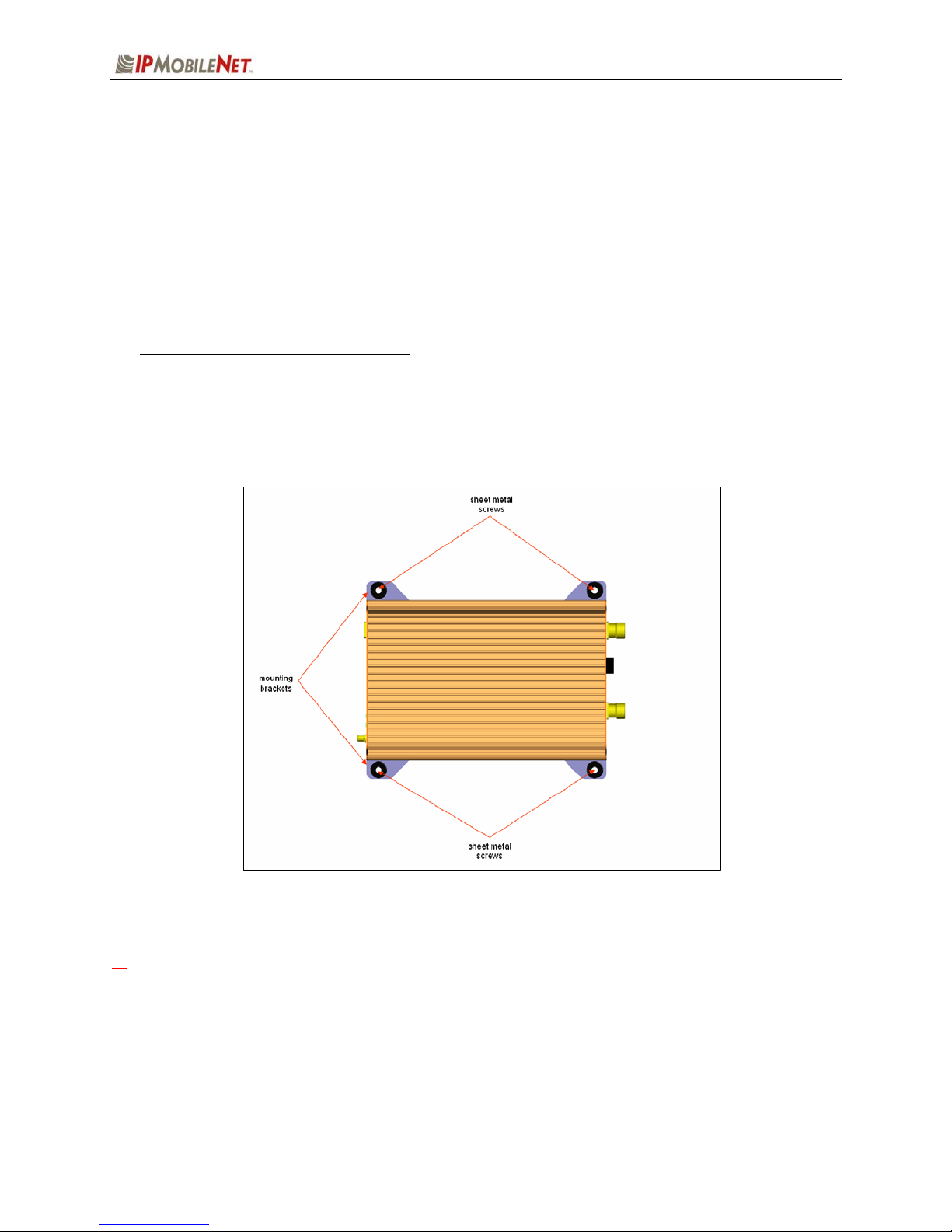
Step 1 As shown in the figure below, secure the mobile radio into the trunk compartment.
Insert four (4) sheet metal screws in the mobile radio brackets.
SECTION 3: INSTALLATION INSTRUCTIONS
Figure 5: High Speed Mobile Radio Mounting
a
If less than four (4) screws are used, the mobile radio can become loose in the trunk
compartment. This may cause the mobile radio not to function properly.
When inserting screws, be careful not to disturb the vehicle’s gas tank.
M64450G25-FCCRpt.doc Page 9

SECTION 3: INSTALLATION INSTRUCTIONS
Serial Cable Connection and Routing
The serial cable connects the mobile radio to the mobile computer located in the driver compartment.
To connect the serial cable, perform the following steps:
Step 1 Attach the 20-foot serial cable male connector (DB9M) to the mobile
radio.
Step 2 Route the female connector (DB9F) to the driver compartment and
connect to the serial port located on the rear of the mobile computer.
Route the serial cable to minimize foot pressure and other potential
stresses. Use split loom tubing and nylon cable ties for cable protection.
Ethernet Setup
The user also has the option to connect the mobile radio and the mobile computer via Ethernet.
To connect the Ethernet cable, perform the following steps:
Step 1 Attach the Ethernet cable (minimum 20 feet) to the Ethernet port on the rear of the
mobile radio.
Step 2 Route the other end of the Ethernet cable to the driver compartment and connect to
the Ethernet port located on the rear of the mobile computer.
Route the cable to minimize foot pressure and other potential stresses. Use split loom
tubing and nylon cable ties for cable protection.
Delay Timer Installation
To install the Delay Timer, perform the following steps:
Step 1 Secure Delay Timer to the trunk compartment of the vehicle inserting screws in the
appropriate locations using care not to puncture the vehicle’s gas tank.
Step 2 Route the black wire (#12 AWG) from ground connection on the Delay Timer to the
vehicle chassis (see Figure 8).
Step 3 Route and wire the red wire (#8 AWG) from the positive (+) terminal connection on
the vehicle battery connection via the in-line fuse toward the battery connection on
the Delay Timer.
Connect the red wire (#8 AWG) to the two red wires (#12 AWG). Route and wire
the red (#12 AWG) wires to the two (2) battery connections on the Delay Timer.
Figure 6
Figure 7
M64450G25-FCCRpt.doc Page 10

SECTION 3: INSTALLATION INSTRUCTIONS
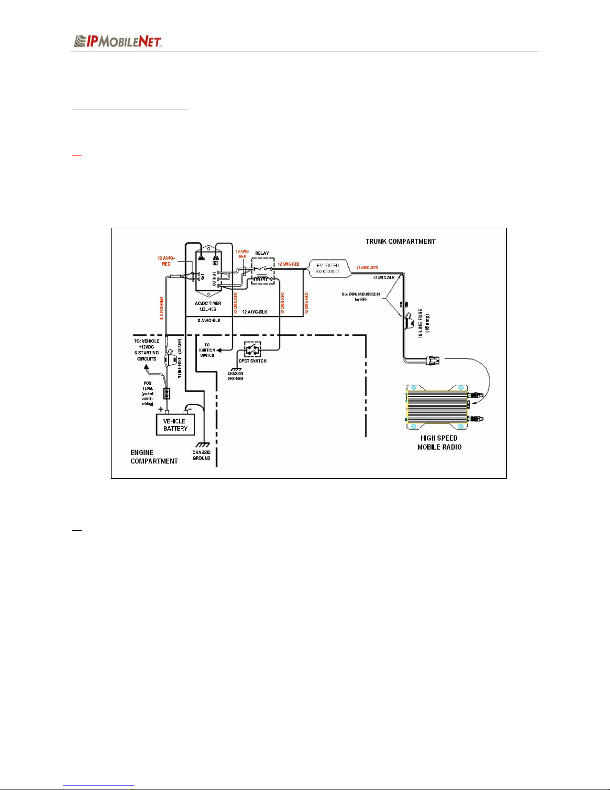
Figure 8: Delay Timer Installation
Step 4 Route a red wire (#12 AWG) from the ignition connection on the Delay Timer to the
ignition switch in the driver compartment (see the figure above). The ignition wire
should be fused with 2A fuse.
Step 5 Route a red wire (#12 AWG) from the first and last output connections on the Delay
Timer to the Automotive Power Relay.
Step 6 Route and wire a red (#12 AWG) wire from the second output connection on the
Delay Timer to the last output connection on the Delay Timer.
Step 7 Route and wire a red (#12 AWG) wire from the last output connection on the Delay
Timer to the Automotive Power Relay coil at the position shown in the figure above.
Step 8 Route and wire a black (#8 AWG) wire from the junction (negative battery post
group) in the trunk compartment to the negative (-) terminal on the vehicle battery.
Step 9 Wire the red (#12 AWG) wire to the battery input on the Delay Timer and route the
black (#8 AWG) portion of the wire to the positive terminal on the battery via an inline fuse (30 AMP).
M64450G25-FCCRpt.doc Page 11
SECTION 3: INSTALLATION INSTRUCTIONS
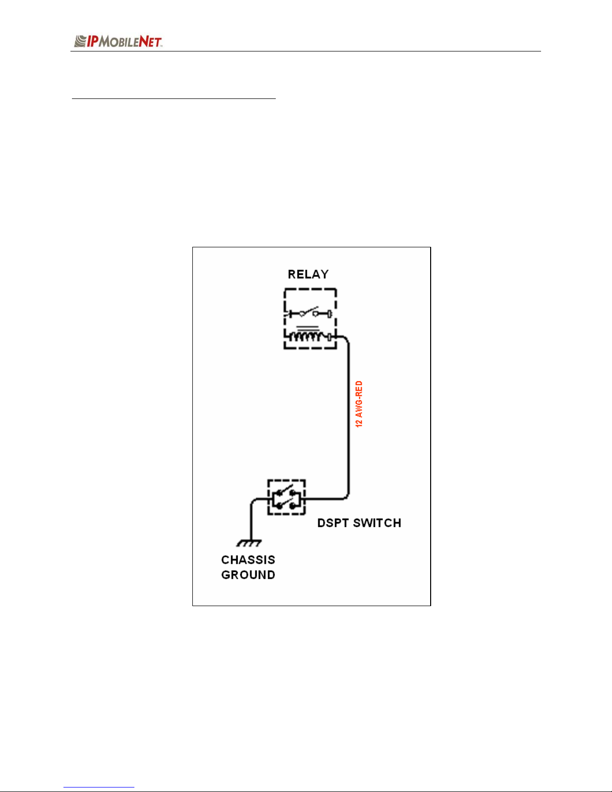
Switch Installation (DPST Heavy Duty Toggle)
To install the switch, perform the following steps:
Step 1 Mount the switch in the selected location.
Step 2 Route and wire a red wire (#12 AWG) from the switch to the Automotive Power Relay
(see the figure below).
Step 3 Ground the switch by routing and wiring a black wire from the switch to the chassis
ground.
Figure 9: Carling Switch Installation
M64450G25-FCCRpt.doc Page 12
SECTION 3: INSTALLATION INSTRUCTIONS
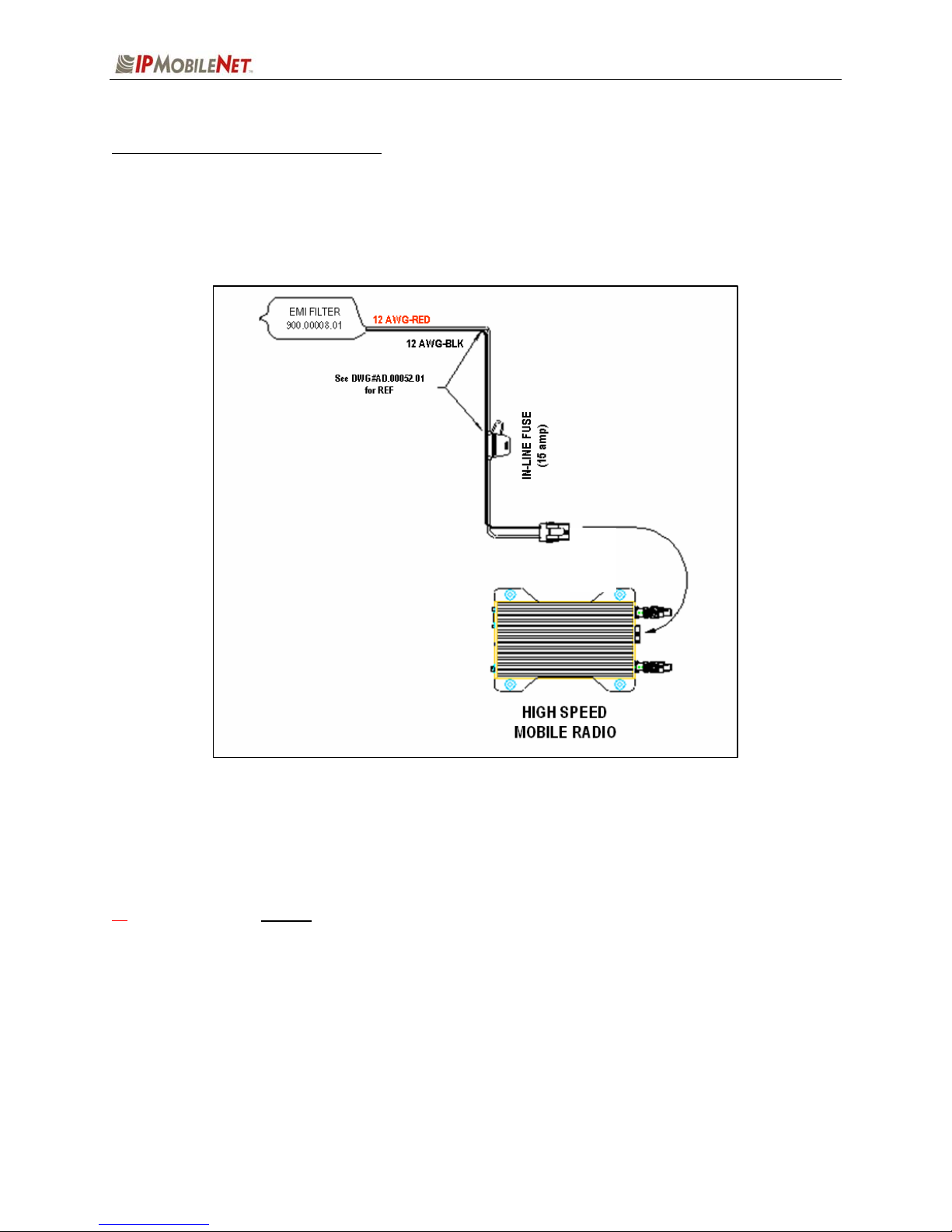
Mobile Radio Power Supply Installation
To install the mobile radio power connection, perform the following steps:
Step 1 Route and connect the power cable to the EMI filter, as shown in the figure below.
Figure 10: Power Supply Installation
Step 2 Route and connect the other end of the power cable to the rear of the mobile radio
to the power connector (13.8 VDC) connection.
a
WARNING! Do not connect power before installing and connecting proper antenna or dummy
load on the TX/RX1 port. The mobile radio must never be allowed to transmit without a suitable
output load.
Step 3 Install the GPS antenna. The GPS antenna is required for the mobile radios and
the base stations.
M64450G25-FCCRpt.doc Page 13
 Loading...