

IP-Link iLAN-100 Installation Manual
www.wattmaster.com
Installation Guide
IP-Link
SERIAL
MODE
POW
SNET
ER
PW
R
OE415
IP-Link
www.wattmaster.com
10/100BASE-T
LINK ACT

Table Of Contents
General Information ......................................................................................................................................... 3
CommLink II and IP-Link Connection ...........................................................................................................................................3
System Overview .........................................................................................................................................................................3
System Requirements ..................................................................................................................................................................3
Programming.................................................................................................................................................... 4
Programming the IP-Link..............................................................................................................................................................4
Connecting the IP-Link/CommLink II Network..............................................................................................................................6
Proxy and Firewall Compatibility ..................................................................................................................................................8
Troubleshooting ............................................................................................................................................... 9
Troubleshooting Procedures ........................................................................................................................................................9
Appendix A ................................................................................................................................................................................10
Appendix ........................................................................................................................................................ 10
Notes .............................................................................................................................................................. 11
WattMaster Controls, Inc.
8500 NW River Park Drive · Parkville, MO 64152
Toll Free Phone: 866-918-1100
PH: (816) 505-1100 · FAX: (816) 505-1101 · E-mail: mail@wattmaster.com
Visit our web site at www.wattmaster.com
Form: WM-IPLNK-TGD-01B Copyright 2007 WattMaster Controls, Inc.
Connect One® and iLAN® are registered trademarks of Connect One, Ltd.
WattMaster Controls, Inc. assumes no responsibility for errors or omissions.
This document is subject to change without notice.

General Information
IP-Link Installation Guide
CommLink II and IP-Link Connection
The IP-Link (iLAN-100) provides a TCP/IP Port connection from
the WattMaster control system to a building’s Ethernet LAN,
providing communications with the control system through any
computer (with Prism Software installed) connected to the LAN
or the Internet (if confi gured for access through your LAN’s
Internet Firewall).
Using standard TCP/IP Protocol, with WattMaster’s Prism
Software you are able to monitor and confi gure your controllers
without a modem or a direct connection from a PC. Utilizing
existing routers, proxies, or fi rewalls allows a PC running Prism
to connect to a controller in a remote accessible location or building. Several dialer/connection profi les can be created to facilitate
monitoring several sites.
System Overview
The IP-Link is a stand-alone network appliance that has been
adapted to connect the CommLink II (with IP-Link EPROM
chip) to a 10BaseT or 10/100 network connection. The IP-Link
will require an IP address on the local network or a routable
IP address provided by an ADSL or Cable modem if it is to be
accessed through the Internet. The PC will require a dialup or
Ethernet network connection to the Internet or local network with
routes to the IP-Link. Check with your local IT Department in
regards to your network routing needs.
System Requirements
T o program the IP-Link to work with Prism, you will need:
• The Prism Software CD (supplied with the IP-Link)
• A PC with an RS-232 serial communications port
(supplied by others)
• Ethernet RJ-45 6 ft. long cable (supplied with the IP Link) or a longer RJ-45 Ethernet cable (supplied by
others) and an available port to connect the IP-Link to
the LAN
• Microsoft Windows 98, NT, 2000, or XP (must be
installed on the PC you are going to use)
• The IP-Link Connect One’s iChip Confi guration
Software (Windows-based program on the supplied CD)
• IP-Link Serial Cable with two DB-9 connectors (and
one DB-25 connector for computers that require
a DB-25 instead of a DB-9 connector)—supplied with
the IP-Link
• An IP Address, Subnet Mask, and Gateway Address
for the IP-Link confi gured for your LAN by your
network administrator
The TCP/IP connection itself is a TCP connection made on a
single port number and is static in nature. Firewall and proxy
servers can easily be confi gured to allow traffi c to and from this
device. The nature of the data is raw in form and comprised of
packets native to Prism software. The IP-Link will respond to
ICMP traffi c (PING) for verifi cation of proper confi guration, but
Prism software is required in order to send and receive data to
the IP-Link and CommLink II.
• MiniLink or MiniLink Polling Device, connected to the
CommLink and Controller(s) and powered on
• CommLink II set to Multi-mode, connected to the
MiniLink or MiniLink Polling Device and powered on
• EPROM chip SS0058—Remove the old CommLink
Chip (SS0039) from the CommLink and replace it with
the IP-Link EPROM chip SS0058 (supplied)
NOTE: To quickly confi gure the IP-Link, you may enter all of
the required information in the
of the iChip Confi guration Software. Please note:
The IP-Link is also referred to as the iLAN 100 in the
software screens.
Quick Setup Screen
Operator Interface 3
IP-Link Installation Guide
Programming
Programming the IP-Link
Connecting the IP-Link to your PC
1. Connect the IP-Link’s supplied 120/9 VAC power
supply to a 120/1/60 duplex outlet. Do not plug the
power supply into the IP-Link yet (you will do this in
Step 4).
2. Connect one DB-9 connector (or DB-25 connector if your computer requires one) to the serial port
connector on the IP-Link and connect the other DB-9
connector to COM1 or COM2 serial port on your PC.
3. Connect one end of the Ethernet RJ-45 cable to the
IP-Link’s 10BaseT connector and connect the other
end to a 10BaseT port on your LAN.
4. Power on the IP-Link by connecting it to the power
supply cable.
5. Insert the CD in the CD drive of your PC. Run the
Setup.exe in the \Software directory to install the
confi guration software.
Installing and Starting the iChip Confi g
Program
The iChip Confi g Program enables you to set the IP-Link’s IP
address and network mask. The gateway address is optional but
not necessary for proper operation. T o install the program from the
CD, simply install the setup.exe program found in the \Software
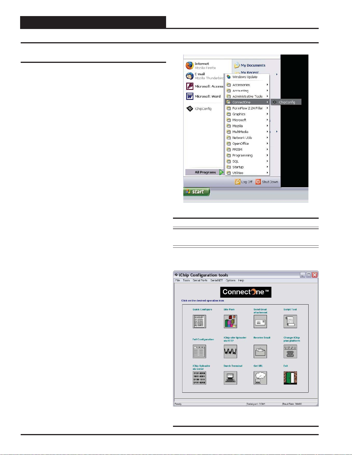
directory. After the program is installed, open it by clicking Start
->All Programs->ConnectOne->iChipConfi g (see Figure 1).
Figure 1: Connect One Directory
NOTE: iChip Confi g will try to connect to the IP-Link using fi rst
COM1 and then COM2, in that order.
Open the iChip Confi g Program.
device is found, the Main Menu will appear. (See Figure 2).
When the Connect One
4
Figure 2: The iChip Confi g Program Main Menu.
Operator Interface
 Loading...