

IP Gear SmartCell 111L, Cellulink Smartcell 111L User Manual
Cellulink Smartcell 111L
Cellular Gateway
for a Single Analog Line
User’s Guide
http://www.ipgear.co.il

IP Gear SmartCell 111L User Guide
Version
We thank you for purchasing the “SmartCell 111L”. “SmartCell 111L” is a
member of IP Gear’s family of state of the art gateways.
This manual is applicable to IP Gear 111L with software versions 0218 or
higher. These apply to units with part number Q11-111093 (900/1800MHz) and
Q11-111083 (850/1900MHz) with version numbers: B or higher. The part
number and version number are marked on a sticker located at the bottom or the
side of the unit (see section 1.3 – product identification). Other versions may
differ slightly in some aspects.
Disclaimer of liability
IP Gear Ltd. and its distributors assume no responsibility for any damage or loss
resulting from the use of its products or this user manual. IP Gear Ltd. and its
distributors assume no responsibility for any loss or claims by third parties,
which may arise through the use of its products.
Registration and Type Approval
Smartcell 111L carries CE Certification.
Corporate contacts
IP Gear Ltd.
I.D.: 513765297
Postal Address: 2 Prof. Pekris St., Rehovot 76702, Israel.
E-mail:
sales@ipgear.co.il
Web address:
http://www.ipgear.co.il
© IP Gear Ltd. All rights reserved.
IP Gear, the IP Gear Logo, CelluLink and CellBox are registered trademarks of
IP Gear Ltd. Other product and brand names may be trademarks or registered
trademarks of their respective owners.
January 2006
Page 1

IP Gear SmartCell 111L User Guide
Table of Contents
1 Introduction..................................................3
1.1 Overview.....................................................................................................3
1.2 Packing List ................................................................................................3
1.3 Product Identification..................................................................................4
2 Product Description.....................................5
2.1 Main Components.......................................................................................5
2.2 LED Indications..........................................................................................6
3 Installation....................................................7
3.1 Physical Installation....................................................................................7
3.2 Configuration of the PABX ........................................................................9
3.3 Getting Started..........................................................................................10
3.4 Post-Installation Tests...............................................................................10
3.5 User Guidance...........................................................................................11
4 Features and Programming Instructions..12
4.1 General......................................................................................................12
4.2 Audio Gain................................................................................................12
4.3 Immediate Dialing ....................................................................................13
4.4 Interdigit Timeout.....................................................................................14
4.5 Calling Number Identification Restriction (CLIR)...................................15
4.6 PIN Code Programming............................................................................15
4.7 Toll Restriction .........................................................................................17
4.8 Call Duration Limit...................................................................................18
4.9 Set Reverse Polarity Signaling Method ....................................................18
4.10 Set Pulse Drop Signaling Method.............................................................19
4.11 Set Pulse Drop Width................................................................................19
4.12 Erase SMS Inbox of the SIM card............................................................20
4.13 Network-Lock...........................................................................................20
4.14 Restore Factory Default............................................................................21
4.15 DTMF Programming Summary................................................................22
4.16 Factory Default Values .............................................................................23
4.17 Call Progress tones....................................................................................23
5 SMS Commands...........................................24
5.1 General......................................................................................................24
5.2 GET command table .................................................................................24
5.3 SET command table..................................................................................25
6 Troubleshooting...........................................26
7 Specifications................................................27
Page 2

IP Gear SmartCell 111L User Guide
1 Introduction
1.1 Overview
The Smartcell 111L gateway enables direct connection of an organization's
internal telephony system to any commercial cellular network, via an already
existing Private Automatic Branch Exchange (PABX) system.
The Smartcell 111L interfaces with a regular two-wire analogue line interface
and a GSM cellular network to create a cellular gateway. Smartcell 111L
operates via dual band GSM cellular networks (900/1800MHz). A special
version operates at 900/1900MHz.
The functionality of the Smartcell 111L is usually transparent to users when used
with a PABX with LCR (Least Cost Routing) capability. The PABX recognizes
Smartcell 111L as a trunk interface and the routing is done in the PABX itself. In
a PABX with no LCR capability, the user selects the proper trunk for the call. In
this case, the user has to know when to use the trunk with the 111L and when to
use other trunks.
The Smartcell 111L can be used with a plain analog telephone as well. In this
case, every time you go off-hook the 111L will send you a dial tone. You can use
this configuration as a replacement for a fixed line telephone.
The Smartcell 111L can be used to send and receive SMS, fax and data
transmissions (These features are optional; contact your technical support for
further information).
1.2 Packing List
The Smartcell 111L is shipped with the following components:
Smartcell 111L unit
An antenna with a 3-meter long cable.
Power supply (AC adaptor with rated output 9VDC, 1A)
A set of 3 screws
This user manual
Optional items
The following items may be supplied on a separate order
Data cable for fax and SMS
An antenna with a 15-meter long cable.
Page 3
IP Gear SmartCell 111L User Guide
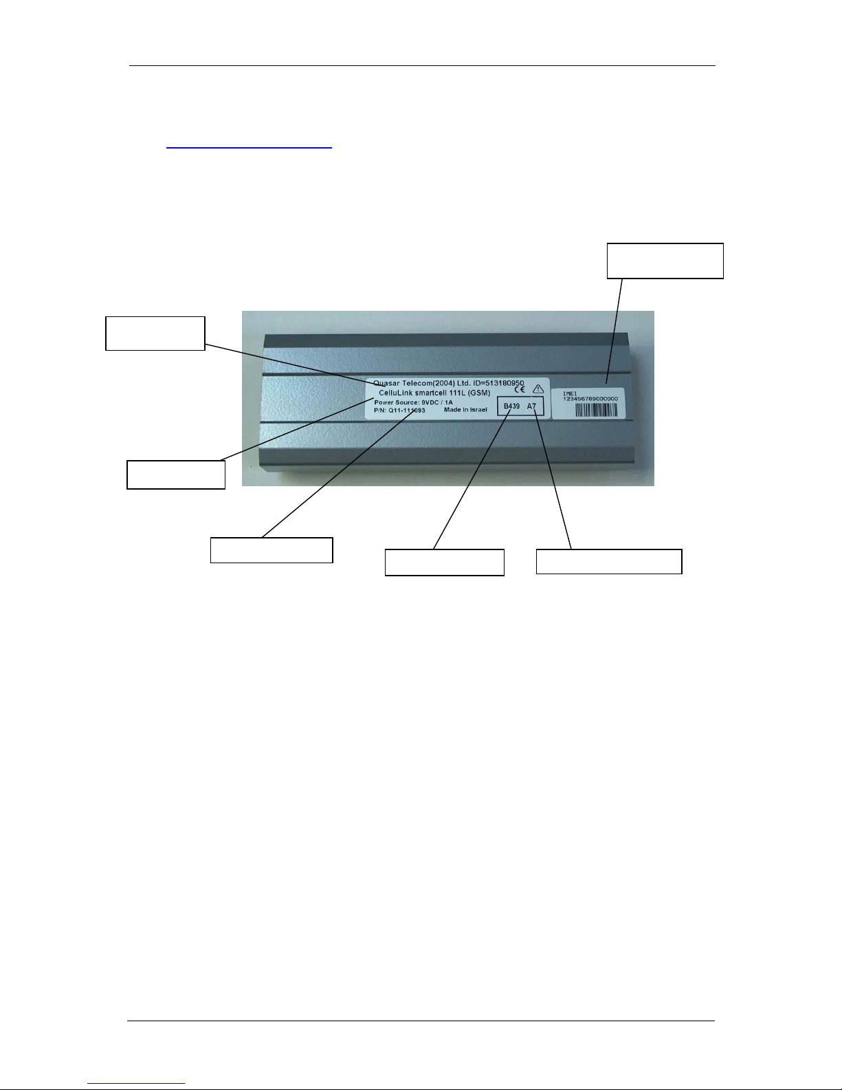
1.3 Product Identification
The product can be easily identified by the info on the sticker found on the
bottom side:
.
IMEI Number
Version Number
Batch Number
Part Number
Power Source
Product Type
Page 4
IP Gear SmartCell 111L User Guide
2 Product Description
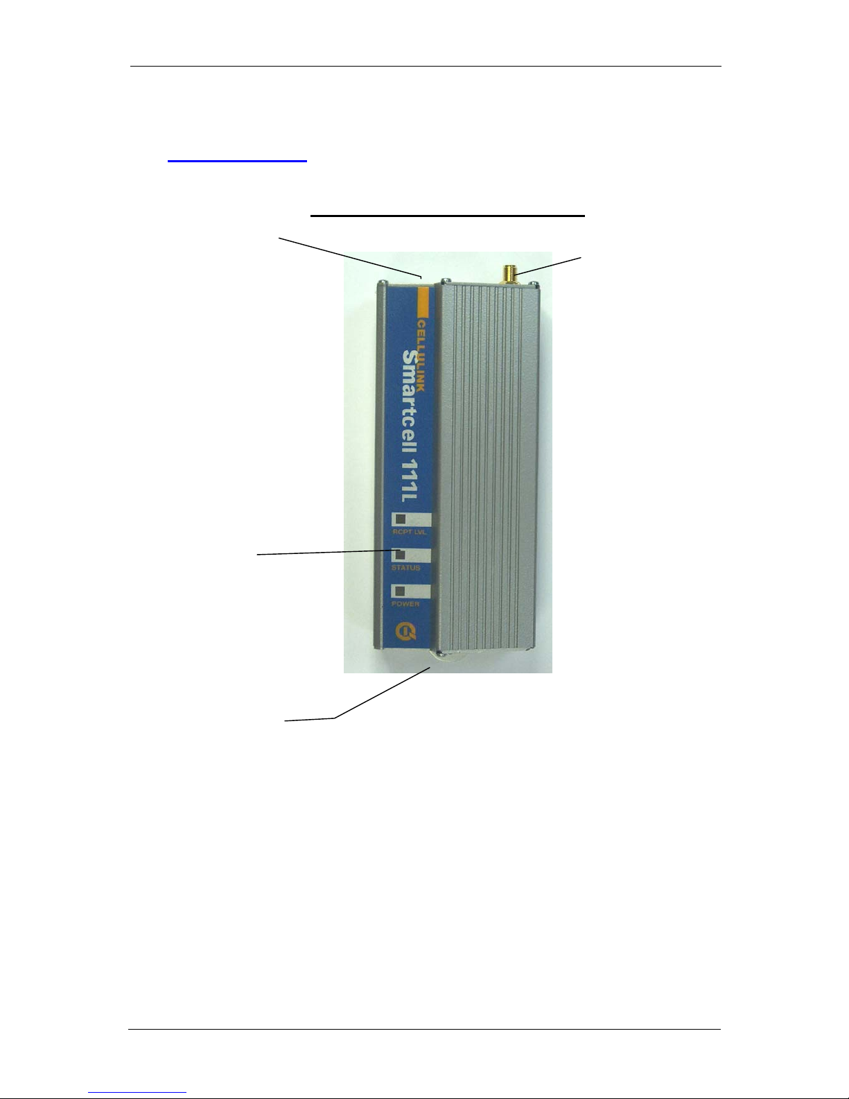
2.1 Main Components
Figure 2-1 outlines the main components of the Smartcell 111L.
Figure 2-1: RJ-11 Connector pin layout
SIM
Drawer
Antenna
Connector
LED Panel
Connection Panel
Page 5
IP Gear SmartCell 111L User Guide
2.2 LED Indications
The LEDS on the front panel of the unit provide indications to the operation
status of the unit, as described in Table 2-1.
Table 2-1: LED Indications
LED Description Operation
RCPT.LVL
(RECEPTION
LEVEL)
Indicates
the
reception
level of the
Smartcell
111L.
Green - High reception.
Orange - Medium reception
Red - Low reception
Off - Very low reception or no reception at all
Note: to indicate proper activity of the unit in idle
(no call), the LED will turn off for a few seconds
every 15 seconds of operation. During a call the
indication is frozen to the one that existed when
the call had started.
STATUS Indicates
the
Smartcell
111L
operational
status.
On – 111L is handling a call.
Blinking (0.2S on, 0.2S off) – During ringing
Off – 111L is idle and no calls are being handled.
Indications
• Slow blinking (0.5S on, 0.5S off) – 111L is
initializing following power up.
• Fast blinking (0.1S on, 0.1S off) – SIM card
not inserted or an error has occurred in the
PIN code entry. The PIN code must be either
disabled or enabled with 1234 entry.
• Mostly on (0.5S on, 0.1S off) – Toll
restriction is activated.
Special Indications:
• Blinking (0.3S on, 0.3S off) – During
DTMF programming session.
• Blinking (0.2S on, 1S off) – During local
PC session.
POWER Indicates
the status of
the power
connection.
On – 111L is powered on.
Off – 111L is powered off.
Page 6

IP Gear SmartCell 111L User Guide
3 Installation
3.1 Physical Installation
Select a location for the Smartcell 111L that is indoors and in the proximity of a
power socket and near a proper location for the antenna.
3.1.1 Main unit
Drill holes in the wall to match the wall mounting brackets of the Smartcell 111L
and screw the unit onto the wall. The unit must be placed in the orientation
shown in Figure 2-1, with the antenna socket pointing upward and the
connection panel pointing downward.
3.1.2 Antenna
Connect the antenna provided with the Smartcell 111L to the antenna connector
located on top of the unit. Place the antenna at least one meter away from
Smartcell 111L, in an upright position. The antenna should be placed on a metal
plate. If you install more than one unit, each antenna should be on a separate
plate – minimum distance of 30cm between the antennas. The antenna base is
magnetic, so an iron plate will be the best choice.
3.1.3 SIM card
The next step is to insert the SIM card into the unit. Before you do it, make sure
you have the right SIM. It is easier to use a SIM with no PIN code. If you want
to use the PIN code, start with a SIM that has 1234 as a PIN code. (You can
program it with any mobile phone). You can then use the default PIN or change
it to any other PIN you like, using the DTMF programming process. It is very
important to save the PIN code in a secure place.
The SIM card should normally be with no call waiting and no voice mail. If
needed – use a mobile phone to define the message-centre for SMS transmission.
To insert the SIM card into the SIM drawer located on top of the unit - open the
SIM drawer by inserting a dull, thin object into the appropriate slot. Place the
SIM card in the tray making sure that the SIM card contacts are away from you.
Close the SIM card tray.
3.1.4 Connection to PABX
Connect a routed trunk port from the PABX to the LINE port (shown in Fig 3-2).
The routed trunk port is a trunk interface that was pre-programmed in the PABX
to deliver cellular calls.
Page 7
IP Gear SmartCell 111L User Guide
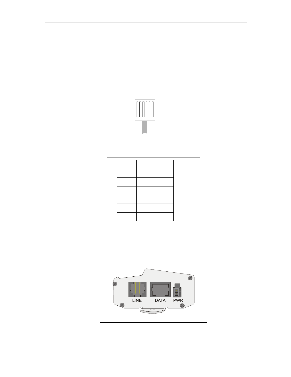
3.1.5 RJ-11 Connector Pin Layout
Figure 3-1 illustrates the pin layout of the RJ-11 line connector. Table 3-1 details
the pin-to-wire layout of the RJ-11 connector. One end of the cable is connected
to the (FXS) Line interface of the Smartcell 111L and the other end is connected
to the (FXO) trunk interface of the PABX.
Figure 3-1: RJ-11 Connector pin layout
1 2 3 4 5 6
Table 3-1: RJ-11 Connector Pin Layout
PIN # FUNCTION
1 Reserved
2 Tip
3 Tip
4 Ring
5 Ring
6 Reserved
Warning: Do not use the reserved pins.
Note: The line can use either pins 3 and 4 or pins 2 and 5.
3.1.6 Connection Panel
Figure 3-2: SmartCell 111L Connector Panel
Page 8
 Loading...