

IPGARD SDVN-2S, SDVN-2D-P, SDVN-2D, SDVN-2S-P, SDVN-4S-P Quick Start Manual
...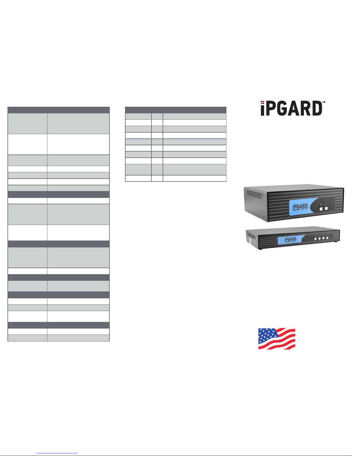
TECHNICAL SPECIFICATIONS WHAT’S IN THE BOX
VIDEO
Host Interface
2-Port SH: (2) DVI-I 29-pin F;
2-Port DH: (4) DVI-I 29-pin F;
4-Port SH: (4) DVI-I 29-pin F;
4-Port DH: (8) DVI-I 29-pin F
User Console
Interface
2-Port SH: (1) DVI-I 29-pin F;
2-Port DH: (2) DVI-I 29-pin F;
4-Port SH: (1) DVI-I 29-pin F;
4-Port DH: (2) DVI-I 29-pin F
Max Resolution
2560 x 1600 @ 60Hz;
3840 x 2160 @ 30Hz
DDC 5 volts p-p (TTL)
Input Equalization Automatic
Input Cable Length Up to 20 ft.
Output Cable Length Up to 20 ft.
USB
Signal Type USB 1.1 keyboard and mouse only
USB Connectors
2-Port: (2) USB Type B;
2-Port w/CAC: (4) USB Type B;
4-Port: (4) USB Type B;
4-Port w/CAC: (8) USB Type B
User Console
Interface
(2) USB Type A for keyboard/mouse
connections;
W/CAC: (1) USB Type A for CAC
AUDIO
Input
2-Port: (2) Connector stereo 3.5 mm
female;
4-Port: (4) Connector stereo 3.5 mm
female
Output (1) Connector stereo 3.5 mm female
POWER
Power Requirements
12-VDC, 2-A power adapter with
center-pin positive polarity
ENVIRONMENT
Operating Temp 32° to 104° F (0° to 40° C)
Storage Temp -4° to 140° F (-20° to 60° C)
Humidity
0-80% relative humidity,
noncondensing
OTHER
Emulation Keyboard, mouse, and video
User Controls Front-panel buttons
PART NO. QTY DESCRIPTION
SDVN-2S 1 2-Port, Single-Head, DVI-I
SDVN-2S-P 1 2-Port, Single-Head, DVI-I with CAC
SDVN-2D 1 2-Port, Dual-Head, DVI-I
SDVN-2D-P 1 2-Port, Dual-Head, DVI-I with CAC
SDVN-4S 1 4-Port, Single-Head, DVI-I
SDVN-4S-P 1 4-Port, Single-Head, DVI-I with CAC
SDVN-4D 1 4-Port, Dual-Head, DVI-I
SDVN-4D-P 1 4-Port, Dual-Head, DVI-I with CAC
PS12VDC2A 1
12-VDC, 2-A power adapter with
center-pin positive polarity.
1 Quick Star t Guide
SDVN-2S, SDVN-2S-P,
SDVN-2D, SDVN-2D-P,
SDVN-4S, SDVN-4S-P,
SDVN-4D, SDVN-4D-P
2 Port and 4 Port DVI-I secure KVM switch
Advanced 2-Port and 4-Port
Secure Single-head or Dual-head
DVI-I KVM Switch with Audio
with or without CAC Support
Quick Start Guide
A full manual can be downloaded from
www.ipgard.com/documentation/
DESIGNED
AND MADE
IN THE USA
NOTICE
The information contained in this document
is subject to change without notice. iPGARD
makes no warranty of any kind with regard
to this material, including but not limited to,
implied warranties of merchantability and
tness for a particular purpose. iPGARD
will not be liable for errors contained
herein, or for incidental or consequential
damages in connection with the furnishing,
performance, or use of this material. No
part of this document may be photocopied,
reproduced, or translated into another
language without the prior written consent
from iPGARD, Inc.
20170518
Toll Free: (888)-994-7427
Phone: (702)-990-0523
Fax: (702)-441-5590
WWW.iPGARD.COM
DVI-I IN
AUDIO OUT
DVI-I OUT
USB IN
USB OUT
CAC IN
CAC OUT
AUDIO IN
1 2 3 4
SDVN-4S-P
SDVN-4S
SDVN-4S-P
SDVN-4S-P ONLY
DVI-I IN
AUDIO OUT
DVI-I OUT
USB IN
USB OUT
CAC IN
CAC OUT
AUDIO IN
1 2 3 4
SDVN-4D-P
SDVN-4D
SDVN-4D-P
SDVN-4D-P ONLY
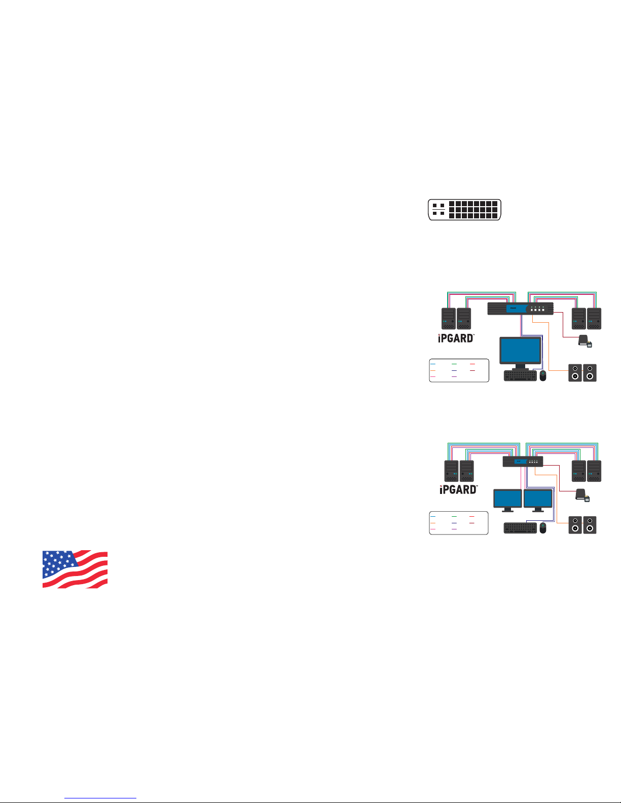
EDID LEARN HARDWARE INSTALLATION FIGURE 1. DVI-I CONNECTOR
FIGURE 2. SINGLE-HEAD APPLICATION
DIAGRAM
FIGURE 3. DUAL-HEAD APPLICATION
DIAGRAM
DVI-I Connector
1. Ensure that power is turned off or
disconnected from the unit and the
computers.
2. Use DVI-I cables to connect the DVI-I
output ports from each computer to the
corresponding DVI-I in ports of the unit.
3. Use a USB cable (Type-A to Type-B) to
connect a USB port on each computer to
the respective USB ports of the unit.
4. Optionally, for CAC models, connect a
CAC (Common Access Card, Smart Card
Reader) to the CAC port in the user
console interface.
5. Optionally, connect a stereo audio cable
(3.5 mm to 3.5 mm) to connect the
audio output of the computer(s) to the
audio in ports of the unit.
6. Connect monitor(s) to the DVI-I out
console port of the unit using
DVI-I cable(s).
7. Connect a USB keyboard and mouse in
the two USB console ports.
8. Optionally, connect stereo speakers to
the audio out port of the unit.
9. Finally, power on the secure KVM switch
by connecting a 12-VDC power supply to
the power connector, and then turn on all
the computers.
Note: You can connect one monitor to the
single-head KVM switch and two
monitors to the dual-head KVM
switch. The computer connected
to port 1 will always be selected by
default after power up.
DESIGNED
AND MADE
IN THE USA
The KVM switch is designed to learn a
connected monitor’s EDID upon power up. In
the event of connecting a new monitor to the
KVM a power recycle is required.
The KVM switch will indicate the unit’s
EDID learn process is active by ashing
the front panel’s LEDs in sequential order.
Starting with the LED above button “1” on
the front panel, each LED will ash green for
approximately 10 seconds upon beginning
the EDID learn. Once all the LEDs stop
ashing, the LEDs will cycle and the EDID
learn will be complete.
If the KVM switch has more than one video
board (such as dual-head and quad-head
models), then the unit will continue to learn
the EDIDs of the connected monitors and
indicate the progress of the process by
ashing the next port selection green and
blue push-button LEDs respectively.
A monitor must be connected to the video
output port located in the console space at
the back of the KVM switch during the EDID
learn process.
If the read EDID from the connected monitor
is identical to the current stored EDID in the
KVM switch, then the EDID learn function
will be skipped.
Note: There are up to 2 computers can be
connected to 2-port model. There are up
to 4 computers can be connected to 4-port
model.
 Loading...