

IPG RSA 2024-SB Operations Manual & Parts List
RSA 2024-SB
RANDOM SEMI-AUTOMATIC CASE SEALER
Serial Numbers TM122 or TM622 XX X XXX

UM122TW / UM622TW UDM10012
2

TABLE OF CONTENTS
Section 1 Table Of Contents------------------------------------------------- 3
Section 2 Technical And Field Assistance------------------------------ 4-5
Section 3 Warranty-------------------------------------------------------------- 6
Section 4 Description Of The RSA 2024-SB Case Sealer----------- 7
Section 5 Important Safeguards-------------------------------------------- 8-15
Section 6 Specifications------------------------------------------------------- 16-21
Section 7 Set Up Procedures------------------------------------------------ 22-35
Section 8 Operating Instructions------------------------------------------- 36-40
Section 8 Troubleshooting--------------------------------------------------- 41-43
Section 9 Recommended Spare Parts List------------------------------ 44
Section 10 Preventive Maintenance----------------------------------------- 45-49
Section 11 Machine Maintenance & Adjustment------------------------ 50-52
Section 12 Optional Equipment----------------------------------------------- 53
Section 13 Schematic Diagrams---------------------------------------------- 54-68
Section 11 Appendix A-Illustrations And Parts Lists------------------ 69
UM122TW / UM622TW UDM10012
3

TECHNICAL ASSISTANCE
Technical Support
This manual covers the Interpack Model RSA 2024-SB Random Side Belt Case Sealer. It has
been set up and tested in our factory with Intertape manufactured pressure sensitive tapes. The
airline and pressure conditions of the testing will differ from customer systems. The machine
may require adjustments to best fit operating needs. If any problems occur when setting up or
operating this equipment, please contact the authorized distributor from where you purchased
this item.
If contact with the authorized distributor is not possible, Interpack Technical Support is
available. Should the need to contact Interpack Technical Support arise, please have the
Case Sealer model number and serial number on hand. This information can be found on the
nameplate of the side panel of the machine. Interpack Technical Support is available during
normal business hours (Eastern Time).
PHONE 800-474-8273 Option 3
If you have a technical question that does not require an immediate response, you may contact
Interpack by fax.
FAX 800-462-1293
Replacement Parts
Order parts by item number, part description and quantity required. Replacement parts
are available from your Authorized Interpack Distributor exclusively.
Should you require assistance selecting the correct part, you may call:
Intertape Polymer Group
Interpack Machinery
Tel: 1-800-474-8273 Option 3
Fax: 1-800-462-1293
MODEL:
SERIAL NUMBER:
DISTRIBUTOR PURCHASED FROM:
DATE OF PURCHASE:
UM122TW / UM622TW UDM10012
4

FIELD SERVICE ASSISTANCE
This machine is designed to provide years of trouble free operation. If any problems
arise with this machine during the normal course of operation, your properly trained and
qualified internal service personnel should be able to repair any issues after consulting
the Trouble Shooting section of this manual.
Service support is available from your Authorized Interpack Distributor at additional cost
if the problem cannot be remedied after consulting the Trouble Shooting section of this
manual.
UM122TW / UM622TW UDM10012
5

WARRANTY
E
QUIPMENT WARRANTY AND LIMITED REMEDY: The following warranty is made in lieu of all other warranties,
express or implied, including, but not limited to, the implied warranty of merchantability, the implied
warranty of fitness for a particular purpose, and any implied warranty arising out of a course of dealing, a
custom or usage of trade:
Intertape sells its Interpack Tape Heads, Case Tapers and Case Erectors with the following warranties:
1. The HSD
defects for a period of ninety (90) days.
2. All other HSD
3. Water Activated Tapers’ blades and brushes will be free from defects for ninety (90) days after
delivery
4. Drive Belts will be free from defects for ninety (90) days after delivery
5. The Gear Motors will be free from defects for one (1) year after delivery.
6. All other components for Case Tapers and Case Erectors will be free from defects for one (1)
year after delivery.
If any part is proven defective within its warranty period, then the exclusive remedy and Intertape's and
the seller's sole obligation shall be, at Intertype’s option, to repair or replace the part, provided the
defective part is returned immediately to Intertape's factory or an authorized service station designated by
Intertape.
A part will be presumed to have become defective after its warranty period unless the part is received or
Intertape is notified of the problem no later than five (5) calendar days after the warranty period.
If Intertape is unable to repair or replace the part within a reasonable time, then Intertape, at its option, will
replace the equipment or refund the purchase price. Intertape shall have no obligation to install the
repaired or replacement part.
Intertape shall have no obligation to provide or pay for the labor required to install the repaired or
replacement part. Intertape shall have no obligation to repair or replace (1) those parts failing due to:
operator misuse, carelessness, or due to any accidental cause other than equipment failure, or (2) parts
1. Failure or damage is due to misapplication, lack of proper maintenance, abuse,
improper installation or abnormal conditions such a s temperature, moisture, dirt or
corrosive matter, etc.
2. Failure due to inadequate cleaning, improper operating environment, improper utilities or
operator error.
3. Failure due to operations above the rated capacities, or in any other improper manner,
either intentional or otherwise.
4. Failure is due to equipment, which has been altered by anyone other than an authorized
representative of Intertape Polymer Group.
5. Failure is due to an attempt by the purchaser to correct alleged defective equipment. In
this event the purchaser is responsible for all expenses incurred.
LIMITATION OF LIABILITY: Intertape and seller shall not be liable for direct, indirect, special, incidental or
consequential damages based upon breach of warranty, breach of contract, negligence, strict liability or
any other legal theory.
The foregoing Equipment Warranty and Limited Remedy and Limitation of Liability may be changed only
by written agreement signed by authorized officers of Intertape and seller.
2000 Tape Heads' knife blades, springs and wipe down rollers will be free from all
2000 Tape Head parts will be free from all defects for one (1) year after delivery.
UM122TW / UM622TW UDM10012
6
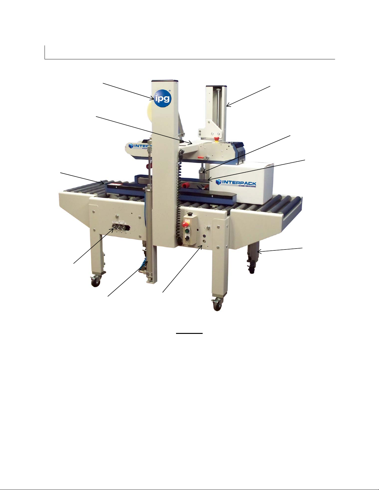
D
ESCRIPTION OF
RSA 2024-SB C
ASE SEALER
Drive Base
Assembly LH
USM0812
Column Assembly LH
USM1210
Bridge
Assembly
USM0816
Column Assembly RH
USM1208
Cylinder
Assembly RH
UAM0306
Drive Base
Assembly RH
USM0811
Leg Assembly
USM0817
Pneumatic
Assembly
USM6114
Cylinder
Assembly LH
UAM0305
Base Assembly
USM7563
Figure-1
The Interpack RSA 2024-SB Case Sealing Machine with HSD 2000-ET II Tape Heads
is designed to apply Intertape brand pressure sensitive case sealing tape to the top and
bottom center seam of regular slotted corrugated cases. The RSA 2024-SB is auto-
adjustable to a random variety of case sizes (see Case Specifications, Pg. 20)
UM122TW / UM622TW UDM10012
7

Important Safeguards
There are a number of safety labels used on Interpack Case Sealers. These labels are placed
at different locations (refer to Figure 2) on the machine to warn operators and service personnel
of possible dangers. Please read the labels on the machine and the following safety precautions
before using the machine.
Read this manual for other important safety operating and service information.
Only trained personnel are to operate machine.
Only fully qualified technicians are to service this machine.
Wear safety glasses.
Shut off power to machine before adjusting machine or loading & threading Tape
Heads.
Disconnect electrical power and compressed air (where applicable) before
servicing.
Follow Lock Out / Tag Out Procedures BEFORE servicing any machinery.
All covers and guards must be in place before operating.
Stay clear of moving parts which can shear and cut.
Never operate the Tape Heads with the Knife Guard removed.
Note: Should any of the safety labels placed on the Case Sealer be damaged or
destroyed, replacements are available through your distributor.
UM122TW / UM622TW UDM10012
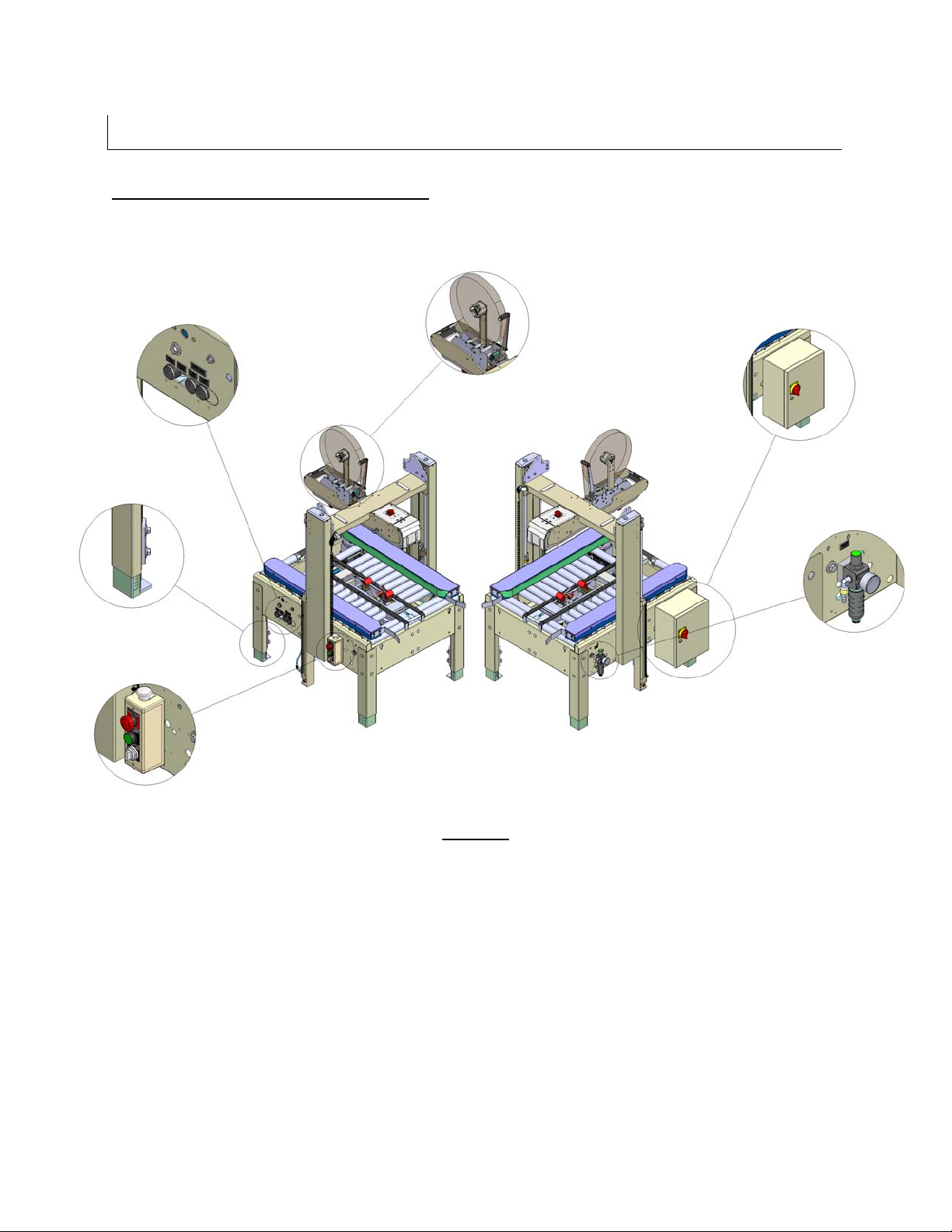
8
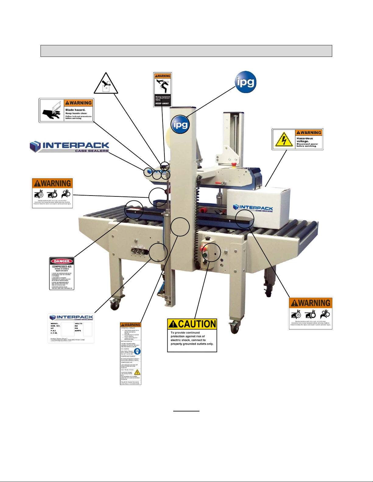
Important Safeguards
(Both Sides)
(Both Sides)
(Both Sides
If Installed)
(Located on
Tape Head)
(Also located on
Electrical Box)
Figure-2
(Both Sides)
(Located on
Electrical Box)
UM122TW / UM622TW UDM10012
9
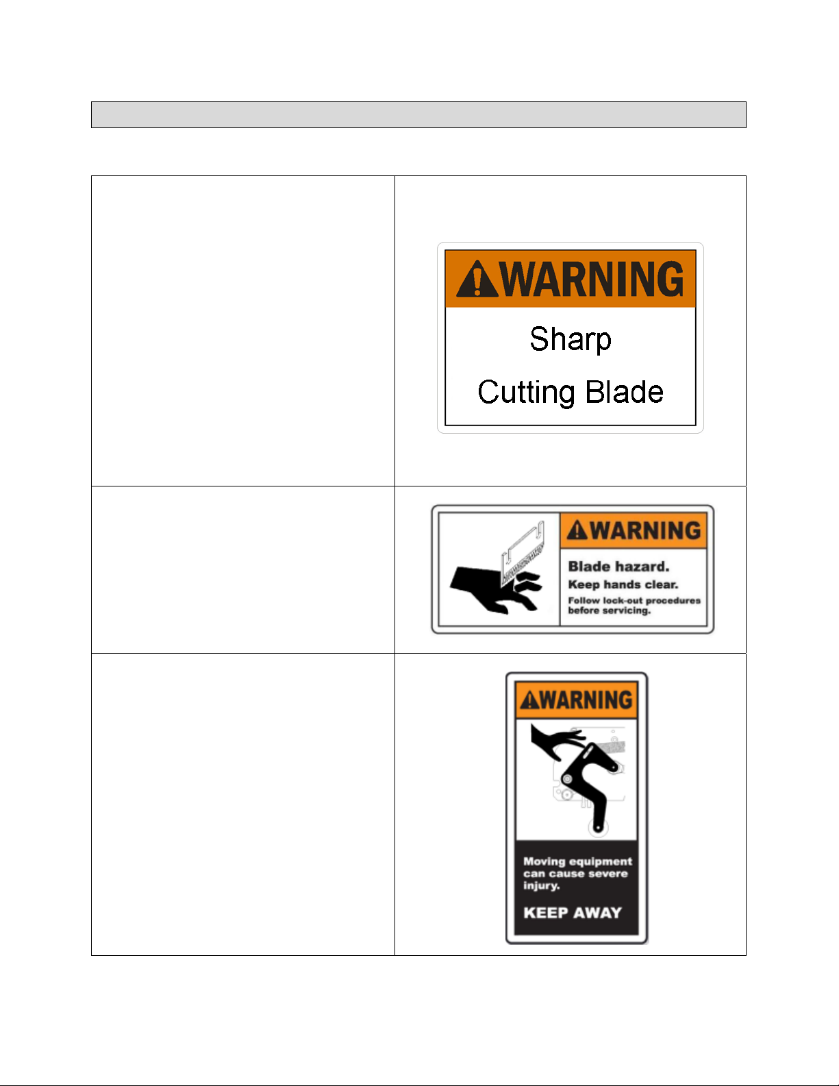
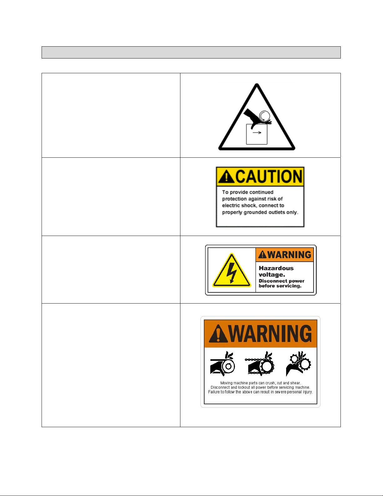
Important Safeguards
There Are A Number Of Safety Labels Used On Intertape Case Sealers.
The illustrated label as shown is attached
to the Knife Guard inside the upper and
lower HSD
label warns operators and service
personnel of the very sharp blade used to
cut the tape at the end of the tape
application.
The HSD
equipped with a Knife Guard that covers
the blade. The Tape Heads should never
be operated with the Knife Guards
removed.
Turn air and electrical supplies off before
servicing the tape heads.
2000-ET II Tape Head. The
2000-ET II Tape Heads are
The label shown is affixed to the upper
tape head assembly on either side of the
machine. It warns operators and service
personnel of the presence of the cutting
blade that may not be visible. Caution
should be exercised when approaching
this area.
The label shown (located on Tape Head)
alerts the operator of a potential pinch
point when a case processes through the
machine. Caution should be exercised
when approaching this area.
UM122TW / UM622TW UDM10012
10
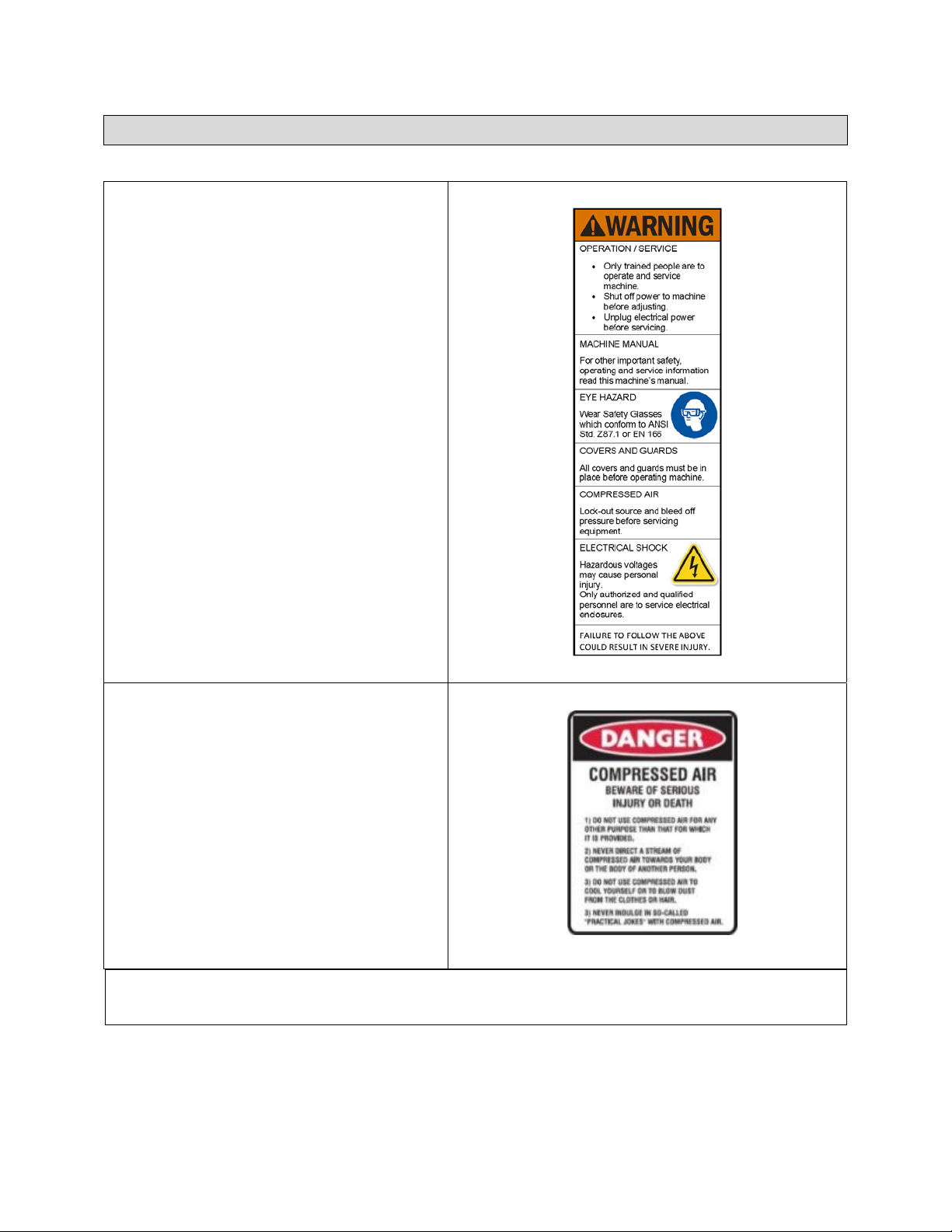
Important Safeguards
The label shown is affixed to the top
squeezer assembly brackets on either side
of the machine if installed. The squeezer
assembly is optional. They warn the
operator of a potential pinch point between
the top of the case and the top squeezer
rollers. Keep hand away from this area
when processing a case.
This label affixed to the electrical control
box and control box advises service
personnel to connect the machine to a
properly grounded outlet.
The label shown is attached to the
electrical control box. The label warns the
service personnel to unplug the power
supply before attempting any service work
on the case sealer.
The illustrated label shown is located on
the “infeed and exit” ends of the machine
belt drives. The label warns the operators
and service personnel of the pinch point at
each end of the belt drives.
UM122TW / UM622TW UDM10012
11
Important Safeguards
The illustrated label shown is located on
the side of the column. This label provides
convenient safety instructions for the
operator and service personnel in the
operation of the Intertape Case Sealing
Equipment.
This label advises personnel about the
dangers of the machine due to
compressed air used in the system. Be
aware of warnings and proper procedures
when running and/or servicing the
machine.
Note: Should any of the safety labels placed on the machine be da maged or destroyed,
replacements are available.
UM122TW / UM622TW UDM10012
12

Important Safeguards
Warning:
Indicates a potentially hazardous situation, which if not avoided could result in death, serious injury, or
property damage.
Caution:
Indicates a potentially hazardous situation, which if not avoided could result in minor or moderate injury,
or property damage.
To Reduce The Risk Associated With Mechanical And Electrical Hazards:
a. Read, understand, and follow all safety and operating instructions before operating or servicing
the case sealer.
b. Allow only properly trained and qualified personnel to operate and service this equipment.
To Reduce The Risk Associated With Pinches, Entanglement And Hazardous Voltage:
a. Turn electrical supply off and disconnect before performing any adjustments, maintenance, or
servicing the machine or tape heads.
To Reduce The Risk Associated With Pinches And Entanglement Hazards:
a. Do not leave the machine running while unattended.
b. Turn the machine off when not in use.
c. Never attempt to work on any part of the machine, load tape, or remove jammed boxes from the
machine while the machine is running.
To Reduce The Risk Associated With Hazardous Voltage:
a. Position electrical cord away from foot and vehicle traffic.
To Reduce The Risk Associated With Sharp Blade Hazards:
a. Keep hands and fingers away from tape cut-off blades under blade guards located on tape
heads. The blades are extremely sharp.
To Reduce The Risk Associated With Fire And Explosion Hazards:
a. Do not operate this equipment in potentially flammable/explosive environments.
To Reduce The Risk Associated With Muscle Strain:
a. Use the appropriate rigging and material handling equipment when lifting or repositioning this
equipment.
b. Use proper body mechanics when removing or installing taping heads that are moderately heavy
or may be considered awkward to lift.
To Reduce The Risk Associated With Pinch Hazards:
a. Keep hands clear of the upper head support assembly as boxes are transported through the
machine.
b. Keep hands, hair, loose clothing, and jewelry away from box compression rollers.
c. Always feed boxes into the machine by pushing only from the end of the box.
d.
Keep hands, hair, loose clothing, and jewelry away from moving belts and taping heads.
Explanation of Signal Word Consequences
Warning
Caution
UM122TW / UM622TW UDM10012
13

Important Safeguards
Warning
To Reduce The Risk Associated With Mechanical And Electrical Hazards:
a.
Allow only properly trained and qualified personnel to operate and service this equipment.
Operator Skill Level Descriptions
Skill “A”: Machine Operator
This operator is trained to use the machine with the machine controls, to feed cases into the
machine, make adjustments for different case sizes, to change the tape, and to start, stop, and
re-start production.
Important: The area supervisor must ensure that the operator has been properly
trained on all machine functions before operating the machine.
Skill “B” Mechanical Maintenance Technician
This technician is trained to use the machine as the machine operator and in addition is able to
work with the safety protection disconnected, to check and adjust mechanical components, to
perform maintenance operations, and repair the machine. He is not allowed to work on live
electrical components.
Skill “C” Electrical Maintenance Technician
This technician is trained to use the machine as the machine operator and in addition is able to
work with the safety protection disconnected, to check and adjust mechanical components, to
perform maintenance operations, and repair the machine. He is allowed to work on live
electrical panels, terminal blocks, and control equipment.
Skill “D” Manufacturers Technician
Skilled technicians sent by the manufacturer or its agent to perform complex repairs and
modifications, when agreed with the customer.
UM122TW / UM622TW UDM10012
14

Important Safeguards
Operators Skill Level Required To Perform The Following Tasks On The Machine
Operation Machine Condition
Machine Installation & Set Up
Adjusting Case Size
Tape Roll Replacement
Blade Replacement Electrical Power Disconnected B 1
Drive Belt Replacement Electrical Power Disconnected B 1
Ordinary Maintenance Electrical Power Disconnected B 1
Running With Safety Protections
Disabled
Stopped By Pressing The
Emergency Stop Button
Stopped By Pressing The
Emergency Stop Button
Operator Skill
Level
B & C 2
A 1
A 1
Number Of
Operators
Extraordinary Mechanical
Maintenance
Extraordinary Electrical
Maintenance
Running With Safety Protections
Disabled
Running With Safety Protections
Disabled
D 1
C 1
UM122TW / UM622TW UDM10012
15

SPECIFICATIONS
RSA 2024-SB Machine Dimensions
Figure-3
Machine Weight:
650 lbs. (295 kg) crated
UM122TW / UM622TW UDM10012
16
SPECIFICATIONS
RSA 2024-SB Machine Components
Balance/Drive
Base/Compression
Guide Regulators
Conveyer Height
Adjustment
Control Box
See Section 7, Page 30 In This
Manual For Tape Loading &
Tape Head
Threading.
Figure-4
Electrical Box
Main Air
Regulator
UM122TW / UM622TW UDM10012
17

SPECIFICATIONS
1. Operating Conditions
Use in a dry, relatively clean environment at 40° to 105° F (5° to 40° C) with clean dry cases.
Note: Machine should not be washed down or subjected to conditions
causing condensation on components.
2. Power Requirements
Electrical - 110 VAC, 60 HZ, 6 A
Compressed Air – 9 CFM @ 90 PSI
This machine comes standard with two gear motors, one on each drive base, a control box, and
an electrical box.
The control box contains a Start switch, an Emergency Stop switch, a “Clear” push button, an
Operation Selection switch. A twelve foot (12’) standard three conductor power cord with plug
is provided for 110V, 60HZ, 15 Amp service. The receptacle providing this service must be
properly grounded.
3. Operating Speed
Actual production rate is dependent on operator’s dexterity and the case size mix. Belt Speed is
82 Ft/min.
UM122TW / UM622TW UDM10012
18

SPECIFICATIONS
4. Tape Specifications
Use Intertape Brand Pressure Sensitive Case Sealing Tape.
The machine can accommodate 2” (48mm) or 3” (72mm) wide tape, depending on tape heads
supplied.
A maximum tape roll diameter of 16” (406 mm) on a 3” (76 mm) diameter core can be installed
on the tape head. (Accommodates all Intertape brand film tape machine roll lengths).
The standard Tape Leg Length of 2.25 inches (57.2 mm) is factory set. The standard tape leg
length may vary up to ¼” (6mm) based on tape tension and line speed.
The standard tape leg length is adjustable +/- ¼. Refer to the tape head manual for adjustment
of tape leg length.
Note: For further specifications on the tape heads, consult the tape head
manual for your specific tape head.
UM122TW / UM622TW UDM10012
19

SPECIFICATIONS
5. Case Specifications
Type
Regular Slotted Containers (RSC)
Other style cases may be processed, consult factory for details.
Material
125 To 275 PSI Bursting Test, Single Or Double Wall B Or C Flutes.
Weight
0 to 85 lbs. (0 to 38.5 kg)
Size
The case sealer can accommodate most cases within the size ranges listed below.
Standard
Case Size Length Width Height
Minimum
Maximum
152mm
6”
Infinite 508mm
101mm
4”
20”
88mm
3.5”
609mm
24”
Optional
Case Size Length Width Height
Minimum
Maximum
203mm
8”
Infinite 508mm
203mm
8”
20”
50mm
2”
609mm
24”
Note: See Page 21 for set up procedure for running cases in the “Optional” size.
UM122TW / UM622TW UDM10012
20
S
PECIFICATIONS
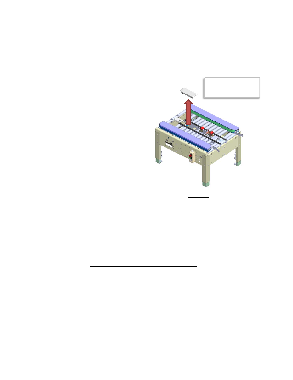
“Optional” Case Size
To run cases with sizes that fall within the
parameters set in the “Optional” Case Size
chart in Page 20, remove the rear bottom
gap filler as shown in Figure-5.
Top Tape Head Box
Assembly Removed For
Clarity.
Figure-5
Case Processing Stability
For optimal performance, the cases should be stable when processing through the machine.
Unstable cases may tilt backwards upon contact with the upper tape head causing the machine
to jam.
If the box length (in direction of seal) to box height ratio is .75 or less, then several boxes should
be test run to assure proper machine performance. The formula is as follows;
CASE LENGTH IN DIRECTION OF SEAL > .75
CASE HEIGHT
UM122TW / UM622TW UDM10012
21
SET-UP PROCEDURES
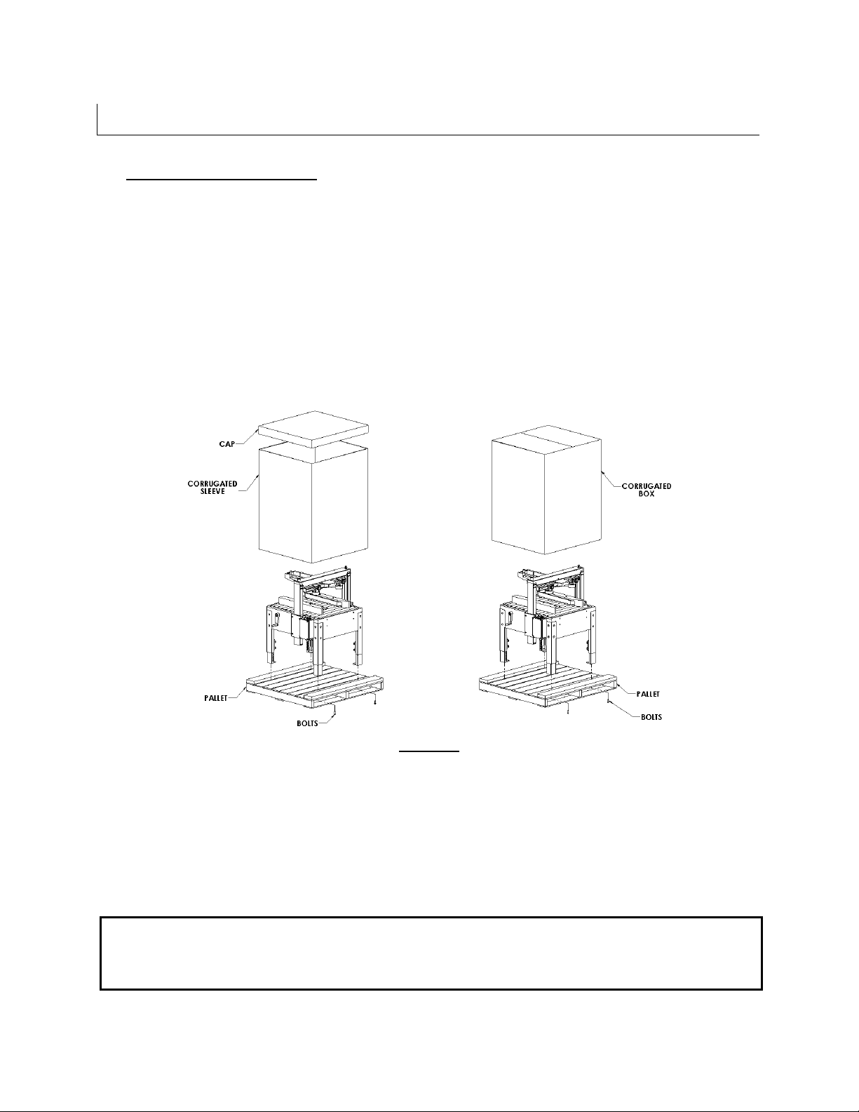
1. Receiving and Handling
The machine is shipped to the customer fixed to a pallet. The machine is enclosed with either a
corrugated sleeve and cap or an HSC corrugated box. The sequence below is step by step
instructions to remove all packing materials.
Remove the strapping securing the corrugated sleeve and cap or HSC corrugated box to
the pallet.
Lift off the cap and corrugated sleeve or HSC corrugated box.
Remove protective wrapping from machine.
Remove or relocate all securing devices such as tie wraps or locking collars.
Remove the mounting bolts, which secure the machine to the shipping pallet.
Remove machine from the pallet and re-locate to an area to prepare for final installation.
Figure-6
All contents must be verified upon reception. The following items are included with each
machine.
RSA 2024-SB
Operators Manual Machine
Operators Manual Tape Head
Plastic bag containing tape head spare parts.
Note: After unpacking the case sealer, look for any damage that may have occurred
during shipping. Should the case sealer be damaged, file a claim with the
transport company and notify your authorized Intertape distributor.
UM122TW / UM622TW UDM10012
22
SET-UP PROCEDURES
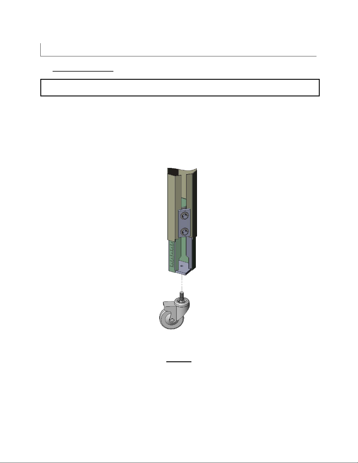
2. Caster Installation (If Purchased)
Caster installation requires raising the machine to access the bottom of each leg. Please
follow all possible safety procedures prior to and during this process.
A. With a fork lift, raise the machine to allow access to the bottom of each leg.
B. Screw in a caster into a leg until it is firmly seated to the bottom of the leg.
C. Tighten each caster.
D. Do not adjust the conveyor height by adjusting the caster. Proper conveyor height
must be achieved by adjusting the leg extension of each leg.(See Figure-8)
Figure-7
UM122TW / UM622TW UDM10012
23
SET-UP PROCEDURES
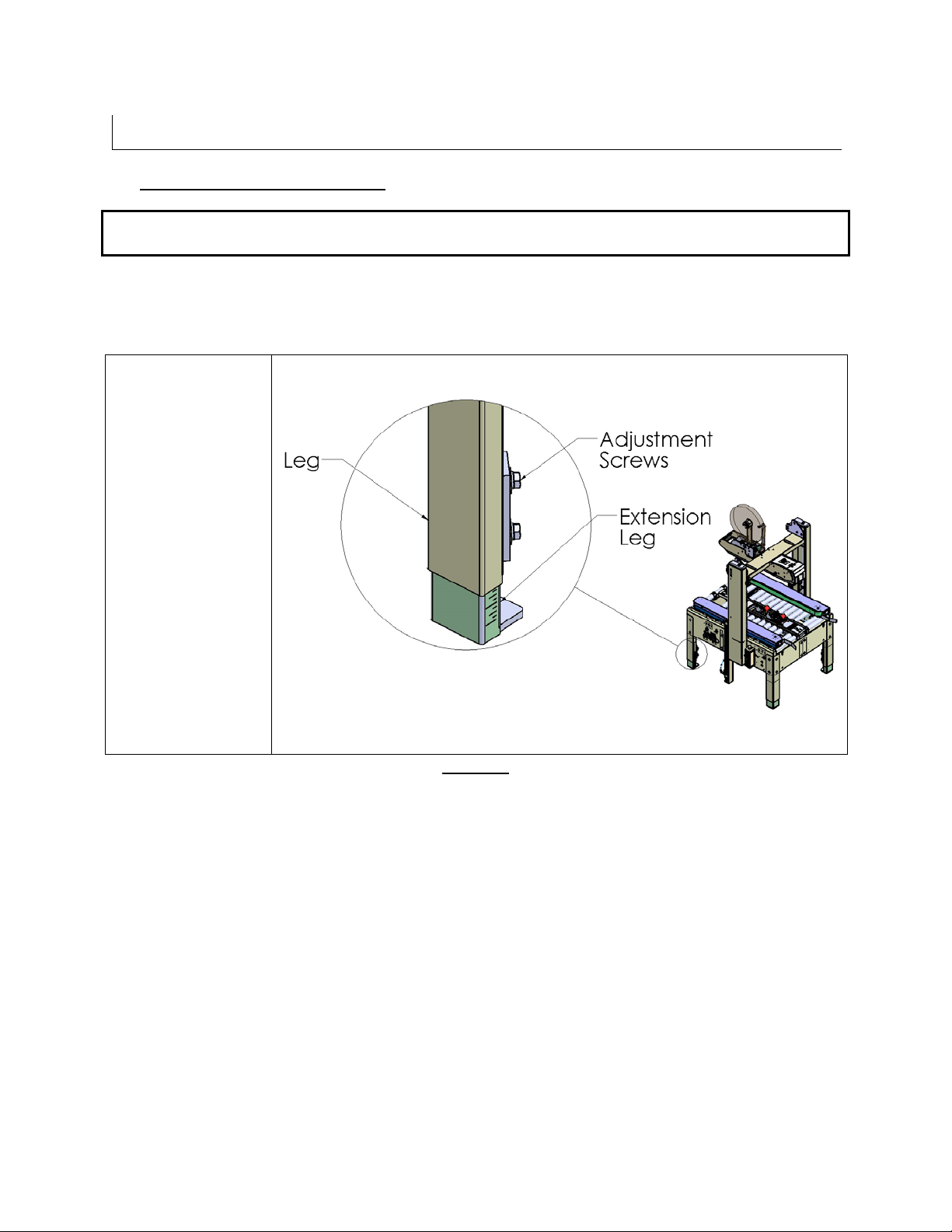
3. Machine Height Adjustment
Machine height adjustment requires raising the machine to adjust each leg. Please follow
all possible safety procedures prior to and during this process.
The Case Sealer must be level when installed. Use the adjustable legs to ensure that the
machine is level and firmly on the ground (no rocking). Adjust the leg height with the four (4)
telescopic extension legs to accommodate conveyor heights from 24 to 30 inches.
To adjust the Case
Sealer height, lift
the machine to give
ample room to
extend the legs.
Using a 19 mm box
end wrench, loosen
the eight (8) 12mm
hex head bolts.
Adjust the legs to
the desired
conveyor height
and re-tighten the
bolts. Etched lines
on the legs ease
leveling.
Figure-8
UM122TW / UM622TW UDM10012
24

SET-UP PROCEDURES
4. Installation of Interpack Brand In-Feed and Exit Roller Tables (If Purchased)
Case Direction
Figure-9A
a. Install two (2) mounting studs into roller table with hardware included. Per
b. Utilizing the slots on the machine base, attach roller table to machine base by locating
mounting studs in slots on machine base and push down to lock in place. Per
9B.
c. Once roller table is attached to the machine base using the two mounting studs, install
remaining two (2) mounting studs with hardware included through the bottom two holes
on the machine base and roller table. Per Figure-9C.
d. After all four (4) mounting studs and included hardware have been installed, tighten all
hardware to avoid roller table instability then install rollers on to table.
Figure-9B
Figure-9C
Figure-9A.
Figure-
UM122TW / UM622TW UDM10012
25
r
SET-UP PROCEDURES
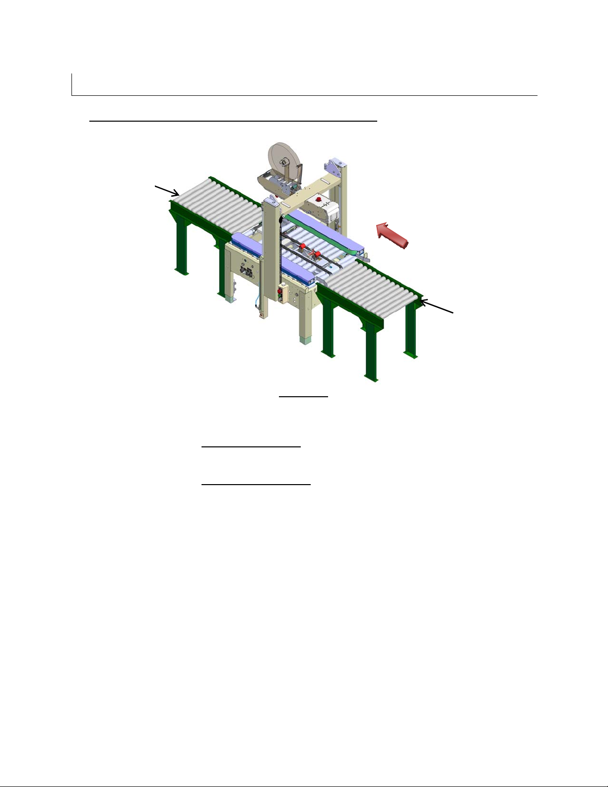
Installation of External In-Feed and Exit Conveyors
5.
Exit Conveyo
Case Direction
In Feed Conveyor
Figure-10
1. Customer supplied in-feed conveyor (if used) should provide straight (not curved) and
level entry into the case sealer.
2. Customer supplied gravity exit conveyor (if used) should be straight (not curved) and a
downward pitch of at least ¼ inch per foot away from the machine to convey the sealed
cases away from the machine.
3. Customer supplied powered exit conveyor should be straight (not curved) and level to
convey the sealed cases away from the machine.
UM122TW / UM622TW UDM10012
26
SET-UP PROCEDURES
6. Connecting Utilities
a. Electrical
Figure-11
Figure-12
A twelve foot (12’) standard three conductor power cord with plug is provided for 110V, 60 Hz,
15 amp electrical service. The receptacle must be properly grounded. Before the machine is
plugged into the receptacle, ensure that all materials are removed from the machine. The
electrical control is protected with an automatic circuit breaker with resettable overload.
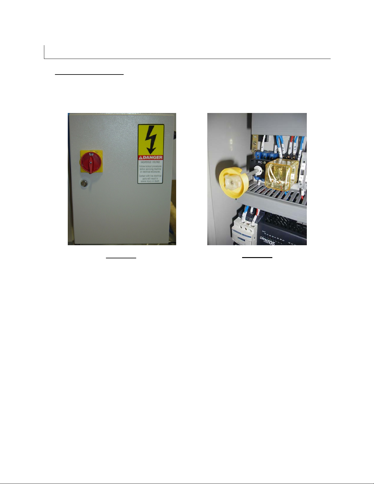
The electrical control box (Figure-11) is located on the side of the Case Sealer for
customer convenience. The Electric Box contains a Power Switch Disconnect to prevent
the use of the machine during maintenance. The machine will not start unless the Power
Switch Disconnect is turned to “ON”. To open the electric Box, turn the Power Switch to
the “OFF” position, and use a slotted screwdriver and turn it clockwise to open the door.
When opening the door of the electrical box, the door handle should stay in the electrical
box disconnect switch (Figure-12). In order to close the electrical box door again, align
the switch arm with the handle in the door.
UM122TW / UM622TW UDM10012
27
SET-UP PROCEDURES
6. Connecting Utilities, cont’d.
a. Electrical, cont’d.
Figure-13
Figure-14
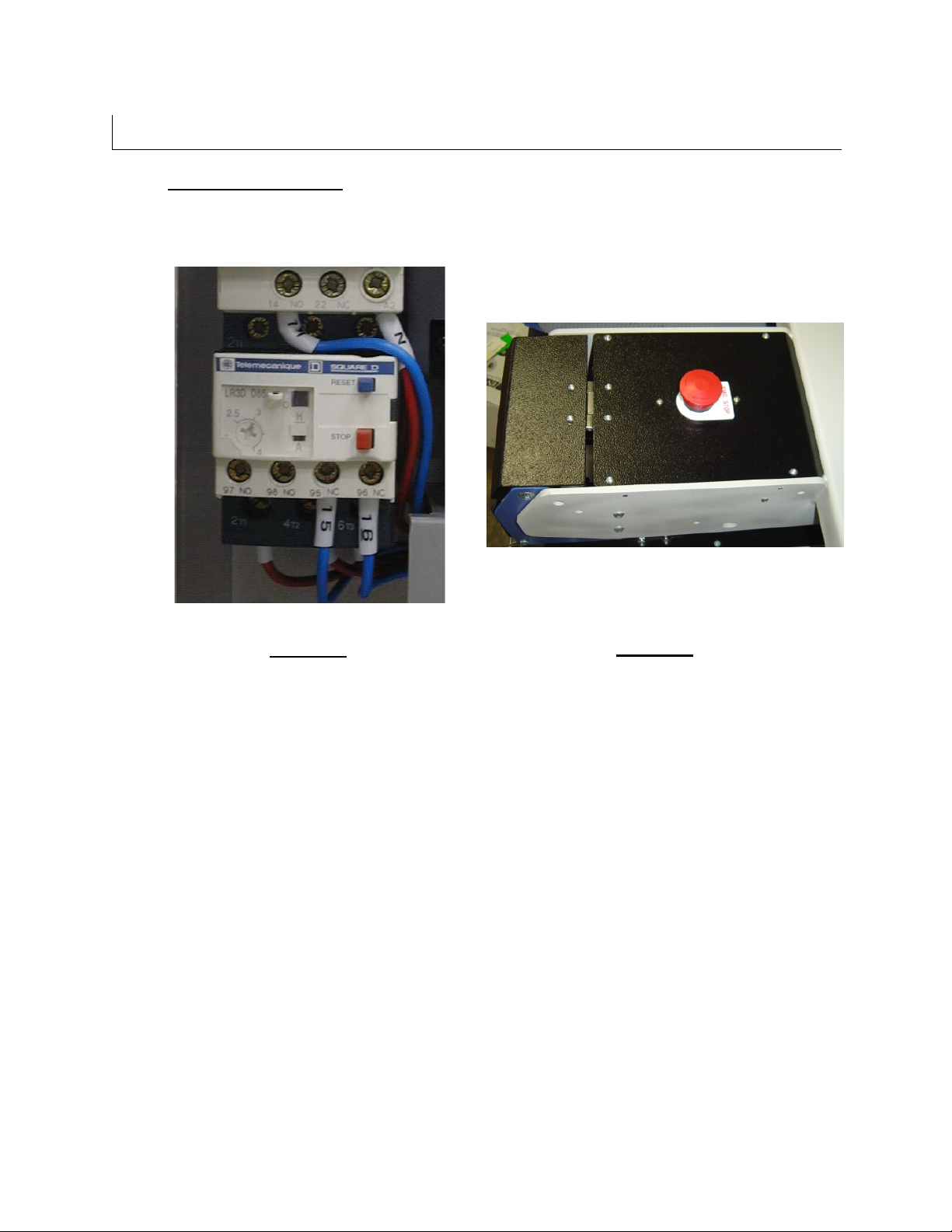
The electric motors are protected with an automatic re-settable overload (Figure-13). This reset
is located in the electrical box in the lower left quadrant. Push on the top blue button to reset.
The current setting should be set at 110% of the FLA (Full Load Amps) of a single motor.
There is an E-Stop button for the case sealer located on the Top Tape Head Box (Figure-14).
The other E-Stop button is located on the control box of the case sealer (Refer to Page 35,
Figure 26).
UM122TW / UM622TW UDM10012
28
SET-UP P
ROCEDURES
7. Connecting Utilities, cont’d.
b. Pneumatic
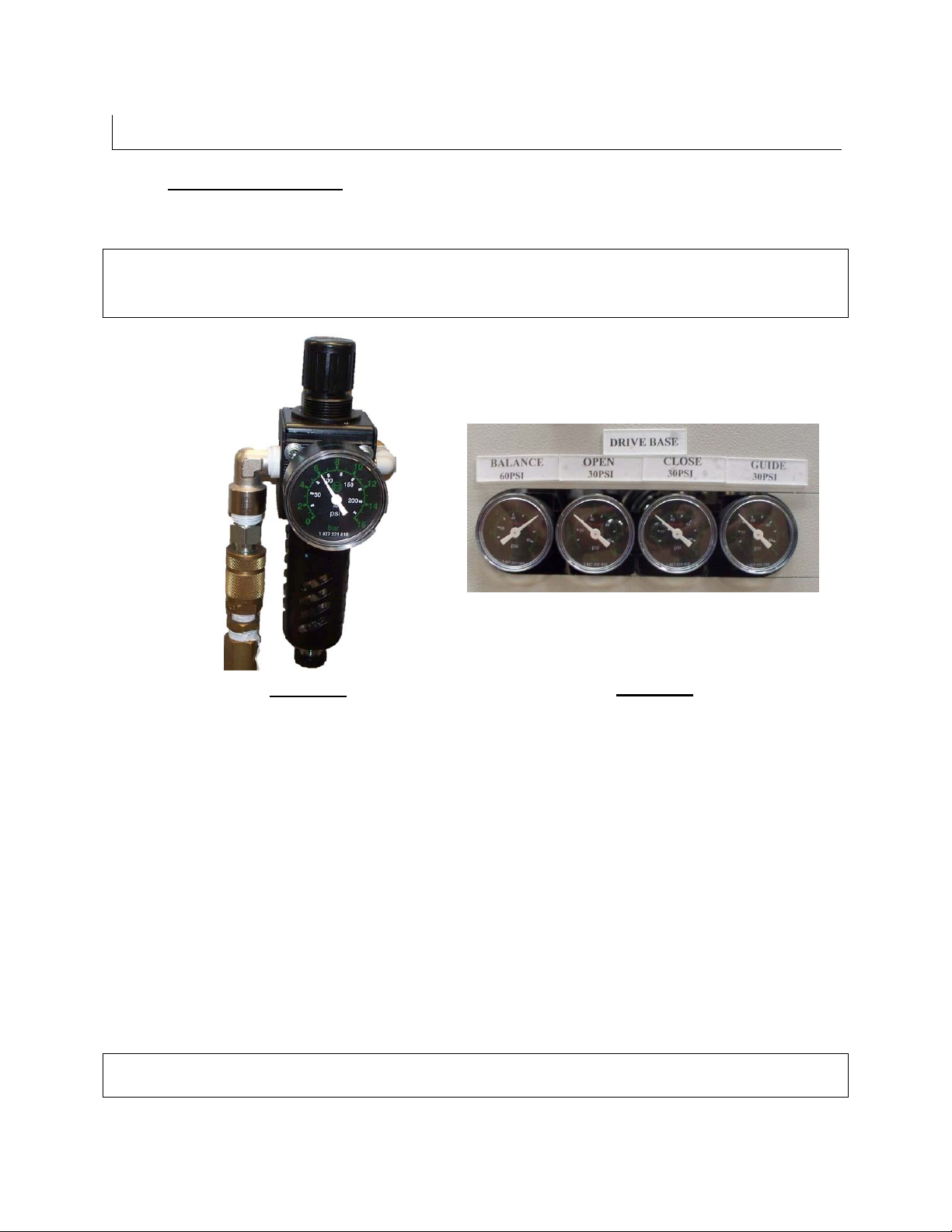
Note: The pressure setting for the air regulators (Figure-15 & Figure-16) are
factory set. These values will need to be adjusted as needed by customer
supplied pressure and volume.
Figure-15
Figure-16
The main air regulator (Figure-15) has a male "quick disconnect" adaptor. Connect clean dry
compressed air to this adaptor. The RSA2024-SB requires a minimum of 9 CFM at 90 PSI.
To regulate the main air pressure, pull on the knob located on the top of the main air
regulator (Figure-15). Turn the knob clockwise for more pressure and counterclockwise
for less. When the air pressure is at 90 PSI, push back down on the button until a "click"
is felt to lock it in position. The thread size is 3/8 NPT.
The pressure regulators in Figure-16 control various operations of the machine. The regulator
on the left side labeled “BALANCE” controls the balance pressure for the top tape head box.
The recommended pressure setting for the “BALANCE” regulator is 60PSI. The regulators on
the center labeled “OPEN” and “CLOSE” control the pressure for the drive bases. The
recommended pressure settings for the “OPEN” and “CLOSE” regulators is 30PSI. The
regulator on the right side labeled “GUIDE” controls the pressure for the compression guides.
The compression guides are optional and the “GUIDE” regulator will be included if the machine
option is installed. The recommended pressure setting for the “GUIDE” regulator is 30PSI.
Note: Should the supplied airline or pressure be unplugged or cut for any reason, the
Top Tape Head Box will retain its current position until the compressed air is restored.
UM122TW / UM622TW UDM10012
29
SET-UP P
ROCEDURES
8. Removing Tape Heads Prior to Tape Loading
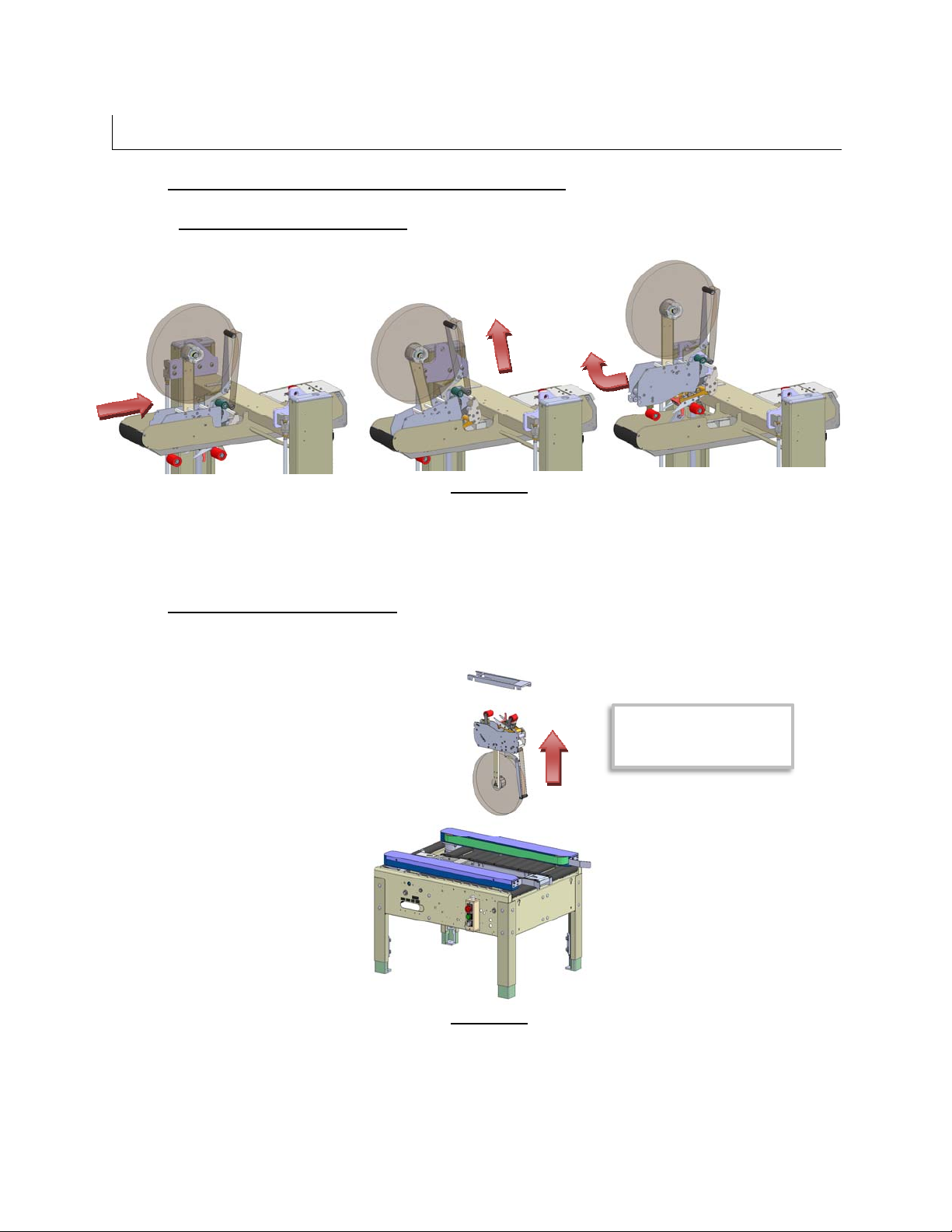
Removing Upper Tape Head
Figure-17
1. Slide Tape Head Toward The Infeed End Of Machine And Rotate Up.
2. Slide Tape Head Toward The Exit End Of Machine And Lift Out Of Rear Slot.
Removing Lower Tape Head
Top Tape Head Box
Assembly Removed For
Clarity.
Figure-18
1. Remove Gap Filler (included in 2” model only) by Lifting Straight Up.
2. Gripping the Stationary Cross Shafts, Lift the Tape Head Straight Up and Out of The
Slots.
UM122TW / UM622TW UDM10012
30
 Loading...