

IPEX VXE Installation Manual
VXE Series Ball Valves
Installation Procedures
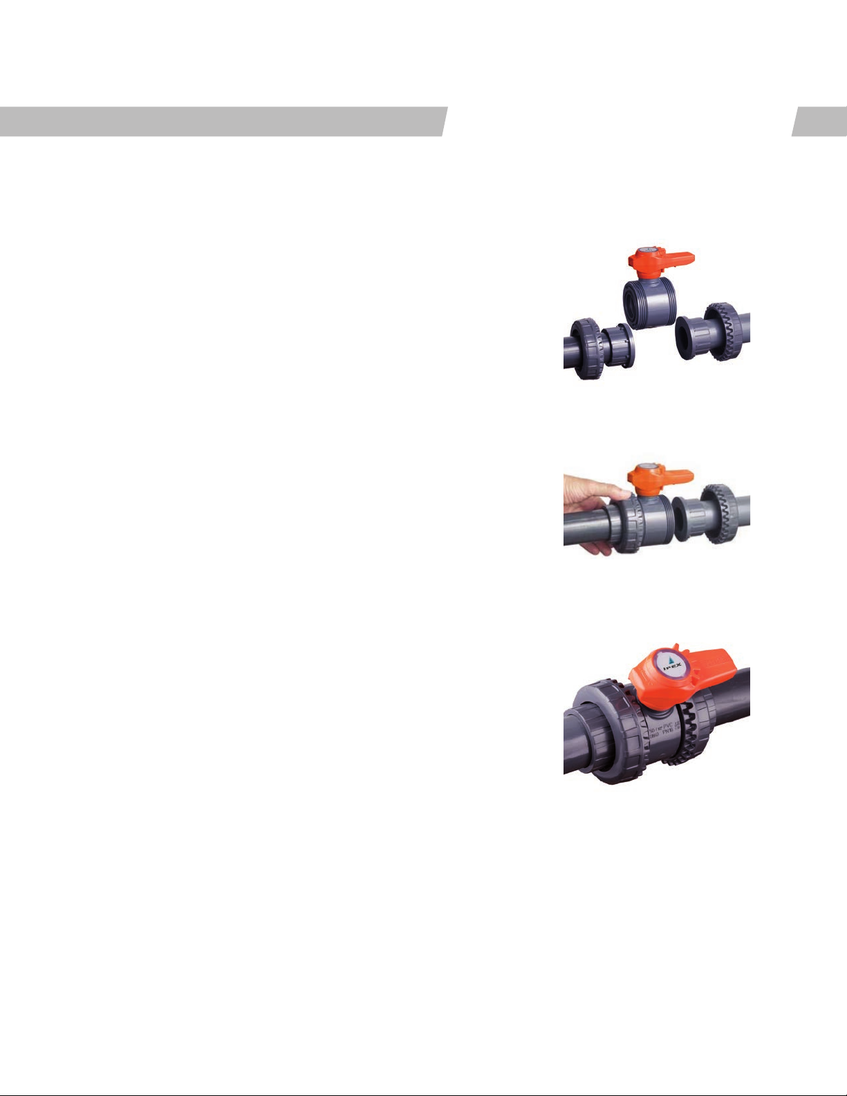
1. For socket and threaded style connections, remove the union nuts
(part #13 on previous page) and slide them onto the pipe. For flanged
connections, remove the union nut / flange assemblies from the valve.
2. Please refer to the appropriate connection style sub-section:
a. For socket style, solvent cement the end connectors (7 or 12) onto the
pipe ends. For correct joining procedure, please refer to the section
entitled, “Joining Methods – Solvent Cementing” in the IPEX Industrial
Technical Manual Series, “Volume I: Vinyl Process Piping Systems”.
Be sure to allow sucient cure time before continuing with the
valve installation.
b. For threaded style, thread the end connectors (7) onto the pipe ends.
For correct joining procedure, please refer to the section entitled,
“Joining Methods – Threading” in the IPEX Industrial Technical
Manual Series, “Volume I: Vinyl Process Piping Systems”.
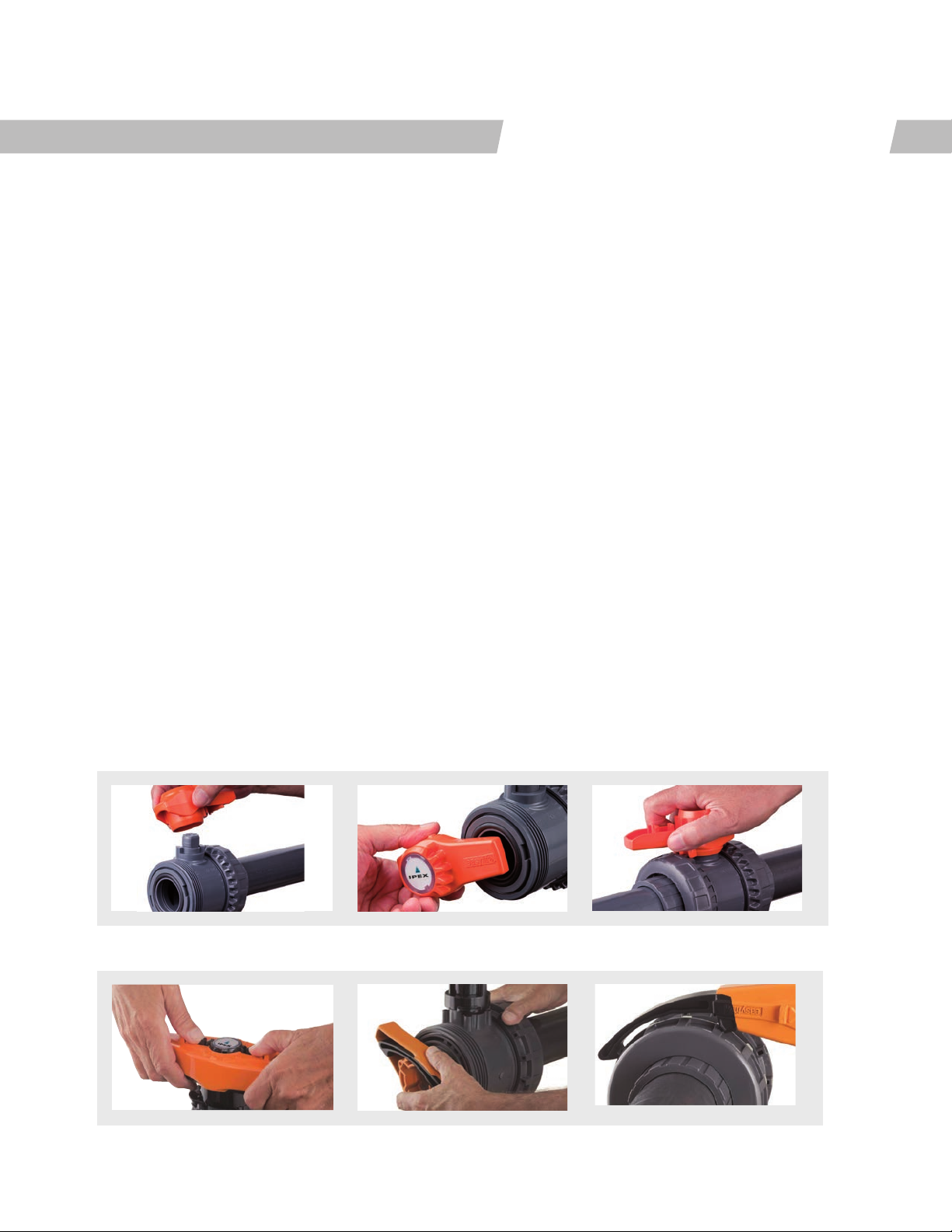
Submittal Data Sheet
3. Open and close the valve to ensure that the ball seat support (8) is at the
desired adjustment. If adjustment is required, ensure that the valve is in
the closed position then remove the handle (12 or 2) from the valve stem.
Line up the moldings on the handle wit the slots in the ball seat support.
Tighten or loosen to the desired position then replace the handle on the
valve stem.
4. Ensure that the valve is in the closed position, and that the socket o-rings
(10) are properly fitted in their grooves. Carefully place the valve in the
system between the two end connections.
5. Tighten the union nut on the side opposite to that which is marked
“ADJUST”. Hand tightening is typically sucient to maintain a seal for the
maximum working pressure. If additional tightening is required, the Easyfit
multifunctional handle tool can be used to tighten the union nuts an
additional 1/4 turn.
6. Tighten the union nut on the side marked “ADJUST”. Tightening the union
nuts in this order results in the best possible valve performance due to
optimum positioning and sealing of the ball and seat support system.
Over-tightening may damage the threads on the valve body and/
or the union nut and may even cause the union nut to crack. It is
recommended to use the Easyfit handle to prevent damage.
7. Open and close the valve to again ensure that the cycling performance is
adequate. If adjustment is required, place the valve in the closed position,
loosen the union nuts, remove the valve from system and then continue
from Step 3.
6
VXE Series Ball Valves
Valve Maintenance
Disassembly
Submittal Data Sheet
1. If removing the valve from an operating system, isolate
the valve from the rest of the system. Be sure to
depressurize and drain the isolated branch and valve
before continuing.
2. Loosen both union nuts (13) and drop the valve out of
the line. If retaining the socket o-rings (10), take care
that they are not lost when removing the valve from
the line.
a. For 1/2” to 2” remove the handle (12) and the
transparent service plug (1a). Turn handle over,
and seat on valve stem, ensuring the integrated
gear teeth on the handle mesh with the union nut
teeth. Turn clockwise to loosen.
b. For 2-1/2” to 6” remove handle (2). Remove the
Easyfit multifunctional tool (1) from the bottom
of the handle (2), turn it over and re-install it.
Engage the tool (1) with the outer ring profile on
the union nut (13) and loosen.
3. To disassemble, place the valve in the closed position
and locate the ball seat support adjustment tool on
the multifunctional handle. This is found on the bottom
of 1/2” to 2” handles and on the top of 2-1/2” to 6”
handles.
4. Line up the moldings on the handle with the slots
in the ball seat support (found on the side marked
“ADJUST”). Loosen and remove the ball seat support
(8 or 11) by turning in a counterclockwise direction.
5. Carefully press the ball (5 or 6) out of the valve body,
taking care not to score or damage the outer surface.
6. To remove the stem (3 or 4), remove the central hub
(15) on 2-1/2” to 6” sizes, press the stem into the valve
body (4 or 7) from above.
7. The stem o-rings (2 or 3), body o-ring (6 or 9), friction
reducing bushing (16) and ball seats (9 or 5) can now
be removed and/or replaced.
1/2” – 2” VXE Ball Valves
2-1/2” – 6” VXE Ball Valves
7
 Loading...