

Page 1

Volume XI:
Thermoplastic
Valves
Industrial Technical
Manual Series
FIRST EDITION
IPEX THERMOPLASTIC VALVES
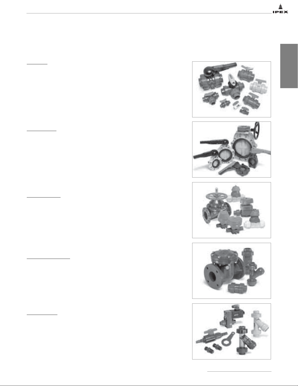
• Ball Valves
• Butterfly Valves
• Diaphragm Valves
• Check and Vent Valves
• Specialty Valves
Page 2

Thermoplastic Valves
Industrial Technical Manual Series
Vol. XI, 1st Edition
© 2008 by IPEX. All rights reserved. No part of this book may
be used or reproduced in any manner whatsoever without prior
written permission. For information contact: IPEX, Marketing, 2441
Royal Windsor Drive, Mississauga, Ontario, Canada, L5J 4C7.
The information contained here within is based on current
information and product design at the time of publication and is
subject to change without notification. IPEX does not guarantee or
warranty the accuracy, suitability for particular applications, or
results to be obtained therefrom.
Page 3
ABOUT IPEX
At IPEX, we have been manufacturing non-metallic pipe and fittings since 1951. We formulate our own compounds and
maintain strict quality control during production. Our products are made available for customers thanks to a network of
regional stocking locations throughout North America. We offer a wide variety of systems including complete lines of piping,
fittings, valves and custom-fabricated items.
More importantly, we are committed to meeting our customers’ needs. As a leader in the plastic piping industry, IPEX
continually develops new products, modernizes manufacturing facilities and acquires innovative process technology. In addition,
our staff take pride in their work, making available to customers their extensive thermoplastic knowledge and field experience.
IPEX personnel are committed to improving the safety, reliability and performance of thermoplastic materials. We are involved in
several standards committees and are members of and/or comply with the organizations listed on this page.
For specific details about any IPEX product, contact our customer service department.
Page 4
SAFETY ALERTS
Engineered thermoplastics are safe inert materials that do not pose any significant safety or environmental hazards during
handling or installation. However, improper installation or use can result in personal injury and/or property damage. It is
important to be aware of and recognize safety alert messages as they appear in this manual.
The types of safety alert messages are described below.
This safety alert symbol indicates important safety messages in
this manual. When you see this symbol be alert to the possibility
of personal injury and carefully read and fully understand the
message that follows.
WARNING
“WARNING” identifies hazards or unsafe practices that
can result in severe personal injury or death if
instructions, including recommended precautions, are
not followed.
Note: The use of the word “NOTE” signifies special instructions which are
important but are not related to hazards.
For the materials described in this manual, the following warming applies.
“CAUTION” identifies hazards or unsafe practices that
can result in minor personal injury or product or
property damage if instructions, including
recommended precautions, are not followed.
WARNING
• NEVER use compressed air or gas in PVC/CPVC/PP/PVDF
pipe and fittings.
• NEVER test PVC/CPVC/PP/PVDF pipe and fittings with
compressed air or gas, or air-over-water boosters.
• ONLY use PVC/CPVC/PP/PVDF pipe for water and
approved chemicals.
CAUTION
Use of compressed air or gas in PVC/CPVC/PP/PVDF pipe
and fittings can result in explosive failures and cause severe
injury or death.
IPEX Thermoplastic Valves
i
Page 5

NOTES
______________________________________________________
______________________________________________________
______________________________________________________
______________________________________________________
______________________________________________________
______________________________________________________
______________________________________________________
______________________________________________________
______________________________________________________
______________________________________________________
______________________________________________________
______________________________________________________
______________________________________________________
______________________________________________________
______________________________________________________
______________________________________________________
______________________________________________________
______________________________________________________
______________________________________________________
______________________________________________________
______________________________________________________
______________________________________________________
______________________________________________________
______________________________________________________
______________________________________________________
______________________________________________________
______________________________________________________
______________________________________________________
______________________________________________________
______________________________________________________
______________________________________________________
______________________________________________________
______________________________________________________
______________________________________________________
______________________________________________________
ii
IPEX Thermoplastic Valves
Page 6

CONTENTS
Thermoplastic Valves Manual
About IPEX
Safety Alerts . . . . . . . . . . . . . . . . . . . . . . . . . . . . . . . . . . . . . . . . . . . . . . . . .i
Section One: General Information
Overview . . . . . . . . . . . . . . . . . . . . . . . . . . . . . . . . . . . . . . . . . . . . . . . . . . .1
Features and Benefits . . . . . . . . . . . . . . . . . . . . . . . . . . . . . . . . . . . . . . . . . .2
Applications . . . . . . . . . . . . . . . . . . . . . . . . . . . . . . . . . . . . . . . . . . . . . . . . .3
Material Description . . . . . . . . . . . . . . . . . . . . . . . . . . . . . . . . . . . . . . . . . . .4
Valve Types . . . . . . . . . . . . . . . . . . . . . . . . . . . . . . . . . . . . . . . . . . . . . . . . .5
Valve Selection . . . . . . . . . . . . . . . . . . . . . . . . . . . . . . . . . . . . . . . . . . . . . . .7
Further Information . . . . . . . . . . . . . . . . . . . . . . . . . . . . . . . . . . . . . . . . . . . .8
Section Two: Ball Valves
VKD Series Ball Valves . . . . . . . . . . . . . . . . . . . . . . . . . . . . . . . . . . . . . . . . .9
VX Series Ball Valves . . . . . . . . . . . . . . . . . . . . . . . . . . . . . . . . . . . . . . . . .18
VE Series Ball Valves . . . . . . . . . . . . . . . . . . . . . . . . . . . . . . . . . . . . . . . . .25
MP Series Compact Ball Valves . . . . . . . . . . . . . . . . . . . . . . . . . . . . . . . . . .31
TK Series 3-Way Ball Valves . . . . . . . . . . . . . . . . . . . . . . . . . . . . . . . . . . . .35
TKD Series 3-Way Ball Valves . . . . . . . . . . . . . . . . . . . . . . . . . . . . . . . . . . .45
VT Series 3-Way Ball Valves . . . . . . . . . . . . . . . . . . . . . . . . . . . . . . . . . . . . .55
Section Three: Butterfly Valves
FK Series Butterfly Valves . . . . . . . . . . . . . . . . . . . . . . . . . . . . . . . . . . . . . .65
FE Series Butterfly Valves . . . . . . . . . . . . . . . . . . . . . . . . . . . . . . . . . . . . . .75
Section Four: Diaphragm Valves
VM Series Manual Diaphragm Valves . . . . . . . . . . . . . . . . . . . . . . . . . . . . . .85
VM Series Pneumatic Diaphragm Valves . . . . . . . . . . . . . . . . . . . . . . . . . . . .93
DV Series Diaphragm Valves . . . . . . . . . . . . . . . . . . . . . . . . . . . . . . . . . . .105
CM Series Compact Diaphragm Valves . . . . . . . . . . . . . . . . . . . . . . . . . . . .111
DM Series Diaphragm Valves . . . . . . . . . . . . . . . . . . . . . . . . . . . . . . . . . . .122
IPEX Thermoplastic Valves
iii
Page 7

Section Five: Check and Vent Valves
VB Series Ball Check Valves . . . . . . . . . . . . . . . . . . . . . . . . . . . . . . . . . . .129
VR Series Piston Check Valves . . . . . . . . . . . . . . . . . . . . . . . . . . . . . . . . . .134
SC Series Swing Check Valves . . . . . . . . . . . . . . . . . . . . . . . . . . . . . . . . . .145
VA Series Air Release Valves . . . . . . . . . . . . . . . . . . . . . . . . . . . . . . . . . . .150
Section Six: Specialty Valves
RV Series Sediment Strainers . . . . . . . . . . . . . . . . . . . . . . . . . . . . . . . . . .155
SF Series Solenoid Valves . . . . . . . . . . . . . . . . . . . . . . . . . . . . . . . . . . . . .165
LV Series Lab Valves . . . . . . . . . . . . . . . . . . . . . . . . . . . . . . . . . . . . . . . . .171
Section Seven: Standards
Standards Organizations . . . . . . . . . . . . . . . . . . . . . . . . . . . . . . . . . . . . . .175
Applicable Standards . . . . . . . . . . . . . . . . . . . . . . . . . . . . . . . . . . . . . . . .175
Valve Application Assistance Form
iv
IPEX Thermoplastic Valves
Page 8

SECTION ONE: GENERAL INFORMATION
OVERVIEW
This manual provides the most up-to-date and comprehensive information about IPEX valves. Written with the needs of the
engineer and contractor in mind, all aspects of our valves are covered. This includes material properties, specifications, valve
types and selection, installation, as well as testing and operating considerations.
With more than 50 years of design and manufacturing experience, these lightweight, long life and maintenance free valves
save both time and money. Our high-tech automated manufacturing and testing facility ensures unparalleled reliability for
each and every valve.
IPEX quality engineered products include many unique characteristics ranging from important safety features, to simple
ergonomic and aesthetic benefits. Material options such as PVC, CPVC, PP, PVDF, and ABS make our corrosion resistant
valves ideal for use in a wide variety of demanding applications.
IPEX thermoplastic valves are part of our complete systems of pipe, valves, and fittings, engineered and manufactured to our
strict quality, performance, and dimensional standards. Our network of manufacturing and customer service facilities across
North America ensures fast, reliable service, and expert technical support.
INFORMATION
GENERAL
IPEX Thermoplastic Valves
CAUTION: Do not use or test the products in this manual with compressed air or other gases including air-over-water-boosters.
1
Page 9
GENERAL
INFORMATION
FEATURES AND BENEFITS
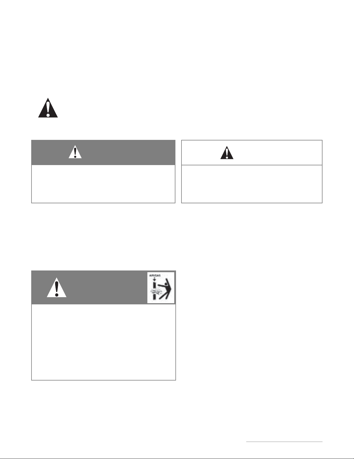
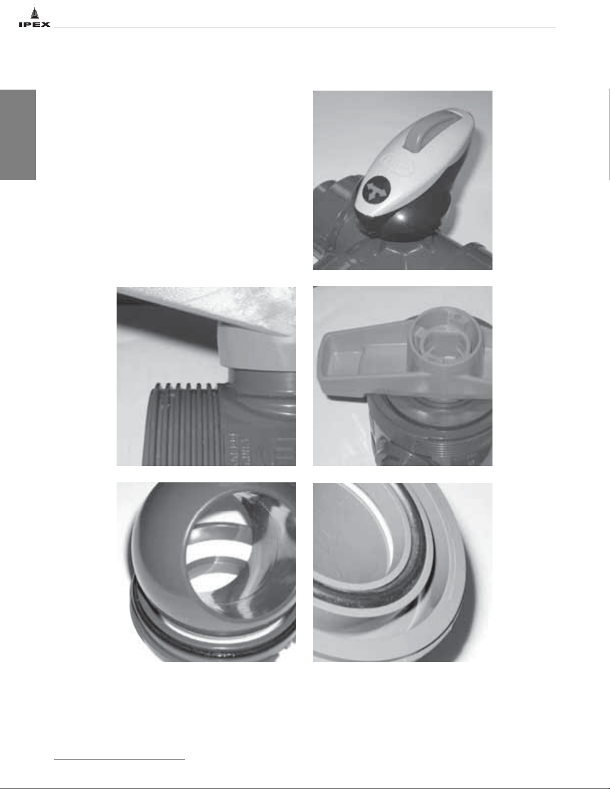
IPEX valves have extensive features and benefits unrivalled
by the competition. The compact and double blocking design
of our ball valves makes them easy to install, yet safe while
conducting line maintenance. Machined components and
anti-frictions rings result in reduced seal wear and minimal
breakaway torque on all our quarter turn valves. Ergonomic
handles with incorporated safety lockouts can be removed to
reveal integrated ISO pads for direct mount actuation. Many
of our valves feature deep square style threads for improved
strength and reliability as well as thick o-rings and deep
grooves for maximum sealing. For a complete list of features
and benefits, please consult the Thermoplastic Valve
Multimedia CD or the specific valve literature.
2
IPEX Thermoplastic Valves
CAUTION: Do not use or test the products in this manual with compressed air or other gases including air-over-water-boosters.
Page 10
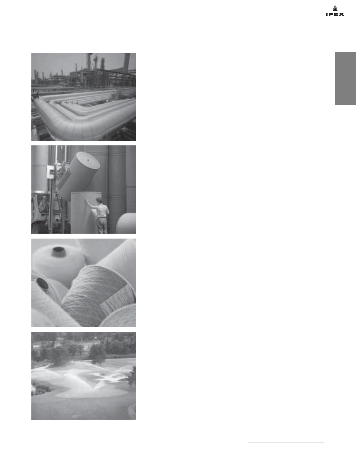
APPLICATIONS
Industrial and Process Piping
• Plant Water Supply and Distribution Lines
• Cooling Water Systems
• Chemical and Washwater Systems for Photographic Laboratories
• Acid Products Handling for Refineries, Metal Works and Plating Plants
• Bleach, Dye and Acid Lines in Textile Mills
• Deionized Water
• Tailing and Slurry Lines in Mines, Smelters and Fertilizer Plants
• Vacuum Piping
• Pure Chemicals for Semiconductor & Pharmaceutical Industries
• Piping in Fish Hatcheries, Aquariums, Zoological and Biological Buildings
• Well Casings and Dewatering Lines
• Drainage and Effluent Piping
• Swimming Pool Piping
• Rainwater Leaders for Buildings
Pulp and Paper
INFORMATION
GENERAL
• Pulp/Chemical Recovery Systems
• Bleach Plant Piping Systems
• Washwater Piping and Lagoon Systems
Food Processing
• Brine and Seawater Distribution in Fish Plants
• Brine Systems in Meat Packaging Plants
• Piping for the Dairy, Canning and Beverage Industries
Water and Sewage Treatment
• Alum and Ferric Chloride Handling
• Chlorine Injection Systems
• Piping in Lagoons and Settling Ponds
• Rainwater Lines
Irrigation
• Golf Courses
• Greenhouses
• Agriculture
• Residential Turf
• Commercial Turf
IPEX Thermoplastic Valves
CAUTION: Do not use or test the products in this manual with compressed air or other gases including air-over-water-boosters.
3
Page 11

MATERIAL DESCRIPTION
GENERAL
INFORMATION
PVC (Polyvinyl Chloride)
PVC is the most frequently specified of all thermoplastic
materials and has been used successfully for over 60 years.
PVC is characterized by distinctive physical properties, and is
resistant to corrosion and chemical attack by acids, alkalis,
salt solutions and many other chemicals. It is attacked,
however, by polar solvents such as ketones and aromatics. Of
the various types and grades of PVC used in plastic piping
systems, Type 1, Grade 1 PVC (Cell Classification 12454)
conforming to ASTM D1784 is the most common.
CPVC (Chlorinated Polyvinyl Chloride)
CPVC (Cell Classification 23447) conforming to
ASTM D1784 has physical properties at 73°F (23ºC) similar
to those of PVC and chemical resistance similar to or
generally better than that of PVC. With a design stress of
2,000psi and maximum service temperature of 210°F
(99ºC), CPVC has proved to be an excellent material for hot
corrosive liquids, hot and cold water distribution and similar
applications above the temperature range of PVC.
PP (Polypropylene)
Polypropylene is a lightweight polyolefin that is generally high
in chemical resistance. Although Type 1 Polypropylene
conforming to ASTM D2146 is slightly lower in physical
properties than PVC, it is chemically resistant to organic
solvents as well as acids and alkalies. Generally, polypropylene
should not be used in contact with strong oxidizing acids,
chlorinated hydrocarbons and aromatics. Polypropylene has a
design stress of 1,000psi at 73°F (23ºC).
ABS (Acrylonitrile-Butadiene-Styrene)
ABS identifies a broad family of engineering thermoplastics
with a range of performance characteristics. The copolymeric
system can be blended to yield the optimum balance of
properties suited to a selected end use. Acrylonitrile imparts
chemical resistance and rigidity. Butadiene endows the
product with impact strength and toughness, while Styrene
contributes to ease of processing.
EPDM (Ethylene propylene diene monomer)
EPDM is the abbreviation, issued by ASTM, for elastomers
derived from the propylene and ethylene copolymer. The
absence of unsaturation groups at the molecular level gives
EPDM excellent resistance to oxidation products but will
show a certain swelling when in contact with mineral and
petroleum oils, diester base lubricants and organic solvents.
Its operating temperature ranges from -65ºF to 284°F
(-54ºC to 140°C).
FPM (Vinylidene fluorine rubber)
FPM is the abbreviation, issued by ASTM, for fluorocarbon
elastomers derived from vinylidene fluorine copolymers.
Trade names include Viton A&B
Characterized by excellent resistance to heat and chemical
agents, FPM is virtually inert to oil and most solvents and
exhibits good chemical resistance to many aromatic and
aliphatic hydrocarbons. Its working temperature range is
considered to be from -13°F to 392°F (-25°C to 200°C)
although it has been known to seal at very low
temperatures such as -58°F (-50°C).
TM
or TecnoflonTM.
PVDF (Polyvinylidene Fluoride)
Polyvinylidene Fluoride is a strong, abrasion-resistant
thermoplastic with excellent heat stability and chemical
resistance typical of fluorocarbon polymers. It can be used in
temperatures up to 300°F (149ºC) with a wide variety of
acids, bases and organic solvents, and is ideally suited for
handling wet or dry chlorine, bromine and other halogens. No
other thermoplastic piping material can approach the
combination of strength, chemical resistance and operating
temperature that PVDF piping systems can offer.
PTFE (Polytetrafluorethylene)
PTFE or polytetrafluorethylene is a fluorinated polymer
characterized by a high molecular weight and a nearly
complete chemical resistance to reactives and solvents.
Thanks to its characteristics of self-lubrication, shock
resistance and extraordinary chemical inertness,
polytetrafluorethylene polymers, under trade names such as
TeflonTM, FluonTMand ArgoflonTM, have been successfully used
in the manufacture of sealing components. Among
thermoplastic resins, PTFE allows the highest working
temperatures. It can be used at constant temperatures of up
to 500°F (260°C).
4
IPEX Thermoplastic Valves
CAUTION: Do not use or test the products in this manual with compressed air or other gases including air-over-water-boosters.
Page 12
VALVE TYPES
By definition, a valve is any device that regulates the flow of gases, liquids, or loose materials through piping or through
apertures by opening, closing, or obstructing ports or passageways. Some main categories of valve types are as follows:
Ball Valves
Ball valves are generally used for on/off service, but can range from simple
molded-in-place construction to high-end industrial designs with many
features and benefits. Multi-port ball valves allow for mixing, diverting, and
bypassing flow. Their name is derived from the modified ball in the center of
the valve which allows flow to enter and exit through two or more ports. This
ball is tightly held between multiple seats, and is cycled via a stem-handle
connection. They are typically categorized as "quarter turn" or 90° valves, and
can be easily automated. Many ball valves feature full port flow, blocking true
union ends, and compact ergonomic designs allowing for simple installation
and maintenance.
Butterfly Valves
These highly versatile valves can be used for simple on/off service but also
for processes requiring precise throttling. They get their name from the stemdisc assembly that controls the flow. Cycling the valve just 90° allows full
travel from the closed position (disc perpendicular to the pipeline) to the
open position (disc parallel to the pipeline) or vice versa. A continuous flow
profile between fully closed and fully open makes these valves ideal for use
in modulating service. While typically connected to the system between two
flanges, end-of-line installation is possible while maintaining pressure
upstream. An extensive size range and direct mount actuation make them
suitable for a wide range of applications.
INFORMATION
GENERAL
Diaphragm Valves
These valves are the perfect solution when precise flow throttling is required.
Their design employs a flexible "diaphragm" component which is compressed
against the body of the valve to provide a bubble tight seal. The weir style
design is extremely good for abrasive slurries as there is no "dead space" for
particles to become trapped. They are widely used in high purity applications
because their design prevents friction and subsequent particle creation when
cycling. Only the body and diaphragm are in contact with the process media.
Due to the modular nature of the design, many body styles, diaphragm and
seal materials, and actuation options are available.
Check and Vent Valves
Check valves are unidirectional and should be used whenever there is a need
to prevent back-flow of process media. This may be when two incompatible
fluids cannot be allowed to mix, or when reverse flow would cause
undesirable drainage of a system line or tank. Many styles exist including:
simple ball checks, heavy duty swing checks, and highly efficient piston
checks. These valves are typically gravity operated and require very little back
pressure seal. Air release or vent valves safely allow any entrapped air or gas
to escape, avoiding potential damage to the piping system.
Specialty Valves
IPEX offers a few specialized valves for a variety of process requirements.
Sediment strainers trap suspended particles flowing in the process line,
ensuring that downstream components are protected. Solenoid valves are
ideal for high-cycle applications where remote operation and precise control
are important. Lab valves are an economical solution for small scale on/off
requirements.
IPEX Thermoplastic Valves
CAUTION: Do not use or test the products in this manual with compressed air or other gases including air-over-water-boosters.
5
Page 13

The following table should be used as a guide only as some valves only offer certain combinations of sizes, materials,
connections, and pressure capabilities.
Always consult the specific valve style section for complete information regarding
availability and technical performance.
IPEX Thermoplastic Valves
GENERAL
INFORMATION
Valve
Series
VKD Ball 1/2 to 4 PVC, CPVC, PP, ABS TU (S, T), Sm 232
VX Ball 1/2 to 6 PVC, CPVC TU (S, T), F
VE Ball 1/2 to 2 PVC TU (S, T) 232
MP Compact Ball 1/2 to 2 PVC S, T 150
TK 3-Way Ball 1/2 to 2 PVC TU (S, T) 232
VT/VL 3-Way Ball 1/2 to 2 PVC, PP TU (S, T), F, Sm 150
FK Butterfly 1-1/2 to 12 PP, PVC, CPVC, PVDF F (W, L)
FE Butterfly 1-1/2 to 12 PVC F (W)
VM Diaphragm
DV Diaphragm 1/2 to 6 PVC F 150
Valve Type
Sizes
(in)
1/2 to 4
20 to 110 (mm)
Materials End Connections
PVC, CPVC, PP, PVDF TU (S, T), F, Sp, Sm 150
Pressure Rating
(PSI)
232 (1/2" to 2")
150 (2-1/2" to 4")
150 (1-1/2" to 10")
120 (12")
232 (1/2" to 2")
150 (2-1/2" to 8")
75 (10" to 12")
CM Compact Diaphragm
DM Diaphragm 1/2 to 2 PVC TU (S, T), F, Sp 120
VB Ball Check 1/2 to 4 PVC, CPVC TU (S, T), F 150
VR Piston Check 1/2 to 4 PVC TU (S, T), S, T, F
SC Swing Check 3 to 8 PVC F
VA Air Release 3/4, 1-1/4, 2 PVC SU (S, T) 232
RV Strainer 1/2 to 4 PVC, CPVC TU (S, T), S, T, F
SF Solenoid 1/4, 1/2 PVC TU (T)
LV Lab 1/4 PVC T 150
TU = True Union, SU = Single Union, S = Socket (IPS), T = Threaded (NPT), F = Flanged (ANSI 150),
W = Wafer, L = Lugged, Si = Spigot (IPS), Sm = Socket (Metric), Sp = Spigot (Metric)
1/2
16 to 20 (mm)
PVC, CPVC, PP, PVDF TU (S, T), Sp, Sm 90
232 (1/2" to 1")
150 (1-1/4" to 2")
90 (3" to 4")
100 (3")
70 (4" to 8")
232 (1/2" to 1")
150 (1-1/4" to 2")
60 (3" to 4")
30 (1/4)
60 (1/2)
6
IPEX Thermoplastic Valves
CAUTION: Do not use or test the products in this manual with compressed air or other gases including air-over-water-boosters.
Page 14
VALVE SELECTION
As is the case with other thermoplastic components in a
processing system, valves must be selected based on the
characteristics of the fluid medium, the system's operating
parameters, and its intended function for a particular
application. Certain valve types are more suitable than others
for on/off service, throttling or modulating, automation, back
flow prevention, etc.
Fluid Properties
Like other system components, the material that is used in
valve construction should be chosen depending on the
chemistry of the fluid. Different plastics have varying abilities to
handle certain chemical types. In a given piping system, the
material selected for a valve is typically the same as what is
specified for the pipe and fittings. However, since valves
contain other components such as seats and seals, particular
attention should be paid to their material selection. Please
consult IPEX's Chemical Resistance Guide for specific materialfluid compatibilities. Abrasiveness, viscosity, and other fluid
properties are sometimes important to consider as well.
Temperature and Pressure
As with pipe and fittings, the strength of a valve is limited by
the operating temperature and pressure of the system.
However, the type of failure that can be expected in valves is
different than that of other piping components as valves
typically contain seats, seals, and moving components. These
critical points can be potentially displaced if the seat or seal
housing softens or distorts due to excessive prolonged heat.
This can result in a loss of pressure capacity if these contact
points lose competence. During the design, manufacture, and
assembly of IPEX valves, careful attention is given to these
vital connections in order to compensate for reduced
performance under extreme conditions.
Valves are typically pressure rated by style; however size,
material type, and temperature play significant roles in
determining the pressure capabilities of a specific valve.
Since they are often constructed of more than one material
type, it is important to review the pressure-temperature
relationship. General pressure ratings are given assuming an
ambient operating temperature of 73°F (23ºC), above which
the maximum pressure capability decreases. To account for
this, detailed pressure-temperature graphs are included in
this manual for each valve type.
Flow rate
An important consideration in valve selection is the intended
flow rate of the system. The flow rate of a particular valve is
expressed as a CV coefficient. This value represents the
number of gallons per minute (GPM) that will flow through a
fully open valve with a 1psi pressure drop at 68°F (20ºC).
These values are determined from an industry standard
testing procedure which uses water as the flowing media
(specific gravity of 1.0). Tables showing acceptable flow rates
for different size valves are included in this manual for each
valve type.
Vacuum Service
Many of our valves have been tested to determine their
ability to withstand service under vacuum conditions. Our
ball, butterfly, and diaphragm valves have been tested to hold
a vacuum in excess of 29 inches of mercury. Please contact
the IPEX technical services department for specific vacuum
service applications.
Other Considerations
Occasionally it may be important to select a particular valve
based on spatial constraints or weight limitations. Some
compact light weight valves are better suited to applications
where space is limited and/or pipe support is not possible.
Requirements such as automation or remote operation may
also demand the selection of a particular valve. For details
regarding actuated ball and butterfly valves, please refer to
the IPEX Industrial technical manual entitled "Quarter Turn
Automation".
INFORMATION
GENERAL
IPEX Thermoplastic Valves
CAUTION: Do not use or test the products in this manual with compressed air or other gases including air-over-water-boosters.
7
Page 15

FURTHER INFORMATION
GENERAL
INFORMATION
System Design
The necessity and selection of valves for use in a piping
system is largely a function of the overall process
requirements. For detailed information regarding the design
process and associated considerations, please refer to the
IPEX Industrial technical manual entitled "Vinyl Process
Piping Systems".
Installation Considerations
For detailed information regarding piping installation and
associated considerations, please refer to the IPEX Industrial
technical manual entitled "Vinyl Process Piping Systems". For
particular valve installation instructions, please refer to the
specific valve type section in this manual.
Testing and Operating
The purpose of system testing is to assess the quality of all
joints and fittings to ensure that they will withstand the
design working pressure, plus a safety margin, without loss of
pressure or fluid. Typically, the system will be tested and
assessed in sub-sections as this allows for improved isolation
and remediation of potential problems. With this in mind, the
testing of a specific installed valve is achieved while carrying
out a test of the overall system.
An onsite pressure test procedure is outlined in the IPEX
Industrial technical manual entitled "Vinyl Process Piping
Systems" under the section entitled, "Testing". The use of this
procedure should be sufficient to assess the quality of a valve
installation. In any test or operating condition, it is important
to never exceed the pressure rating of the lowest rated
appurtenance in the system.
Important points
• Never test thermoplastic piping systems with
compressed air or other gases including air-over-water
boosters.
• When testing, do not exceed the rated maximum
operating pressure of the valve.
• Avoid the rapid closure of valves to eliminate the
possibility of water hammer which may cause damage to
the pipeline or the valve.
There are certain applications where proper standard
procedure for valve selection may still result in operating
problems. For example, when conveying volatile liquids such
as hydrogen peroxide (H
(NaClO) through ball valves, these liquids may vaporize
causing a potentially dangerous pressure increase in the dead
space between the ball and the valve body. If left unchecked,
this pressure buildup can result in catastrophic failure of the
valve. IPEX offers specially modified ball valves for these
types of critical applications.
) and sodium hypochlorite
2O2
Maintenance
IPEX valves are designed and manufactured to high quality
standards with long service life expectancy. However, if
maintenance is required, please refer to the specific valve
type section in this manual for instructions.
8
IPEX Thermoplastic Valves
CAUTION: Do not use or test the products in this manual with compressed air or other gases including air-over-water-boosters.
Page 16
SECTION TWO: BALL VALVES
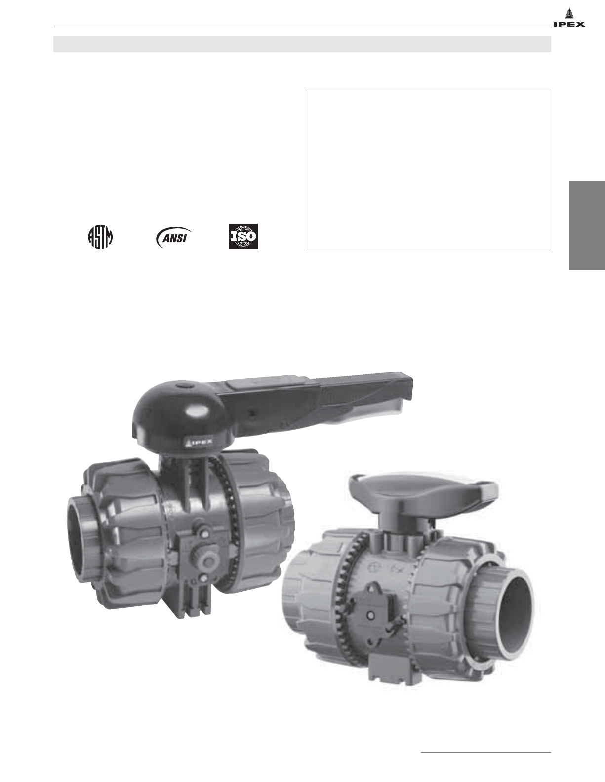
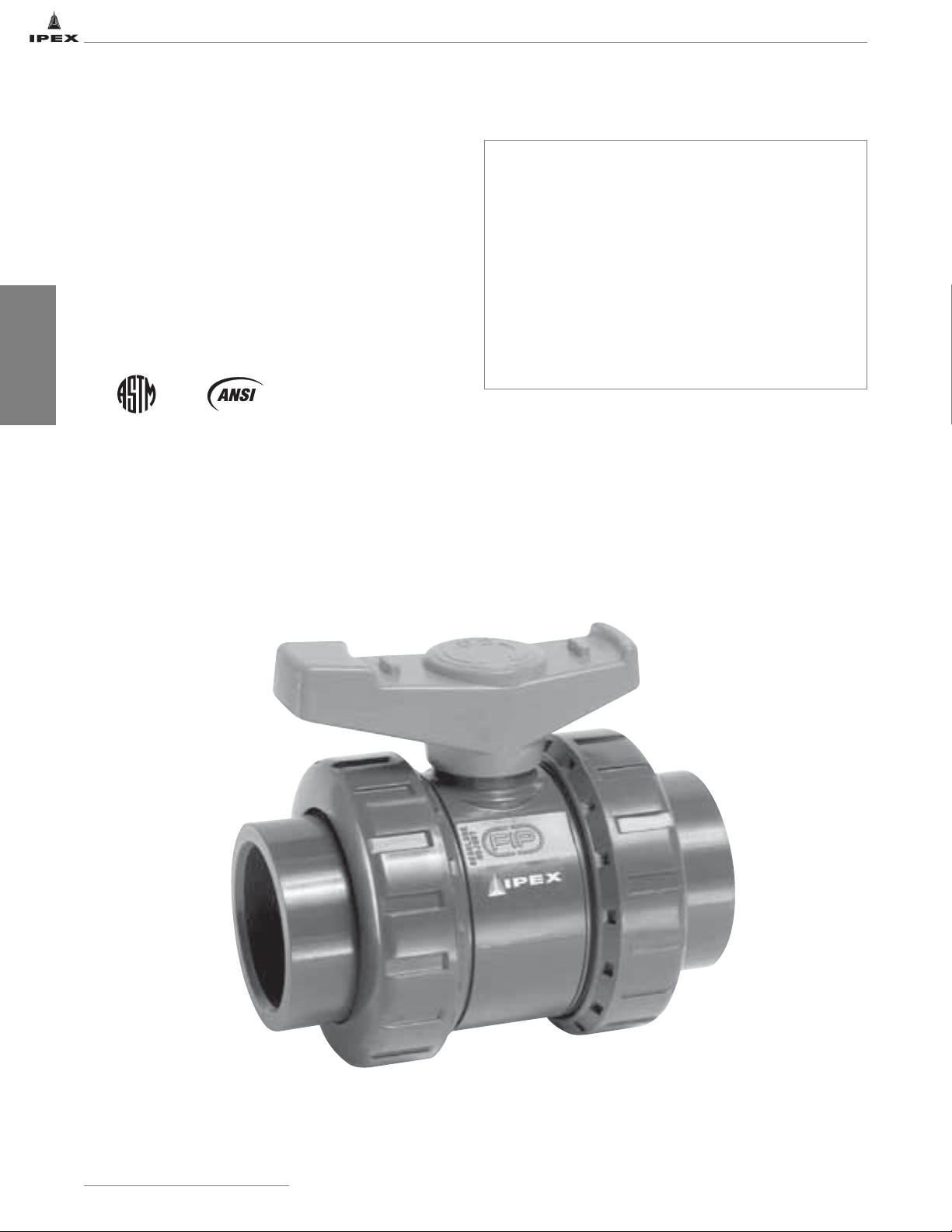
VKD SERIES BALL VALVES
IPEX VKD Series Ball Valves offer a variety of advanced
features such as the patented seat stop carrier, a high quality
stem and ball support system, and a multifunctional locking
handle. Deep grooves, thick o-rings, and cushioned Teflon
seats contribute to strong seals at pressures up to 232psi
while an integral ISO mounting flange and support bracketing
combine for simple actuation and anchoring. VKD Series Ball
Valves are part of our complete Xirtec®140, Corzan®, SFPP and
Duraplus®systems of pipe, valves, and fittings, engineered and
manufactured to our strict quality, performance, and
dimensional standards.
Valve Availability
Body Material: PVC, CPVC, PP, ABS
®
Size Range: 1/2" through 4"
Pressure: 232psi
150psi (PP)
Seats: Teflon
Seals: EPDM or Viton
End Connections: Socket (IPS)
®
Threaded (FNPT)
Socket (Metric)
(PTFE)
®
(FPM)
BALL VALVES
ASTM D1784
ASTM D2464
ASTM D2466
ASTM D2467
ASTM D4101
ASTM F437
ASTM F439
ASTM F1498
ANSI B1.20.1
ISO 11922-1
IPEX Thermoplastic Valves
CAUTION: Do not use or test the products in this manual with compressed air or other gases including air-over-water-boosters.
9
Page 17
BALL VALVES
VKD SERIES BALL VALVES
Sample Specification
1.0 Ball Valves - VKD
1.1 Material
• The valve body, stem, ball and unions shall be made of
PVC compound which shall meet or exceed the
requirements of cell classification 12454 according to
ASTM D1784.
or The valve body, stem, ball and unions shall be made of
or The valve body, stem, ball and unions shall be made of
or The valve body, stem, ball and unions shall be made of
1.2 Seats
• The ball seats shall be made of Teflon
1.3 Seals
• The o-ring seals shall be made of EPDM.
or The o-ring seals shall be made of Viton
1.4 All wetted parts of the valves shall comply with
2.0 Connections
2.1 Socket style
• The IPS socket PVC end connectors shall conform to
or The IPS socket CPVC end connectors shall conform to
or The Metric socket PP end connectors shall conform to
2.2 Threaded style
• The female NPT threaded PVC end connectors shall
or The female NPT threaded CPVC end connectors shall
or The female NPT threaded PP end connectors shall
®
Corzan
CPVC compound which shall meet or exceed
the requirements of cell classification 23447 according
to ASTM D1784.
stabilized PP homopolymer compound, also containing
a RAL 7032 pigment, which shall meet or exceed the
requirements of Type I Polypropylene according to
ASTM D4101.
Duraplus
®
ABS compound which shall meet or exceed
the requirements of cell classification 43234 according
to ASTM D3965.
®
(PTFE).
®
(FPM).
standards that are equivalent to NSF Standard 61 for
potable water.
the dimensional standards ASTM D2466 and ASTM
D2467.
the dimensional standard ASTM F439.
the dimensional standard ISO 11922-1.
conform to the dimensional standards ASTM D2464,
ASTM F1498, and ANSI B1.20.1.
conform to the dimensional standards ASTM F437,
ASTM F1498, and ANSI B1.20.1.
conform to the dimensional standards ASTM F1498,
and ANSI B1.20.1.
3.0 Design Features
• The valve shall be double blocking with union ends.
• All valves shall be full port.
• All valves shall allow for bi-directional flow.
• The valve body shall be single end entry with a
threaded carrier (ball seat support).
• The threaded carrier shall be adjustable with the valve
installed.
• The valve body shall have an expansion and contraction
compensating groove on the molded end.
• The valve body, union nuts, and carrier shall have deep
square style threads for increased strength.
• The ball and stem shall be machined smooth to
minimize wear on valve seats and seals.
• All valve seats shall have o-ring backing cushions to
compensate for wear and prevent seizure of the ball.
• The stem design shall feature double o-ring seals as
well as a safety shear point above the o-rings.
• All valves shall have integrally molded mounting
features for actuation.
• All valves shall have integrally molded support
bracketing for anchoring.
• The valve shall include the Dual Block
®
union nut
locking mechanism.
3.1 Pressure Tested
• All valves shall have been pressure tested in both the
open and closed positions by the manufacturer.
3.2 Pressure Rating
• All PVC, CPVC and ABS valves shall be rated at
232psi at 73°F (23ºC).
• All PP valves shall be rated at 150psi at 73°F (23ºC).
3.3 Markings
• All valves shall be marked to indicate size, material
designation, and manufacturers name or trade mark.
3.4 Color Coding
• All PVC valves shall be color-coded dark gray.
or All CPVC valves shall be color-coded light gray.
or All PP valves shall be color-coded beige gray.
or All ABS valves shall be color-coded light gray.
4.0 All valves shall be Xirtec
Duraplus
®
by IPEX or approved equal.
®
140, Corzan®, SFPP or
10
IPEX Thermoplastic Valves
CAUTION: Do not use or test the products in this manual with compressed air or other gases including air-over-water-boosters.
Page 18
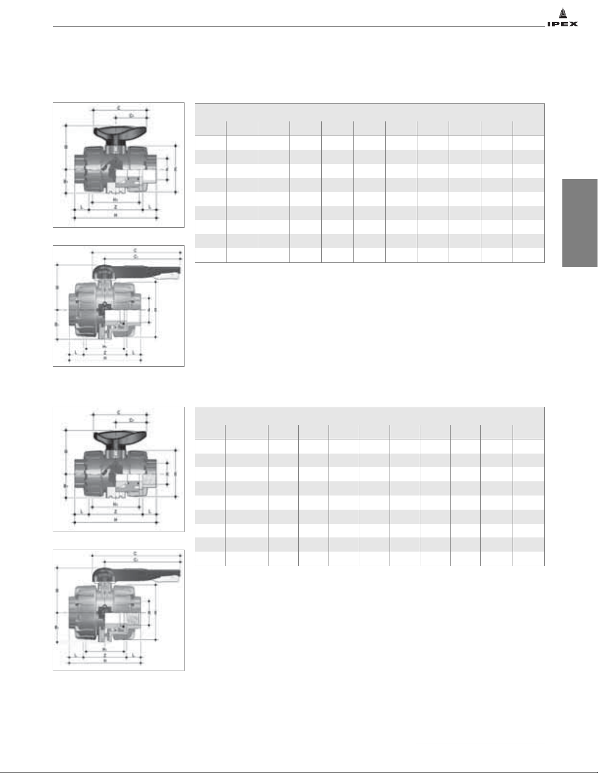
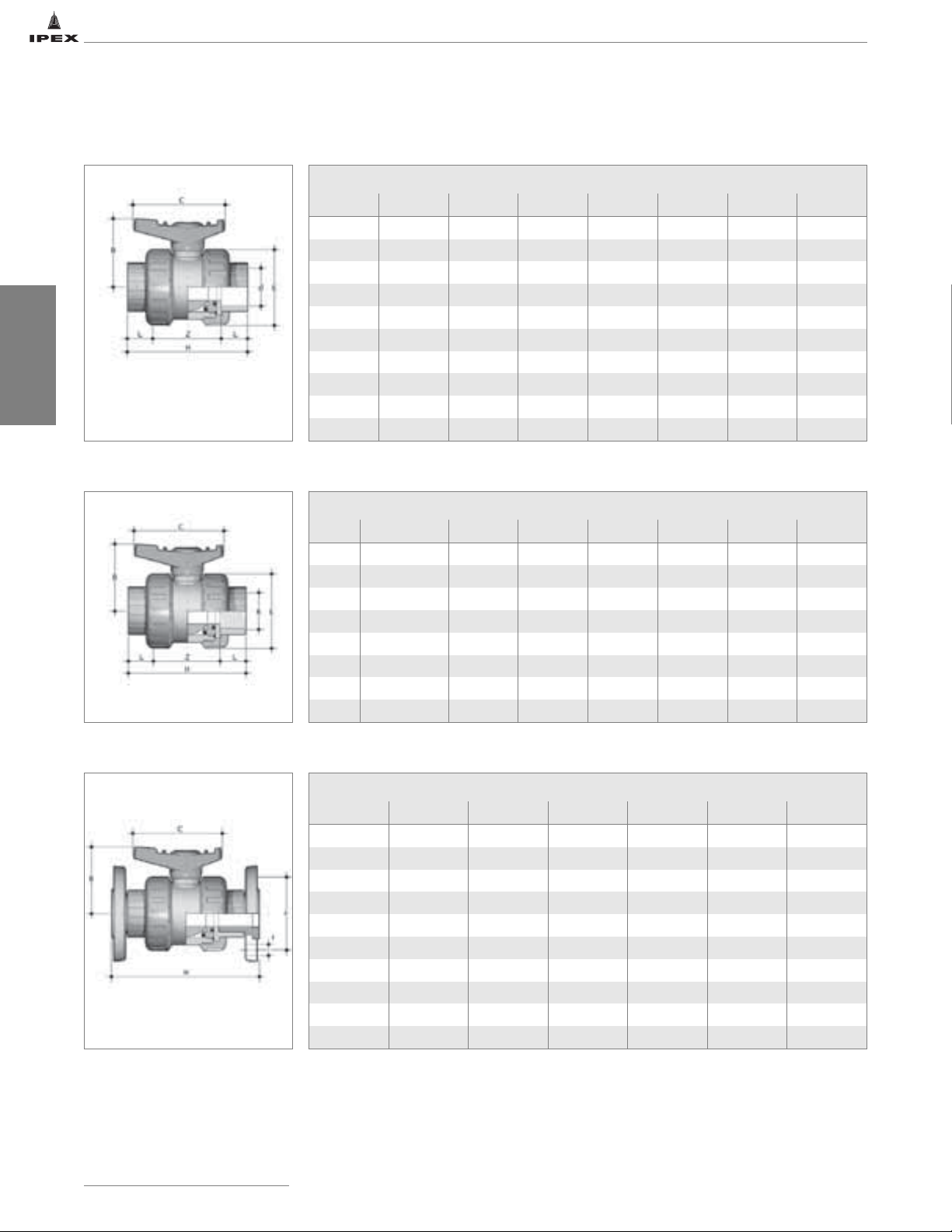
Dimensions
Sizes 1/2" to 2"
VKD SERIES BALL VALVES
IPS Socket Connections - Dimension (inches)
Size d H L Z H1 E B1 B C1 C
1/2 0.84 4.61 0.89 2.83 2.56 2.13 1.14 2.13 1.57 2.64
3/4 1.05 5.08 1.00 3.07 2.76 2.56 1.36 2.56 1.93 3.35
1 1.32 5.59 1.13 3.33 3.07 2.87 1.54 2.74 1.93 3.35
1-1/4 1.66 6.38 1.26 3.86 3.46 3.39 1.81 3.25 2.52 4.25
1-1/2 1.90 6.77 1.38 4.02 3.66 3.86 2.05 3.50 2.52 4.25
2 2.38 7.83 1.50 4.83 4.37 4.80 2.44 4.25 2.99 5.28
2-1/2 2.88 9.25 1.75 5.75 5.24 6.46 3.43 6.46 6.89 8.86
3 3.50 10.63 1.89 6.85 5.87 7.99 4.13 6.97 10.71 12.87
4 4.50 12.13 2.26 7.60 6.57 9.37 5.08 7.68 12.99 15.16
BALL VALVES
Sizes 2-1/2" to 4"
Sizes 1/2" to 2"
Female NPT Threaded Connections - Dimension (inches)
Size R H L Z H1 E B1 B C1 C
1/2 1/2-NPT 4.37 0.70 2.97 2.56 2.13 1.14 2.13 1.57 2.64
3/4 3/4-NPT 4.61 0.71 3.19 2.76 2.56 1.36 2.56 1.93 3.35
1 1-NPT 5.31 0.89 3.54 3.07 2.87 1.54 2.74 1.93 3.35
1-1/4 1-1/4-NPT 6.02 0.99 4.05 3.46 3.39 1.81 3.25 2.52 4.25
1-1/2 1-1/2-NPT 6.14 0.97 4.20 3.66 3.86 2.05 3.50 2.52 4.25
2 2-NPT 7.32 1.17 4.99 4.37 4.80 2.44 4.25 2.99 5.28
2-1/2 2-1/2-NPT 9.25 1.31 6.64 5.24 6.46 3.43 6.46 6.89 8.86
3 3-NPT 10.63 1.40 7.83 5.87 7.99 4.13 6.97 10.71 12.87
4 4-NPT 12.13 1.48 9.17 6.57 9.37 5.08 7.68 12.99 15.16
Sizes 2-1/2" to 4"
IPEX Thermoplastic Valves
CAUTION: Do not use or test the products in this manual with compressed air or other gases including air-over-water-boosters.
11
Page 19
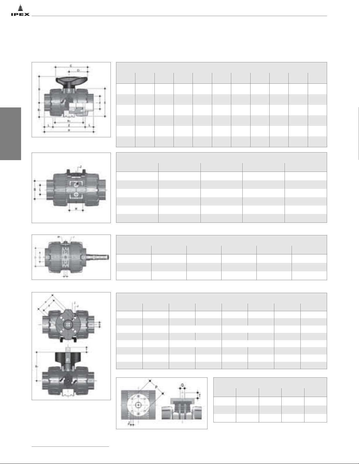
Dimensions
VKD SERIES BALL VALVES
Metric Socket Connections - Dimension (inches)
Size d H L Z H1 E B1 B C1 C
20mm 0.79 4.02 0.57 2.87 2.56 2.13 1.14 2.13 1.57 2.64
25mm 0.98 4.49 0.63 3.23 2.76 2.56 1.36 2.56 1.93 3.35
32mm 1.26 4.96 0.71 3.54 3.07 2.87 1.54 2.74 1.93 3.35
40mm 1.57 5.55 0.81 3.94 3.35 3.39 1.81 3.25 2.52 4.25
50mm 1.97 6.46 0.93 4.61 3.66 3.86 2.05 3.50 2.52 4.25
BALL VALVES
Sizes 20mm to 63mm
Sizes 1/2" to 2"
Sizes 2-1/2" to 4"
63mm 2.48 7.83 1.08 5.67 4.37 4.80 2.44 4.25 2.99 5.28
Support Bracket - Dimension (inches)
Size J B L H
1/2 M4 1.24 0.79 1.06
3/4 M4 1.57 0.79 1.18
1 M4 1.57 0.79 1.18
1-1/4 M6 1.97 1.18 1.38
1-1/2 M6 1.97 1.18 1.38
2" M6 2.36 1.18 1.57
Support Bracket - Dimension (inches)
Size J f I I1 I2
2-1/2 M6 0.25 0.69 3.54 2.04
3 M8 0.33 0.83 4.43 2.48
4 M8 0.33 0.83 5.39 2.64
Actuation Pad - Dimension (inches)
Size B2 p P j J T Q
1/2 2.28 F03 F04 0.22 0.22 0.47 0.43
3/4 2.89 F03 F05 0.22 0.26 0.47 0.43
*3/4 2.89 F04 0.22 0.47 0.43
1 2.91 F03 F05 0.22 0.26 0.47 0.43
*1 2.91 F04 0.22 0.43 0.43
1-1/4 3.82 F05 F07 0.26 0.33 0.63 0.55
1-1/2 4.09 F05 F07 0.26 0.33 0.63 0.55
2 4.49 F05 F07 0.26 0.33 0.63 0.55
12
Actuation Pad - Dimension (inches)
Size P J T Q
Sizes 1/2" to 2"
Sizes 2-1/2" to 4"
IPEX Thermoplastic Valves
CAUTION: Do not use or test the products in this manual with compressed air or other gases including air-over-water-boosters.
2-1/2 F07 0.35 0.63 0.55
3 F07 0.35 0.63 0.55
4 F07 0.35 0.75 0.67
Page 20
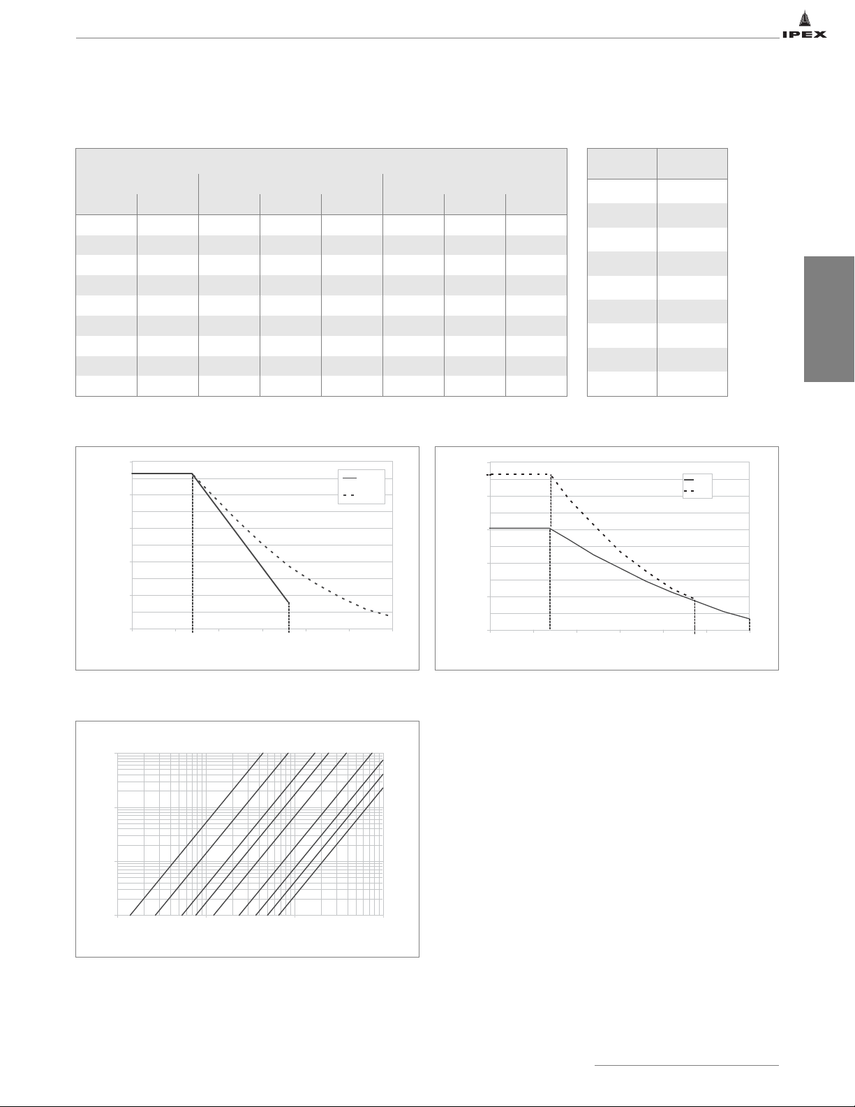
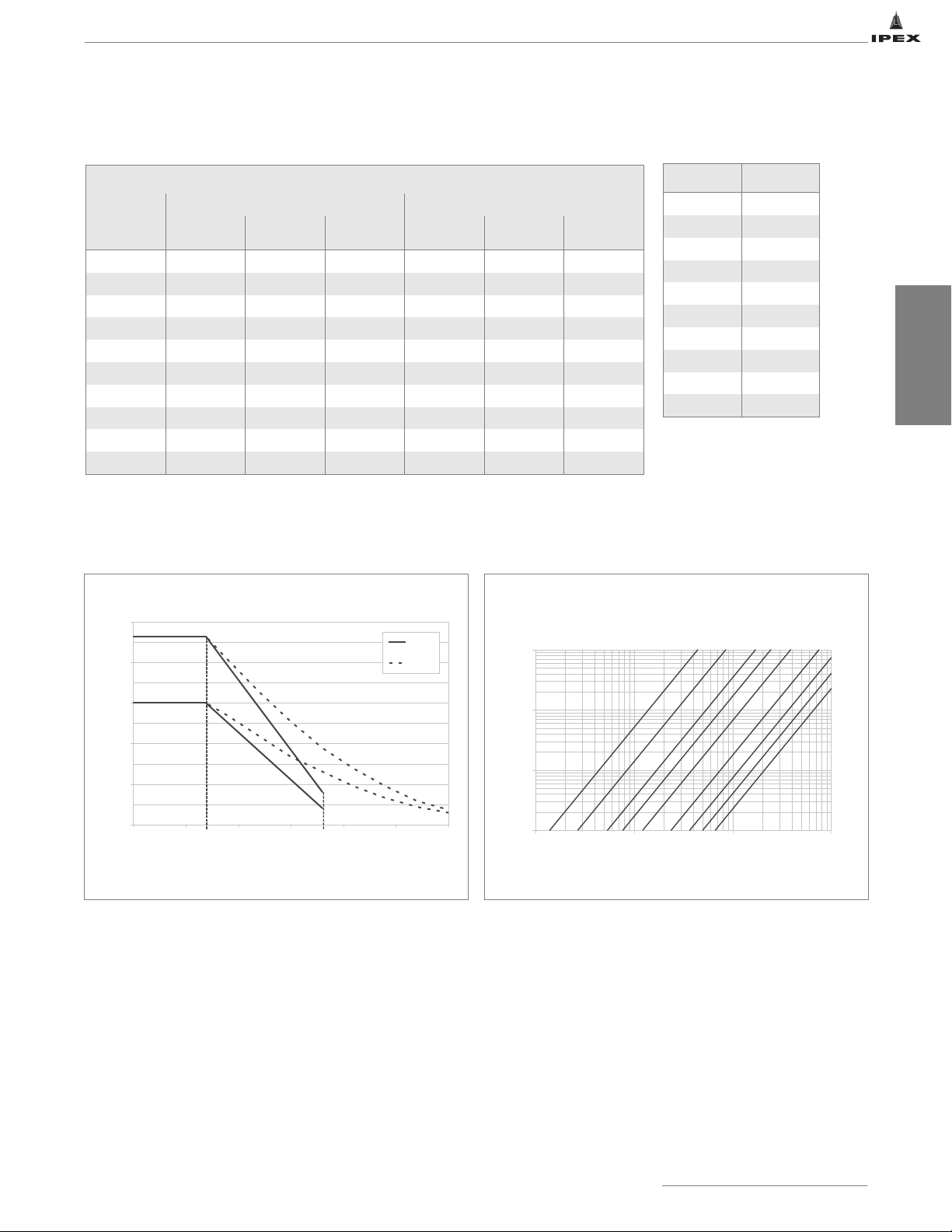
VKD SERIES BALL VALVES
0
50
100
150
200
250
32 62 92 122 152 182 212
Working Temperature (˚F)
Working Pressure (psi)
PVC
CPVC
73 140
232
232
176
1/2"
3/4"1"1-1/4"
1-1/2"2"2-1/2"
3"
4"
Flowrate (GPM)
Pressure loss (psi)
Weights
Approximate Weight (lbs)
Size (inches) IPS / Metric Socket FNPT Threaded
IPS Metric PVC CPVC PP PVC CPVC PP
1/2 20mm 0.47 0.51 0.32 0.46 0.50 0.31
3/4 25mm 0.76 0.82 0.48 0.74 0.79 0.50
1 32mm 0.99 1.06 0.66 0.99 1.06 0.67
1-1/4 40mm 1.58 1.70 1.06 1.49 1.61 1.01
1-1/2 50mm 2.15 2.31 1.50 2.11 2.26 1.43
2 63mm 3.77 4.06 2.57 3.68 3.95 2.50
2-1/2 - 9.68 10.50 - 9.69 10.50 -
3 - 15.90 17.30 - 16.00 17.40 -
4 - 24.40 26.90 - 24.50 27.00 -
Pressure – Temperature Ratings
250
200
150
Flow Coefficients
Size
1/2 14.0
3/4 27.0
1 53.9
1-1/4 77.0
1-1/2 123
2 238
2-1/2 368
3 497
4 665
C
V
BALL VALVES
PP
ABS
Pressure Loss Chart
10
0.1
0.01
1
1 10 100 1000
100
Working Pressure (psi)
50
0
32 62 92 122 152 182 212
73 140
Working Temperature (˚F)
CAUTION: Do not use or test the products in this manual with compressed air or other gases including air-over-water-boosters.
IPEX Thermoplastic Valves
13
Page 21
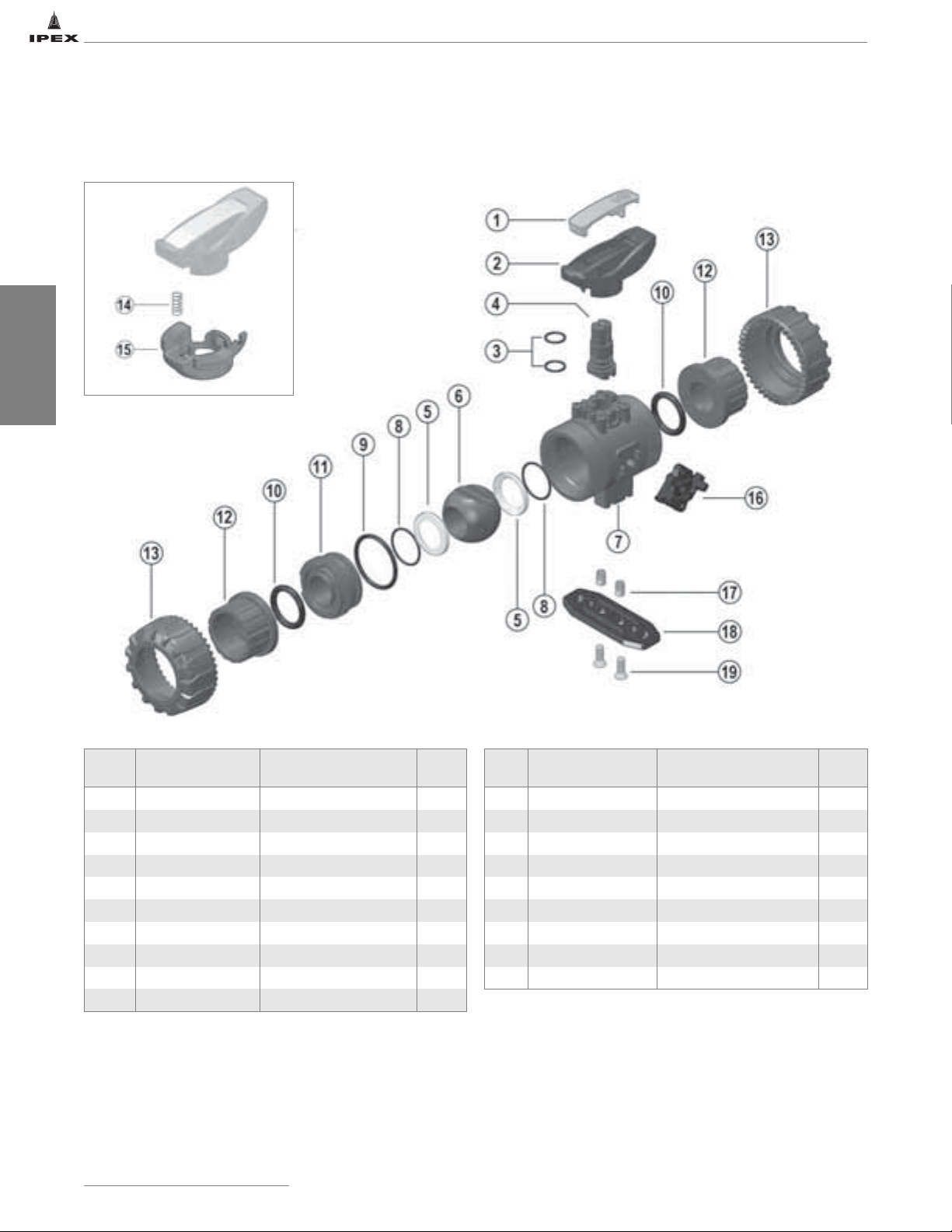
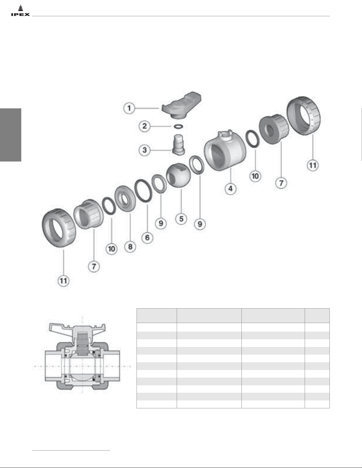
BALL VALVES
VKD SERIES BALL VALVES
Components
Sizes 1/2" to 2"
# Component Material Qty
1 insert PVC / CPVC / PP / ABS 1
2 handle PVC / CPVC / PP / ABS 1
3 stem o-ring EPDM / Viton
®
4 stem PVC / CPVC / PP / ABS 1
5 ball seat PTFE 2
6 ball PVC / CPVC / PP / ABS 1
7 body PVC / CPVC / PP / ABS 1
8 ball seat o-ring EPDM / Viton
9 body o-ring EPDM / Viton
10 socket o-ring EPDM / Viton
14
IPEX Thermoplastic Valves
CAUTION: Do not use or test the products in this manual with compressed air or other gases including air-over-water-boosters.
®
®
®
# Component Material Qty
11 carrier PVC / CPVC / PP / ABS 1
12 end connector PVC / CPVC / PP / ABS 2
2
13 union nut PVC / CPVC / PP / ABS 2
14* spring SS 1
15* handle lock GRPP 1
16 DUAL BLOCK
®
POM 1
17* bracket bushing SS / brass 2
2
1
2
18* mounting plate GRPP 1
19* screw SS 2
*Accessories
Page 22
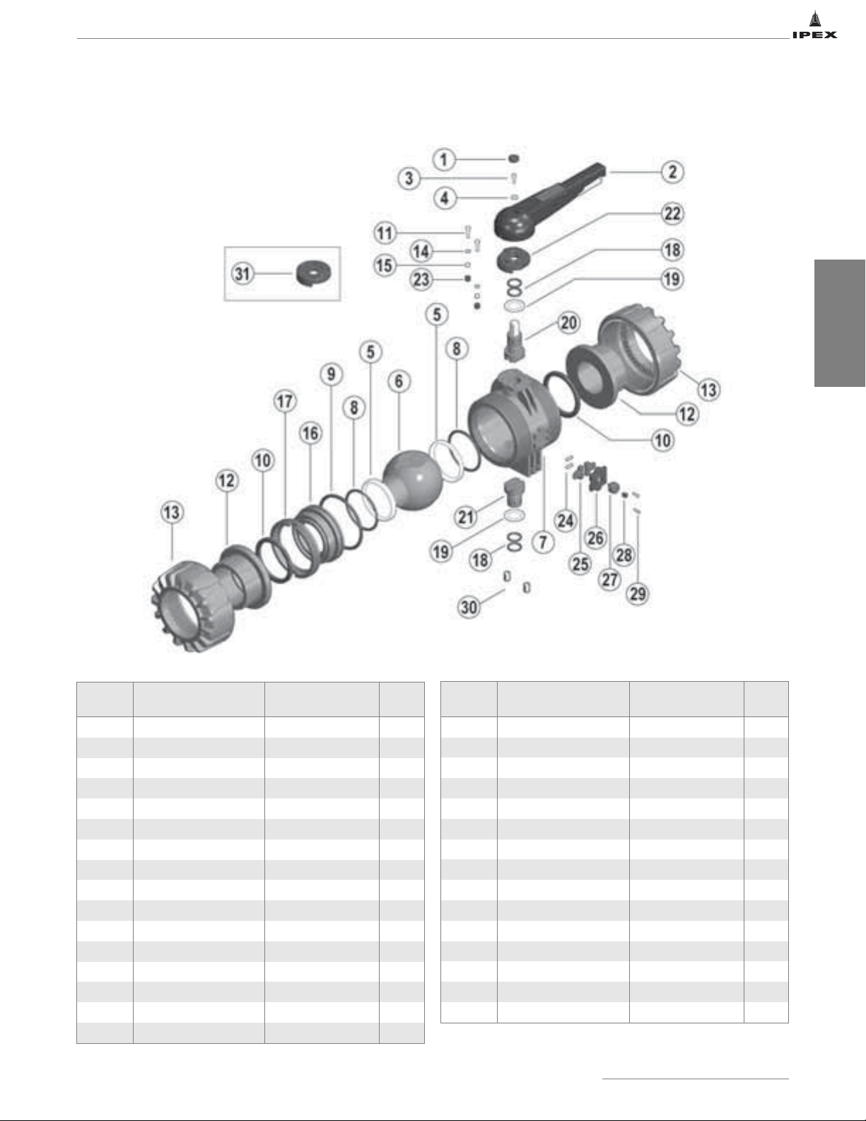
Components (cont’d)
VKD SERIES BALL VALVES
Sizes 2-1/2" to 4"
BALL VALVES
# Component Material Qty
1 protective cap PE
2 handle PVC 1
3 bolt SS
4 washer SS 1
5 ball seat PTFE
6 ball PVC / CPVC 1
7 body PVC / CPVC 1
8 ball seat o-ring EPDM / Viton
9 body o-ring EPDM / Viton
10 socket seal EPDM / Viton
®
®
®
11 bolt SS 2
12 end connector PVC / CPVC 2
13 union nut PVC / CPVC 2
14 washer SS 2
15 nut SS 2
1
1
2
2
1
2
# Component Material Qty
17 stop ring PVC / CPVC
18 stem o-ring EPDM / Viton
19 bushing PTFE
20 upper stem PVC / CPVC & SS 1
21 lower stem PVC / CPVC 1
22 pad GRPP 1
23 protective cap PE
24 spring SS 2
25 nut block GRPP 2
26 cover PP 1
27 nut block button GRPP 1
28 protective cap PE 1
29 screw nylon 2
30 bracket bushing brass 2
31 actuation pad GRPP 1
16 carrier PVC / CPVC 1
IPEX Thermoplastic Valves
CAUTION: Do not use or test the products in this manual with compressed air or other gases including air-over-water-boosters.
1
®
4
2
2
15
Page 23
VKD SERIES BALL VALVES
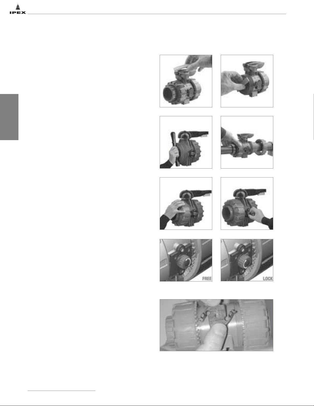
Installation Procedures
1. Remove the union nuts (part #13 on previous page) and
slide them onto the pipe.
2. Please refer to the appropriate connection style sub-section:
a. For socket style, solvent cement or fuse the end
connectors (12) onto the pipe ends. For correct
solvent cementing procedure, please refer to the
section entitled,
Cementing”
Series,
“Volume I: Vinyl Process Piping Systems”
Be sure to allow sufficient cure time before
continuing with the valve installation.
“Joining Methods - Solvent
in the IPEX Industrial Technical Manual
.
BALL VALVES
b. For threaded style, thread the end connectors (12)
onto the pipe ends. For correct joining procedure,
please refer to the section entitled,
Methods - Threading”
Technical Manual Series,
Piping Systems”
3. Open and close the valve to ensure that the carrier (11
or 16) is at the desired adjustment. If adjustment is
required, ensure that the valve is in the closed position
then remove the insert tool (1) from the handle (2). For
sizes 2-1/2" to 4", use the tool that accompanies the
valve. Line up the moldings on the tool with the slots in
the carrier. Tighten or loosen to the desired position then
replace the tool on the handle.
4. Ensure that the valve is in the closed position, and that
the socket o-rings (10) are properly fitted in their
grooves. If anchoring is required, insert the bracket
bushings (17) into the bottom of the valve (sizes 1/2" to
2" only). Carefully place the valve in the system between
the two end connections and fix if necessary.
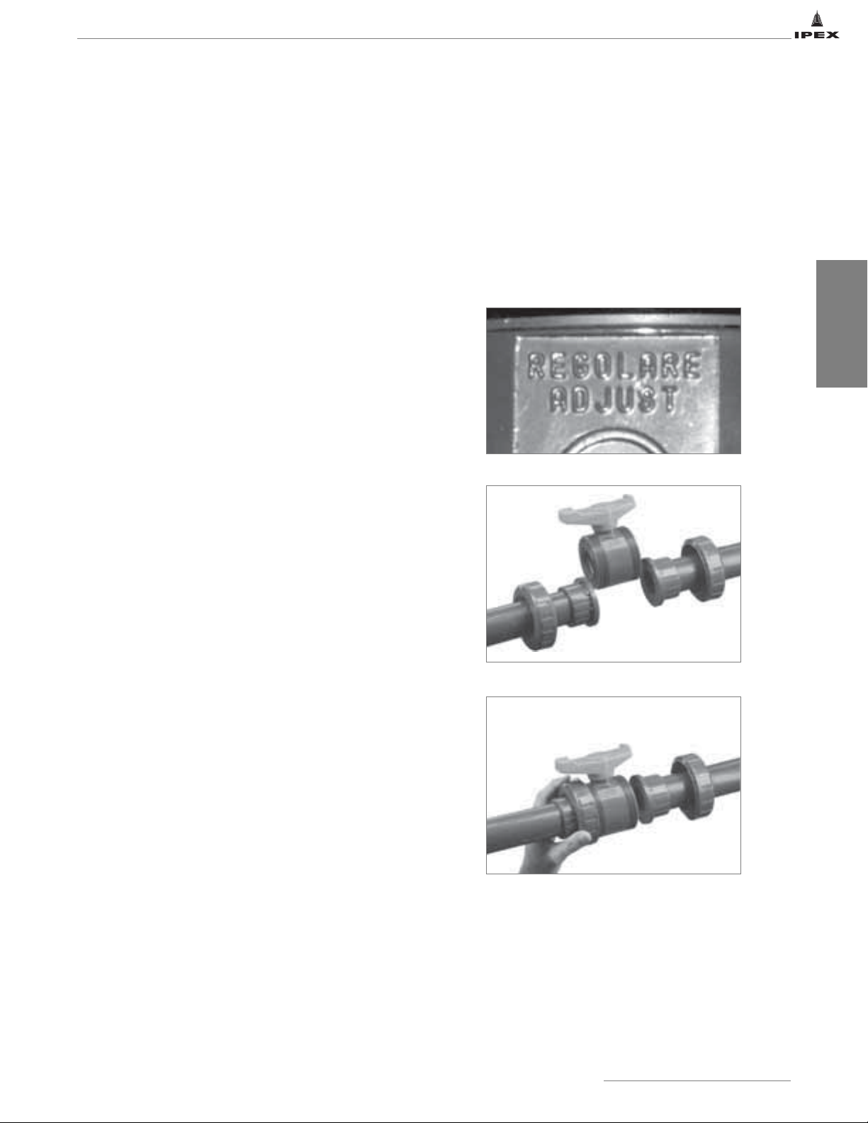
5. Tighten the union nut on the side opposite to that which
is marked "ADJUST". Hand tightening is typically
sufficient to maintain a seal for the maximum working
pressure. Over-tightening may damage the threads on
the valve body and/or the union nut, and may even
cause the union nut to crack.
in the IPEX Industrial
“Volume I: Vinyl Process
.
“Joining
6. Tighten the union nut on the side marked "ADJUST".
Tightening the union nuts in this order results in the best
possible valve performance due to optimum positioning
and sealing of the ball and seat support system.
7. Open and close the valve to again ensure that the
cycling performance is adequate. If adjustment is
required, place the valve in the closed position, loosen
the union nuts, remove the valve from the system, and
then continue from Step 3.
®
8. Engage the Dual Block
piece (16, sizes 1/2" to 2") to the side of the valve body
or by turning the red knob (27, sizes 2-1/2" to 4") to the
locked position. This feature will prevent back-off of the
union nuts during operation.
16
IPEX Thermoplastic Valves
CAUTION: Do not use or test the products in this manual with compressed air or other gases including air-over-water-boosters.
system by affixing the molded
2-1/2" - 4" Dual Block®Mechanism
1/2" - 2" Dual Block®Mechanism
Page 24

VKD SERIES BALL VALVES
Valve Maintenance
Disassembly Assembly
1. If removing the valve from an operating system, isolate
the valve from the rest of the line. Be sure to
depressurize and drain the valve and isolated branch.
2. If necessary, detach the valve from the support structure
by disassembling the connections to the bracket on the
optional bottom of the valve body (7).
®
3. Unlock the Dual Block
system by compressing the two
ends of the molded piece (16, sizes 1/2" to 2") or by
turning the red knob (27, sizes 2-1/2" to 4") to the
unlocked position. Loosen both union nuts (13) and drop
the valve out of the line. If retaining the socket o-rings
(10), take care that they are not lost when removing the
valve from the line.
4. Place the valve in the open position then line up the
moldings on the wrench tool (1, sizes 1/2" to 2") with the
slots in the carrier (found on the side marked “ADJUST”).
Loosen and remove the carrier (11 or 16).
5. Carefully press the ball (6) out of the valve body, taking
care not to score or damage the outer surface.
6. Remove the handle (2) by pulling upwards (sizes 1/2" to
2") or by removing the protective cap (1), bolt (3) and
washer (4) (sizes 2-1/2" to 4").
7. On sizes 2-1/2" to 4", remove the throttling pad (22) by
loosening and removing the bolts (11), washers (14),
nuts (15), and caps (23).
8. Press the stem (4 or 20) into the valve body from above
On sizes 2-1/2" to 4", remove the lower stem (21) by
pushing it into the valve body from below.
9. The stem o-rings (3 or 18), body o-ring (9), ball seats
(5), ball seat o-rings (8), and bushings (19, sizes 2-1/2"
to 4") can now be removed and/or replaced.
Note: It is not typically necessary to disassemble the Dual
®
components (sizes 2-1/2" to 4").
Block
Note: Before assembling the valve components, it is advisable
to lubricate the o-rings with a water soluble lubricant. Be sure
to consult the
trusted resources to determine specific lubricant-rubber
compatibilities.
1. Replace the stem o-rings (3 or 18), body o-ring (9), ball
seat o-rings (8), ball seats (5), and bushings (19, sizes
2-1/2" to 4") in their proper positions.
2. Insert the stem (4 or 20) into position from inside the
valve body (7). On sizes 2-1/2" to 4", insert the lower
stem (21) as well.
3. On sizes 2-1/2" to 4", replace the throttling pad (22) and
affix in position using the bolts (11), washers (14), and
nuts (15). Replace the caps (23) over the nuts.
4. Replace the handle (2). On sizes 2-1/2" to 4", affix using
the bolt (3) and washer (4), then replace the protective
cap (1).
5. Carefully insert the ball (6) into the valve body, taking
care not to score or damage the outer surface. Ensure
that the valve handle and ball position correspond to the
same operating position.
6. Insert the threaded carrier (11 or 16) and tighten into
the valve body. Use the wrench tool to sufficiently
tighten.
7. Place the end connectors (12) into the union nuts (13),
then thread onto the valve body taking care that the
socket o-rings remain properly fitted in their grooves.
8. Engage the Dual Block
piece (16, sizes 1/2" to 2") to the side of the valve body
or by turning the red knob (27, sizes 2-1/2" to 4") to the
locked position.
“IPEX Chemical Resistance Guide”
®
system by affixing the molded
and/or other
BALL VALVES
Operating Notes
The VKD handle incorporates a locking mechanism that
prevents unintentional rotation. When engaged, the springloaded handle release is locked and the valve cannot be
cycled. A padlock can be installed through this portion of
the handle as an additional safety precaution.
Sizes 2-1/2"
Sizes 3" & 4"
IPEX Thermoplastic Valves
CAUTION: Do not use or test the products in this manual with compressed air or other gases including air-over-water-boosters.
17
Page 25
VX SERIES BALL VALVES
IPEX VX Series Ball Valves are ideal for general purpose and
O.E.M. applications. These valves feature an ultra-compact
double block design, and full port bi-directional operation.
The true union design allows the valve to be easily removed
from the piping system and fully serviced. A threaded seat
stop carrier provides improved seal integrity under tough
service conditions while the removable handle also
functions as a tool for ball seat adjustment. VX Series Ball
Valves are part of our complete Xirtec
®
140 and Corzan
systems of pipe, valves, and fittings, engineered and
manufactured to our strict quality, performance, and
dimensional standards.
BALL VALVES
ASTM D1784
ASTM D2464
ASTM D2466
ASTM D2467
ASTM F437
ASTM F439
ASTM F1498
ANSI B1.20.1
ANSI B16.5
Valve Availability
Body Material: PVC, CPVC
Size Range: 1/2" through 6"
Pressure: 232psi (1/2" to 2")
150psi (2-1/2" to 6")
®
Seats: Teflon
Seals: EPDM or Viton®(FPM)
End Connections: Socket (IPS)
®
Threaded (FNPT)
Flanged (ANSI 150)
(PTFE)
18
IPEX Thermoplastic Valves
CAUTION: Do not use or test the products in this manual with compressed air or other gases including air-over-water-boosters.
Page 26

VX SERIES BALL VALVES
Sample Specification
1.0 Ball Valves - VX
1.1 Material
• The valve body, stem, ball and unions shall be made of
PVC compound which shall meet or exceed the
requirements of cell classification 12454 according to
ASTM D1784.
or The valve body, stem, ball and unions shall be made of
1.2 Seats
• The ball seats shall be made of Teflon
1.3 Seals
• The o-ring seals shall be made of EPDM.
or The o-ring seals shall be made of Viton
1.4 All wetted parts of the valves shall comply with
2.0 Connections
2.1 Socket style
• The IPS socket PVC end connectors shall conform to
or The IPS socket CPVC end connectors shall conform to
2.2 Threaded style
• The female NPT threaded PVC end connectors shall
or The female NPT threaded CPVC end connectors shall
2.3 Flanged style
• The ANSI 150 flanged PVC end connectors shall
or The ANSI 150 flanged CPVC end connectors shall
®
Corzan
CPVC compound which shall meet or exceed
the requirements of cell classification 23447
according to ASTM D1784.
®
(PTFE).
®
(FPM).
standards that are equivalent to NSF Standard 61 for
potable water.
the dimensional standards ASTM D2466 and ASTM
D2467.
the dimensional standard ASTM F439.
conform to the dimensional standards ASTM D2464,
ASTM F1498, and ANSI B1.20.1.
conform to the dimensional standards ASTM F437,
ASTM F1498, and ANSI B1.20.1.
conform to the dimensional standard ANSI B16.5.
conform to the dimensional standard ANSI B16.5.
3.0 Design Features
• The valve shall be double blocking with union ends.
• All sizes ½" through 4" shall be full port.
• All sizes shall allow for bi-directional flow.
• The valve body shall be single end entry with a
threaded carrier (ball seat support).
3.0 Design Features
• The valve body shall have an expansion and contraction
compensating groove on the molded end.
• The valve body, union nuts, and carrier shall have deep
square style threads for increased strength.
• The ball shall be machined smooth to minimize wear
on valve seats.
• The stem design shall feature a shear point above the
o-ring to maintain system integrity in the unlikely event
of a stem breakage.
• The handle shall incorporate a tool for adjustment of
the threaded carrier.
• The handle shall be reversible to allow for operation in
tight places.
3.1 Pressure Tested
• All valves shall have been pressure tested in both the
open and closed positions by the manufacturer.
3.2 Pressure Rating
• Valve sizes ½" through 2" shall be rated at 232psi
at 73°F (23ºC).
• Valve sizes 2½" through 6" shall be rated at 150psi
at 73°F (23ºC).
• All sizes of flanged valves shall be rated at 150psi
at 73°F (23ºC).
3.3 Markings
• All valves shall be marked to indicate size, material
designation, and manufacturers name or trade mark.
3.4 Color Coding
• All PVC valves shall be color-coded dark gray.
or All CPVC valves shall be color-coded light gray.
®
4.0 All valves shall be Xirtec
140 or Corzan®by IPEX or
approved equal.
BALL VALVES
IPEX Thermoplastic Valves
CAUTION: Do not use or test the products in this manual with compressed air or other gases including air-over-water-boosters.
19
Page 27
BALL VALVES
VX SERIES BALL VALVES
Dimensions
IPS Socket Connections - Dimension (inches)
Size d L Z H E B C
1/2 0.84 0.89 2.01 3.78 2.09 1.97 2.56
3/4 1.05 1.00 2.13 4.13 2.44 2.28 2.99
1 1.32 1.13 2.34 4.61 2.80 2.56 3.35
1-1/4 1.66 1.26 2.83 5.35 3.31 2.99 3.94
1-1/2 1.90 1.38 3.03 5.79 3.86 3.35 4.41
2 2.38 1.50 3.84 6.85 4.61 4.06 5.39
2-1/2 2.88 1.75 5.00 8.50 6.06 5.24 8.74
3 3.50 1.89 5.47 9.25 7.44 6.06 10.63
4 4.50 2.26 7.64 12.17 8.70 6.89 10.63
*6 6.63 3.03 19.59 25.65 8.70 6.89 10.63
*The 6" valve is a 4" with venturied ends.
Female NPT Threaded Connections - Dimension (inches)
Size R L Z H E B C
1/2 1/2-NPT 0.70 2.14 3.54 2.09 1.97 2.56
3/4 3/4-NPT 0.71 2.24 3.66 2.44 2.28 2.99
1 1-NPT 0.89 2.55 4.33 2.80 2.56 3.35
1-1/4 1-1/4-NPT 0.99 3.02 5.00 3.31 2.99 3.94
1-1/2 1-1/2-NPT 0.97 3.21 5.16 3.86 3.35 4.41
2 2-NPT 1.17 4.01 6.34 4.61 4.06 5.39
3 3-NPT 1.40 6.81 9.61 7.44 6.06 10.63
4 4-NPT 1.48 9.20 12.17 8.70 6.89 10.63
20
ANSI 150 Flanged (Vanstone) Connections - Dimension (inches)
Size # holes f F H B C
1/2 4 5/8 2-3/8 5.59 1.97 2.56
3/4 4 5/8 2-3/4 6.07 2.28 2.99
1 4 5/8 3-1/8 6.74 2.56 3.35
1-1/4 4 5/8 3-1/2 7.54 2.99 3.94
1-1/2 4 5/8 3-7/8 8.29 3.35 4.41
2 4 3/4 4-3/4 9.60 4.06 5.39
2-1/2 4 3/4 5-1/2 11.13 5.24 8.74
3 4 3/4 6 11.74 6.06 10.63
4 8 3/4 7-1/2 14.99 6.89 10.63
*6 8 7/8 9-1/2 28.55 6.89 10.63
*The 6" valve is a 4" with venturied ends.
IPEX Thermoplastic Valves
CAUTION: Do not use or test the products in this manual with compressed air or other gases including air-over-water-boosters.
Page 28
VX SERIES BALL VALVES
Working Temperature (˚F)
Working Pressure (psi)
PVC
CPVC
1/2" to 2"
73
140
232
1/2"
3/4"1"1-1/4"
1-1/2"2"2-1/2"
3"
4" & 6"
Flowrate (GPM)
Pressure loss (psi)
Weights Flow Coefficients
Approximate Weight (lbs)
Size
(inches)
IPS Socket
PVC CPVC
FNPT
Threaded
ANSI
Flanged
IPS
Socket
Threaded
FNPT
ANSI
Flanged
1/2 0.32 0.32 0.72 0.34 0.34 0.76
3/4 0.49 0.49 1.07 0.53 0.53 1.13
1 0.69 0.69 1.48 0.76 0.76 1.58
1-1/4 1.11 1.11 2.11 1.22 1.22 2.22
1-1/2 1.60 1.60 2.80 1.75 1.75 3.02
2 2.74 2.74 4.62 3.02 3.02 5.02
2-1/2 5.73 N/A 8.31 6.27 N/A 9.35
3 9.55 9.55 13.29 10.45 10.45 14.40
4 16.42 16.42 22.42 17.97 17.97 24.30
*6 25.02 N/A 35.04 27.14 N/A 37.73
*The 6" valve is a 4" with venturied ends.
Pressure – Temperature Ratings Pressure Loss Chart
250
Size
C
V
1/2 14.0
3/4 27.0
1 53.9
1-1/4 77.0
1-1/2 123
2 238
2-1/2 368
3 497
4 665
6 665*
*Not including venturied ends.
BALL VALVES
200
2-1/2" to 6"
150
100
50
0
32 62 92 122 152 182 212
10
1
0.1
0.01
1 10 100 1000
IPEX Thermoplastic Valves
CAUTION: Do not use or test the products in this manual with compressed air or other gases including air-over-water-boosters.
21
Page 29
BALL VALVES
VX SERIES BALL VALVES
Components
22
# Component Material Qty
1* handle High Impact PVC
2* stem o-ring EPDM or Viton
®
3* stem PVC / CPVC 1
4 body PVC / CPVC 1
5 ball PVC / CPVC 1
6* body o-ring EPDM or Viton
®
7* end connector PVC / CPVC 2
8 support for ball seat PVC / CPVC 1
9* ball seat PTFE 2
10* socket o-ring EPDM or Viton
®
11* union nut PVC / CPVC 2
* Spare parts available.
IPEX Thermoplastic Valves
CAUTION: Do not use or test the products in this manual with compressed air or other gases including air-over-water-boosters.
1
1
1
2
Page 30
VX SERIES BALL VALVES
Installation Procedures
1. For socket and threaded style connections, remove the
union nuts (part #11 on previous page) and slide them
onto the pipe. For flanged connections, remove the union
nut / flange assemblies from the valve.
6. Tighten the union nut on the side marked “ADJUST”.
Tightening the union nuts in this order results in the best
possible valve performance due to optimum positioning
and sealing of the ball and seat support system.
2. Please refer to the appropriate connection style subsection:
a. For socket style, solvent cement the end connectors
(7) onto the pipe ends. For correct joining
procedure, please refer to the section entitled,
“Joining Methods – Solvent Cementing”
Industrial Technical Manual Series,
Process Piping Systems”
sufficient cure time before continuing with the
valve installation.
b. For threaded style, thread the end connectors (7)
onto the pipe ends. For correct joining procedure,
please refer to the section entitled,
Methods – Threading”
Technical Manual Series,
Piping Systems”
c. For flanged style, join the union nut / flange
assemblies to the pipe flanges. For correct joining
procedure, please refer to the section entitled,
.
“Joining Methods – Flanging”
Technical Manual Series,
Piping Systems”
3. Open and close the valve to ensure that the ball seat
support (8) is at the desired adjustment. If adjustment is
required, ensure that the valve is in the closed position
then remove the handle (1) from the valve stem. Line up
the moldings on the handle with the slots in the ball seat
support. Tighten or loosen to the desired position then
replace the handle on the valve stem.
.
. Be sure to allow
in the IPEX Industrial
“Volume I: Vinyl Process
in the IPEX Industrial
“Volume I: Vinyl Process
in the IPEX
“Volume I: Vinyl
“Joining
7. Open and close the valve to again ensure that the cycling
performance is adequate. If adjustment is required,
place the valve in the closed position, loosen the union
nuts, remove the valve from system and then continue
from Step 3.
BALL VALVES
4. Ensure that the valve is in the closed position, and that
the socket o-rings (10) are properly fitted in their
grooves. Carefully place the valve in the system between
the two end connections.
5. Tighten the union nut on the side opposite to that which
is marked “ADJUST”. Hand tightening is typically
sufficient to maintain a seal for the maximum working
pressure. Over-tightening may damage the threads on the
valve body and/or the union nut and may even cause the
union nut to crack.
IPEX Thermoplastic Valves
CAUTION: Do not use or test the products in this manual with compressed air or other gases including air-over-water-boosters.
23
Page 31

Valve Maintenance
VX SERIES BALL VALVES
Disassembly
1. If removing the valve from an operating system, isolate
the valve from the rest of the system. Be sure to
depressurize and drain the isolated branch and valve
before continuing.
2. Loosen both union nuts (11) and drop the valve out of
the line. If retaining the socket o-rings (10), take care
that they are not lost when removing the valve from
the line.
3. To disassemble, place the valve in the closed position
BALL VALVES
then remove the handle (1) from the valve stem.
4. Line up the moldings on the handle with the slots in the
ball seat support (found on the side marked "ADJUST").
Loosen and remove the ball seat support (8) by turning
in a counterclockwise direction.
5. Carefully press the ball (5) out of the valve body, taking
care not to score or damage the outer surface.
6. To remove the stem (3), press it into the valve body (4)
from above.
7. The stem o-ring (2), body o-ring (6), and ball seats (9)
can now be removed and/or replaced.
Assembly
Note: Before assembling the valve components, it is advisable
to lubricate the o-rings with a water soluble lubricant. Be
sure to consult the
and/or other trusted resources to determine specific
lubricant-rubber compatibilities.
1. Firmly place the ball seat (9) in the groove on the
opposite end inside the valve body (4).
2. Properly fit the stem o-ring (2) in the groove on the stem
(3), then insert the stem from the inside of the valve
body.
3. Ensure that the valve stem is in the closed position then
insert the ball (5) into the valve body taking care not to
score or damage the outer surface.
4. Check that the ball seat (9) and body o-ring (6) are
properly fitted on the ball seat support (8), then slightly
hand tighten into the valve body. Line up the moldings
on the handle (1) with the slots in the ball seat support
then tighten by turning in a clockwise direction.
5. Replace the handle on the valve stem then cycle the
valve open and closed to determine whether or not the
performance is adequate. If so desired, the handle can
be removed and used to make further adjustments.
“IPEX Chemical Resistance Guide”
6. Properly fit the socket o-rings (10) in their respective
grooves.
7. Place the end connectors (7) into the union nuts (11),
then thread onto the valve body taking care that the
socket o-rings remain properly fitted
in their grooves.
24
IPEX Thermoplastic Valves
CAUTION: Do not use or test the products in this manual with compressed air or other gases including air-over-water-boosters.
Page 32

VE SERIES BALL VALVES
IPEX VE Series Ball Valves are ideal for light industrial and
water applications. These valves feature an ultra-compact
double block design, and full port bi-directional operation. The
true union design allows the valve to be easily removed from
the piping system and fully serviced. A threaded seat stop
carrier provides improved seal integrity under tough service
conditions while the removable handle also functions as a tool
for ball seat adjustment. VE Series Ball Valves are part of our
complete Xirtec
®
140 systems of pipe, valves, and fittings,
engineered and manufactured to our strict quality,
performance, and dimensional standards.
ASTM D1784
ASTM D2464
ASTM D2466
ASTM D2467
ASTM F1498
ANSI B1.20.1
Valve Availability
Body Material: PVC
Size Range: 1/2" through 2"
Pressure: 232psi
Seats: Teflon
Seals: EPDM
End Connections: Socket (IPS)
®
(PTFE) – HDPE blend
Threaded (FNPT)
BALL VALVES
IPEX Thermoplastic Valves
CAUTION: Do not use or test the products in this manual with compressed air or other gases including air-over-water-boosters.
25
Page 33

BALL VALVES
VE SERIES BALL VALVES
Sample Specification
1.0 Ball Valves - VE
1.1 Material
• The valve body, stem, ball and unions shall be made of
PVC compound which shall meet or exceed the
requirements of cell classification 12454 according to
ASTM D1784.
1.2 Seats
®
• The ball seats shall be made of a Teflon
HDPE blend.
1.3 Seals
• The o-ring seals shall be made of EPDM.
1.4 All wetted parts of the valves shall comply with
standards that are equivalent to NSF Standard 61 for
potable water.
2.0 Connections
2.1 Socket style
• The IPS socket PVC end connectors shall conform to
the dimensional standards ASTM D2466 and ASTM
D2467.
2.2 Threaded style
• The female NPT threaded PVC end connectors shall
conform to the dimensional standards ASTM D2464,
ASTM F1498, and ANSI B1.20.1.
(PTFE) –
3.0 Design Features
• The valve shall be double blocking with union ends.
• All sizes shall be full port.
• All sizes shall allow for bi-directional flow.
• The valve body shall be single end entry with a
threaded carrier (ball seat support).
• The valve body shall have an expansion and contraction
compensating groove on the molded end.
• The valve body, union nuts, and carrier shall have deep
square style threads for increased strength.
• The ball shall be machined smooth to minimize wear
on valve seats.
• The stem design shall feature a shear point above the
o-ring to maintain system integrity in the unlikely event
of a stem breakage.
• The handle shall incorporate a tool for adjustment of
the threaded carrier.
• The handle shall be reversible to allow for operation in
tight places.
3.1 Pressure Tested
• All valves shall have been pressure tested in both the
open and closed positions by the manufacturer.
3.2 Pressure Rating
• All sizes shall be rated at 232psi at 73°F (23ºC).
3.3 Markings
• All valves shall be marked to indicate size, material
designation, and manufacturers name or trade mark.
3.4 Color Coding
• All PVC valves shall be color-coded dark gray with a
blue handle.
®
4.0 All valves shall be Xirtec
140 by IPEX or approved equal.
26
IPEX Thermoplastic Valves
CAUTION: Do not use or test the products in this manual with compressed air or other gases including air-over-water-boosters.
Page 34

Working Temperature (˚F)
Working Pressure (psi)
PVC
73
140
232
3/4"
1"
1-1/4"
1-1/2"
2"
Flowrate (GPM)
Pressure loss (psi)
Dimensions
VE SERIES BALL VALVES
IPS Socket Connections - Dimension (inches)
Size d L Z H E B C
1/2 0.84 0.89 2.01 3.78 2.09 1.97 2.56
3/4 1.05 1.00 2.13 4.13 2.44 2.28 2.99
1 1.32 1.13 2.34 4.61 2.80 2.56 3.35
1-1/4 1.66 1.26 2.83 5.35 3.31 2.99 3.94
1-1/2 1.90 1.38 3.03 5.79 3.86 3.35 4.41
2 2.38 1.50 3.84 6.85 4.61 4.06 5.39
Female NPT Threaded Connections - Dimension (inches)
Size R L Z H E B C
1/2 1/2-NPT 0.70 2.14 3.54 2.09 1.97 2.56
3/4 3/4-NPT 0.71 2.24 3.66 2.44 2.28 2.99
1 1-NPT 0.89 2.55 4.33 2.80 2.56 3.35
1-1/4 1-1/4-NPT 0.99 3.02 5.00 3.31 2.99 3.94
1-1/2 1-1/2-NPT 0.97 3.21 5.16 3.86 3.35 4.41
2 2-NPT 1.17 4.01 6.34 4.61 4.06 5.39
BALL VALVES
Weights
Approximate Weight (lbs)
Size
(inches)
IPS Socket FNPT Threaded
1/2 0.32 0.32
3/4 0.49 0.49
1 0.69 0.69
1-1/4 1.11 1.11
1-1/2 1.60 1.60
2 2.74 2.74
Pressure – Temperature Ratings
250
200
150
100
50
PVC
Flow Coefficients
Size
1/2 14.0
3/4 27.0
1 53.9
1-1/4 77.0
1-1/2 123
2 238
Pressure Loss Chart
10
1
0.1
C
V
1/2"
0
32 62 92 122 152 182 212
CAUTION: Do not use or test the products in this manual with compressed air or other gases including air-over-water-boosters.
0.01
1 10 100 1000
IPEX Thermoplastic Valves
27
Page 35

BALL VALVES
VE SERIES BALL VALVES
Components
28
# Component Material Qty
1 handle High Impact PVC 1
2 stem o-ring EPDM 1
3 stem PVC 1
4 body PVC 1
5 ball PVC 1
6 body o-ring EPDM 1
7* end connector PVC 2
8 support for ball seat PVC 1
9 ball seat PTFE – HDPE blend 2
10 socket o-ring EPDM 2
11* union nut PVC 2
* Spare parts available
IPEX Thermoplastic Valves
CAUTION: Do not use or test the products in this manual with compressed air or other gases including air-over-water-boosters.
Page 36

VE SERIES BALL VALVES
Installation Procedures
1. Remove the union nuts (part #11 on previous page) and
slide them onto the pipe.
2. Please refer to the appropriate connection style subsection:
a. For socket style, solvent cement the end connectors
(7) onto the pipe ends. For correct joining
procedure, please refer to the section entitled,
“Joining Methods – Solvent Cementing”
Industrial Technical Manual Series,
Process Piping Systems”
sufficient cure time before continuing with the
valve installation.
b. For threaded style, thread the end connectors (7)
onto the pipe ends. For correct joining procedure,
please refer to the section entitled,
Methods – Threading”
Technical Manual Series, “Volume I: Vinyl Process
Piping Systems”.
3. Open and close the valve to ensure that the ball seat
support (8) is at the desired adjustment. If adjustment is
required, ensure that the valve is in the closed position
then remove the handle (1) from the valve stem. Line up
the moldings on the handle wit the slots in the ball seat
support. Tighten or loosen to the desired position then
replace the handle on the valve stem.
. Be sure to allow
in the IPEX Industrial
in the IPEX
“Volume I: Vinyl
“Joining
BALL VALVES
4. Ensure that the valve is in the closed position, and that
the socket o-rings (10) are properly fitted in their
grooves. Carefully place the valve in the system between
the two end connections.
5. Tighten the union nut on the side opposite to that which
is marked “ADJUST”. Hand tightening is typically
sufficient to maintain a seal for the maximum working
pressure. Over-tightening may damage the threads on the
valve body and/or the union nut and may even cause the
union nut to crack.
6. Tighten the union nut on the side marked “ADJUST”.
Tightening the union nuts in this order results in the best
possible valve performance due to optimum positioning
and sealing of the ball and seat support system.
7. Open and close the valve to again ensure that the cycling
performance is adequate. If adjustment is required,
place the valve in the closed position, loosen the union
nuts, remove the valve from system and then continue
from Step 3.
IPEX Thermoplastic Valves
CAUTION: Do not use or test the products in this manual with compressed air or other gases including air-over-water-boosters.
29
Page 37

Valve Maintenance
VE SERIES BALL VALVES
Disassembly
1. If removing the valve from an operating system, isolate
the valve from the rest of the system. Be sure to
depressurize and drain the isolated branch and valve
before continuing.
2. Loosen both union nuts (11) and drop the valve out of
the line. If retaining the socket o-rings (10), take care
that they are not lost when removing the valve from the
line.
3. To disassemble, place the valve in the closed position
then remove the handle (1) from the valve stem.
BALL VALVES
4. Line up the moldings on the handle with the slots in the
ball seat support (found on the side marked “ADJUST”).
Loosen and remove the ball seat support (8) by turning
in a counterclockwise direction.
5. Carefully press the ball (5) out of the valve body, taking
care not to score or damage the outer surface.
6. To remove the stem (3), press it into the valve body (4)
from above.
7. The stem o-ring (2), body o-ring (6), and ball seats (9)
can now be removed and/or replaced.
Assembly
Note: Before assembling the valve components, it is advisable
to lubricate the o-rings with a water soluble lubricant. Be
sure to consult the
and/or other trusted resources to determine specific
lubricant-rubber compatibilities.
1. Firmly place the ball seat (9) in the groove on the
opposite end inside the valve body (4).
2. Properly fit the stem o-ring (2) in the groove on the stem
(3), then insert the stem from the inside of the valve
body.
3. Ensure that the valve stem is in the closed position then
insert the ball (5) into the valve body taking care not to
score or damage the outer surface.
4. Check that the ball seat (9) and body o-ring (6) are
properly fitted on the ball seat support (8), then slightly
hand tighten into the valve body. Line up the moldings
on the handle (1) with the slots in the ball seat support
then tighten by turning in a clockwise direction.
5. Replace the handle on the valve stem then cycle the
valve open and closed to determine whether or not the
performance is adequate. If so desired, the handle can
be removed and used to make further adjustments.
“IPEX Chemical Resistance Guide”
6. Properly fit the socket o-rings (10) in their respective
grooves.
7. Place the end connectors (7) into the union nuts (11),
then thread onto the valve body taking care that the
socket o-rings remain properly fitted
in their grooves.
30
IPEX Thermoplastic Valves
CAUTION: Do not use or test the products in this manual with compressed air or other gases including air-over-water-boosters.
Page 38

MP SERIES COMPACT BALL VALVES
IPEX MP Series Compact Ball Valves are ideally suited to all
kinds of plumbing and industrial applications where a
compact, inexpensive on/off valve is required. The simple
one piece PVC body with integral end connections eliminates
potential problems cause by improper adjustment of the ball
seating. MP Series Compact Ball Valves are part of our
complete Xirtec
®
140 systems of pipe, valves, and fittings,
engineered and manufactured to our strict quality,
performance, and dimensional standards.
ASTM D1784
ASTM D2464
ASTM D2466
ASTM D2467
ASTM F1498
ANSI B1.20.1 NSF 14/61
Valve Availability
Body Material: PVC
Size Range: 1/2" through 2"
Pressure: 150psi
Seats: Teflon®(PTFE)
Seals: EPDM
End Connections: Socket (IPS)
Threaded (FNPT)
BALL VALVES
IPEX Thermoplastic Valves
CAUTION: Do not use or test the products in this manual with compressed air or other gases including air-over-water-boosters.
31
Page 39

Sample Specification
1.0 Ball Valves - MP
MP SERIES COMPACT BALL VALVES
BALL VALVES
1.1 Material
• The valve body and ball shall be made of PVC
compound which shall meet or exceed the requirements
of cell classification 12454 according to ASTM D1784.
1.2 Seats
• The ball seats shall be made of Teflon
®
(PTFE).
1.3 Seals
• The o-ring seals shall be made of EPDM.
1.4 All wetted parts of the valves shall comply with NSF
Standard 14/61 for potable water.
2.0 Connections
2.1 Socket style
• The IPS socket PVC end connections shall conform to the
dimensional standards ASTM D2466 and ASTM D2467.
2.2 Threaded style
• The female NPT threaded PVC end connections shall
conform to the dimensional standards ASTM D2464,
ASTM F1498, and ANSI B1.20.1.
3.0 Design Features
• The valve shall be composed of a one piece PVC body.
• The end connections shall be an integral part of the body.
• All sizes shall allow for bi-directional flow.
3.1 Pressure Rating
• All sizes shall be rated at 150psi at 73°F (23ºC) (nonshock).
3.2 Markings
• All valves shall be marked to indicate size, material
designation, and manufacturers name or trade mark.
3.3 Color Coding
• All PVC Schedule 40 valves shall be color-coded white.
• All PVC Schedule 80 valves shall be color-coded dark gray.
®
4.0 All valves shall be Xirtec
140 by IPEX or approved equal.
Dimensions and Weights
A
D2
D1
L
Flow Coefficients
Size
1/2 8.80
3/4 13.2
1 25.2
1-1/4 38.5
1-1/2 51.3
2 96.7
Dimension (inches)
Size D1
H
1/2 0.59 0.84 1/2 NPT 0.88 3.11 1.38 1.85 2.76 0.24
d
Socketd Threaded
P L D2 H A W (lbs)
3/4 0.79 1.05 3/4 NPT 1.00 3.54 1.58 2.24 3.03 0.35
1 0.98 1.32 1 NPT 1.13 4.13 1.89 2.40 3.50 0.52
P
1-1/4 1.26 1.66 1-1/4 NPT 1.25 4.76 2.13 2.60 3.50 0.74
1-1/2 1.54 1.90 1-1/2 NPT 1.38 5.00 2.44 2.91 4.37 1.06
2 1.97 2.38 2 NPT 1.50 5.87 2.95 3.15 5.47 1.72
C
V
32
IPEX Thermoplastic Valves
CAUTION: Do not use or test the products in this manual with compressed air or other gases including air-over-water-boosters.
Page 40

MP SERIES COMPACT BALL VALVES
0.01
0.1
1
10
1 10 100 1000
1/2"
3/4"
1"
1-1/4"
1-1/2"
2"
Working Temperature (˚F)
Working Pressure (psi)
73
140
PVC 1/2" to 2"
Pressure – Temperature Ratings
250
200
150
100
50
0
32 62 92 122 152 182 212
Pressure Loss Chart
BALL VALVES
Pressure loss (psi)
Flowrate (GPM)
# Component Material Qty
1 stem PVC
2 ball PVC 1
3 body PVC (white) / PVC (gray)
4 stem o-ring EPDM 1
5 cap ABS
6 handle ABS 1
7 seat PTFE 2
CAUTION: Do not use or test the products in this manual with compressed air or other gases including air-over-water-boosters.
1
1
1
IPEX Thermoplastic Valves
33
Page 41

MP SERIES COMPACT BALL VALVES
Installation Procedures
1. Please refer to the appropriate connection style subsection:
a. For socket style, solvent cement each pipe end into
the body of the valve. For correct joining procedure,
please refer to the section entitled,
Methods – Solvent Cementing”
Industrial Technical Manual Series,
BALL VALVES
Process Piping Systems”
cure time before pressurizing the system.
b. For threaded style, thread each pipe end into the
body of the valve. For correct joining procedure,
please refer to the section entitled,
Methods – Threading”
Technical Manual Series,
Piping Systems”
.
. Be sure to allow sufficient
in the IPEX Industrial
“Volume I: Vinyl Process
“Joining
in the IPEX
“Volume I: Vinyl
“Joining
Removal From the System
1. If removing the valve from an operating system, isolate
the valve from the rest of the system. Be sure to
depressurize and drain the isolated branch and valve
before continuing.
2. Please refer to the appropriate connection style subsection:
a. For socket style, cut the pipe as close to the ends of
the valve body as possible. The valve can now be
replaced.
b. For threaded style, unthread the pipe ends from the
valve body. The valve can now be reused and/or
replaced.
Note: The MP Compact Ball Valve is a molded-in-place
valve. It cannot be disassembled.
34
IPEX Thermoplastic Valves
CAUTION: Do not use or test the products in this manual with compressed air or other gases including air-over-water-boosters.
Page 42

TK SERIES 3-WAY BALL VALVES
IPEX TK Series 3-Way Ball Valves can be used for flow
diverting, mixing, or on/off isolation. They will replace a Tee
+ 2 valve linkage assembly at reduced cost and space, along
with shorter installation and maintenance time. The
patented seat stop carrier allows for in-line microadjustment of the ball seating, and features o-ring
cushioning to minimize wear and prevent seizing. Integral
mounting flange and bracketing allows for direct actuation
and simple support, while a locking handle can prevent
improper positioning. TK Series 3-Way Ball Valves are part of
our complete Xirtec
fittings, engineered and manufactured to our strict quality,
performance, and dimensional standards.
®
140 systems of pipe, valves, and
Valve Availability
Body Material: PVC
Size Range: 1/2" through 2"
Pressure: 232psi
Seats: Teflon
Seals: EPDM or Viton
End Connections: Socket (IPS)
®
(PTFE)
Threaded (FNPT)
®
(FPM)
BALL VALVES
ASTM D1784
ASTM D2464
ASTM D2466
ASTM D2467
ASTM F1498
ANSI B1.20.1
IPEX Thermoplastic Valves
CAUTION: Do not use or test the products in this manual with compressed air or other gases including air-over-water-boosters.
35
Page 43

BALL VALVES
TK SERIES 3-WAY BALL VALVES
Sample Specification
1.0 Ball Valves - TK
1.1 Material
• The valve body, stem, ball, end connectors, and unions
shall be made of PVC compound which shall meet or
exceed the requirements of cell classification 12454
according to ASTM D1784.
1.2 Seats
• The ball seats shall be made of Teflon
1.3 Seals
• The o-ring seals shall be made of EPDM.
or The o-ring seals shall be made of Viton
1.4 All wetted parts of the valves shall comply with
standards that are equivalent to NSF Standard 61 for
potable water.
2.0 Connections
2.1 Socket style
• The IPS socket PVC end connectors shall conform to
the dimensional standards ASTM D2466 and ASTM
D2467.
2.2 Threaded style
• The female NPT threaded PVC end connectors shall
conform to the dimensional standards ASTM D2464,
ASTM F1498, and ANSI B1.20.1.
3.0 Design Features
• All valves shall be true union at all three ports.
• All sizes shall be full port.
• Valve design shall permit positive shutoff of any of the
three ports.
• Balls shall be of T-port or L-port design (specifier must
select one).
• The valve shall have blocking seat supports at all three
ports.
®
(PTFE).
®
(FPM).
• The threaded carrier (ball seat support) shall be
adjustable with the valve installed.
• The valve body, union nuts, and carrier shall have deep
square style threads for increased strength.
• The ball shall be machined smooth to minimize wear
on valve seats.
• All valve seats shall have o-ring backing cushions to
compensate for wear and prevent seizure of the ball.
• The thickness of the valve body shall be the same at
all three ports.
• The stem design shall feature a shear point above the
o-ring to maintain system integrity in the unlikely event
of a stem breakage.
• The handle shall feature a locking mechanism to
prevent unintentional movement.
• The handle shall incorporate a feature to allow the
valve position to be secured with a padlock.
• The handle shall incorporate a removable tool for
adjustment of the threaded carrier.
• The top of the stem shall incorporate molded features
to indicate port location and ball position.
• All valves shall have integrally molded mounting
flanges for support and actuation
3.1 Pressure Rating
• All valves shall be rated at 232psi at 73°F (23ºC).
3.2 Markings
• All valves shall be marked to indicate size, material
designation, and manufacturers name or trade mark.
3.3 Color Coding
• All PVC valves shall be color-coded dark gray.
®
4.0 All valves shall be Xirtec
140 by IPEX or approved
equal.
36
IPEX Thermoplastic Valves
CAUTION: Do not use or test the products in this manual with compressed air or other gases including air-over-water-boosters.
Page 44

Dimensions
TK SERIES 3-WAY BALL VALVES
Dimension (inches)
Size C C1 C2 B B1 B2
1/2 3.29 1.16 2.13 3.44 1.30 1.97
3/4 3.86 1.40 2.46 3.88 1.54 2.22
1 4.13 1.46 2.68 4.17 1.77 2.42
1-1/4 5.49 2.01 3.48 5.31 2.01 3.01
1-1/2 5.49 2.01 3.48 5.47 2.24 3.17
2 6.06 2.01 4.06 6.26 2.72 3.84
IPS Socket Connections - Dimension (inches)
Size d L Z H H1 E
1/2 0.84 0.91 3.43 5.20 3.15 2.17
3/4 1.05 1.00 4.26 6.27 3.94 2.60
1 1.32 1.13 4.59 6.85 4.33 2.95
1-1/4 1.66 1.26 5.55 8.07 5.16 3.43
1-1/2 1.90 1.38 6.20 8.96 5.83 3.94
2 2.38 1.50 7.50 10.51 7.05 4.80
BALL VALVES
sizes 1/2" to 1"
Female NPT Threaded Connections - Dimension (inches)
Size R L Z H H1 E
1/2 1/2-NPT 0.71 3.56 4.96 3.15 2.17
3/4 3/4-NPT 0.71 4.35 5.76 3.94 2.60
1 1-NPT 0.89 4.78 6.56 4.33 2.95
1-1/4 1-1/4-NPT 0.99 5.73 7.71 5.16 3.43
1-1/2 1-1/2-NPT 0.97 6.38 8.32 5.83 3.94
2 2-NPT 1.17 7.66 9.99 7.05 4.80
Mounting Flanges - Dimension (inches)
Size
1/2 0.28 0.38 0.81 1.46 1.00 0.18
3/4 0.31 0.47 0.87 1.65 1.18 0.18
1 0.35 0.49 1.18 1.97 1.32 0.24
1-1/4 0.41 0.53 1.42 2.60 1.57 0.24
1-1/2 0.45 0.57 1.46 2.80 1.69 0.28
2 0.59 0.79 1.77 3.35 1.69 0.28
A
1
A
2
B L H f
sizes 1-1/4" to 2"
IPEX Thermoplastic Valves
CAUTION: Do not use or test the products in this manual with compressed air or other gases including air-over-water-boosters.
37
Page 45

Working Temperature (˚F)
Working Pressure (psi)
PVC
73
140
232
Dimensions (cont’d)
BALL VALVES
Weights
TK SERIES 3-WAY BALL VALVES
Size ISO J P
1/2 F04 0.20 1.65
3/4 F05 0.28 1.97
1 F05 0.28 1.97
1-1/4 F07 0.35 2.76
1-1/2 F07 0.35 2.76
2 F07 0.35 2.76
Approximate Weight (lbs)
Size IPS Socket FNPT Threaded
1/2 0.77 0.77
3/4 1.32 1.32
1 1.87 1.87
1-1/4 2.98 2.98
1-1/2 3.86 3.86
2 6.50 6.50
Dimension (inches)
Flow Coefficients
C
V
Size
A B C D E
1/2 3.85 2.45 4.55 13.7 5.11
3/4 9.50 6.65 10.2 26.6 10.5
1 14.4 9.80 17.2 53.2 18.6
1-1/4 27.3 18.9 32.2 73.5 33.3
1-1/2 33.3 23.1 42.0 119 43.4
2 63.0 43.4 84.0 224 85.4
Position
Pressure - Temperature Ratings
250
200
150
100
50
0
32 62 92 122 152 182 212
38
IPEX Thermoplastic Valves
CAUTION: Do not use or test the products in this manual with compressed air or other gases including air-over-water-boosters.
Page 46

Operating Positions
Position T-Port L-Port
TK SERIES 3-WAY BALL VALVES
T-Port
Position
L-Port
0º mixing diverting
90º diverting closed
180º straight flow closed
270º diverting diverting
0º
BALL VALVES
90º
180º
270º
IPEX Thermoplastic Valves
CAUTION: Do not use or test the products in this manual with compressed air or other gases including air-over-water-boosters.
39
Page 47

Pressure Loss Charts
TK SERIES 3-WAY BALL VALVES
BALL VALVES
Position A:
• T-Port
• Center Inlet
• Diverting Flow
Position B:
• T-Port
• Center Inlet
• Separating Flow
3/4"
10
1
0.1
Pressure loss (psi)
0.01
1 10 100 1000
10
1
0.1
Pressure loss (psi)
Flowrate (GPM)
1/2"
1/2"
3/4"
1"
1-1/4"
1-1/2"
1-1/4"
1"
1-1/2"
2"
2"
Position C:
• T-Port
• Side Inlet
• Diverting Flow
0.01
1 10 100 1000
10
1
0.1
Pressure loss (psi)
0.01
1 10 100 1000
Flowrate (GPM)
Flowrate (GPM)
1/2"
3/4"
1"
1-1/4"
1-1/2"
2"
40
IPEX Thermoplastic Valves
CAUTION: Do not use or test the products in this manual with compressed air or other gases including air-over-water-boosters.
Page 48

TK SERIES 3-WAY BALL VALVES
Pressure Loss Charts
Position D:
• T-Port
• Side Inlet
• Straight Flow
Position E:
• L-Port
• Any Inlet
• Diverting Flow
(cont’d)
1/2"
3/4"
3/4"
1"
10
1
0.1
Pressure loss (psi)
0.01
1 10 100 1000
10
1
Flowrate (GPM)
1/2"
1"
1-1/4"
1-1/4"
1-1/2"
1-1/2"
2"
BALL VALVES
2"
0.1
Pressure loss (psi)
0.01
1 10 100 1000
Flowrate (GPM)
IPEX Thermoplastic Valves
CAUTION: Do not use or test the products in this manual with compressed air or other gases including air-over-water-boosters.
41
Page 49

BALL VALVES
TK SERIES 3-WAY BALL VALVES
Components
42
# Component Material Qty
1* insert tool PVC
2 handle PVC 1
3* stem o-ring EPDM or Viton
®
4 stem PVC 1
5 ball seat PTFE
6 ball PVC 1
7body PVC 1
8* backing o-ring EPDM or Viton
9* body o-ring EPDM or Viton
10* socket o-ring EPDM or Viton
®
®
®
11 support for ball seat PVC 3
12* end connector PVC 3
13* union nut PVC 3
14 blocking button POM 1
15 stop ring PVC 3
* Spare parts available.
IPEX Thermoplastic Valves
CAUTION: Do not use or test the products in this manual with compressed air or other gases including air-over-water-boosters.
1
2
4
4
3
3
Page 50

TK SERIES 3-WAY BALL VALVES
Installation Procedures
1. For socket and threaded style connections, remove the
union nuts (part #13 on previous page) and slide them
onto the pipe. For flanged connections, remove the union
nut / flange assemblies from the valve.
2. Please refer to the appropriate connection style subsection:
a. For socket style, solvent cement the end connectors
(12) onto the pipe ends. For correct joining
procedure, please refer to the section entitled,
“Joining Methods – Solvent Cementing”
Industrial Technical Manual Series,
Process Piping Systems”
sufficient cure time before continuing with the
valve installation.
b. For threaded style, thread the end connectors (12)
onto the pipe ends. For correct joining procedure,
please refer to the section entitled,
Methods – Threading”
Technical Manual Series,
Piping Systems”
3. Open and close the valve to ensure that the seat
supports (11) are at the desired adjustment. If
adjustment is required, remove the insert tool (1) from
the handle (2). Line up the moldings on the tool with the
slots in the seat supports. Tighten or loosen to the
desired position then replace the tool on the handle. For
correct alignment of the ball and seat support system,
adjustment should begin with the center port.
4. Ensure that the socket o-rings (10) are properly fitted in
their grooves then carefully place the valve in the system
between the end connections. If anchoring is required,
fix the valve to the supporting structure via the integral
mounting flange on the bottom of the valve body (7).
.
. Be sure to allow
in the IPEX Industrial
“Volume I: Vinyl Process
in the IPEX
“Volume I: Vinyl
“Joining
BALL VALVES
5. Tighten the three union nuts. Hand tightening is typically
sufficient to maintain a seal for the maximum working
pressure. Over-tightening may damage the threads on the
valve body and/or the union nut, and may even cause the
union nut to crack.
6. Open and close the valve to ensure that the cycling
performance is adequate. If adjustment is required,
loosen the union nuts, remove the valve from the system,
and then continue from Step 3.
IPEX Thermoplastic Valves
CAUTION: Do not use or test the products in this manual with compressed air or other gases including air-over-water-boosters.
43
Page 51

TK SERIES 3-WAY BALL VALVES
Valve Maintenance
Disassembly Assembly
1. If removing the valve from an operating system, isolate
the valve from the rest of the system. Be sure to
depressurize and drain the isolated branch and valve
before continuing.
2. Loosen the three union nuts (13) and drop the valve out of
the line. If retaining the socket o-rings (10), take care that
they are not lost when removing the valve from the line.
3. To disassemble, rotate the handle (2) to the following
position:
BALL VALVES
a. For T-Port valves, the three arrows must line up
with the three valve ports (The valve must be open
at all three ports).
b. For L-Port valves, the two arrows must line up with
ports “a” and “b” (see component diagram).
4. Remove the insert tool (1) from the handle then line up
the moldings on the tool with the slots in the seat
supports (11). Loosen and remove all three seat supports
from the valve body (7).
5. Remove the ball (6) from the valve body while taking
care not to score or damage the outer surface.
6. Remove the handle from the stem (4) by pulling upwards.
To remove the stem, push it into the valve body from above.
7. Remove the seats (5), backing o-rings (8), and body orings (9) from the seat supports.
8. Remove the seat and backing o-ring from the inside of
the valve body.
Note: Before assembling the valve components, it is
advisable to lubricate the o-rings with a water soluble
lubricant. Be sure to consult the
Guide”
lubricant-rubber compatibilities.
1. Properly fit the stem o-rings (3) in the grooves on the
2. Line up the markings on the stem with the ports in the
3. Replace the backing o-ring (8) and seat (5) at the back
4. Insert the ball (6) into the valve body while ensuring that
5. Ensure that all body o-rings (9), backing o-rings, and
6. Replace the handle (2) on the stem while ensuring that
7. Properly fit the socket o-rings (10) in their respective
8. Place the end connectors (12) into the union nuts (13),
and/or other trusted resources to determine specific
stem (4), then insert the stem from the inside of the
valve body (7).
valve body.
of the valve body.
the ports line up with the markings on the stem.
seats are properly fitted on the three seat supports (11).
Starting with the center port, tighten each support into
the valve body using the insert tool (1).
the position markings on the handle line up with those
on the stem. Replace the insert tool on the handle.
grooves.
then thread onto the valve body taking care that the
socket o-rings remain properly fitted in their grooves.
“IPEX Chemical Resistance
9. Remove the stem o-rings (3).
10. The valve components can now be checked for problems
and/or replaced.
44
IPEX Thermoplastic Valves
CAUTION: Do not use or test the products in this manual with compressed air or other gases including air-over-water-boosters.
Page 52

TKD SERIES 3-WAY BALL VALVES
IPEX TKD Series 3-Way Ball Valves can be used for flow
diverting, mixing, or on/off isolation. They will replace a Tee +
2 valve linkage assembly at reduced cost and space, along
with shorter installation and maintenance time. The patented
seat stop carrier allows for in-line microadjustment of the ball
seating, and features o-ring cushioning to minimize wear and
prevent seizing. The TKD also includes our patented DUAL
®
BLOCK
are held in position even under severe service conditions such
as high vibration or thermal expansion. Integral mounting
flange and bracketing allows for direct actuation and simple
support, while a locking handle can prevent improper
positioning. TKD Series 3-Way Ball Valves are part of our
complete Xirtec
engineered and manufactured to our strict quality,
performance, and dimensional standards.
locking union nut system, which ensures the nuts
®
140 systems of pipe, valves and fittings,
Valve Availability
Body Material: PVC
Size Range: 1/2" through 2"
Pressure: 232psi
Seats: Teflon
Seals: EPDM or Viton
End Connections: Socket (IPS)
®
(PTFE)
Threaded (FNPT)
®
(FKM)
BALL VALVES
ASTM D1784
ASTM D2464
ASTM D2466
ASTM D2467
ASTM F1498
ANSI B1.20.1
IPEX Thermoplastic Valves
CAUTION: Do not use or test the products in this manual with compressed air or other gases including air-over-water-boosters.
45
Page 53

BALL VALVES
TKD SERIES 3-WAY BALL VALVES
Sample Specification
1.0 Ball Valves - TKD
1.1 Material
• The valve body, stem, ball, end connectors, and unions
shall be made of PVC compound which shall meet or
exceed the requirements of cell classification 12454
according to ASTM D1784.
1.2 Seats
• The ball seats shall be made of Teflon
1.3 Seals
• The o-ring seals shall be made of EPDM.
or The o-ring seals shall be made of Viton
1.4 All wetted parts of the valves shall comply with
standards that are equivalent to NSF Standard 61 for
potable water.
2.0 Connections
2.1 Socket style
• The IPS socket PVC end connectors shall conform to
the dimensional standards ASTM D2466 and ASTM
D2467.
2.2 Threaded style
• The female NPT threaded PVC end connectors shall
conform to the dimensional standards ASTM D2464,
ASTM F1498, and ANSI B1.20.1.
3.0 Design Features
• All valves shall be true union at all three ports.
• All sizes shall be full port.
• Valve design shall permit positive shutoff of any of the
three ports.
• Balls shall be of T-port or L-port design (specifier must
select one).
• The valve shall have blocking seat supports at all three
ports.
®
(PTFE).
®
(FKM).
• The threaded carrier (ball seat support) shall be
adjustable with the valve installed.
• The valve body, union nuts, and carrier shall have deep
square style threads for increased strength.
• The ball shall be machined smooth to minimize wear
on valve seats.
• All valve seats shall have o-ring backing cushions to
compensate for wear and prevent seizure of the ball.
• The thickness of the valve body shall be the same at
all three ports.
• The stem design shall feature a shear point above the
o-ring to maintain system integrity in the unlikely event
of a stem breakage.
®
• The valve shall include the DUAL BLOCK
union nut
locking mechanism
• The handle shall incorporate an optional feature to
allow the valve position to be secured with a padlock.
• The handle shall incorporate a removable tool for
adjustment of the threaded carrier.
• The top of the stem shall incorporate molded features
to indicate port location and ball position.
• All valves shall have integrally molded mounting
flanges for support and actuation
3.1 Pressure Rating
• All valves shall be rated at 232psi at 73°F (23ºC).
3.2 Markings
• All valves shall be marked to indicate size, material
designation, and manufacturers name or trade mark.
3.3 Color Coding
• All PVC valves shall be color-coded dark gray.
4.0 All valves shall be Xirtec
®
140 by IPEX or approved
equal.
46
IPEX Thermoplastic Valves
CAUTION: Do not use or test the products in this manual with compressed air or other gases including air-over-water-boosters.
Page 54

Dimensions
TKD SERIES 3-WAY BALL VALVES
IPS Socket Connections - Dimension (inches)
Size (d) DN E H H1 L Z
1/2 0.59 2.13 5.20 3.15 0.91 3.43
3/4 0.79 2.56 6.27 3.94 1.00 4.26
1 0.98 2.87 6.85 4.33 1.13 4.59
1-1/4 1.26 3.39 8.07 5.16 1.26 5.55
1-1/2 1.57 3.86 8.96 5.83 1.38 6.20
2 1.97 4.80 10.51 7.05 1.50 7.50
Female NPT Socket Connections - Dimension (inches)
Size (R) DN E H H1 L Z
1/2 0.59 2.13 4.96 3.15 0.71 3.56
3/4 0.79 2.56 5.76 3.94 0.71 4.35
1 0.98 2.87 6.56 4.33 0.89 4.78
1-1/4 1.26 3.39 7.71 5.16 0.99 5.73
1-1/2 1.57 3.86 8.32 5.83 0.97 6.38
2 1.97 4.80 9.99 7.05 1.17 7.66
BALL VALVES
Mounting Flanges - Dimension (inches)
Size DN a A
1/2 0.59 0.79 1.22
3/4 0.79 0.79 1.22
1 0.98 0.79 1.22
1-1/4 1.26 1.18 1.97
1-1/2 1.57 1.18 1.97
2 1.97 1.18 1.97
IPEX Thermoplastic Valves
CAUTION: Do not use or test the products in this manual with compressed air or other gases including air-over-water-boosters.
47
Page 55

TKD SERIES 3-WAY BALL VALVES
Working Temperature (˚F)
Working Pressure (psi)
PVC
73
140
232
Weights
Size (inches) IPS Socket FNPT Threaded
1/2 0.68 0.68
3/4 1.21 1.21
1 1.74 1.74
1-1/4 2.81 2.81
1-1/2 3.66 3.66
2 6.17 6.17
BALL VALVES
Pressure - Temperature Ratings
250
200
150
100
Approximate Weight (lbs)
Flow Coefficients
C
V
Size
A B C D E
1/2 3.85 2.45 4.55 13.7 5.11
3/4 9.50 6.65 10.2 26.6 10.5
1 14.4 9.80 17.2 53.2 18.6
1-1/4 27.3 18.9 32.2 73.5 33.3
1-1/2 33.3 23.1 42.0 119 43.4
2 63.0 43.4 84.0 224 85.4
Position
50
0
32 62 92 122 152 182 212
48
IPEX Thermoplastic Valves
CAUTION: Do not use or test the products in this manual with compressed air or other gases including air-over-water-boosters.
Page 56

Operating Positions
Position T-Port L-Port
TKD SERIES 3-WAY BALL VALVES
T-Port
Position
L-Port
0º mixing diverting
90º diverting closed
180º straight flow closed
270º diverting diverting
0º
BALL VALVES
90º
180º
270º
IPEX Thermoplastic Valves
CAUTION: Do not use or test the products in this manual with compressed air or other gases including air-over-water-boosters.
49
Page 57

Pressure Loss Charts
TKD SERIES 3-WAY BALL VALVES
BALL VALVES
Position A:
• T-Port
• Center Inlet
• Diverting Flow
Position B:
• T-Port
• Center Inlet
• Separating Flow
3/4"
10
1
0.1
Pressure loss (psi)
0.01
1 10 100 1000
10
1
0.1
Pressure loss (psi)
Flowrate (GPM)
1/2"
1/2"
3/4"
1"
1-1/4"
1-1/2"
1-1/4"
1"
1-1/2"
2"
2"
Position C:
• T-Port
• Side Inlet
• Diverting Flow
0.01
1 10 100 1000
10
1
0.1
Pressure loss (psi)
0.01
1 10 100 1000
Flowrate (GPM)
Flowrate (GPM)
1/2"
3/4"
1"
1-1/4"
1-1/2"
2"
50
IPEX Thermoplastic Valves
CAUTION: Do not use or test the products in this manual with compressed air or other gases including air-over-water-boosters.
Page 58

TKD SERIES 3-WAY BALL VALVES
Pressure Loss Charts
Position D:
• T-Port
• Side Inlet
• Straight Flow
Position E:
• L-Port
• Any Inlet
• Diverting Flow
(cont’d)
1/2"
3/4"
3/4"
1"
10
1
0.1
Pressure loss (psi)
0.01
1 10 100 1000
10
1
Flowrate (GPM)
1/2"
1"
1-1/4"
1-1/4"
1-1/2"
1-1/2"
2"
BALL VALVES
2"
0.1
Pressure loss (psi)
0.01
1 10 100 1000
Flowrate (GPM)
IPEX Thermoplastic Valves
CAUTION: Do not use or test the products in this manual with compressed air or other gases including air-over-water-boosters.
51
Page 59

BALL VALVES
TKD SERIES 3-WAY BALL VALVES
Components
52
# Component Material Qty
1 insert U-PVC 1
2 handle U-PVC 1
3 spring (SHKD) Stainless Steel 1
4** safety handle block (SHKD) PP-GR 1
5* stem o-rings EPDM-FKM 2
6 position indicator POM 1
7 stem U-PVC 1
8 Dual Block
®
POM 3
9 body U-PVC 1
10* support o-ring for ball seat EPDM-FKM 4
11* ball seat PTFE 4
12 ball U-PVC 1
13 radial seal o-ring EPDM-FKM 3
14 support for ball seat U-PVC 3
15 stop ring U-PVC 3
16* socket seal o-ring EPDM-FKM 3
17* end connector U-PVC 3
18abc union nuts U-PVC 3
* Spare parts available.
IPEX Thermoplastic Valves
CAUTION: Do not use or test the products in this manual with compressed air or other gases including air-over-water-boosters.
** Optional feature
Page 60

TKD SERIES 3-WAY BALL VALVES
Installation Procedures
1. For socket and threaded style connections, remove the
union nuts (part #18 on previous page) and slide them
onto the pipe. For flanged connections, remove the union
nut / flange assemblies from the valve.
2. Please refer to the appropriate connection style subsection:
a. For socket style, solvent cement the end connectors
(17) onto the pipe ends. For correct joining
procedure, please refer to the section entitled,
“Joining Methods – Solvent Cementing”
Industrial Technical Manual Series,
Process Piping Systems”
sufficient cure time before continuing with the
valve installation.
b. For threaded style, thread the end connectors (17)
onto the pipe ends. For correct joining procedure,
please refer to the section entitled,
Methods – Threading”
Technical Manual Series,
Piping Systems”
c. For flanged style, join the union nut / flange
assemblies to the pipe flanges. For correct joining
procedure, please refer to the section entitled,
.
“Joining Methods – Flanging”
Technical Manual Series,
Piping Systems”
3. Open and close the valve to ensure that the seat
supports (14) are at the desired adjustment. If
adjustment is required, remove the insert tool (1) from
the handle (2). Line up the moldings on the tool with the
slots in the seat supports. Tighten or loosen to the
desired position then replace the tool on the handle. For
correct alignment of the ball and seat support system,
adjustment should begin with the center port.
.
. Be sure to allow
in the IPEX Industrial
“Volume I: Vinyl Process
in the IPEX Industrial
“Volume I: Vinyl Process
in the IPEX
“Volume I: Vinyl
“Joining
BALL VALVES
4. Ensure that the socket o-rings (16) are properly fitted in
their grooves then carefully place the valve in the system
between the end connections. If anchoring is required,
fix the valve to the supporting structure via the integral
mounting flange on the bottom of the valve body (9).
5. Tighten the three union nuts. Hand tightening is typically
sufficient to maintain a seal for the maximum working
pressure. Over-tightening may damage the threads on the
valve body and/or the union nut, and may even cause the
union nut to crack.
6. Check the installation of the dedicated lock nut device
DUAL BLOCK
7. Open and close the valve to ensure that the cycling
performance is adequate. If adjustment is required,
loosen the union nuts, remove the valve from the system,
and then continue from Step 3.
CAUTION: Do not use or test the products in this manual with compressed air or other gases including air-over-water-boosters.
®
(8) on the valve body.
IPEX Thermoplastic Valves
53
Page 61

TKD SERIES 3-WAY BALL VALVES
Valve Maintenance
Disassembly Assembly
1. If removing the valve from an operating system, isolate
the valve from the rest of the system. Be sure to
depressurize and drain the isolated branch and valve
before continuing.
2. Unlock the Dual Block
(8). Loosen the three union nuts (18) and drop the valve
out of the line. If retaining the socket o-rings (16), take
care that they are not lost when removing the valve from
the line.
3. To disassemble, rotate the handle (2) to the following
BALL VALVES
position:
a. For T-Port valves, the three arrows must line up
with the three valve ports (The valve must be open
at all three ports).
b. For L-Port valves, the two arrows must line up with
ports “a” and “b” (see component diagram).
4. Remove the insert tool (1) from the handle then line up
the moldings on the tool with the slots in the seat
supports (14). Loosen and remove all three seat supports
from the valve body (9).
5. Remove the ball (12) from the valve body while taking
care not to score or damage the outer surface.
6. Remove the handle from the stem (7) by pulling upwards.
To remove the stem, push it into the valve body from above.
7. Remove the seats (11), backing o-rings (10), and body orings (13) from the seat supports.
8. Remove the seat and backing o-ring from the inside of
the valve body.
®
system by compressing the lever
Note: Before assembling the valve components, it is
advisable to lubricate the o-rings with a water soluble
lubricant. Be sure to consult the "IPEX Chemical Resistance
Guide" and/or other trusted resources to determine specific
lubricant-rubber compatibilities.
1. Properly fit the stem o-rings (5) in the grooves on the
stem (7), then insert the stem from the inside of the
valve body (9).
2. Line up the markings on the stem with the ports in the
valve body.
3. Replace the backing o-ring (10) and seat (11) at the
back of the valve body.
4. Insert the ball (12) into the valve body while ensuring
that the ports line up with the markings on the stem.
5. Ensure that all body o-rings (13), backing o-rings, and
seats are properly fitted on the three seat supports (14).
Starting with the center port, tighten each support into
the valve body using the insert tool (1).
6. Replace the handle (2) on the stem while ensuring that
the position markings on the handle line up with those
on the stem. Replace the insert tool on the handle.
7. Properly fit the socket o-rings (16) in their respective
grooves.
8. Place the end connectors (17) into the union nuts (18),
then thread onto the valve body taking care that the
socket o-rings remain properly fitted in their grooves.
9. Remove the stem o-rings (5).
10. The valve components can now be checked for problems
and/or replaced.
54
IPEX Thermoplastic Valves
CAUTION: Do not use or test the products in this manual with compressed air or other gases including air-over-water-boosters.
Page 62

VT SERIES 3-WAY BALL VALVES
IPEX VT Series 3-Way Ball Valves can be used for flow
diverting, mixing, or on/off isolation. They will replace a Tee
+ 2 valve linkage assembly at reduced cost and space, along
with shorter installation and maintenance time. Molded
features on the body allow for simple mounting and
actuation while in-line ball seat adjustments are easily
achieved by tightening the union nuts. VT Series 3-Way Ball
Valves are part of our complete Xirtec
®
140 and SFPP
systems of pipe, valves, and fittings, engineered and
manufactured to our strict quality, performance, and
dimensional standards.
ASTM D1784
ASTM D2464
ASTM D2466
ASTM D2467
ASTM D4101
ASTM F1498
ANSI B1.20.1
ISO 11922-1
Valve Availability
Body Material: PVC, PP
Size Range: 1/2" through 2"
Pressure: 150psi
Seats: Teflon
Seals: EPDM or Viton®(FPM)
End Connections: Socket (IPS)
®
(PTFE)
Threaded (FNPT)
Socket (Metric)
BALL VALVES
IPEX Thermoplastic Valves
CAUTION: Do not use or test the products in this manual with compressed air or other gases including air-over-water-boosters.
55
Page 63

Sample Specification
1.0 Ball Valves - VT
VT SERIES 3-WAY BALL VALVES
BALL VALVES
1.1 Material
• The valve body, stem, ball, end connectors, and unions
shall be made of PVC compound which shall meet or
exceed the requirements of cell classification 12454
according to ASTM D1784.
or The valve body, stem, ball, end connectors, and unions
shall be made of stabilized PP homopolymer
compound, also containing a RAL 7032 pigment,
which shall meet or exceed the requirements of Type I
Polypropylene according to ASTM D4101.
1.2 Seats
• The ball seats shall be made of Teflon
®
(PTFE).
1.3 Seals
• The o-ring seals shall be made of EPDM.
or The o-ring seals shall be made of Viton
®
(FPM).
1.4 All wetted parts of the valves shall comply with
standards that are equivalent to NSF Standard 61 for
potable water.
2.0 Connections
2.1 Socket style
• The IPS socket PVC end connectors shall conform to
the dimensional standards ASTM D2466 and
ASTM D2467.
or The Metric socket PP end connectors shall conform to
the dimensional standard ISO 11922-1.
2.2 Threaded style
• The female NPT threaded PVC end connectors shall
conform to the dimensional standards ASTM D2464,
ASTM F1498, and ANSI B1.20.1.
or The female NPT threaded PP end connectors shall
conform to the dimensional standards ASTM F1498,
and ANSI B1.20.1.
3.0 Design Features
• All valves shall be true union at all three ports.
• All sizes shall be full port.
• Valve design shall permit positive shutoff of any of the
three ports.
• Balls shall be of T-port or L-port design (specifier must
select one).
• The valve body, union nuts, and carrier shall have deep
square style threads for increased strength.
• The ball shall be machined smooth to minimize wear
on valve seats.
• All valve seats shall have o-ring backing cushions to
compensate for wear and prevent seizure of the ball.
• The thickness of the valve body shall be the same at
all three ports.
• The handle shall incorporate molded features to
indicate port location and ball position.
• The top of the stem shall incorporate molded features
to indicate port location and ball position.
• All valves shall have integrally molded mounting pads.
3.1 Pressure Rating
• All valves shall be rated at 150psi at 73°F (23ºC).
3.2 Markings
• All valves shall be marked to indicate size, material
designation, and manufacturers name or trade mark.
3.3 Color Coding
• All PVC valves shall be color-coded dark gray.
or All PP valves shall be color-coded beige gray.
®
4.0 All valves shall be Xirtec
140 or PP by IPEX or
approved equal.
56
IPEX Thermoplastic Valves
CAUTION: Do not use or test the products in this manual with compressed air or other gases including air-over-water-boosters.
Page 64

Dimensions
VT SERIES 3-WAY BALL VALVES
Dimension (inches)
Size d B C B1
1/2 0.84 2.01 2.56 1.08
3/4 1.05 2.36 2.99 1.28
1 1.32 2.64 3.35 1.44
1-1/4 1.66 2.95 3.94 1.69
1-1/2 1.90 3.50 4.41 2.03
2 2.38 4.13 5.39 2.34
IPS Socket Connections - Dimension (inches)
Size d L Z H E I1 I
1/2 0.84 0.89 3.03 4.80 2.09 0.94 0.94
3/4 1.05 1.00 3.58 5.59 2.44 1.22 0.98
1 1.32 1.13 3.96 6.22 2.80 1.57 1.06
1-1/4 1.66 1.26 4.92 7.44 3.31 1.61 1.26
1-1/2 1.90 1.38 5.31 8.07 3.86 2.09 1.10
2 2.38 1.50 6.56 9.57 4.61 2.28 1.38
BALL VALVES
Female NPT Threaded Connections - Dimension (inches)
Size R L Z H E I1 I
1/2 1/2-NPT 0.70 3.17 4.57 2.09 0.94 0.94
3/4 3/4-NPT 0.71 3.69 5.10 2.44 1.22 0.98
1 1-NPT 0.89 4.15 5.93 2.80 1.57 1.06
1-1/4 1-1/4-NPT 0.99 5.12 7.09 3.31 1.61 1.26
1-1/2 1-1/2-NPT 0.97 5.50 7.44 3.86 2.09 1.10
2 2-NPT 1.17 6.73 9.06 4.61 2.28 1.38
Metric Socket Connections - Dimension (inches)
Size d L Z H E I1 I
20mm 0.79 0.57 3.23 4.37 2.09 0.93 0.93
25mm 0.98 0.63 3.74 5.00 2.48 1.20 0.96
32mm 1.26 0.71 4.29 5.71 2.80 1.55 1.04
40mm 1.57 0.81 5.12 6.73 3.31 1.58 1.24
50mm 1.97 0.93 6.10 7.95 3.82 2.05 1.10
63mm 2.48 1.08 7.20 9.37 4.57 2.22 1.34
IPEX Thermoplastic Valves
CAUTION: Do not use or test the products in this manual with compressed air or other gases including air-over-water-boosters.
57
Page 65

VT SERIES 3-WAY BALL VALVES
Working Temperature (˚F)
Working Pressure (psi)
PVC
PP
73
140
Weights
Size
1/2 0.54 0.53 0.39
3/4 0.85 0.80 0.60
1 1.23 1.25 0.88
1-1/4 1.93 1.86 1.36
1-1/2 2.84 2.73 1.90
2 4.60 4.41 3.09
BALL VALVES
Pressure - Temperature Ratings
250
200
150
100
Approximate Weight (lbs)
PVC PP
IPS Socket
FNPT
Threaded
Metric Socket
Flow Coefficients
C
V
Size
A B C D E
1/2 3.85 2.45 4.55 13.7 5.11
3/4 9.50 6.65 10.2 26.6 10.5
1 14.4 9.80 17.2 53.2 18.6
1-1/4 27.3 18.9 32.2 73.5 33.3
1-1/2 33.3 23.1 42.0 119 43.4
2 63.0 43.4 84.0 224 85.4
Position
50
0
32 62 92 122 152 182 212
58
IPEX Thermoplastic Valves
CAUTION: Do not use or test the products in this manual with compressed air or other gases including air-over-water-boosters.
Page 66

Operating Positions
Position T-Port L-Port
0º mixing diverting
90º diverting closed
VT SERIES 3-WAY BALL VALVES
T-Port
Position
0º
L-Port
180º straight flow closed
270º diverting diverting
BALL VALVES
90º
180º
270º
IPEX Thermoplastic Valves
CAUTION: Do not use or test the products in this manual with compressed air or other gases including air-over-water-boosters.
59
Page 67

Pressure Loss Charts
VT SERIES 3-WAY BALL VALVES
BALL VALVES
Position A:
• T-Port
• Center Inlet
• Diverting Flow
Position B:
• T-Port
• Center Inlet
• Separating Flow
3/4"
10
1
0.1
Pressure loss (psi)
0.01
1 10 100 1000
10
1
0.1
Pressure loss (psi)
Flowrate (GPM)
1/2"
1/2"
3/4"
1"
1-1/4"
1-1/2"
1-1/4"
1"
1-1/2"
2"
2"
Position C:
• T-Port
• Side Inlet
• Diverting Flow
0.01
1 10 100 1000
10
1
0.1
Pressure loss (psi)
0.01
1 10 100 1000
Flowrate (GPM)
Flowrate (GPM)
1/2"
3/4"
1"
1-1/4"
1-1/2"
2"
60
IPEX Thermoplastic Valves
CAUTION: Do not use or test the products in this manual with compressed air or other gases including air-over-water-boosters.
Page 68

0.01
0.1
1
10
1 10 100 1000
Pressure loss (psi)
Flowrate (GPM)
3/4"
1"
1-1/4"
1-1/2"
2"
1/2"
Pressure Loss Charts (cont’d)
Position D:
• T-Port
• Side Inlet
• Straight Flow
Position E:
• L-Port
• Any Inlet
• Diverting Flow
VT SERIES 3-WAY BALL VALVES
10
1
1/2"
3/4"
BALL VALVES
1"
1-1/2"
1-1/4"
2"
0.1
Pressure loss (psi)
0.01
1 10 100 1000
Flowrate (GPM)
CAUTION: Do not use or test the products in this manual with compressed air or other gases including air-over-water-boosters.
IPEX Thermoplastic Valves
61
Page 69

BALL VALVES
VT SERIES 3-WAY BALL VALVES
Components
62
# Component Material Qty
1* handle High Impact PVC
2* stem o-ring EPDM or Viton
®
3* stem PVC / PP
4 body PVC / PP 1
5* ball PVC / PP 1
6* body o-ring EPDM or Viton
®
7 support for ball seat PVC / PP 3
8* ball seat PTFE 3
9* socket o-ring EPDM or Viton
®
10* union nut PVC / PP 3
11* end connector PVC / PP 3
12 backing o-ring EPDM or Viton
* Spare parts available.
IPEX Thermoplastic Valves
CAUTION: Do not use or test the products in this manual with compressed air or other gases including air-over-water-boosters.
®
1
1
1
3
3
3
Page 70

VT SERIES 3-WAY BALL VALVES
Installation Procedures
1. For socket and threaded style connections, remove the
union nuts (part #10 on previous page) and slide them
onto the pipe. For flanged connections, remove the union
nut / flange assemblies from the valve.
2. Please refer to the appropriate connection style subsection:
a. For socket style, solvent cement the end connectors
(11) onto the pipe ends. For correct joining
procedure, please refer to the section entitled,
“Joining Methods – Solvent Cementing”
Industrial Technical Manual Series,
Process Piping Systems”
sufficient cure time before continuing with the
valve installation.
b. For threaded style, thread the end connectors (11)
onto the pipe ends. For correct joining procedure,
please refer to the section entitled,
Methods – Threading”
Technical Manual Series,
Piping Systems”
3. Ensure that the socket o-rings (9) are properly fitted in
their grooves then carefully place the valve in the system
between the end connections.
4. Tighten the union nut on the side marked “TIGHTEN”
(10a). Hand tightening is typically sufficient to maintain
a seal for the maximum working pressure. Over-tightening
may damage the threads on the valve body and/or the
union nut, and may even cause the union nut to crack.
5. Tighten the remaining two union nuts (10b and 10c).
Tightening the union nuts in this order results in the best
possible valve performance due to optimum positioning
and sealing of the ball and seat support system.
.
. Be sure to allow
in the IPEX Industrial
“Volume I: Vinyl Process
in the IPEX
“Volume I: Vinyl
“Joining
BALL VALVES
6. Open and close the valve to ensure that the cycling
performance is adequate. If adjustment is required,
loosen and/or tighten only the 10b and 10c union nuts.
IPEX Thermoplastic Valves
CAUTION: Do not use or test the products in this manual with compressed air or other gases including air-over-water-boosters.
63
Page 71

VT SERIES 3-WAY BALL VALVES
Valve Maintenance
Disassembly Assembly
1. If removing the valve from an operating system, isolate
the valve from the rest of the system. Be sure to
depressurize and drain the isolated branch and valve
before continuing.
2. Loosen the three union nuts (10) and drop the valve out
of the line. If retaining the socket o-rings (9), take care
that they are not lost when removing the valve from the
line.
Note: Before assembling the valve components, it is advisable
to lubricate the o-rings with a water soluble lubricant. Be
sure to consult the
and/or other trusted resources to determine specific
lubricant-rubber compatibilities.
1. Properly fit the stem o-ring (2) in the groove on the stem
(3), then insert the stem from the inside of the valve
body (4).
“IPEX Chemical Resistance Guide”
3. To disassemble, turn the handle (1) to a position parallel
BALL VALVES
with the two side ports of the valve body (4).
4. Carefully press the ball (5) and support (7) out of the
valve body from one of the side ports, taking care not to
score or damage the sealing surfaces.
5. Remove the remaining two seat supports from the valve
body.
6. Remove the handle (1) from the stem (3). Press the stem
into the valve body from above to remove.
7. The stem o-ring (2), body o-rings (6), ball seats (8), and
backing o-rings (12) can now be removed and/or
replaced.
2. Line up the markings on the stem with the ports in the
valve body.
3. Insert the ball (5) into the valve body while ensuring that
the ports line up with the markings on the stem.
4. Ensure that the backing o-rings (12), ball seats (8), and
body o-rings (6) are all properly fitted on the three seat
supports (7) then carefully insert each of them into the
valve body.
5. Replace the handle (1) on the stem while ensuring that
the position markings on the handle line up with those
on the stem.
6. Properly fit the socket o-rings (9) in their respective
grooves.
7. Place the end connectors (11) into the union nuts (10),
then thread onto the valve body taking care that the
socket o-rings remain properly fitted in their grooves.
64
IPEX Thermoplastic Valves
CAUTION: Do not use or test the products in this manual with compressed air or other gases including air-over-water-boosters.
Page 72

SECTION THREE: BUTTERFLY VALVES
FK SERIES BUTTERFLY VALVES
IPEX FK Series Butterfly Valves offer superior strength and
chemical resistance in highly corrosive environments and
process flow conditions. The special trapezoid shape of the
liner and a serrated body cavity guarantee a bubble tight seal
while keeping break-away torque at an absolute minimum. This
versatile industrial valve features double self-lubricating seals,
direct actuator mount capability, and the option of either a
lever handle or mounted gear box. A special integral stainless
steel lug version provides for full bi-directional operation
allowing disassembly of the downstream flange connection
without weakening the integrity of the upstream connection to
the pressurized line. FK Series Butterfly Valves are part of our
complete Xirtec®140, Corzan®and SFPP systems of pipe,
valves, and fittings, engineered and manufactured to our strict
quality, performance, and dimensional standards.
ASTM D1784
ASTM D3222
ASTM D4101
ANSI B16.5
Valve Availability
Body Material: Glass reinforced PP (GRPP)
Disc Material: PP, PVC, CPVC, PVDF
Size Range: 1-1/2" through 12"
Pressure: 150psi (1-1/2" to 10")
120psi (12")
Seats: EPDM or Viton
Seals: EPDM or Viton®(FPM)
Body Style: Wafer or Lugged
Control Style: Lever Handle or Mounted Gear
Box
End Connections: Flanged (ANSI 150)
®
(FPM)
BUTTERFLY VALVES
IPEX Thermoplastic Valves
CAUTION: Do not use or test the products in this manual with compressed air or other gases including air-over-water-boosters.
65
Page 73

Sample Specification
1.0 Butterfly Valves - FK
FK SERIES BUTTERFLY VALVES
BUTTERFLY VALVES
1.1 Material
• The valve body shall be made of glass reinforced
polypropylene (GRPP) obtained from homopolymer
polypropylene (PPH).
• The valve disc shall be made of stabilized PP
homopolymer compound, also containing a RAL 7032
pigment, which shall meet or exceed the requirements
of Type I Polypropylene according to ASTM D4101.
or The valve disc shall be made of PVC compound which
shall meet or exceed the requirements of cell
classification 12454 according to ASTM D1784.
or The valve disc shall be made of Corzan
®
CPVC
compound which shall meet or exceed the
requirements of cell classification 23447 according to
ASTM D1784.
or The valve disc shall be made of virgin, non-regrind
PVDF compound which shall meet or exceed the
requirements of Table 1 according to ASTM D3222.
• The valve shaft shall be made of 420 stainless steel.
1.2 Seats
• The disc liner shall be made of EPDM.
or The disc liner shall be made of Viton
®
(FPM).
1.3 Seals
• The o-ring seals shall be made of EPDM.
or The o-ring seals shall be made of Viton
®
(FPM).
1.4 All wetted parts of the valves shall comply with
standards that are equivalent to NSF Standard 61 for
potable water.
2.0 Connections
2.1 Flanged style
• The ANSI 150 flanged connections shall conform to
the dimensional standard ANSI B16.5.
3.0 Design Features
• The valve shall be of either wafer or lugged design
(specifier must select one).
• The lugged style shall feature permanently integrated
stainless steel lugs. No field inserted lugs allowed.
• Manual control of the valve shall be achieved through
the use of either a lever handle or mounted gear box
(specifier must select one).
• The shaft shall have standard ISO square dimensions
for direct mounting of actuators.
• The disc seat shall be a trapezoidal elastomeric liner
and provide a bubble tight seal.
• The liner shall completely isolate the valve body from
the process flow.
• The liner shall function as a flange gasket on both
sides of the valve.
• The body cavity shall feature special channeling to
prevent liner slippage and compression.
• The disc, seats, and seals shall be the only wetted parts.
• Teflon
®
seated o-ring seals shall prevent the stainless
steel shaft from becoming wetted.
3.1 Pressure Rating
• Valve sizes 1-1/2" through 10" shall be rated at 150psi
at 73ºF (23ºC).
• Valve sizes 12" shall be rated at 120psi at 73ºF (23ºC).
3.2 Markings
• All valves shall be marked to indicate size, material
designation, and manufacturers name or trade mark.
3.3 Color Coding
• All valves shall be color-coded beige gray.
4.0 All valves shall be by IPEX or approved equal.
66
IPEX Thermoplastic Valves
CAUTION: Do not use or test the products in this manual with compressed air or other gases including air-over-water-boosters.
Page 74

Dimensions
FK SERIES BUTTERFLY VALVES
Dimension (inches)
Size DN Z B1 B2 H
1-1/2 1.57 1.30 4.17 2.36 5.20 3.90 4.29 0.75 4
2 1.97 1.69 4.41 2.76 5.79 4.53 4.94 0.75 4
2-1/2 2.56 1.81 4.69 3.15 6.50 5.04 5.67 0.75 4
3 3.15 1.93 5.24 3.66 7.28 5.71 6.30 0.75 8
4 3.94 2.20 5.79 4.21 8.31 6.50 7.48 0.75 8
5 4.92 2.52 6.57 4.72 9.45 8.03 8.46 0.91 8
6 5.91 2.76 7.09 5.28 10.55 9.06 9.53 0.91 8
8 7.87 2.80 8.94 6.34 12.72 11.02 11.73 0.91 8
10 9.84 4.49 9.76 8.27 15.94 13.19 14.25 1.00 12
12 11.81 4.49 12.01 9.65 18.70 15.35 17.01 1.14 12
Lever Handle - Dimension (inches)
Size DN C1 C B2 B3 # holes
1-1/2 1.57 3.94 6.89 2.36 5.39 4
2 1.97 3.94 6.89 2.76 5.63 4
2-1/2 2.56 4.33 10.71 3.15 6.46 4
3 3.15 4.33 10.71 3.66 7.01 8
4 3.94 4.33 10.71 4.21 7.56 8
5 4.92 4.33 12.99 4.72 8.35 8
6 5.91 4.33 12.99 5.28 8.86 8
8 7.87 4.80 16.54 6.34 10.71 8
A
min
A
max
f # holes
BUTTERFLY VALVES
Mounted Gear Box - Dimension (inches)
Size DN G2 G G1 G3 B2 B5 B6 # holes
2-1/2 2.56 1.54 1.89 5.31 4.92 3.15 6.85 5.75 4
3 3.15 1.54 1.89 5.31 4.92 3.66 7.40 6.30 8
4 3.94 1.54 1.89 5.31 4.92 4.21 7.95 6.85 8
5 4.92 1.54 1.89 5.67 7.87 4.72 8.74 7.64 8
6 5.91 1.54 1.89 5.67 7.87 5.28 9.25 8.15 8
8 7.87 2.36 2.56 8.03 7.87 6.34 11.30 10.08 8
10 9.84 2.99 3.46 9.29 9.84 8.27 12.48 11.06 12
12 11.81 2.99 3.46 9.29 9.84 9.65 14.72 13.31 12
IPEX Thermoplastic Valves
CAUTION: Do not use or test the products in this manual with compressed air or other gases including air-over-water-boosters.
67
Page 75

Dimensions (cont’d)
BUTTERFLY VALVES
Sizes 1-1/2" to 8"
FK SERIES BUTTERFLY VALVES
ANSI Lugged - Dimension (inches)
Size DN A f # holes
1-1/2 1.57 3.87 1/2 - UNC 4
2 1.97 4.75 5/8 - UNC 4
2-1/2 2.56 5.50 5/8 - UNC 4
3 3.15 6.00 5/8 - UNC 8
4 3.94 7.50 5/8 - UNC 8
5 4.92 8.50 3/4 - UNC 8
6 5.91 9.50 3/4 - UNC 8
8 7.87 11.75 3/4 - UNC 8
10 9.84 14.25 7/8 - UNC 12
12 11.81 17.00 7/8 - UNC 12
Mounting Pad for Actuation - Dimension (inches)
Size ISO J P T Q
1-1/2 F05 0.28 1.97 0.47 0.43
2 F05 0.28 1.97 0.47 0.43
2-1/2 F05 / F07 0.28 / 0.35 1.97 / 2.76 0.47 0.43
3 F07 0.35 2.76 0.63 0.55
4 F07 0.35 2.76 0.63 0.55
5 F07 0.35 2.76 0.75 0.67
6 F07 0.35 2.76 0.75 0.67
8 F10 0.43 4.02 0.94 0.87
10 F10 / F12 / F14 0.43 / 0.51 / 0.67 4.02 / 4.92 / 5.51 1.14 1.06
12 F10 / F12 / F14 0.43 / 0.51 / 0.67 4.02 / 4.92 / 5.51 1.14 1.06
Sizes 10" to 12"
Weights
Approximate Weight (lbs)
Size Valve w/ Handle w/ Gear Box
1-1/2 1.27 1.98 -
2 1.66 2.38 -
2-1/2 2.20 3.24 5.29
3 3.09 4.12 6.17
4 3.86 4.89 6.94
5 5.62 6.83 9.81
6 7.28 8.49 11.46
8 13.23 14.88 20.50
10 26.46 - 41.01
12 41.89 - 56.44
68
IPEX Thermoplastic Valves
CAUTION: Do not use or test the products in this manual with compressed air or other gases including air-over-water-boosters.
Page 76

FK SERIES BUTTERFLY VALVES
Pressure – Temperature Ratings
250
200
1-1/2" to 10"
150
12"
100
Working Pressure (psi)
50
0
32 62 92 122 152 182 212
250
1-1/2" to 2"
232
200
2-1/2" to 10"
150
120
100
Working Pressure (psi)
50
0
32 62 92 122 152 182 212
73 140
Working Temperature (˚F)
12"
73 140
Working Temperature (˚F)
PP
PVC
Flow Coefficients
Size C
1-1/2 70
2 90
2-1/2 119
3 249
4 413
5 690
6 1309
8 2135
10 3724
12 5712
1
0.9
0.8
0.7
0.6
0.5
0.4
Correction Factor
0.3
V
C
0.2
0.1
0
0 102030405060708090100
V
BUTTERFLY VALVES
Disc Travel (%)
250
1-1/2" to 2"
200
2-1/2" to 10"
150
12"
100
Working Pressure (psi)
50
0
32 62 92 122 152 182 212
73 140
CPVC & PVDF
Working Temperature (˚F)
Pressure Loss Chart
2"
2-1/2"
10
1
0.1
Pressure loss (psi)
0.01
1 100 1000 10000
1-1/2"
Flowrate (GPM)
Note: FK lugged butterfly valves in end-of-line applications
are rated to full pressures – no de-rating is necessary.
IPEX Thermoplastic Valves
CAUTION: Do not use or test the products in this manual with compressed air or other gases including air-over-water-boosters.
4"
3"
5"
8"
6"
10"
12"
69
Page 77

Components
FK SERIES BUTTERFLY VALVES
BUTTERFLY VALVES
Sizes 1-1/2" to 2"
Sizes 2-1/2" to 8"
# Component Material Qty
1* handle insert ABS
2* handle PVC 1
3* cap PE
4* screw SS 1
5* washer SS
6 spacer pad GRPP 1
7 screw SS
8 screw SS 2
9 ratchet SS
10 pad GRPP 1
11 washer SS 2
12 nut SS 2
13 retaining ring SS 1
14* shaft 420 SS 1
* Spare parts available.
70
IPEX Thermoplastic Valves
CAUTION: Do not use or test the products in this manual with compressed air or other gases including air-over-water-boosters.
# Component Material Qty
1
15* bushing o-ring EPDM or Viton
®
2
16 bushing Nylon 1
1
17* shaft o-ring EPDM or Viton
18* shaft o-ring EPDM or Viton
1
19 body GRPP 1
®
®
1
1
20 cap PE 1
2
21 screw SS 1
22 washer SS 1
1
23* anti-friction ring PTFE 2
24* disc o-ring EPDM or Viton
®
2
25* disc PP / PVC / CPVC / PVDF 1
26* primary liner EPDM or Viton
®
1
27 inserts ABS 4 or 8
28 cap PE 2
Page 78

Components (cont’d)
FK SERIES BUTTERFLY VALVES
Infinite Adjustable Handle KitSizes 10" to 12"
BUTTERFLY VALVES
# Component Material Qty
1 body GRPP
2 washer SS 1
3 bushing PP
4* bushing o-ring EPDM or Viton
®
3 bushing for o-ring PP
6 washer PTFE 2
7* primary liner EPDM or Viton
®
8* anti-friction ring PTFE 2
9* disc o-ring EPDM or Viton
®
10* disc PP / PVC / CPVC / PVDF 1
11 washer SS 2
12 washer SS 1
13 cap PE 1
14 screw SS 1
15 washer SS 1
16* shaft 420 SS 1
17* shaft o-ring EPDM or Viton
®
18 retaining ring SS 1
19 o-ring EPDM or Viton
* Spare parts available.
®
# Component Material Qty
1
1 pad GRPP
1
2 screw SS 2
1
4
2
3 washer SS
4 nut SS 2
5 cap PE 2
2
6 screw SS 1
1
7 spacer PVC 1
8 handle PVC 1
2
9 washer SS
1
10 screw SS 1
11 cap PE 1
12 washer SS 1
13 knob PP 1
2
2
IPEX Thermoplastic Valves
CAUTION: Do not use or test the products in this manual with compressed air or other gases including air-over-water-boosters.
71
Page 79

Installation Procedures
1. For the lever handle style, attach the handle (part #2 on
previous pages) to the valve body (19) using the supplied
bolt (4) and washer (5). Affix the cap (3) over the bolt.
2. For non-lugged style sizes 1-1/2" through 8", push the
inserts (27) into the body holes according to the position
chart below.
3. Ensure that the length of the bolts is sufficient for the
size of valve being installed. Due to the varying designs
of plastic flanges, there is no recommended minimum
length. However, a length that results in at least 5
exposed threads on each side should be sufficient.
4. Please refer to the appropriate application sub-section:
a. For typical inline installation, ensure that the disc is
in the partially closed position then carefully insert
the valve into the piping system between the two
flanges. Insert the bolts, washers, and nuts (if
necessary), then hand tighten. Take care to properly
line up the valve and flanges as any misalignment
may cause leakage.
BUTTERFLY VALVES
b. For lugged version end of line installation, ensure
that the disc is in the partially closed position then
carefully position the valve on the flange. Insert the
bolts, and washers, then hand tighten. Take care to
properly line up the valve and flange as any
misalignment may cause leakage.
5. To avoid damage to the primary gasket, cycle the valve to
the open position before tightening the bolts. For correct
joining procedure, please refer to the section entitled,
“Joining Methods – Flanging”
Technical Manual Series,
Systems”
pattern to the nominal torque in the table below. These
torque ratings are sufficient to maintain a watertight seal
at the maximum rated operating pressure.
. The bolts should be tightened in an even
in the IPEX Industrial
“Volume I: Vinyl Process Piping
FK SERIES BUTTERFLY VALVES
0º normal
service
90º suspended
particles
45º
dirty fluids
Note: If the process media is dirty or contains suspended
particles, it is advisable to install the valve in an orientation
in which the shaft is not vertical (see diagrams). Over time,
particles may collect at the bottom of the valve posing a
threat to the seal between the disc, liner, and shaft.
72
IPEX Thermoplastic Valves
CAUTION: Do not use or test the products in this manual with compressed air or other gases including air-over-water-boosters.
Size
1-1/2 POS 1 7
2 - 9
2-1/2 POS 2 11
3 POS 2 13
4 POS 2 15
5 POS 2 26
6 POS 2 30
8 POS 2 41
10 - 52
12 - 52
ANSI 150
Insert Position
Nominal Bolt Torque
(ft-lbs)
Page 80

FK SERIES BUTTERFLY VALVES
Valve Maintenance
Disassembly
1. If removing the valve from an operating system, isolate
the valve from the rest of the system. Be sure to
depressurize and drain the isolated branch before
continuing.
2. Cycle the valve to a partially open position then loosen
each bolt holding the valve to the pipe flange(s). Please
refer to the section entitled,
Flanging”
Series,
recommended bolt tightening pattern diagram. Follow the
same pattern when disassembling the flanged joint(s)
then carefully remove the valve from the line.
in the IPEX Industrial Technical Manual
“Volume I: Vinyl Process Piping Systems”
“Joining Methods –
for a
BUTTERFLY VALVES
Sizes 1-1/2" to 8"
3. For the lever handle style:
a. Remove the cap (3) then loosen the screw (4) and
washer (5) to remove the handle (2).
b. Loosen the screws (7) then remove the washers
(11), nuts (12), caps (28), and the pad (10) from
the valve body (19).
4. For the mounted gear box style:
a. Loosen and remove the bolts and washers fixed to
the gear box. Carefully remove the gear box from the
valve taking care not to damage the stem.
b. Loosen the screws (7) then remove the washers
(11), nuts (12), caps (28), and the spacer pad (6)
from the valve body (19).
5. Remove the cap (20) then loosen and remove the screw
(21) and washer (22) from the base of the valve body.
6. Carefully pull the shaft (14) out of the valve body then
remove the disc (25).
7. Remove the primary liner (26) from the valve body.
8. Remove the nylon bushing (16) and o-rings (15) from
the valve body (sizes 2-1/2" to 8").
:
Sizes 10" to 12"
3. Loosen and remove the bolts and washers fixed to the
gear box. Carefully remove the gear box from the valve
taking care not to damage the stem.
4. Remove the cap (13) then loosen and remove the screw
(14) and washers (11, 12, and 15) from the base of the
valve body (1).
5. Carefully pull the shaft (16) out of the valve body then
remove the disc (10).
6. Remove the primary liner (7) from the valve body.
7. Remove the upper and lower bushings (3, 5), washers (2,
6), and o-rings (4) from the valve body.
8. Remove the disc anti-friction rings (8) and o-rings (9,
19).
9. Remove the retaining ring (18) and o-rings (17) from the
shaft.
10. The valve components can now be checked for problems
and/or replaced.
:
9. Remove the disc anti-friction rings (23), and o-rings (24,
sizes 2-1/2" to 8").
10. Remove the retaining ring (13, sizes 2-1/2" to 8") and orings (17, 18) from the shaft.
11. The valve components can now be checked for problems
and/or replaced.
IPEX Thermoplastic Valves
CAUTION: Do not use or test the products in this manual with compressed air or other gases including air-over-water-boosters.
73
Page 81

FK SERIES BUTTERFLY VALVES
Valve Maintenance
(cont’d)
Assembly
Note: Before assembling the valve components, it is advisable
to lubricate the o-rings with a water soluble lubricant. Be sure
to consult the
other trusted resources to determine specific lubricantrubber compatibilities.
Sizes 1-1/2" to 8"
1. Insert the primary liner (26) into the valve body (19).
Ensure that the proper holes line up with those on the
body.
2. Properly fit the o-rings (15) on the nylon bushing (16)
(sizes 2-1/2" to 8") then insert the Teflon washer and
bushing into the valve body from above.
3. Properly fit the disc o-rings (24, sizes 2-1/2" to 8") and
BUTTERFLY VALVES
anti-friction rings (23) on the disc (25), then insert into
the valve liner taking care to center the holes.
4. Properly fit the o-rings (17, 18) and retaining ring (13,
sizes 2-1/2" to 8") in their grooves on the shaft (14),
then carefully insert into the valve body from above.
5. Fasten the shaft at the base of the valve body using
the screw (21) and washer (22). Affix the cap (20)
over the bolt.
6. For the lever handle style:
a. Place the pad (10) on the valve body then fasten
b. Affix the handle (2) using the screw (4), washer (5),
7. For the mounted gear box style:
a. Place the spacer pad (6) on the valve body then
b. Carefully place the gear box on the stem, lining up
“IPEX Chemical Resistance Guide”
:
using the screws (7), washers (11), nuts (12), and
caps (28).
and cap (3).
fasten using the screws (7), washers (11), nuts (12),
and caps (28).
the holes. Fasten using the necessary bolts and
washers.
and/or
Sizes 10" to 12"
1. Insert the primary liner (7) into the valve body (1).
Ensure that the proper holes line up with those on the
body.
2. Properly fit the o-rings (4) on the upper and lower
bushings (3, 5) then insert into the valve body from
above and below along with the washers (2, 6).
3. Properly fit the disc o-rings (9, 19) and anti-friction rings
(8) on the disc (10), then insert into the valve liner
taking care to center the holes.
4. Properly fit the o-rings (17) and retaining ring (18) in
their grooves on the shaft (16), then carefully insert into
the valve body from above.
5. Fasten the shaft at the base of the valve body using the
screw (14) and washers (11, 12, and 15). Affix the cap
(13) over the bolt.
6. Carefully place the gear box on the stem, lining up the
holes. Fasten using the necessary bolts and washers.
:
Operating Notes
The FK handle incorporates a locking
mechanism that prevents unintentional
rotation. When engaged, the spring-loaded
handle release is locked and the valve cannot
be cycled. A padlock can be installed through
this portion of the handle as an additional
safety precaution.
74
IPEX Thermoplastic Valves
CAUTION: Do not use or test the products in this manual with compressed air or other gases including air-over-water-boosters.
Sizes 1-1/2" to 2" Sizes 2-1/2" to 8"
Page 82

FE SERIES BUTTERFLY VALVES
IPEX FE Series Butterfly Valves incorporate many features of
our industrial FK valve, yet the all PVC construction and
EPDM liner make this valve the perfect choice for water and
light industrial applications. The special trapezoid shape of
the liner and serrated body cavity guarantee a bubble tight
seal while keeping break-away torque at an absolute
minimum. This versatile valve features double self-lubricating
seals, direct actuator mount capability, and the option of
either a lever handle or mounted gear box. Inserting stainless
steel lugs into special molded features in the body allows for
end of line installation. FE Series Butterfly Valves are part of
our complete Xirtec®140 systems of pipe, valves, and fittings,
engineered and manufactured to our strict quality,
performance, and dimensional standards.
ASTM D1784
ANSI B16.5
Valve Availability
Body Material: PVC
Disc Material: PVC
Size Range: 1-1/2" through 12"
Pressure: 232psi (1-1/2" to 2")
150psi (2-1/2" to 8")
75psi (10" to 12")
Seats: EPDM
Seals: EPDM
Body Style: Wafer
Control Style: Lever Handle or Mounted Gear
Box
End Connections: Flanged (ANSI 150)
BUTTERFLY VALVES
IPEX Thermoplastic Valves
CAUTION: Do not use or test the products in this manual with compressed air or other gases including air-over-water-boosters.
75
Page 83

FE SERIES BUTTERFLY VALVES
Sample Specification
1.0 Butterfly Valves - FE
1.1 Material
• The valve body and disc shall be made of PVC compound
which shall meet or exceed the requirements of cell
classification 12454 according to ASTM D1784.
• The valve shaft shall be made of zinc plated steel
(sizes 1-1/2" to 8").
or The valve shaft shall be made of 420 stainless steel
(sizes 10" and 12").
1.2 Seats
• The disc liner shall be made of EPDM.
• The disc seat shall be a trapezoidal elastomeric liner
and provide a bubble tight seal.
• The liner shall completely isolate the valve body from
the process flow.
• The liner shall function as a flange gasket on both
sides of the valve.
• The body cavity shall feature special channeling to
prevent liner slippage and compression.
• The disc, seats, and seals shall be the only wetted
parts.
• Teflon
®
seated o-ring seals shall prevent the shaft from
becoming wetted.
BUTTERFLY VALVES
1.3 Seals
• The o-ring seals shall be made of EPDM.
1.4 All wetted parts of the valves shall comply with
standards that are equivalent to NSF Standard 61 for
potable water.
2.0 Connections
2.1 Flanged style
• The ANSI 150 flanged connections shall conform to
the dimensional standard ANSI B16.5.
3.0 Design Features
• The valve shall be of wafer design.
• Manual control of the valve shall be achieved through
the use of either a lever handle or mounted gear box
(specifier must select one).
• The shaft shall have standard ISO square dimensions
for direct mounting of actuators.
3.1 Pressure Rating
• All valves sizes 1-1/2" through 2" shall be rated at
232psi at 73°F (23ºC).
• All valves sizes 2-1/2" through 8" shall be rated at
150psi at 73°F (23ºC).
• All valves sizes 10" through 12" shall be rated at
75psi at 73°F (23ºC).
3.2 Markings
• All valves shall be marked to indicate size, material
designation, and manufacturers name or trade mark.
3.3 Color Coding
• All valves shall be color-coded dark gray.
®
4.0 All valves shall be Xirtec
140 by IPEX or approved
equal.
76
IPEX Thermoplastic Valves
CAUTION: Do not use or test the products in this manual with compressed air or other gases including air-over-water-boosters.
Page 84

Dimensions
FE SERIES BUTTERFLY VALVES
Dimension (inches)
Size DN Z B2 B3 H
1-1/2 1.57 1.30 2.36 4.17 5.20 3.68 4.29 0.75 4 square
2 1.97 1.69 2.76 4.45 5.79 4.25 4.88 0.75 4 square
2-1/2 2.56 1.81 3.15 4.84 6.50 5.04 5.67 0.75 4 square
3 3.15 1.93 3.54 5.59 5.12 5.71 6.26 0.75 4 rectangular
4 3.94 2.20 4.13 5.98 5.91 6.50 7.48 0.75 4 rectangular
5 4.92 2.52 4.76 6.93 7.28 8.03 8.46 0.91 4 rectangular
6 5.91 2.76 5.20 7.44 8.27 9.06 9.53 0.91 4 rectangular
8 7.87 2.80 6.34 8.46 12.80 11.02 11.73 0.91 8 square
10 9.84 4.49 8.27 9.76 15.94 14.25 14.25 1.00 12 square
12 11.81 4.49 9.65 12.01 18.70 17.00 17.00 1.00 12 square
Lever Handle - Dimension (inches)
Size DN C1 C2 C B2 B3 # holes Pattern
1-1/2 1.57 1.77 1.65 6.89 2.36 5.35 4 square
2 1.97 1.77 1.65 6.89 2.76 5.63 4 square
2-1/2 2.56 1.77 2.09 9.84 3.15 6.61 4 square
3 3.15 1.77 2.09 9.84 3.54 7.17 4 rectangular
4 3.94 1.77 2.09 9.84 4.13 7.72 4 rectangular
5 4.92 1.77 2.09 13.19 4.76 8.46 4 rectangular
6 5.91 1.77 2.09 13.19 5.20 9.02 4 rectangular
8 7.87 2.56 3.23 16.73 6.34 12.17 8 square
A
minAmax
f # holes Pattern
BUTTERFLY VALVES
Mounted Gear Box - Dimension (inches)
Size DN G2 G G1 G3 B2 B5 B6 # holes Pattern
2-1/2 2.56 1.54 1.89 5.31 4.92 3.15 6.81 5.71 4 square
3 3.15 1.54 1.89 5.31 4.92 3.54 7.36 6.26 4 rectangular
4 3.94 1.54 1.89 5.31 4.92 4.13 7.91 6.81 4 rectangular
5 4.92 1.54 1.89 5.67 7.87 4.76 8.66 7.56 4 rectangular
6 5.91 1.54 1.89 5.67 7.87 5.20 9.25 8.15 4 rectangular
8 7.87 2.36 2.56 6.89 7.87 6.34 11.34 10.12 8 square
10 9.84 2.99 3.46 9.29 9.84 8.27 12.48 11.06 12 square
12 11.81 2.99 3.46 9.29 9.84 9.65 14.72 13.31 12 square
IPEX Thermoplastic Valves
CAUTION: Do not use or test the products in this manual with compressed air or other gases including air-over-water-boosters.
77
Page 85

FE SERIES BUTTERFLY VALVES
BUTTERFLY VALVES
Dimensions
Sizes 1-1/2" to 8"
(cont’d)
Mounting Pad for Actuation - Dimension (inches)
Size ISO J P T Q
1-1/2 F05 0.28 1.97 0.47 0.43
2 F05 0.28 1.97 0.47 0.43
2-1/2 F05 / F07 0.28 / 0.35 1.97 / 2.76 0.47 0.43
3 F07 0.35 2.76 0.63 0.55
4 F07 0.35 2.76 0.63 0.55
5 F07 0.35 2.76 0.75 0.67
6 F07 0.35 2.76 0.75 0.67
8 F10 0.43 4.02 0.94 0.87
10 F10 / F12 / F14 0.43 / 0.51 / 0.67 4.02 / 4.92 / 5.51 0.94 0.87
12 F10 / F12 / F14 0.43 / 0.51 / 0.67 4.02 / 4.92 / 5.51 0.94 0.87
Sizes 10" to 12"
Weights
Approximate Weight (lbs)
Size Valve w/ Handle w/ Gear Box
1-1/2 1.27 1.82 -
2 1.66 2.23 -
2-1/2 2.20 3.13 5.25
3 3.09 3.62 5.73
4 3.86 4.39 6.50
5 5.62 6.68 9.70
6 7.28 8.22 11.24
8 13.23 18.17 20.41
10 26.46 - 41.01
12 41.89 - 56.44
78
IPEX Thermoplastic Valves
CAUTION: Do not use or test the products in this manual with compressed air or other gases including air-over-water-boosters.
Page 86

FE SERIES BUTTERFLY VALVES
Pressure – Temperature Ratings Flow Coefficients
250
1-1/2" to 2"
232
200
2-1/2" to 8"
150
100
10" to 12"
75
Working Pressure (psi)
50
0
32 62 92 122 152 182 212
73 140
Working Temperature (˚F)
Pressure Loss Chart
2"
2-1/2"
10
1
0.1
Pressure loss (psi)
1-1/2"
3"
PVC
Size C
1-1/2 70
V
2 90
2-1/2 119
3 249
4 413
5 690
6 1309
8 2135
10 3724
12 5712
BUTTERFLY VALVES
1
0.9
0.8
0.7
4"
5"
8"
6"
10"
12"
0.6
0.5
0.4
Correction Factor
0.3
V
C
0.2
0.1
0
0 102030405060708090100
Disc Travel (%)
0.01
1 100 1000 10000
Flowrate (GPM)
IPEX Thermoplastic Valves
CAUTION: Do not use or test the products in this manual with compressed air or other gases including air-over-water-boosters.
79
Page 87

Components
FE SERIES BUTTERFLY VALVES
BUTTERFLY VALVES
Sizes 1-1/2" to 2"
Sizes 2-1/2" to 8"
# Component Material Qty
1* handle PVC
2 screw SS 1
3 washer SS 1
4 cap PE 1
5* shaft zinc plated steel 1
6* shaft o-ring EPDM or Viton
7* shaft o-ring EPDM or Viton
®
®
8 retaining ring SS 1
9* bushing o-ring EPDM or Viton
®
10 bushing Nylon 1
11 body PVC 1
* Spare parts available.
80
IPEX Thermoplastic Valves
CAUTION: Do not use or test the products in this manual with compressed air or other gases including air-over-water-boosters.
# Component Material Qty
1
12* disc o-ring EPDM or Viton
®
2
13* anti-friction ring PTFE 2
14* disc PVC
15* primary liner EPDM or Viton
1
®
1
16 washer SS 1
1
1
17 screw SS 1
18 cap PE
1
19 screw SS 2
2
20 pad PVC 1
21 washer SS 2
22 nut SS 2
Page 88

FE SERIES BUTTERFLY VALVES
Components
(cont’d)
Sizes 10" to 12"
BUTTERFLY VALVES
# Component Material Qty
1body PVC
2 washer SS 1
3 bushing PP
4* bushing o-ring EPDM 4
5 bushing for o-ring PP
6 washer PTFE 2
7* primary liner EPDM
8* anti-friction ring PTFE 2
9* disc o-ring EPDM
10* disc PVC 1
11 washer SS 2
12 washer SS 1
13 cap PE 1
14 screw SS 1
15 washer SS 1
16* shaft 420 SS 1
17* shaft o-ring EPDM 2
18 retaining ring SS 1
19 o-ring EPDM 2
* Spare parts available.
1
1
2
1
2
IPEX Thermoplastic Valves
CAUTION: Do not use or test the products in this manual with compressed air or other gases including air-over-water-boosters.
81
Page 89

Installation Procedures
1. For the lever handle style, attach the handle (part #1 on
previous pages) to the valve body (11) using the supplied
bolt (2) and washer (3). Affix the cap (4) over the bolt.
2. Ensure that the length of the bolts is sufficient for the
size of valve being installed. Due to the varying designs
of plastic flanges, there is no recommended minimum
length. However, a length that results in at least 5
exposed threads on each side should be sufficient.
3. Please refer to the appropriate application sub-section:
a. For typical inline installation, ensure that the disc is
in the partially closed position then carefully insert
the valve into the piping system between the two
flanges. Insert the bolts, washers, and nuts (if
necessary), then hand tighten. Take care to properly
line up the valve and flanges as any misalignment
may cause leakage.
b. For lugged version end of line installation, insert the
necessary steel lugs into the valve body. Ensure that
the disc is in the partially closed position then
carefully position the valve on the flange. Insert the
BUTTERFLY VALVES
4. To avoid damage to the primary gasket, cycle the valve to
Note: End of line installation will cause the maximum rated
pressure to be reduced to the values listed in the table below.
If the process media is dirty or contains suspended particles,
it is advisable to install the valve in an orientation in which
the shaft is not vertical (see diagrams). Over time, particles
may collect at the bottom of the valve posing a threat to the
seal between the disc, liner, and shaft.
bolts, and washers, then hand tighten. Take care to
properly line up the valve and flange as any
misalignment may cause leakage.
the open position before tightening the bolts. For correct
joining procedure, please refer to the section entitled,
“Joining Methods – Flanging”
Technical Manual Series,
Systems”
pattern to the nominal torque in the table below. These
torque ratings are sufficient to maintain a watertight seal
at the maximum rated operating pressure.
. The bolts should be tightened in an even
in the IPEX Industrial
“Volume I: Vinyl Process Piping
FE SERIES BUTTERFLY VALVES
0º normal
service
90º suspended
particles
45º
dirty fluids
82
Size
1-1/2 7 90
2 9 90
2-1/2 11 90
3 13 90
4 15 90
5 26 90
6 30 60
8 41 60
10 52 12 52 -
IPEX Thermoplastic Valves
CAUTION: Do not use or test the products in this manual with compressed air or other gases including air-over-water-boosters.
Nominal Bolt Torque
(ft-lbs)
Lugged P
max
(psi)
Page 90

FE SERIES BUTTERFLY VALVES
Valve Maintenance
Disassembly
1. If removing the valve from an operating system, isolate
the valve from the rest of the system. Be sure to
depressurize and drain the isolated branch before
continuing.
2. Cycle the valve to a partially open position then loosen
each bolt holding the valve to the pipe flange(s). Please
refer to the section entitled,
Flanging”
Series,
recommended bolt tightening pattern diagram. Follow the
same pattern when disassembling the flanged joint(s)
then carefully remove the valve from the line.
Sizes 1-1/2" to 8":
in the IPEX Industrial Technical Manual
“Volume I: Vinyl Process Piping Systems”
“Joining Methods –
for a
Sizes 10" to 12"
BUTTERFLY VALVES
:
3. For the lever handle style, remove the cap (4) then
loosen the screw (2) and washer (3) to remove the
handle (1).
4. For the mounted gear box style, loosen and remove the
bolts and washers fixed to the gear box. Carefully remove
the gear box from the valve taking care not to damage
the stem.
5. For 8" sizes, loosen and remove the bolts (19), washers
(21), and nuts (22) then remove the spacer pad (20)
from the valve body.
6. Remove the cap (18) then loosen and remove the screw
(17) and washer(s) (16) from the base of the valve body.
7. Carefully pull the shaft (5) out of the valve body then
remove the disc (14).
8. Remove the primary liner (15) from the valve body.
9. Remove the nylon bushing (10) and o-rings (9) from the
valve body (sizes 2-1/2" to 8").
10. Remove the disc anti-friction rings (13), and o-rings (12,
sizes 2-1/2" to 8").
11. Remove the retaining ring (8, sizes 2-1/2" to 8") and
o-rings (6, 7) from the shaft.
3. Loosen and remove the bolts and washers fixed to the
gear box. Carefully remove the gear box from the valve
taking care not to damage the stem.
4. Remove the cap (13) then loosen and remove the screw
(14) and washers (11, 12, and 15) from the base of the
valve body (1).
5. Carefully pull the shaft (16) out of the valve body then
remove the disc (10).
6. Remove the primary liner (7) from the valve body
7. Remove the upper and lower bushings (3, 5), washers (2,
6), and o-rings (4) from the valve body.
8. Remove the disc anti-friction rings (8) and o-rings (4, 9).
9. Remove the retaining ring (18) and o-rings (17) from the
shaft.
10. The valve components can now be checked for problems
and/or replaced.
12. The valve components can now be checked for problems
and/or replaced.
IPEX Thermoplastic Valves
CAUTION: Do not use or test the products in this manual with compressed air or other gases including air-over-water-boosters.
83
Page 91

FE SERIES BUTTERFLY VALVES
Valve Maintenance (cont’d)
Assembly
Note: Before assembling the valve components, it is advisable
to lubricate the o-rings with a water soluble lubricant. Be sure
to consult the
other trusted resources to determine specific lubricantrubber compatibilities.
“IPEX Chemical Resistance Guide”
and/or
Sizes 1-1/2" to 8"
1. Insert the primary liner (15) into the valve body (11).
Ensure that the proper holes line up with those on the
body.
2. Properly fit the o-rings (9) on the nylon bushing (10)
BUTTERFLY VALVES
(sizes 2-1/2" to 8") then insert into the valve body from
above.
3. Properly fit the disc o-rings (12, sizes 2-1/2" to 8") and
anti-friction rings (13) on the disc (14), then insert into
the valve liner taking care to center the holes.
4. Properly fit the o-rings (6, 7) and retaining ring (8, sizes
2-1/2" to 8") in their grooves on the shaft (6), then
carefully insert into the valve body from above.
5. Fasten the shaft at the base of the valve body using the
screw (17) and washer (16). Affix the cap (18) over the
bolt.
6. For 8" sizes, affix the spacer pad (20) to the valve body
using the screws (19), washers (21), and nuts (22).
7. For the lever handle style, affix the handle (1) using the
screw (2), washer (3), and cap (4).
8. For the mounted gear box style, carefully place the gear
box on the stem, lining up the holes. Fasten using the
necessary bolts and washers.
:
Sizes 10" to 12"
1. Insert the primary liner (7) into the valve body (1).
Ensure that the proper holes line up with those on the
body.
2. Properly fit the o-rings (4) on the upper and lower
bushings (3, 5) then insert into the valve body from
above and below along with the washers (2, 6).
3. Properly fit the disc o-rings (4, 9) and anti-friction rings
(8) on the disc (10), then insert into the valve liner
taking care to center the holes.
4. Properly fit the o-rings (17) and retaining ring (18) in
their grooves on the shaft (16), then carefully insert into
the valve body from above.
5. Fasten the shaft at the base of the valve body using the
screw (14) and washers (11, 12, and 15). Affix the cap
(13) over the bolt.
6. Carefully place the gear box on the stem, lining up the
holes. Fasten using the necessary bolts and washers.
:
84
IPEX Thermoplastic Valves
CAUTION: Do not use or test the products in this manual with compressed air or other gases including air-over-water-boosters.
Page 92

SECTION FOUR: DIAPHRAGM VALVES
VM SERIES MANUAL DIAPHRAGM VALVES
IPEX VM Series Diaphragm Valves are the ideal solution for
modulating flow and controlling dirty or contaminated fluids
in a variety of applications. The weir-style design allows for
precise throttling while the compact design allows for
installation in any orientation. The modular nature of this
valve results in many material, body style, and diaphragm
options. VM Series Diaphragm Valves are part of our
complete Xirtec
valves, and fittings, engineered and manufactured to our
strict quality, performance, and dimensional standards.
®
140, Corzan®and SFPP systems of pipe,
Valve Availability
Body Material: PVC, CPVC, PP, PVDF
Size Range: 1/2" through 4"
Pressure: 150psi
®
Diaphragm: EPDM, Viton
or PTFE (EPDM backed)
Control Style: Manual Handwheel
End Connections: Spigot
True Union (Socket)
Flanged (ANSI 150)
(FPM)
ASTM D1784
ASTM D1785
ASTM D2466
ASTM D2467
ASTM D3222
ASTM D4101
ASTM F439
ASTM F441
ANSI B16.5
ISO 10931
ISO 11922-1
DIAPHRAGM VALVES
IPEX Thermoplastic Valves
CAUTION: Do not use or test the products in this manual with compressed air or other gases including air-over-water-boosters.
85
Page 93

DIAPHRAGM VALVES
VM SERIES MANUAL DIAPHRAGM VALVES
Sample Specification
1.0 Diaphragm Valves - VM
1.1 Material
• The valve body, including end connectors and unions,
shall be made of PVC compound which shall meet or
exceed the requirements of cell classification 12454
according to ASTM D1784.
or The valve body, including end connectors and unions
shall be made of Corzan
meet or exceed the requirements of cell classification
23447 according to ASTM D1784.
or The valve body, including end connectors and unions
shall be made of stabilized PP homopolymer
compound, also containing a RAL 7032 pigment,
which shall meet or exceed the requirements of Type I
Polypropylene according to ASTM D4101.
or The valve body, including end connectors and unions
shall be made of virgin, non-regrind PVDF compound
which shall meet or exceed the requirements of Table 1
according to ASTM D3222.
• The valve bonnet assembly shall be made of high
temperature, high strength, glass-filled polypropylene.
1.2 Diaphragm
• The diaphragm shall be made of EPDM.
or The diaphragm shall be made of Viton
or The diaphragm shall be made of PTFE (backed with
EPDM).
1.3 All wetted parts of the valves shall comply with
standards that are equivalent to NSF Standard 61 for
potable water.
2.0 Connections
®
CPVC compound which shall
®
(FPM).
or The Metric socket PP end connectors shall conform to
the dimensional standard ISO 11922-1.
or The Metric socket PVDF end connectors shall conform
to the dimensional standard ISO 10931.
2.3 Flanged style
• The ANSI 150 flanged PVC end connectors shall
conform to the dimensional standard ANSI B16.5.
or The ANSI 150 flanged CPVC end connectors shall
conform to the dimensional standard ANSI B16.5.
or The ANSI 150 flanged PP end connectors shall
conform to the dimensional standard ANSI B16.5.
or The ANSI 150 flanged PVDF end connectors shall
conform to the dimensional standard ANSI B16.5.
3.0 Design Features
• All valves shall be weir-style for throttling applications.
®
• All bodies to be used with EPDM or Viton
diaphragms
shall feature raised molded sealing rings (concentric).
• All bodies to be used with PTFE diaphragms shall be
machined flat.
• All PTFE diaphragms shall feature a raised molded ring
to combine sealing performance and longer life.
• All through bolts shall be made of 304 stainless steel.
• All manual valves shall have a rising position indicator.
• Bodies of all sizes and materials shall have mounting
brass inserts.
2.1 Spigot style
• The IPS spigot PVC end connectors shall conform to
the dimensional standard ASTM D1785.
or The IPS spigot CPVC end connectors shall conform to
the dimensional standard ASTM F441.
or The Metric spigot PP end connectors shall conform to
the dimensional standard ISO 11922-1.
or The Metric spigot PVDF end connectors shall conform
to the dimensional standard ISO 10931.
2.2 Socket style
• The IPS socket PVC end connectors shall conform to the
dimensional standards ASTM D2466 and ASTM D2467.
or The IPS socket CPVC end connectors shall conform to
the dimensional standard ASTM F439.
86
IPEX Thermoplastic Valves
CAUTION: Do not use or test the products in this manual with compressed air or other gases including air-over-water-boosters.
3.1 Pressure Rating
• All valves shall be rated at 150psi at 73°F (23ºC).
3.2 Markings
• All valves shall be marked to indicate size, material
designation, and manufacturers name or trade mark.
3.4 Color Coding
• All PVC valves shall be color-coded dark gray.
or All CPVC valves shall be color-coded light gray.
or All PP valves shall be color-coded beige gray.
or All PVDF valves shall not be color-coded and be white
in appearance.
• All bonnet assemblies shall be color-coded red.
®
4.0 All valves shall be Xirtec
140, Corzan®, PP or PVDF by
IPEX or approved equal.
Page 94

Dimensions
Spigot Connections
True Union Connections
VM SERIES MANUAL DIAPHRAGM VALVES
Dimension (inches)
Size
1/2 0.84 20 4.88 0.63
3/4 1.05 25 5.67 0.75
1 1.32 32 6.06 0.87
1-1/4 1.66 40 6.85 1.02
1-1/2 1.90 50 7.64 1.22
2 2.38 63 8.82 1.50
2-1/2 2.88 75 11.18 1.73
3 3.50 90 11.81 2.01
4 4.50 110 13.39 2.40
Size B1 B H1 J h I
1/2 1.02 3.74 3.54 M6 0.47 0.98
3/4 1.02 3.74 3.54 M6 0.47 0.98
1 1.02 3.74 3.54 M6 0.47 0.98
1-1/4 1.57 4.96 4.53 M8 0.71 1.75
1-1/2 1.57 4.96 4.53 M8 0.71 1.75
2 1.57 5.83 5.51 M8 0.71 1.75
2-1/2 2.17 8.86 8.46 M12 0.91 3.94
3 2.17 8.86 8.46 M12 0.91 3.94
4 2.72 11.61 9.84 M12 0.91 4.72
PVC / CPVC PP / PVDF
d (in) d (mm)
Dimension (inches)
H L
DIAPHRAGM VALVES
Dimension (inches)
Size
1/2 0.84
3/4 1.05 6.57 4.53 25 6.06 4.57 4.25 1.02
1 1.32 7.09 4.80 32 6.61 4.88 4.57 1.02
1-1/4 1.66 8.19 5.67 40 7.56 5.51 5.28 1.57
1-1/2 1.90 9.21 6.46 50 8.74 6.30 6.06 1.57
2 2.38 10.71 7.68 63 10.47 7.48 7.24 1.57
Size B H1 E R1 J h I
1/2 3.74 3.54 1.61 1 M6 0.47 0.98
3/4 3.74 3.54 1.97 1-1/4 M6 0.47 0.98
1 3.74 3.54 2.28 1-1/2 M6 0.47 0.98
1-1/4 4.96 4.53 2.83 2 M8 0.63 1.75
1-1/2 4.96 4.53 3.11 2-1/4 M8 0.63 1.75
2 5.83 5.51 3.86 2-3/4 M8 0.63 1.75
CAUTION: Do not use or test the products in this manual with compressed air or other gases including air-over-water-boosters.
PVC / CPVC PP / PVDF
d (in) H Z d (mm) H Z
6.30 4.53 20 5.79 4.53 4.25 1.02
Dimension (inches)
IPEX Thermoplastic Valves
LA B1
87
Page 95

ANSI 150 Flanged (Vanstone) Connections
DIAPHRAGM VALVES
VM SERIES MANUAL DIAPHRAGM VALVES
Dimension (inches)
Size d H B1 B H1
1/2 0.84 5.37 1.02 3.74 3.54
3/4 1.05 6.11 1.02 3.74 3.54
1 1.32 6.58 1.02 3.74 3.54
1-1/4 1.66 7.30 1.57 4.96 4.53
1-1/2 1.90 8.02 1.57 4.96 4.53
2 2.38 8.88 1.57 5.83 5.51
2-1/2 2.88 11.34 2.17 8.86 8.46
3 3.50 11.81 2.17 8.86 8.46
4 4.50 13.39 2.72 11.61 9.84
Dimension (inches)
Size # holes f F J h I
1/2 4 5/8 2-3/8 M6 0.47 0.98
3/4 4 5/8 2-3/4 M6 0.47 0.98
1 4 5/8 3-1/8 M6 0.47 0.98
1-1/4 4 5/8 3-1/2 M8 0.71 1.75
1-1/2 4 5/8 3-7/8 M8 0.71 1.75
2 4 3/4 4-3/4 M8 0.71 1.75
2-1/2 4 3/4 5-1/2 M12 0.91 3.94
3 4 3/4 6 M12 0.91 3.94
4 4 3/4 7-1/2 M12 0.91 4.72
Diaphragm
Sizes 1/2" to 3"
88
Size 4"
IPEX Thermoplastic Valves
CAUTION: Do not use or test the products in this manual with compressed air or other gases including air-over-water-boosters.
Size (inches) Size (mm) A B
1/2 20 1.81 2.13
3/4 25 1.81 2.13
1 32 1.81 2.13
1-1/4 40 2.56 2.76
1-1/2 50 2.56 2.76
2 63 3.07 3.23
2-1/2 75 4.49 5.00
3 90 4.49 5.00
4 110 7.60 -
Dimension (inches)
Page 96

VM SERIES MANUAL DIAPHRAGM VALVES
0
50
100
150
200
250
32 62 92 122 152 182 212
Working Temperature (˚F)
Working Pressure (psi)
PVC
CPVC
73 140
Flowrate (GPM)
Pressure loss (psi)
1/2"
3/4"
1"
1-1/4"
1-1/2"
2"
2-1/2"
3"
4"
Weights
Approximate Weight (lbs)
Size
(inches)
Spigot True Union Flanged Spigot True Union Flanged Spigot True Union Spigot True Union
1/2 1.54 1.83 1.92 1.59 1.90 1.99 1.32 1.57 1.70 2.32
3/4 1.54 1.90 2.06 1.59 1.97 2.13 1.32 1.65 1.70 2.48
1 1.54 1.97 2.26 1.59 2.05 2.34 1.32 1.72 1.70 2.61
1-1/4 3.31 3.64 4.23 3.44 3.79 4.41 2.65 3.13 3.77 4.60
1-1/2 3.31 3.81 4.53 3.44 3.97 4.72 2.65 3.22 3.77 4.79
2 5.29 6.17 7.31 5.51 6.43 7.63 4.19 5.25 5.89 7.60
2-1/2 15.43 n/a 18.23 16.01 n/a 18.95 13.23 n/a 17.28 n/a
3 15.43 n/a 18.60 16.01 n/a 19.33 13.23 n/a 17.15 n/a
4 23.15 n/a 28.34 23.94 n/a 29.39 19.84 n/a 25.65 n/a
Pressure – Temperature Ratings
PVC CPVC PP PVDF
250
200
PP
PVDF
DIAPHRAGM VALVES
Flow Coefficients
Size (in)
1/2 6.51
3/4 9.52
1 12.3
1-1/4 21.0
1-1/2 29.1
2 53.6
2-1/2 91.0
3 140
4 189
150
100
Working Pressure (psi)
50
0
32
73
62
92 122 152 182 212
Working Temperature (˚F)
242
248
Pressure Loss Chart
C
V
10
1
0.1
0.01
1 10 100 1000
CAUTION: Do not use or test the products in this manual with compressed air or other gases including air-over-water-boosters.
IPEX Thermoplastic Valves
89
Page 97

Components
VM SERIES MANUAL DIAPHRAGM VALVES
Sizes 1/2" to 2"
DIAPHRAGM VALVES
# Component Material Qty
1* handwheel GFPP
2* bonnet GFPP 1
3* compression bearing POM
4* security ring brass 1
5* indicator - stem SS 1
6* compressor PBT 1
7* pin SS 1
8* diaphragm EPDM / Viton® / PTFE 1
9* valve body PVC / CPVC / PP / PVDF
10* washer zinc plated steel 4
11* hex bolt zinc plated steel 4
12* protective cap PE 4
* Spare parts available. Items 1 through 7 are supplied as an assembly.
Contact IPEX for availability of spare components for True Union and Flanged style valves.
Note: Sizes 2-1/2" to 4" have similar components.
1
1
1
90
IPEX Thermoplastic Valves
CAUTION: Do not use or test the products in this manual with compressed air or other gases including air-over-water-boosters.
Page 98

VM SERIES MANUAL DIAPHRAGM VALVES
Installation Procedures
1. The valve may be installed in any position or direction.
2. Please refer to the appropriate connection style subsection:
a. For spigot style, solvent cement each pipe onto the
ends of the valve body (part #9 on previous page).
Ensure that excess solvent does not run into the
body of the valve.
b. For true union style, remove the union nuts and
slide them onto the pipe.
i. For socket style, solvent cement the end
connectors onto the pipe ends. For correct
joining procedure, please refer to the section
entitled,
in the IPEX Industrial Technical Manual Series,
“Volume I: Vinyl Process Piping Systems”
Ensure that excess solvent does not run into the
body of the valve. Be sure to allow sufficient
cure time before continuing with the valve
installation.
ii. For threaded style, thread the end connectors
onto the pipe ends. For correct joining
procedure, please refer to the section entitled,
“Joining Methods - Threading”
Industrial Technical Manual Series,
Vinyl Process Piping Systems”
“Joining Methods - Solvent Cementing”
.
in the IPEX
“Volume I:
.
DIAPHRAGM VALVES
iii. Ensure that the socket o-rings are properly
fitted in their grooves then carefully place the
valve in the system between the two end
connections.
iv. Tighten both union nuts. Hand tightening is
typically sufficient to maintain a seal for the
maximum working pressure. Over-tightening may
damage the threads on the valve body and/or
the union nut, and may even cause the union
nut to crack.
c. For flanged style, join both flanges to the pipe
flanges. For correct joining procedure, please refer
to the section entitled,
in the IPEX Industrial Technical Manual Series,
“Volume I: Vinyl Process Piping Systems”
3. If anchoring is required, fix the valve to the supporting
structure using the mounting holes on the bottom of the
valve body.
“Joining Methods - Flanging”
.
IPEX Thermoplastic Valves
CAUTION: Do not use or test the products in this manual with compressed air or other gases including air-over-water-boosters.
91
Page 99

Valve Maintenance
VM SERIES MANUAL DIAPHRAGM VALVES
Disassembly
1. If removing the valve from an operating system, isolate
the valve from the rest of the line. Be sure to
depressurize and drain the valve and isolated branch.
2. If necessary, detach the valve from the support structure
by disassembling the threaded connections on the
bottom of the valve body (9).
3. Please refer to the appropriate connection style subsection:
a. For spigot style, cut the pipe on either side of the
valve and remove from the line.
b. For true union connections, loosen both union nuts
and drop the valve out of the line. If retaining the
socket o-rings, take care that they are not lost when
removing the valve from the line.
c. For flanged style, loosen each bolt holding the valve
to the pipe flanges. Please refer to the section
entitled,
Industrial Technical Manual Series, “Volume I: Vinyl
Process Piping Systems” for a recommended bolt
tightening pattern diagram. Follow the same pattern
when disassembling the flanged joints then carefully
remove the valve from the line.
4. Remove the protective caps (12), then loosen and
remove the bolts (11) and washers (10) from the bottom
of the valve body.
“Joining Methods - Flanging”
in the IPEX
Assembly
Note: Before assembling the valve components, it is advisable
to lubricate the o-rings with a water soluble lubricant. Be
sure to consult the
and/or other trusted resources to determine specific
lubricant-rubber compatibilities.
1. Insert the stem-compressor assembly (5, 6, 7) into the
bonnet (2) and tighten by threading in a counterclockwise
(left-hand thread) direction. The guide tabs on the
compressor must be lined up with the bonnet grooves
before cycling the handwheel (1) to further retract the
compressor.
2. Insert the diaphragm (8) into the compressor (6) and
turn in a clockwise direction until sufficiently tight.
Ensure that the tab lines up with the notched side of the
bonnet then cycle the handwheel counterclockwise until
the diaphragm is fully retracted.
3. Place the bonnet and diaphragm onto the valve body (9)
taking care to properly line up the sealing surfaces.
4. Insert the bolts (11) and washers (10) and tighten in an
even (cross-like) pattern (see bolt torque chart).
5. Replace the protective caps (12) on the bolt heads.
“IPEX Chemical Resistance Guide”
5. Loosen and remove the diaphragm (8) from the
DIAPHRAGM VALVES
compressor (6).
6. Rotate the handwheel (1) clockwise until the stemcompressor assembly (5, 6, 7) is released.
7. The valve components can now be checked for problems
and/or replaced.
Note: It is not recommended to attempt to further disassemble
the handwheel/bonnet assembly as it may cause irreversible
damage to the components.
Tightening Torque (in-lbs)
Size (inches) EPDM / FPM PTFE
1/2 70 - 90 90 - 105
3/4 70 - 90 90 - 105
1 70 - 90 90 - 105
1-1/4 105 - 125 125 - 140
1-1/2 105 - 125 125 - 140
2 140 - 160 205 - 230
2-1/2 350 - 400 400 - 440
3 350 - 400 400 - 440
4 310 - 350 325 - 370
92
IPEX Thermoplastic Valves
CAUTION: Do not use or test the products in this manual with compressed air or other gases including air-over-water-boosters.
Page 100

VM SERIES PNEUMATIC DIAPHRAGM VALVES
IPEX VM Series Diaphragm Valves are the ideal solution for
modulating flow and controlling dirty or contaminated fluids
in a variety of applications. The weir-style design allows for
precise throttling while the compact design allows for
installation in any orientation. This pneumatically actuated
version provides automatic control with an extensive range of
options and accessories. The modular nature of this valve
results in many material, body style, and diaphragm options.
VM Series Diaphragm Valves are part of our complete
Xirtec®140, Corzan®and SFPP systems of pipe, valves, and
fittings, engineered and manufactured to our strict quality,
performance, and dimensional standards.
ASTM D1784
ASTM D1785
ASTM D2466
ASTM D2467
ASTM D3222
ASTM D4101
ASTM F439
ASTM F441
ANSI B16.5
ISO 10931
ISO 11922-1
Valve Availability
Body Material: PVC, CPVC, PP, PVDF
Size Range: 1/2" through 4"
Pressure: 150psi (1/2" to 2")
90psi (2-1/2" to 4")
Diaphragm: EPDM, Viton
or PTFE (EPDM backed)
Control Style: Pneumatically Actuated
End Connections: Spigot
True Union (Socket)
Flanged (ANSI 150)
®
(FPM)
DIAPHRAGM VALVES
IPEX Thermoplastic Valves
CAUTION: Do not use or test the products in this manual with compressed air or other gases including air-over-water-boosters.
93
 Loading...