

Page 1

Installation Methods for IPEX System 636
®
Type BH Class IIA (PVC) and Class IIB (CPVC)
Gas Venting Systems
A. Examine all components for possible shipping damage prior to installation.
B. Proper joint construction is essential for a safe installation. Follow these instructions exactly as written.
C. This venting system must be free to expand and contract. This venting system must be supported in
accordance with these instructions.
D. Check for proper joint construction when joining pipe to fittings.
E. Check for unrestricted vent movement through walls, ceilings, and roof penetrations.
F. Different manufacturers have different joint systems and adhesives. Do NOT mix pipe, fittings
or joining methods from different manufacturers.
System 636 Pipe, Fittings and Cements are certified as a system and must be installed as such.
Page 2

Page 3

Table of Contents
Product Application .........................................................1
Limits of Use and Application............................................1
Termination Requirements .................................................3
Support and Restraint Spacing ..........................................7
Expansion and Contraction...............................................8
Firestops .......................................................................11
Appliance Testing ..........................................................11
Vent Connection to the Appliance....................................11
Solvent Welding ............................................................11
Basic Principles ......................................................12
Priming .................................................................14
Set and Cure Times ................................................16
Required Quantities ................................................17
Safety Precautions ..................................................18
Handling and Storage....................................................19
Cement and Primer.................................................19
Pipe and Fittings ....................................................20
System 636 Statement of the Basis for Acceptance............22
Maintenance.................................................................23
Training........................................................................23
Accessory Installation Instructions ....................................24
Access Tee.............................................................24
Low Profile Side Wall Termination Kit........................25
Concentric Vent Termination Kit................................28
System 636 Installation Methods
i
Page 4

Introduction
System 636®PVC and CPVC Type BH Gas Venting Systems are third party certified to ULC S636, latest edition.
The following installation methods have been prepared in conformity with the requirements of section 4 of ULC Standard S636.
1. Product Application
IPEX System 636 PVC and CPVC Gas Venting Systems are intended for positive and negative pressure venting of gas fired appliances
producing exhaust gases having temperatures limited to the range specified in 1(a) and 1(b).
(a) System 636 PVC venting systems are suitable for temperatures up to and including 65°C (149ºF); ULC S636 Class IIA.
(b) System 636 CPVC venting systems are suitable for temperatures up to and including 90°C (194ºF); ULC S636 Class IIB.
System 636 PVC and CPVC have a zero clearance to combustible construction.
2. Limits of Use and Application
(a) Improper installation of System 636 PVC or CPVC systems may result in personal injury or death. Only qualified personnel should
attempt the installation of gas burning equipment, following the gas appliance manufacturers directions.
(b) All System 636 gas venting pipe and fittings must be carefully inspected before use to ensure no damage has occurred during
transportation. Any damaged product must be replaced. No attempt at repairs are to be made at the job site.
(c) The common temperature changes in a gas venting application will cause the system to expand and contract accordingly, proper care
must be taken to allow for this movement through walls, ceilings, and roof penetrations. The venting system must be supported in
accordance with these instructions.
1
System 636 Installation Methods
Page 5

(d) Only certified System 636 PVC or CPVC primer and cement shall be used to assemble System 636 PVC or CPVC venting systems.
* All IPEX System 636 cements contain special additives to aid in identification during warranty claims.
NOTE: Follow IPEX solvent welding procedures as shown in this manual, and check for proper joint construction when joining pipe
to fittings.
(e) Venting should be as direct as possible with a minimum number of fittings. The maximum vertical rise or horizontal run of vent pipe
plus the total number of fittings in a single vent installation shall not exceed the requirements outlined in the appliance manufacturer’s
installation instructions.
(f) All framing requirements for floor and ceiling penetrations shall be in accordance with the local building code and/or the local
regulatory authority.
(g) All penetrations of fire rated floors and walls shall be firestopped as described in Section 7 of this manual.
(h) Roof penetrations should be sealed with a plumbing roof boot or equivalent flashing as per the local building code, or as
permitted by the local regulatory authority.
(i) Chemical attack can cause product failure. Only use PVC/CPVC chemically compatible sealants, gaskets and adhesives.
(j) If spray foam insulation comes in contact with System 636, it is recommended that foam be applied in a maximum layer thickness
of 2 inches (50mm) until the required thickness of insulation is achieved.
(k) All horizontal sections of the venting system must be installed with a slope not less than 20mm/m (0.25 in./ft.) down towards the
appliance in order to collect condensate and remove condensate generated inside the line. The removal of condensate will help
reduce the possibility of ice buildup and blockage. Refer to the appliance manufacturers' installation instructions for further details
regarding the installation of necessary condensate drains.
System 636 Installation Methods
2
Page 6

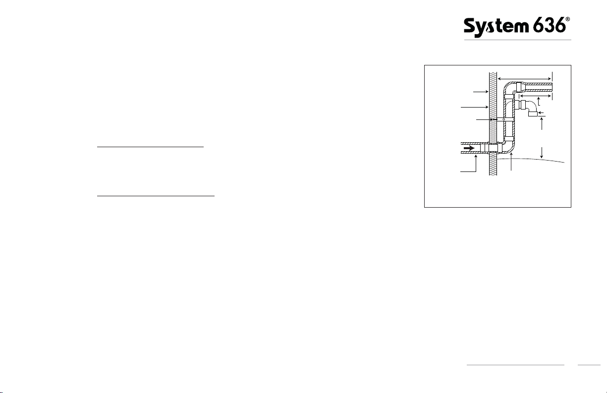
3. Termination Requirements (positive pressure venting)
yp
8" MIN.
Separation
Typical Roof Termination
3" MAX separation
Insulation in
unconditioned
space
Reducer Coupling
Approved Penetration
and Flashing as per
Building Code
Unconditioned
Attic Space
12" Above avg.
snow accumulation
Provide support for
intake and vent lines
Install condensate drain
as per appliance
manufacturer’s
recommendations
VentIntake
(a) Installation and location of terminations must be in accordance with the latest edition of
appliance manufacturer’s installation instructions, local building code requirements and
CSA B149.1 Natural Gas and Propane Installation Code.
Figure 1
Vent
Insulation in
unconditioned
space
12" MAXIMUM
Reducer coupling
3
System 636 Installation Methods
(b) Intake and vent pipes may be routed either horizontally through an outside wall
(see Figure 1) or vertically though the roof (see Figure 2).
(c) To avoid recirculation of exhaust gas on roof terminations, the end of the vent pipe must be
higher than the intake pipe. The minimum vertical separation between the end of the vent pipe
and the end of the intake pipe is 8 inches (see Figure 2).
(d) The runs of intake and vent pipes for terminations in general should be installed as close
together as possible. Specific spacing limits are 3" maximum separation for roof
Figure 2
penetrations and 6" maximum separation for wall penetrations (see Figures 1, 2 & 3).
(e) Terminate the vent piping straight up when through a chimney or fortified
penetrations (see Figure 2). For wall penetrations, the vent should be straight out or
elevated (see Figure 3).
(f) Intake piping terminating through the roof must terminate straight down through the
use of two 90° elbows (see Figure 2). On wall terminations intake piping should
point straight down through the use of one 90º elbow. (see Figure 1).
Insulation
Intake
Outside Wall
ical Wall Termination
T
Top View
6" MAX
separation
2" 90º Elbow
8" MINIMUM
Page 7
(g) A reducer may be used on the vent termination to increase the velocities of the exiting
12" MAXIMUM
Side View
Typical Wall Termination Restricted Grade
Insulation in
unconditioned space
Reducer Coupling
Provide support for
intake and vent
lines every 5 feet
Unconditioned space
Outside wall
Insulation
8" MINIMUM
12" Above expected
snow accumulation
Vent
Intake
gases away from the intake (see Figures 1 & 3). Do not direct exhaust to window wells,
alcoves or stairwells.
(h) The exit points of gas venting pipe must not be less than 3 ft. from an opening into
another building.
Figure 3
(i) Domestic Type Clothes Dryers
A moisture-exhaust duct from a domestic type clothes dryer shall not terminate within 3 ft (1m) in
any direction of any System 636 pressure regulator vent termination or fresh air intake.
Commercial Type Clothes Dryers
A dryer shall be connected to a metal moisture-exhaust duct that terminates outdoors
and shall not be less than 3 ft (1m) from any System 636 pressure regulator vent
terminations and not less than 10 ft (3m) from a fresh-air intake.
(j) The termination of the fresh air intake through the wall should be such that the bottom of the 90º elbow must be at a level of at
least 12 inches above the expected height of snow accumulation (see Figure 3).
(k) Except for: 1) appliances certified to ANSI Z21.10.3 / CSA 4.3 (Gas-fired Water Heaters,
ratings above 75,000 Btu per hour, circulating and instantaneous)
pressure steam and hot water boilers) insulating in unconditioned space is required for all vent piping. Insulation should also be considered
for inlet piping near the outside wall to prevent pipe condensation (See Figure 1). Insulation must have an R value sufficient to prevent
freezing of condensate. Consult with the insulation manufacturer for compatibility of insulation with System 636 pipe and fittings.
(Type 1):
(Type 2):
Volume III, Storage water heaters with input
and 2) appliances certified to ANSI Z21.13 / CSA 4.9 (Gas-fired low
System 636 Installation Methods
4
Page 8
(l) Follow appliance manufacturer's instructions regarding vent to appliance connections. Refer to ULC Standards Bulletin 2009-18.
(Interpretation: Clause 4.7 F, ULC - S636-08, Standard for Type BH Gas Venting Systems).
(m) For concentric vent installations see Concentric Vent Termination Kit section.
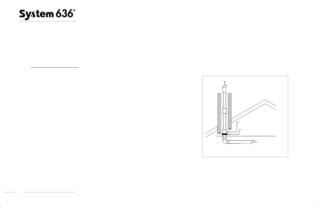
4. Chimney Installations
IPEX considers it acceptable to install System 636 piping through an existing unused
chimney space. It is suggested that installers adhere to the following guidelines when
doing such installations:
(a) Vent pipe sizing to be as per appliance manufacturers’ instructions or technical
manual.
Figure 4
To Te rmination
(b) Any existing non-certified vent piping cannot be re-used for venting and should be
(c) It is recommended that the chimney space be cleaned prior to installation to remove
(d) All recommended practices for solvent welding must be observed in the same
(e) Multiple vent pipes are permitted in one chimney space as limited by the interior available cross-sectional area. Zero clearance is
5
System 636 Installation Methods
replaced with System 636 Class IIA or IIB as required.
any debris, creosote, or other material.
manner as regular System 636 installations.
permitted between multiples runs of System 636 piping or other combustibles. (refer to Figure 4).
Coupling to sit on riser clamp to
support weight or section above
Clamp to be snugly fit but allowing
pipe travel due to expansion
From Appliance
Chimney Installations
Page 9

(f) Fresh air intakes may also be installed within existing unused chimney spaces providing acceptable spacing and clearance is obtained
at the termination as per appliance manufacturer requirements.
(g) Vertical piping through the chimney space or any other vertical spaces exceeding 20 ft (6m) is to be structurally supported by use of a
pipe coupling installed immediately above and sitting upon a snugly fit pipe clamp. One of these pipe coupling and pipe clamp
combinations is to be installed at the entrance of the chimney space to support the pipe weight. The clamp at the entrance of the
chimney is to be rigidly fixed against the wall or floor (see Figure 4). Should the pipe run exceed 60 feet (18 meters) inside the
chimney space, please contact IPEX for further guidance.
(h) It is recommended that consideration be given to obtaining an air-tight or water-tight seal as required at the chimney exit to prevent
entry of water, snow, moisture or cold air.
(i) The use of System 636 Deep Socket Couplings is recommended when available for added joint strength for chimney installations.
System 636 Installation Methods
6
Page 10

5. Support and Restraint Spacing
(a) System 636 PVC and CPVC systems must be supported horizontally at a maximum of every 5 ft (1.5 m).
(b) Supports to be used on System 636 pipe shall be suitable for use on plastic pipe and shall not be tightly clamped onto the pipe to
allow for possible expansion/contraction movement. Pipe clamps or hangers shall not have sharp edges or fulcrum points which might
damage the System 636 pipe over time.
(c) Changes in direction (e.g. 90° elbows) should be supported as close as practical to the fitting to avoid introducing excessive torsional
stresses into the system. This is especially important for vertical 90º bends. If support is being applied to the fitting, then the fitting must
be free to move during expansion and contraction of the venting system.
(d) System 636 horizontal venting shall be supported with steel strapping or equivalent. Strapping shall meet the following requirements.
• 1/2" strapping - 22 gauge steel • 3/4" strapping - 28 gauge steel
Strapping shall be fixed to supporting structure (e.g. floor joists or cross members) using typical framing nails or screws.
(e) In order to adequately support the weight of vertical vent pipe, a pipe anchor or support shall be installed at the first floor penetration
and every second floor thereafter with a System 636 coupling installed immediately above it. Securely fasten pipe anchors or supports
to the building structure. Pipe anchors or supports used for this purpose shall be suitable for use with plastic pipe. These anchors or
supports shall be snugly fastened to the vent in order to support the weight of the vent, but shall not be allowed to deform or damage
the vent. Anchors or supports supporting the weight of the vertical vent shall be in addition to the required pipe straps which are
intended only to maintain the position of the vertical vent while allowing for expansion and contraction. Make certain that allowance for
expansion and contraction is provided in all venting installations.
7
System 636 Installation Methods
Page 11

6. Expansion and Contraction
To accommodate expansion/contraction movement and stresses that may occur, IPEX suggests the following guidelines during installation:
1. Leave adequate clearance between any System 636 elbows and walls or the underside of floor boards or joists.
2. Use loose fitting clamps and hangers to allow free pipe movement if required.
3. For critical areas such as near the appliance outlet, two 45º elbows is recommended for use in lieu of one 90º elbows for more
structural flexibility.
System 636 Installation Methods
8
Page 12

TABLE 1 – PVC / CPVC Linear Expansion (ΔL) in inches
9
System 636 Installation Methods
Temp.
change
(°F) 10 20 30 40 50 10 20 30 40 50
10 0.04 0.07 0.11 0.14 0.18 0.05 0.09 0.14 0.18 0.23
20 0.07 0.14 0.22 0.29 0.36 0.09 0.18 0.27 0.36 0.46
30 0.11 0.22 0.32 0.43 0.54 0.14 0.27 0.41 0.55 0.68
40 0.14 0.29 0.43 0.58 0.72 0.18 0.36 0.55 0.73 0.91
50 0.18 0.36 0.54 0.72 0.90 0.23 0.46 0.68 0.91 1.14
60 0.22 0.43 0.65 0.86 1.08 0.27 0.55 0.82 1.09 1.37
70 0.25 0.50 0.76 1.01 1.26 0.32 0.64 0.96 1.28 1.60
80 0.29 0.58 0.86 1.15 1.44 0.37 0.73 1.09 1.46 1.82
90 0.32 0.65 0.97 1.30 1.62 0.41 0.82 1.23 1.64 2.05
100 0.36 0.72 1.08 1.44 1.80 0.46 0.91 1.37 1.82 2.28
PVC CPVC
Length of Run (ft)
Page 13

TABLE 2 – PVC / CPVC Linear Expansion (ΔL) in mm
Temp.
Change
(°C) 3 6 9 12 15 3 6 9 12 15
5 0.8 1.6 2.4 3.2 4.1 1.0 2.0 3.1 4.1 5.1
10 1.6 3.2 4.9 6.5 8.1 2.0 4.1 6.1 8.2 10.2
15 2.4 4.9 7.3 9.7 12.2 3.1 6.1 9.2 12.2 15.3
20 3.2 6.5 9.7 13.0 16.2 4.1 8.0 12.2 16.3 20.4
25 4.1 8.1 12.2 16.2 20.3 5.1 10.2 15.3 20.4 25.5
30 4.9 9.7 14.6 19.4 24.3 6.1 12.2 18.4 24.5 30.6
35 5.7 11.3 17.0 22.7 28.4 7.1 14.3 21.4 28.6 35.7
40 6.5 13.0 19.4 25.9 32.4 8.2 16.3 24.5 32.6 40.8
45 7.3 14.6 21.9 29.7 36.5 9.2 18.4 27.5 36.7 45.9
50 8.1 16.2 24.3 32.4 40.5 10.2 20.4 30.6 40.8 51.0
PVC CPVC
Length of Run (m)
System 636 Installation Methods
10
Page 14

7. Firestops
Should System 636 pass through a fire rated floor or wall, the penetration shall be firestopped with a device or system listed to
CAN/ULC-S115 for an F and/or FT Rating equivalent to the hour rating of the floor or wall.
8. Appliance Testing
Should the appliance not be equipped with an access port for flue gas testing, IPEX recommends the use of a System 636 Access Tee during
installation to allow access for flue gas testing. The Access Tee has a 1/2" female thread outlet with a removable 1/2" male thread plug.
Each time the plug is assembled into place, it shall have two wraps of PTFE (Teflon®) tape applied to the bare male threads. The Access Tee
shall be installed as close to the appliance as possible. Drilling holes in piping is NOT permitted.
9. Vent Connection to the Appliance
Please refer to the appliance installation manual for instructions to connect System 636 to the appliance exhaust and intake collar. The use of
screws to join System 636 to the appliance is NOT permitted.
10. Solvent Welding
(a) Installation of System 636 for the application of flue gas venting requires a certain degree of skill to avoid joint failures which could be
life threatening. On-site training is available from IPEX for proper solvent welding procedures as well as other important installation
points. Contact IPEX for details.
(b) Do not use solvents or cements other than what is required by this guide.
(c) For assembly of System 636 PVC piping, installers may use either System 636 PVC (gray) or CPVC (orange) cements.
11
System 636 Installation Methods
Page 15

(d) For assembly of System 636 CPVC piping, only System 636 CPVC cement may be used.
(e) Where primer is required (see Basic Principles of Solvent Welding), System 636 brand primer must be used (either purple or clear).
(f) For transitions between PVC and CPVC, only System 636 CPVC cement shall be used. In instances where transitions to ABS are
necessary, only System 636 Transition Cement shall be used. Note – some appliance manufacturers furnish adapter fittings which
are PVC but black in color. Check with the appliance manufacturer as to whether these fittings are ABS or PVC before selecting a
solvent cement.
(g) CPVC solvent cements must not be used more than 2 years beyond the date of manufacture printed on the container. PVC solvent
cements and all primers must not be used more than 3 years beyond the date of manufacture printed on the container.
Basic Principles of Solvent Welding
To make consistently good joints, the following points should be clearly understood.
1. Before the use of cement and or primer, shake the can thoroughly to ensure complete mixture of container contents.
2. Sufficient cement must be applied to fill the gap between pipe and fitting.
3. Assembly of pipe and fittings must be made while the surfaces are still wet and cement is still fluid.
4. Joint strength develops as the cement dries. In the tight part of the joint the surfaces will tend to fuse together; in the loose part,
the cement will bond to both surfaces.
Penetration and softening will be achieved by the solvent content in System 636 Cement, and additionally by using System 636 Primer
which is essentially 100% solvent. Where indicated in this manual, there are circumstances where IPEX feels that the penetration
achieved by System 636 Cement will be adequate and that the additional step of primer application may not be required.
System 636 Installation Methods
12
Page 16

Surface Interaction in Solvent Weld Joint
3/32" (2.5mm)
Approx
Chamfer
pipe ends
10-15°
Cement Coatings of Sufficient Thickness
Surfaces must be assembled
while they are wet and soft
Bonded Surfaces
Fused Surfaces
(Primer is always required for 6" and 8" piping systems and for all installations performed at temperatures of 0ºC or less.)
Note: Some jurisdictions have mandated the use of primer regardless of temperature. Verify with your local Regulatory Authority.
1. Obtain proper materials for job (proper cement and applicator for the size of piping system to be assembled).
2. Pipe must be cut as square as possible since a diagonal cut would reduce the fusing area in the most critical area of the joint.
3. A PVC wheel tube cutter or chop saw shall be used to cut the pipe. Tube cutters will produce a raised edge on the pipe end after
cutting which must be removed by a reamer. When cutting with a chop saw, a sharp and fine tooth blade must be used. Chop
saws will produce shavings which may remain inside the pipe. Failure to remove these shavings may compromise the
performance of the appliance and venting system.
4. After cutting, remove all burrs from both the inside and outside of the pipe and also chamfer the pipe end using a Reed DEB4
deburring tool. Failure to remove burrs can scrape channels into pre-softened surfaces, create hang-ups inside surface walls, or
inadvertently plow cement out of the joint during assembly.
5. Remove dirt, grease and moisture from surfaces to be welded. A thorough wipe with a clean dry rag is usually sufficient.
Moisture will increase cure times and dirt or grease can prevent adhesion.
13
System 636 Installation Methods
Page 17

6. Check pipe and fittings for dry fit before welding. For proper interference fit, the pipe must go easily into the fitting 1/3 to 2/3 of
the way. Should the dry fit be outside this range, do not proceed. Contact the System 636 supplier for further instruction.
7. Check for penetration and softening of the pipe’s surface. Take a scrap piece of System 636 pipe you will be using and make a
normal application of the cement. Then immediately, using a knife or other sharp object, try to scratch or scrape a few
thousandths of an inch of the surface away. If you are able to do so, proceed with installation. If not, try making a more
aggressive application of the cement on the scrap piece of pipe and check for penetration as noted above. If still unable to
achieve penetration or softening of the pipe surface, a primer should be used prior to solvent cement.
8. Use the right applicator for the size of pipe or fittings being joined. As a general guide, the applicator size should be equal to 1/2 the
pipe diameter. It is important that a satisfactory size applicator be used to help ensure that sufficient layers of cement are applied.
Priming (When Required)
9. The use of System 636 primer in the solvent welding process is beneficial as it allows for deeper penetration of the weld after
assembly. System 636 primer is mandatory for installation temperatures at or below 0ºC, and for all installations of 6" and 8"
System 636 pipe and fittings.
10. Using the correct applicator (as outlined in step #7), aggressively work the primer into fitting socket, keeping the surface and applicator
wet until the surface has been softened. More applications may be needed for hard surfaces and cold weather conditions. Re-dip the
applicator in primer as required. When the surface is primed, remove any puddles of primer from the socket.
11. Next, aggressively work the primer on to the end of the pipe to a point 1/2" beyond the depth of the fitting socket.
12. A second application of primer in the fitting socket is recommended.
13. Immediately and while the surfaces are still wet, apply the appropriate System 636 cement.
System 636 Installation Methods
14
Page 18

Solvent Welding
14. Stir the System 636 cement or shake can before using. Using the proper size applicator for the pipe size, aggressively work a full
even layer of cement on to the pipe end equal to the depth of the fitting socket - do not brush it out to a thin paint type layer, as
this will dry within a few seconds.
15. Aggressively work a medium layer of cement into the fitting socket; avoid puddling cement in the socket.
16. Apply a second full, even layer of cement on the pipe.
17. Without delay, while cement is still wet, assemble the pipe and fittings. Use sufficient force to ensure that the pipe bottoms in the
fitting socket. If possible, twist the pipe a 1/4 turn as it is inserted.
18. Hold the pipe and fitting together for a minimum of 15 seconds to resist buoyancy forces from disturbing the joint (push-out).
Higher potential for push-out exists with joint sizes larger than 4" and or in colder weather installations. If push-out does occur,
the joint will need to be redone.
19. A well-assembled joint should have a ring or bead of cement completely around the juncture of pipe.
20. Using a rag or dry cloth, remove all excess wet cement outside of the pipe-fitting joint.
21. Handle newly assembled joints carefully until initial set has taken place. Follow IPEX set and cure times before handling or testing
pipe system.
15
System 636 Installation Methods
Page 19

Solvent Weld Set and Cure Times (PVC or CPVC)
Set and Cure time for flue gas venting applications only.
Average Initial Set Schedule **
Temperature Range Joint Size
˚C (Celsius) ˚F (Fahrenheit) 1.5" to 2" 2.5" to 8"
15 to 40 60 - 105 5 min 30 min
5 to 15 40 - 60 10 min 2 hr
–16 to 4 3 - 40 15 min 12 hr
Note - Initial set schedule is the necessary time to allow before
the joint can be carefully handled.
In damp or humid conditions above 60% relative humidity
allow 50% more set time.
** These figures are estimates based on testing done under laboratory conditions. Field working conditions can vary significantly. This chart
should be used as a general reference only.
˚C (Celsius) ˚F (Fahrenheit) 1.5" to 2" 2.5" to 8"
15 to 40 60 - 105 30 min 1.5 hr
5 to 15 40 - 60 45 min 4 hr
–16 to 4 3 - 40 1 hr 72 hr
Note - Joint cure schedule is the necessary time before
commissioning System 636 piping for flue gas venting.
In damp or humid conditions above 60% relative humidity
allow 50% more cure time.
Average Joint Cure Schedule **
Temperature Range Joint Size
Cement Shelf Life
To determine the age of System 636 cement and primer, refer to the bottom of the container where the Date of Manufacture, Expiry Date, or
both will be displayed.
System 636 Installation Methods
16
Page 20

Required Quantities of Solvent Cement
Average Number of Joints/Qt. of IPEX System 636 Cement*
Pipe Diameter (inches) 1-1/2 2 3 4 6 8
Number of Joints 90 60 40 30 10 5
For the same number of joints where primer is used, one pint will be required for each quart of cement used.
*These figures are estimates based on our laboratory tests. Due to the many variables in the field, these figures should be used as a
general guide only.
17
System 636 Installation Methods
Page 21

Safety Precautions
All solvent cements and primers for plastic pipe are flammable and shall not be used or stored near heat, spark, open flames and other
sources of ignition. Vapors may ignite explosively. Keep containers closed when not in use and covered as much as possible when in use.
Use in well ventilated area. If confined or partially enclosed, use forced ventilation or NIOSH-approved respirator. Avoid breathing vapors.
Atmospheric levels should be maintained below established exposure limits contained in the product’s Material Safety Data Sheet. If airborne
concentrations exceed those limits, use of NIOSH-approved organic vapor cartridge with full face piece is recommended. The effectiveness of
an air purifying respirator is limited. Use it only for a single, short term exposure. For emergency and other conditions where short-term
exposure guidelines may be exceeded, use an approved positive pressure self-contained breathing apparatus. Do not smoke, eat or drink
while using these products. Avoid contact with skin, eyes and clothing. Wash clothing if contaminated before re-use. May cause eye injury.
Protective equipment such as gloves, goggles and an impervious apron shall be used. Keep out of reach of children. Carefully read our
Material Safety Data Sheets and follow all precautions.
First Aid
Inhalation: If feeling illness from inhalation, person should be moved to a source of fresh air. If not breathing, give artificial respiration. If
breathing is difficult, give oxygen. Call a physician.
Eye Contact: Flush with plenty of water for 15 minutes and call a physician.
Skin Contact: Wash skin with plenty of soap and water for at least 15 minutes. If irritation develops, get medical attention.
Ingestion: If swallowed, consume 1 to 2 glasses of water or milk, DO NOT INDUCE VOMITING. Contact physician immediately.
System 636 Installation Methods
18
Page 22

Use Caution with Welding Torches
At construction sites where System 636 is being installed or has recently been solvent welded, extreme caution should be taken when using
welding torches or other equipment where sparks may be involved. Flammable vapors from welded joints sometimes linger within or around a
piping system for some time.
Special care must be taken when using a welding torch around System 636 systems in industrial plant areas with little or no air circulation. In
all cases, solvent vapors must be removed by air circulation, purging, or other means prior to the use of welding torches, or other spark or
flame generating equipment or procedures. This includes electronic sources of ignition such as, electronic vapour cigarettes.
11. Handling and Storage of System 636 Cement and Primer
Store System 636 cement and primer in the shade between 4ºC (40ºF) and 43ºC (110ºF) or as specified on label. Keep away from heat,
spark, open flame and other sources of ignition such as, electronic vapour cigarettes. Secure container lid tightly when not in use to prevent
escape of solvent vapours. If the unopened container is subjected to freezing, it may become extremely thick or gelled. This cement can be
placed in a warm area, where after a period of time, it will return to its original, usable condition. But such is not the case when gelatin has
taken place because of actual solvent loss—for example, when the container was left open too long during use or not properly sealed after
use. Cement in this condition should not be used and should be properly discarded.
IPEX solvent cements are formulated to be used “as received” in original containers. Adding thinners or primers to change viscosity is strictly
prohibited. If the cement is found to be jelly-like and not free flowing, it should not be used.
19
System 636 Installation Methods
Page 23

12. Handling and Storage of System 636 Pipe and Fittings
(a) The PVC and CPVC materials used in System 636 piping are strong and lightweight materials. Care should be taken in handling and
storage to prevent damage to the pipe.
System 636 pipe should be given adequate support at all times. It should not be stacked in large piles, especially in warm temperature
conditions, as bottom pipe may become distorted and joining will become difficult.
For long-term storage, pipe racks should be used, providing continuous support along the length. If this is not possible, timber supports
of at least 3" bearing width, at spacings not greater than 3 ft centers, should be placed beneath the piping. If the stacks are
rectangular, twice the spacing at the sides is required. Pipe should not be stored more than seven layers high in racks. If different
classes of pipe are kept in the same rack, pipe with the thickest walls should always be at the bottom. Sharp corners on metal racks
should be avoided.
For temporary storage in the field when racks are not provided, care should be taken that the ground is level and free of sharp objects
(i.e. loose stones, etc.). Pipe should be stacked to reduce movement, but should not exceed three to four layers high.
Since the soundness of any joint depends on the condition of the pipe end, care should be taken in transit, handling and storage to
avoid damage to these ends. The impact resistance and flexibility of System 636 piping are reduced as temperatures approach 0ºC
(32ºF) and below. Care should be taken when unloading and handling pipe in cold weather. Dropping pipe from a truck or forklift may
cause damage. Methods and techniques normally used in warm weather may not be acceptable at the lower temperature range.
When loading pipe onto vehicles, care should be taken to avoid contact with any sharp corners (i.e. angle irons, nail heads, etc.),
as the pipe may be damaged.
System 636 Installation Methods
20
Page 24

While in transit, pipe should be well secured and supported over the entire length and should never project unsecured
from the back of a trailer.
b) Prolonged Outdoor Exposure
Prolonged exposure of System 636 pipe to the direct rays of the sun will not damage the pipe. However, some mild discoloration may
take place in the form of a milky film on the exposed surfaces. This change in color merely indicates that there has been a harmless
chemical transformation at the surface of the pipe. A small reduction in impact strength could occur at the discolored surfaces but they
are of a very small order and are not enough to cause problems in field installation.
(c) Protection – Covering
System 636 PVC and CPVC pipes are packaged in crates and wrapped in protective plastic film, which protects from UV and keeps the
pipe clean. Discoloration of exposed pipe can be avoided by shading it from the direct rays of the sun. This can be accomplished by
covering the stockpile or the crated pipe with a light colored opaque material such as canvas. If the pipe is covered, always allow for
the circulation of air through the pipe to avoid heat buildup in hot summer weather. Make sure that the pipe is not stored close to
sources of heat such as boilers, steam lines, engine exhaust outlets, etc.
(d) System 636 gas venting systems should not be painted. However if painted, only latex/waterbase paint shall be used and all product
markings must be either visible or accessible for visual inspection. Example, apply masking tape over product markings prior to
painting. The ability to pull-back on the masking tape will allow for future inspection.
21
System 636 Installation Methods
Page 25

13. System 636 Statement of the Bases for Acceptance
The acceptance of any appliance using IPEX System 636 PVC or CPVC Gas Venting Systems is strictly predicated on the following conditions:
Condition No. 1 Only System 636 PVC or CPVC components supplied for the job have been used in the installation, with no
unauthorized substitutions.
Condition No. 2 The system has been installed in accordance with CSA B149 Gas and Propane Installation Code.
Condition No. 3 The appliance manufacturer’s instructions have been followed .
Condition No. 4 IPEX's System 636 installation recommendations have been observed.
Condition No. 5 All installations must be done in full compliance of local Building and Fire Codes; especially with respect to Plenums
and High Buildings.
System 636 Installation Methods
22
Page 26

14. Maintenance
IPEX recommends that the System 636 gas venting system be checked once per year by a qualified System 636 service technician during any
regular maintenance activities as required for the heating appliance.
15. Training
The following is an excerpt from CSA B149.1-15 for
Natural Gas and Propane Installation Code:
4.4.2:
Personnel performing installation,
operation, and maintenance work shall be
properly trained in such functions.
IPEX recommends that installers receive formal training on
System 636 every 3 years to ensure proper installation
methods are utilized at all times.
AIR/GAS
• NEVER use compressed air or gas in PVC/CPVC
• NEVER test PVC/CPVC pipe and fittings with
Use of compressed air or gas in PVC/CPVC
pipe and fittings can result in explosive
failures and cause severe injury or death.
WARNING
pipe and fittings.
compressed air or gas, or air-over-water boosters.
23
System 636 Installation Methods
Page 27

16. Accessory Installation Instructions
Access Tee
1. The Access Tee shall be installed in such a manner as to prevent the collection of condensate,
preferably on a vertical run of pipe.
2. PVC Access Tees shall only be used on PVC venting systems. CPVC access tees shall only be used
on CPVC venting systems.
3. Solvent cement the access tee into the piping system. Allow for the proper set and cure times before
proceeding to next step.
4. Apply two full turns of Teflon
®
Tape to the threaded portion of the 1/2” plug.
5. Hand thread and hand tighten the plug into the bushing. Take care not to cross-thread the fittings.
6. Once hand tight, slowly turn the plug an additional one and a half (1.5) turns.
7. If the fittings appear to be damaged during threading then the entire assembly should be replaced. If the Teflon Tape was unraveled
during threading the plug will need to be re-installed with new tape.
8. Repeat steps 4-7 every time the plug is removed ensuring to use new Teflon Tape each time.
System 636 Installation Methods
24
Page 28

Low Profile Side Wall Termination Kit
Termination kits must be tested and certified for
use with whatever brand of heating appliance
and pipe-fitting-cement system is used. IPEX
termination kits such as the Low Profile are fully
certified for use with IPEX product only.
System 636 PVC Low Profile vent kits are made
from certified compound and are rated to 65ºC
maximum.
The vent termination must maintain all termination clearances and be installed
in accordance with local building code and CSA B149.1 Natural Gas and
Propane Installation Code. (see Figure 5)
Installation Procedure
1. Once the proper location has been determined, cut 2 holes in the wall
large enough to accommodate the pipe. Pipe diameters and distance
between hole centers can be found in Table 3.
2. Slide both the intake and vent pipes through the holes. Solvent weld both pipes to the base of the vent termination kit, following the
solvent welding procedures outlined in this guide. (see Figure 7)
TABLE 3 – Low Profile Termination Kits Dimensions
Item # Description Pipe O.D.
196984 2" Flush Mount Vent Kit 2.375" 5.6"
196985 3" Flush Mount Vent Kit 3.5" 5.6"
196986 4" Flush Mount Vent Kit 4.5" 5.6"
Hole Spacing
(ctr to ctr)
TABLE 4 – Each Kit Contains:
Qty Item Description
1 Base (two holes)
1 Cap (one hole)
8 Stainless Steel Screws
4 Plastic Anchors
25
System 636 Installation Methods
Page 29

To appliance intake
air connection
From appliance vent
pipe connection
Vent/Air
termination
Grade or snow line
12"
MIN
12"
MIN
to overhang
3. To fasten the Base to the wall, use the supplied screws and anchors. A
3/16" (5mm) diameter, 1-3/16" (30mm) deep, will need to be drilled
for the anchors. Locate the anchor hole using the base as a template.
4. Screw the Cap to the Base using the supplied screws.
5. Once the vent termination and pipes are secured, the wall
penetrations will need to be sealed from the interior using a PVC-
compatible sealant material.
Figure 6
Possibl
e Orientation
Figure 5
*
*
s
* confirm minimum clearance for
termination with local building code.
System 636 Installation Methods
26
Page 30

6. When locating the penetration of the vent and air pipes, ensure the
r
V
Figure 7
termination is properly oriented as shown in Figure 6. For multiple vent
Vent Piping
Air Piping
Vent Base
Vent Cap
terminations ensure that a minimum clearance of 12 inches be
maintained between edge of air inlet and adjacent vent outlet and that
all vent pipes and air inlets terminate at the same height to avoid
possibility of severe personal injury, death, or substantial property
damage. (see Figure 8)
7. When installing the vent termination in a vertical configuration, ensure
the vent piping is located above the air inlet piping. This will avoid the
risk of flue gas products recirculating into the air inlet and building. (see
Figure 6).
Figure 8
ent
12" MIN. between edge of ai
inlet and adjacent vent outlet
Vent/Air Termination
Air
27
System 636 Installation Methods
Page 31

Concentric Vent Termination Kit
A
B
D
D
C
E
G
1
2
3
4
5
F
System 636 Pipe, Fittings, Termination Kits and Cements are
certified as a system and must be installed as such. Different
manufacturers have different materials, joining systems and
adhesives. Do NOT mix pipe, fittings, cements, or joining
methods from different BH Vent manufacturers, this can result in
unsafe conditions and will void the certification.
System 636 PVC/CPVC concentric vent kits are made from
certified compounds. PVC kits are rated to 65ºC maximum and
CPVC kits are rated to 90ºC maximum.
All termination kits must be located and installed in accordance
with local building code and CSA B149.1 Natural Gas and
Propane Installation Code.
Figure 9
Table 5
Concentric Vent
Termination Kits Include:
AB*C=
Dimension (Inches)
Nominal Pipe
Size
FG
Material Concentric Kit Item # D E
PVC 2" x 16" 196005 29.0 16.5 3.5 2 2 7.38 1.75
CPVC 2" x 16" 197040 29.0 16.5 3.5 2 2 7.38 1.75
PVC 2" x 28" 196105 41.0 28.0 3.5 2 2 7.38 1.75
CPVC 2" x 28" 197033 41.0 28.0 3.5 2 2 7.38 1.75
PVC 2" x 40" 196125 53.0 40.0 3.5 2 2 7.38 1.75
PVC 3" x 20" 196006 36.1 20.0 4.5 3 3 8.75 2.25
CPVC 3" x 20" 197009 36.1 20.0 4.5 3 3 8.75 2.25
PVC 3" x 32" 196106 48.1 32.0 4.5 3 3 8.75 2.25
CPVC 3" x 32" 197107 48.1 32.0 4.5 3 3 8.75 2.25
PVC 3" x 44" 196116 60.1 44.0 4.5 3 3 8.75 2.25
CPVC 3" x 44" 197117 60.1 44.0 4.5 3 3 8.75 2.25
PVC 4" x 36" 196021 56.0 37.3 6.62 4 4 10.00 3.50
CPVC 4" x 36" 197021 56.0 37.3 6.62 4 4 10.00 3.50
1 Wye - (Concentric)
2 Rain Cap
4 Fresh Air Intake Pipe (Outer)
5 Stainless Steel Bolt & Nut
3 Exhaust Vent Pipe (Inner)
45º
B* Dimension be may be shortened to a minimum of 12". Inner pipe (item 3)
must remain "F" inches longer than the outer pipe (item 4). Cut pipe ends
square and solvent weld as outlined in the System 636 installation manual.
C= Installation cutout should be at least 1/2" larger than dimension “C”.
Lengthening the units is not permitted.
System 636 Installation Methods
28
Page 32

Concentric Vent Kit Assembly
1. Once the proper location has been determined, cut a hole in the roof or wall large enough to accommodate the outer pipe. The size of
the hole can vary greatly depending on the roof pitch.
2. As per the procedures outlined in the System 636 Installation Guide, solvent weld the inner pipe to the concentric wye fitting.
3. Solvent weld the outer pipe to the concentric wye fitting.
4. Slide the assembly through the roof or wall penetration. (Install flashing if needed).
5. To permanently affix the rain cap, it should be solvent welded to the inner pipe. For installations where removal of the cap may be
required for service or cleaning the cap, it can be fastened mechanically (drill location reference 5 in Figure 9). For either installation
method, the outer pipe is only a friction fit with the cap.
6. Once the rain cap is installed, and the kit secured as outlined below, the kit can be connected to the venting system.
29
System 636 Installation Methods
Page 33

Installation / Support Procedures
1. Kits must be securely fastened to structure, to ensure dimensions shown on Table 5 and
Figure 9 are maintained.
Figure 10: Wall Termination
1” Min
2” Max
(From wall
or Face Plate)
Exhaust
Clamp or Strap
(Field Supplied)
Exhaust
2. Straps are field supplied. Use straps, clamps or equivalent that will not score or damage the
pipe. Expansion and contraction should be addressed between appliance and termination point.
3. All penetrations must be sealed according to local building codes. Caulking for side wall
terminations and flashing for roof penetrations are typical. Use only PVC/CPVC compatible
sealing material, contact IPEX for a complete list.
4. The weight of the concentric kits must be supported by the clamps/straps and not by the vent
system it connects to.
Air Intake
Exterior wall
Figure 11: Roof Termination
Exhaust
Air Intake
Flashing
(Field Supplied)
Air Intake
Distance above avg.
snow fall or grade
Ref: CSA B149.1
Distance above avg.
snow fall or grade
Ref: CSA B149.1
Clamp or Strap
(Field Supplied)
Roof
5. Insulating exhaust piping in unconditioned space to prevent freezing may be required by code.
Air Intake
6. The pipe length of the concentric vent kit can be shortened; providing that the cutting and welding
Exhaust
procedures adhere to the System 636 guidelines.
7. Pipe lengths and/or fittings can be solvent welded to the socket of the rain cap in order to divert or extend the exhaust gas; providing
that the appliance manufacture confirms that the extra length or changing in direction will not adversely impact the flow of flue gas.
System 636 Installation Methods
30
Page 34

Typical Concentric Vent Kit Spacing
For multiple horizontal installations, keep Concentric Vent Kit gaps
Figure 12: Typical CVK Spacing
Sidewall Termination for Multiple Horizontal
Concentric Vent
close (up to 4" apart) or over 24" apart.
These guidelines are not appliance specific; OEM manufacturers may
supply spacing dimension specific to each appliance. In this case the
manufacturer’s recommendations shall supersede those described
herein.
4”
MAX
24” MIN
4”
MAX
To prevent flue gas from recirculating, IPEX recommends installing
multiple concentric kits as follows:
• 2 concentric vent kits: either maintain a 24" minimum distance apart, or have the rain caps no more than 4" apart
• 3 concentric vent kits:
Option 1 – keep all 3 kits at least 24" apart.
Option 2 – group 2 kits close together up to a maximum of 4" apart and the third kit over 24" apart.
• 4 or more concentric vent kits:
Option 1 – keep all concentric kits at least 24" apart.
Option 2 – group the CVK’s in pairs, having 2 kits close together to a maximum of 4" apart, keeping the next grouping of 2 kits over
24" away as per Figure 12.
The dimensions shown in Figure 12, are distances between the edges of the rain caps.
24” MIN
to next CVK
31
System 636 Installation Methods
Page 35

Mechanically Fastened Rain Cap
A
B
D
D
C
E
G
1
2
3
4
5
F
The Rain Cap must be installed with the supplied Stainless Steel bolt and lock nut, and in accordance with the following instructions and
diagram (Figure 9).
1. Locate the drill location dimple on the outside of the
rain cap. (drill location reference 5 in Figure 9)
Figure 9
2. At this location, drill through the cap and the inner pipe
wall. Ensure that the path of the hole is perpendicular to
the inner pipe NOT the outside of the cap. For the 2" &
3" kit, drill a 3/16" hole, for the 4" kit, a 1/4" hole.
45º
3. Insert the bolt and tighten the lock nut supplied with the
Concentric Vent Kit. Do not over tighten (do NOT use
field supplied screws).
System 636 Installation Methods
32
Page 36

System 636 Pipe, Fittings and Cements are certified as a system and must be installed as such.
Different manufacturers have different materials, joining systems and adhesives.
Do NOT mix pipe, fittings, solvents, or joining methods from different BH Vent manufacturers, as
this can result in unsafe conditions.
These recommendations were issued in February 2018 and supercedes manual dated November 2016. These
recommendations are subject to periodic review and updates may occur without notice.
IPEX Inc. 1425 North Service Rd. E., Unit 3, Oakville, Ontario, Canada, L6H 1A7
Website: ipexna.com
IPEX System 636 Installation Methods - Cdn Customers call IPEX Inc. 866.473.9462 - U.S. customers call IPEX USA, LLC 800.463.9572
Products manufactured by IPEX Inc. and distributed in the United States. by IPEX USA LLC. | System 636
®
is a trademark of IPEX Branding Inc.
IGMESTIP161003 © 2018 IPEX MS0035UC
 Loading...