

Page 1
Doc No: PH485Ex1-UM-001
18 May 2014
USER’S MANUAL
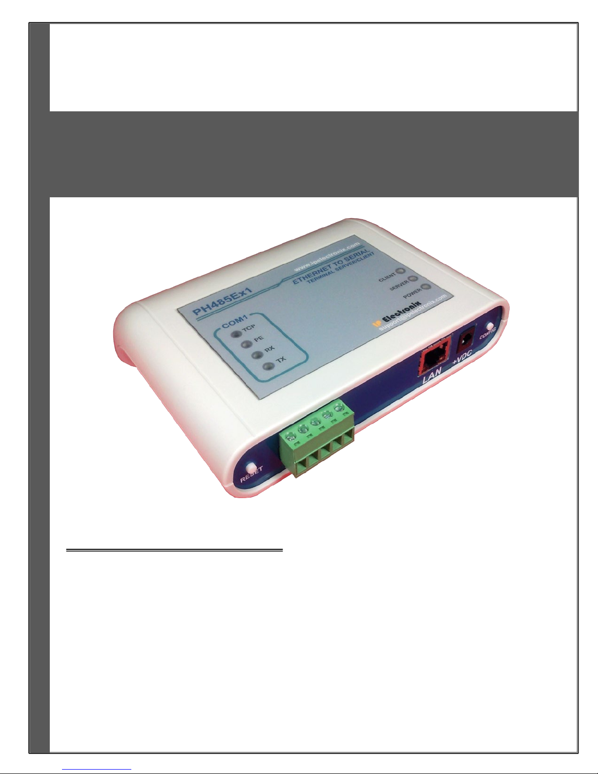
PH485Ex1
#1 RS-485 Serial Port to Ethernet, Terminal Server/Client
IPEX
(IP Electronix)
Page 2

www.ipelectronix.com
IPEX (IP Electronix) PH485Ex1
: User’s Manual
Contents
1. INTRODUCTION ....................................................................................................................................... 3
2. SPECIFICATIONS ...................................................................................................................................... 3
3. PACKAGE CHECKLIST ............................................................................................................................... 4
4. TOP PANEL .............................................................................................................................................. 4
5. FRONT PANEL .......................................................................................................................................... 5
6. RS-485 CONNECTING METHODS .............................................................................................................. 6
7. CONNECTION DIAGRAM .......................................................................................................................... 7
8. DEVICE NETWORK AND SERIAL PORT SETTINGS ...................................................................................... 9
9. NETWORK CONNECTION TESTING ......................................................................................................... 12
10. CONNECTING TO DEVICE VIA TCP SOCKET ......................................................................................... 14
11. INSTALLING THE DRIVER SOFTWARE ................................................................................................. 15
12. SET WINDOWS COM PORTS FOR PORT 1 & PORT2 ............................................................................ 17
13. GUARANTEE ...................................................................................................................................... 21
14. TECHNICAL SUPPORT ........................................................................................................................ 21
Page 2 of 21 Doc No. : PH485Ex1-UM-001
18 May 2014
Page 3

www.ipelectronix.com
IPEX (IP Electronix) PH485Ex1
: User’s Manual
1. Introduction
IPEX PH485Ex1™ bidirectional communication terminal server/client is a simple solution for connecting serial
devices to a network which results in having 1 RS-485 serial port over Ethernet network and is compatible with
RS-485 standard devices differential Data+ & Data- signals. This converter uses transparent communicate
protocol, so it is not required to understand complex Ethernet TCP/IP protocol, and no modification in serial
programs is needed. It operates as a Real COM, TCP Server or TCP Client Full-Duplex converter and supports
bidirectional connection.
PH485Ex1™ is designed for industrial usage and is useful for connecting any device with a serial interface to a
computer via Ethernet supported network like LAN, WAN … and can be used in Industrial Automation,
Telecommunications, SCADA Systems, and DCS Systems ….
Protection against Surge, ESD and EMI is implemented in its design and it has 3kV isolation between Ethernet
and RS-485 sides.
PH485Ex1™ comes complete with drivers for Microsoft Windows XP/CE/2003/2008/7. Its setup file creates a
virtual COM Port on your Server, PC or Laptop with configurable baud rate, 8 bits data length and 1 stop bit
fixed setting.
2. Specifications
Number of Ports: #1 RS-485 Serial Port, #1 Ethernet RJ45 (10/100 Mbps) Port
Serial Standard: EIA RS-485, Standard, Asynchronous Half-Duplex 2-Wire
RS-485 Signals: Data+, Data-, GND
RS-485 Baud Rates: 300, 600, 1200, 2400, 4800, 9600, 19200 and 38400 bps; Selectable
RS-485 Parity: Even, Odd, None, Mark and Space; Selectable
Supports Point-to-Point and Multidrop Configuration
Transmission Medium: Twisted Pair Cable or Shielded Wire
Maximum Communication Distance: 1200m (4000 feet)
Loading: Supported up to 32 Nodes
Network Protocols: ICMP, IP, TCP, UDP, DHCP, Telnet, DNS, SNMP, HTTP, SMTP, ARP
Windows Virtual COM Drivers: Windows 95/98/ME/NT/2000, Windows XP/2003/Vista/2008/7 x86/x64,
Power (Green) LED Indicator
Transmit (Blue) and Receive (Yellow) LED Indicator for All Ports
ESD Protection: RS-485 Bus-Pin ESD Protection Exceeds ±15 kV Using Human-Body Model (HBM)
Dimensions: 36.41mm x 121.82mm x 140 mm (1.43inch x 4.79inch x 5.51inch)
Operating Temperature: -10°C to +70°C (+14°F to +158°F)
1 Year Guarantee and 5 Years Support
Page 3 of 21 Doc No. : PH485Ex1-UM-001
18 May 2014
Page 4
www.ipelectronix.com
IPEX (IP Electronix) PH485Ex1
: User’s Manual
3. Package Checklist
Before installing the PH485Ex1, verify that the package contains the following items:
1) PH485Ex1 2) Adaptor Jack
3) Installation CD-ROM 4) Guarantee Card
NOTE: Notify your sales representative if any of the above items is missing or damaged.
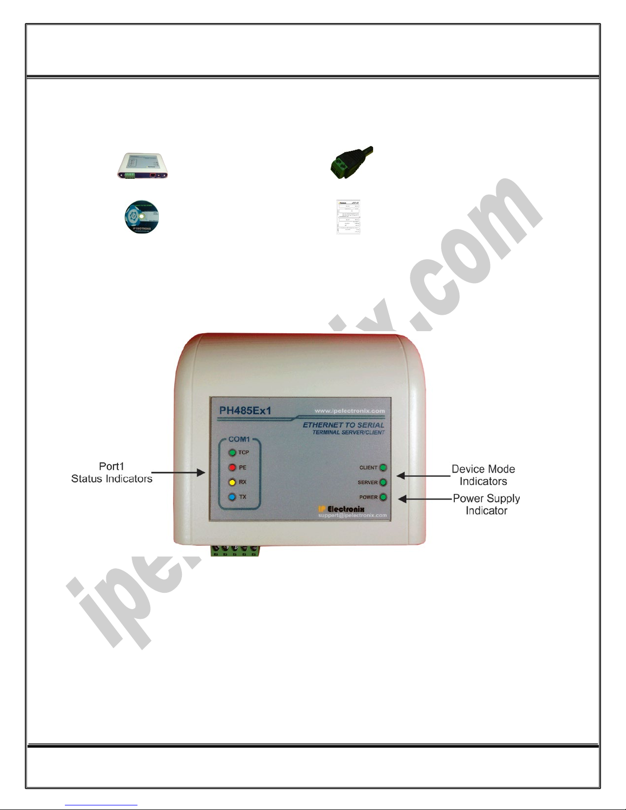
4. 0B0BTop Panel
General Indicators:
POWER LED (Green): It is turned ON, when the power supply connects to +VDC and GND correctly.
SERVER LED (Green): It is turned ON if the device is in Server Mode.
CLIENT LED (Green): It is turned ON if the device is in Client Mode.
Port Indicators:
TCP LED (Green): It is turned ON if a TCP connection between the device and a remote Server/Client established.
PE LED (Red): It is blinking if the device detecting a Parity Error in data.
RX LED (Yellow): It is blinking when the device receive data on serial port.
TX LED (Green): It is blinking when data is transmitting from the device serial port.
Page 4 of 21 Doc No. : PH485Ex1-UM-001
18 May 2014
Page 5
www.ipelectronix.com
IPEX (IP Electronix) PH485Ex1
: User’s Manual
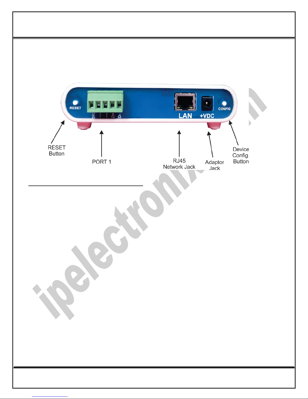
5. Front Panel
Device Power Supply +VDC (IMPORTANT!)
To working properly, you should connect a DC Power Supply to PH485Ex1. The voltage of the Power Supply
should be from +10V to +30V. For example, this device is working with a single +12V, +15V or +24V DC Adaptor.
Page 5 of 21 Doc No. : PH485Ex1-UM-001
18 May 2014
Page 6
www.ipelectronix.com
IPEX (IP Electronix) PH485Ex1
: User’s Manual
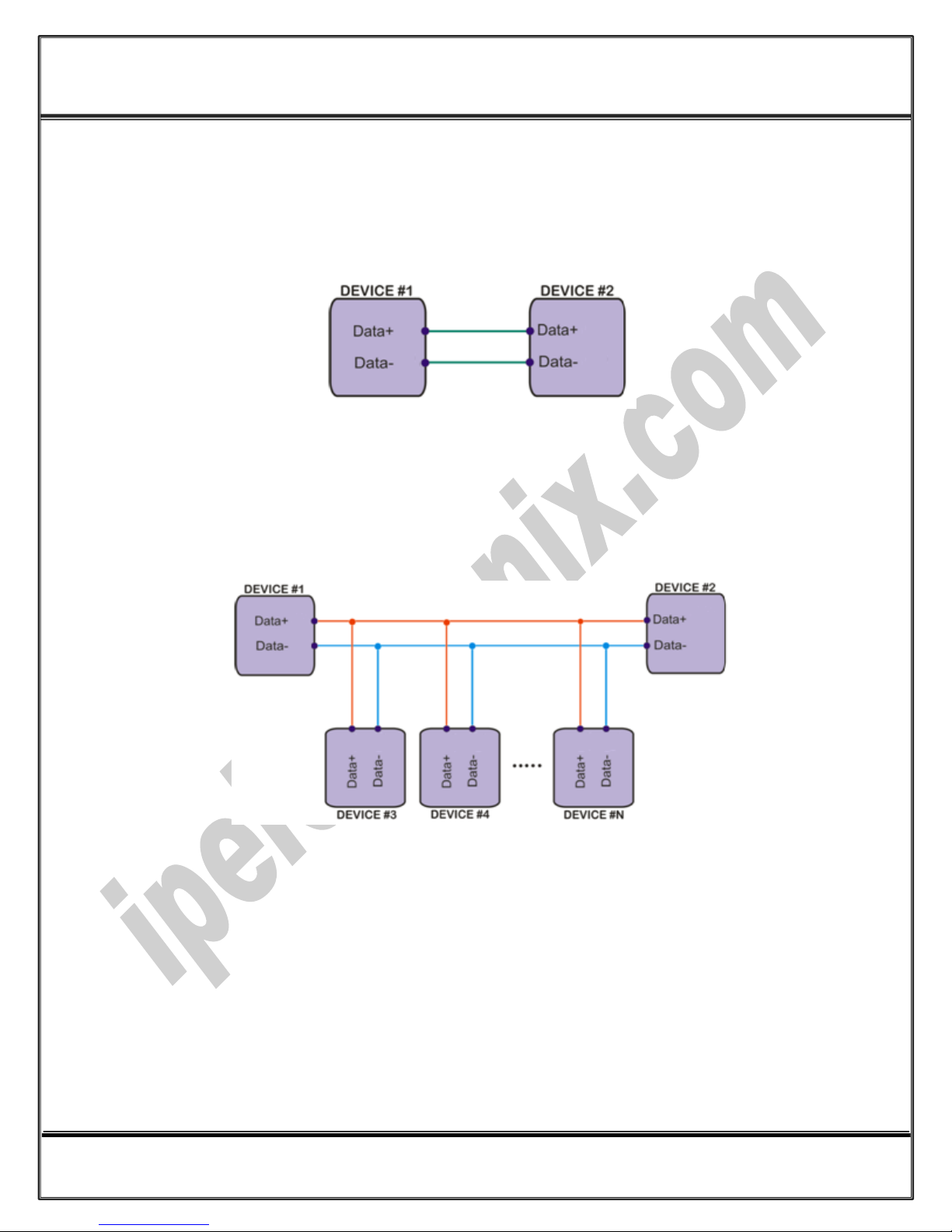
6. RS-485 Connecting Methods
6.1 RS-485: Point to Point Connection
6.2 RS-485: Multipoint Network
Page 6 of 21 Doc No. : PH485Ex1-UM-001
18 May 2014
Page 7
www.ipelectronix.com
IPEX (IP Electronix) PH485Ex1
: User’s Manual
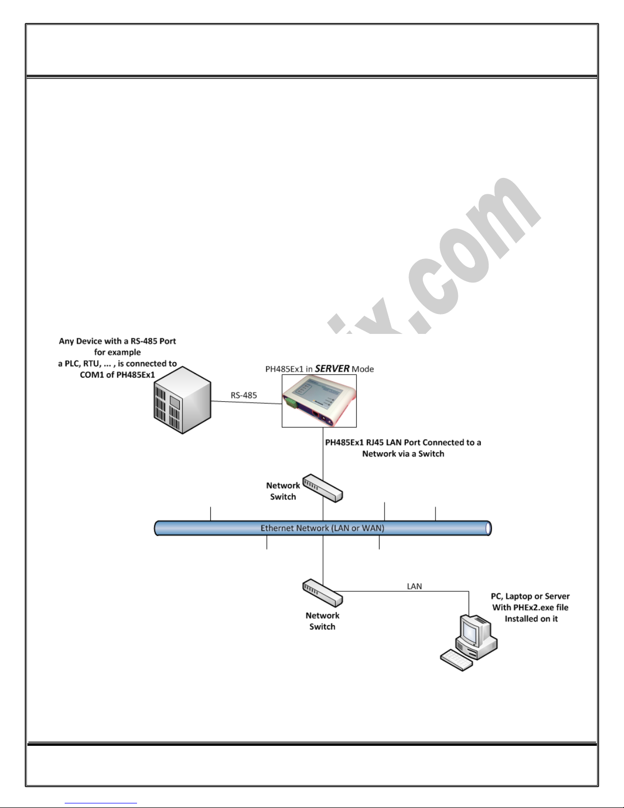
7. Connection Diagram
7.1 PH485Ex1 as a Terminal Server
The below diagram is a typical connection configuration of PH485Ex1. You can connect one device with a RS-485
serial port to COM1 RS-485 serial port of the PH485Ex1. Then you can connect to the device, behind the
network by any application software you want.
There are two methods in order to be connected to the PH485Ex1 COM Port via Ethernet. As the first way, it is
possible to connect to the device by opening a normal COM Port (if you have installed PHEx2.exe software on
the PC or Laptop). The second way is connecting to PH485Ex1 by opening a TCP Socket without need of any
auxiliary driver.
To configure network settings of PH485Ex1 such as IP Address or Subnet mask, connect a computer with a
terminal emulator software (like Hyper Terminal) on it, to the COM1 of PH485Ex1 and restart PH485Ex1 by
pressing the Network Config. Button.
Page 7 of 21 Doc No. : PH485Ex1-UM-001
18 May 2014
Page 8

www.ipelectronix.com
IPEX (IP Electronix) PH485Ex1
: User’s Manual
7.2 Client/Server, Peer to Peer Connection
If you want to connect two devices which have only RS-485 Ports to each other via Ethernet network, you can
use this connecting method. Take two PH485Ex1. Set one PH485Ex1 as Server and another one as Client with
adding Remote Server IP on it. These two converters are connecting automatically via network to each other, so
COM1 of Server connects to COM1 of Client via network. Now you can connect your RS-485 devices to COM
Ports as shown in the following diagram.
Page 8 of 21 Doc No. : PH485Ex1-UM-001
18 May 2014
Page 9

www.ipelectronix.com
IPEX (IP Electronix) PH485Ex1
: User’s Manual
8. Device Network and Serial Port Settings
As shown in the connection diagram, you can connect a PC or laptop with a RS-485 serial COM port directly to
the Port 1 of PH485Ex1.
Now run a terminal emulator on your computer. You can find some terminal emulators in the Utility folder in
the installation CD. For example, we use Microsoft Hyper Terminal. Run Hyperterm.exe and then from the
properties toolbar, set the serial settings to the 19200, 8, n, 1 like this:
Remember to set Flow Control to None. Now in the Properties dialog box, select settings tab and click on the
ASCII Setup. Select the “Echo typed characters locally” and press OK.
Page 9 of 21 Doc No. : PH485Ex1-UM-001
18 May 2014
Page 10

www.ipelectronix.com
IPEX (IP Electronix) PH485Ex1
: User’s Manual
Turn on the PH485Ex1 by connecting a DC Power Supply to it. The voltage of the Power Supply should be from
+10V to +30V. For example, this device is working with a single +12V, +15V or +24V DC Adaptor. If all the
connections are OK, you should see the default settings on the Hyper Terminal.
Entering Device Network and Serial Ports Setting Menu (IMPORTANT!)
Now to enter device network and serial ports settings menu, follow the below procedure step by step:
1- Push the CONFIG button on the right side of the front panel (Do not release it).
2- Press (and release) RESET button on the left side of the front panel.
3- Release the CONFIG button.
You should be able to see the network settings menu like this picture:
Page 10 of 21 Doc No. : PH485Ex1-UM-001
18 May 2014
Page 11

www.ipelectronix.com
IPEX (IP Electronix) PH485Ex1
: User’s Manual
You can see network default settings in this page. It is possible to change the entire network and serial ports
settings from this menu, For example, if you want to change the IP Address of the device, first press “1”, enter
new IP Address and then press “Enter”. At last press “S” to save changes and quit. The device will be restarted
automatically and booted with new settings.
Page 11 of 21 Doc No. : PH485Ex1-UM-001
18 May 2014
Page 12

www.ipelectronix.com
IPEX (IP Electronix) PH485Ex1
: User’s Manual
9. Network Connection Testing
Connect PH485Ex1 to the Ethernet based network by connecting RJ45 LAN socket to network via a switch or
Hub by an ordinary CAT5 or CAT6 cable. If everything is set properly, the green and yellow LEDs on the
PH485Ex1’s RJ45 socket will blink.
Now it is important to check the network wiring topology, and testing all the cables, routers, switches … in the
route from PH485Ex1 to the computer. This test is done simply by using PING command from computer.
Go to Windows command prompt, (press WINDOWS KEY + R to going to run dialog and then type CMD and
press enter):
Type ping with the device IP address, for example “ping 192.168.0.2”and press Enter.
Now you should see the ping response from the device.
Page 12 of 21 Doc No. : PH485Ex1-UM-001
18 May 2014
Page 13

www.ipelectronix.com
IPEX (IP Electronix) PH485Ex1
: User’s Manual
If there are any problems in the network, you could not see response from the device:
If you see this timeout window, you can’t continue installation and first you should solve network problem by
consulting your network administrator.
Page 13 of 21 Doc No. : PH485Ex1-UM-001
18 May 2014
Page 14

www.ipelectronix.com
IPEX (IP Electronix) PH485Ex1
: User’s Manual
10. Connecting to Device via TCP Socket
It is possible to directly connect to PH485Ex1 RS-485 Serial Port from any node of the network by using socket
programming. This is simply done if you know only PH485Ex1 IP Address and socket port number for each Port.
The port numbers is as follow:
- Port 1 : 9761
- Port 2 : 9762 (Only for PH485Ex2 Model)
For example we connect to Port 1 by means of Hyper Terminal. Run Hyperterm.exe and from properties dialog
box, select “TCP/IP (Winsock)”:
Enter device IP Address in the “Host address:” section, for example 192.168.0.2 and the port number in the
“Port Number:” section (port number for Port 1 is 9761 and for Port 2 is 9762), then click on OK.
Now if you type some characters, you can see that port 1 TX Blue LED is blinking that means the data is sent to
PH485Ex1 port 1.
NOTICE: Don’t forget to set PH485Ex1 in SERVER Mode for this method of connection.
Page 14 of 21 Doc No. : PH485Ex1-UM-001
18 May 2014
Page 15

www.ipelectronix.com
IPEX (IP Electronix) PH485Ex1
: User’s Manual
11. Installing the Driver Software
The second method for connecting to PH485Ex1 serial port is to install virtual COM port driver on your
computer and open ports as a normal Windows COM port.
Run PHEx2_32bit.exe if your Windows is 32 bit or PHEx2_64bit.exe if it is 64 bit from the installation CD.
NOTICE: In the Windows 64 bit systems, run apply.bat and restart your computer before setup.
Page 15 of 21 Doc No. : PH485Ex1-UM-001
18 May 2014
Page 16

www.ipelectronix.com
IPEX (IP Electronix) PH485Ex1
: User’s Manual
In this dialog box, click on Next:
Now click on Install:
Page 16 of 21 Doc No. : PH485Ex1-UM-001
18 May 2014
Page 17

www.ipelectronix.com
IPEX (IP Electronix) PH485Ex1
: User’s Manual
Now click on Finish.
12. Set Windows COM Ports for PORT 1 & PORT2
After installation is finished, stop any running application on your system and then from Windows
Start/Programs/IPEX/ run PHEX2.exe:
Simply Enter PH485Ex1 IP Address and serial port number for Port 1 and Port 2 and then press apply. For
example type 4 for Port 1 and 5 for Port 2, after applying is finished, restart your computer and then you can use
Port 1 as COM4 and Port 2 as COM5 like an ordinary Windows COM port by your application software.
Page 17 of 21 Doc No. : PH485Ex1-UM-001
18 May 2014
Page 18

www.ipelectronix.com
IPEX (IP Electronix) PH485Ex1
: User’s Manual
If during installation you see this Window:
Select “Install the software automatically (Recommended)” and click on Next.
Now click on Finish. Repeat these as long as the system asks you.
Page 18 of 21 Doc No. : PH485Ex1-UM-001
18 May 2014
Page 19

www.ipelectronix.com
IPEX (IP Electronix) PH485Ex1
: User’s Manual
IMPORTANT NOTICE: If COM Port number you select is previously used by other application, you cannot choose
that port number for the device. To see which COM Port is in use by the system, run Device Manager and from
Ports (COM & LPT) section, double click on one of the communication ports:
Now from “Port Settings” tab page, click on “Advanced…” button.
Page 19 of 21 Doc No. : PH485Ex1-UM-001
18 May 2014
Page 20

www.ipelectronix.com
IPEX (IP Electronix) PH485Ex1
: User’s Manual
Now you can see which COM port is free and which COM port is in use. You must select COM port number for
your device which is free.
Page 20 of 21 Doc No. : PH485Ex1-UM-001
18 May 2014
Page 21

www.ipelectronix.com
IPEX (IP Electronix) PH485Ex1
: User’s Manual
13. Guarantee
All products manufactured by IPEX are under warranty regarding defective materials for a period of one year
from the date of delivery to the original purchaser.
14. Technical Support
If you have any technical question or need any technical support, please contact us using this Email address:
support@ipelectronix.com
.
Page 21 of 21 Doc No. : PH485Ex1-UM-001
18 May 2014
 Loading...