

IPEX MUNICIPAL SYSTEMS Installation Manual
PVCO CIOD PRESSURE PIPE
4" (100mm) to 12" (300mm)
PVC CIOD PRESSURE PIPE & FITTINGS
4" (100mm) to 48" (1200mm)
PVC IPS PRESSURE PIPE & FITTINGS
1-1/2" (40mm) to 24" (600mm)
PVC PIPING SYSTEMS FOR HDD & OTHER TRENCHLESS APPLICATIONS
4" (100mm) to 12" (300mm)
MUNICIPAL SYSTEMS
We build tough products for tough environments
®
Installation Guide

PVC Pressure Pipe & Ftgs Installation Guide
TABLE OF CONTENTS
Introduction . . . . . . . . . . . . . . . . . . . . . . . . . . . . . . . . . . . . . .3
Pressure Pipe & Fittings Meet These Standards . . . . . . . .4
Receiving & Handling Pipe Shipments . . . . . . . . . . . . . . . .5
Before Accepting the Shipment . . . . . . . . . . . . . . . . . . . . .5
Handling the Pipe and Fittings . . . . . . . . . . . . . . . . . . . . .5
Storage at the Job Site . . . . . . . . . . . . . . . . . . . . . . . . . . .6
Cold Weather . . . . . . . . . . . . . . . . . . . . . . . . . . . . . . . . . .7
Stockpiling . . . . . . . . . . . . . . . . . . . . . . . . . . . . . . . . . . .7
Outdoor Storage . . . . . . . . . . . . . . . . . . . . . . . . . . . . . . . .7
Trench Preparation . . . . . . . . . . . . . . . . . . . . . . . . . . . . . . . .8
Safety . . . . . . . . . . . . . . . . . . . . . . . . . . . . . . . . . . . . . . .8
Excavating and Preparing the Trench . . . . . . . . . . . . . . . . .8
Depth of Trench . . . . . . . . . . . . . . . . . . . . . . . . . . . . . . . .9
Flotation . . . . . . . . . . . . . . . . . . . . . . . . . . . . . . . . . . . . .9
The Bottom of the Trench . . . . . . . . . . . . . . . . . . . . . . . . .9
Lowering Pipe & Fittings into the Trench . . . . . . . . . . . . .10
Assembling IPEX Joints . . . . . . . . . . . . . . . . . . . . . . . . . . .11
Preparation . . . . . . . . . . . . . . . . . . . . . . . . . . . . . . . . . .11
Lubrication . . . . . . . . . . . . . . . . . . . . . . . . . . . . . . . . . .12
Assembly . . . . . . . . . . . . . . . . . . . . . . . . . . . . . . . . . . . .12
For Sizes over 36 inches (900mm) . . . . . . . . . . . . . . . . .13
Curvature of the Pipeline . . . . . . . . . . . . . . . . . . . . . . . . . .14
Using PVC Fittings . . . . . . . . . . . . . . . . . . . . . . . . . . . . .14
Deflecting the Joint . . . . . . . . . . . . . . . . . . . . . . . . . . . .15
Bending the Pipe Barrel . . . . . . . . . . . . . . . . . . . . . . . . .16
Assembling to Iron Appurtenances . . . . . . . . . . . . . . . . . .17
Assembling to Cast Iron Fittings . . . . . . . . . . . . . . . . . . .17
Assembling to Butterfly Valves . . . . . . . . . . . . . . . . . . . . .17
Cutting and Chamfering the Pipe . . . . . . . . . . . . . . . . . . .18
Cutting . . . . . . . . . . . . . . . . . . . . . . . . . . . . . . . . . . . . .18
Chamfering . . . . . . . . . . . . . . . . . . . . . . . . . . . . . . . . . .18
Dimensions . . . . . . . . . . . . . . . . . . . . . . . . . . . . . . . . . . . .19
Blue Brute®/IPEX Centurion® . . . . . . . . . . . . . . . . . . . . . .20
Cycle Tough
®
Series . . . . . . . . . . . . . . . . . . . . . . . . . . . .20
Bionax PVCO . . . . . . . . . . . . . . . . . . . . . . . . . . . . . . . . .22
Outside Diameter Considerations . . . . . . . . . . . . . . . . . . .22
Blue Brute and Centurion PVC Pipe: CIOD . . . . . . . . . . . .22
Cycle Tough PVC Pipe: IPS OD . . . . . . . . . . . . . . . . . . . .23
Bionax PVCO Pipe: CIOD . . . . . . . . . . . . . . . . . . . . . . . .23
CIOD Injection-Molded PVC Fittings . . . . . . . . . . . . . . . . .24
Dimensional Data . . . . . . . . . . . . . . . . . . . . . . . . . . . . . .25
1
PVC Pressure Pipe & Ftgs Installation Guide
RECOMMENDED PRACTICES FOR
THE INSTALLATION OF IPEX
PVC PRESSURE PIPE & FITTINGS
Introduction
This booklet will answer the needs of pipe installers looking for
general recommendations on how to lay IPEX gasketed PVC
pressure pipes and fittings. Out-of-the-ordinary conditions not
covered here should be referred to the Engineer or field
inspectors to provide on-site solutions. In such cases IPEX's
advice is always available. Our objective is to encourage the
use of methods that lead to a professional installation that will
ensure the maximum service life for the pipe.
The Engineer who designs the pipeline will determine how it is
to be installed. It is not our intention that the Guide should
assume that responsibility unless the Engineer so directs.
This booklet sets out the preferred methods of installation
based on IPEX's experience and on a number of published
reports from other industry sources. Users will find additional
helpful advice in "Recommended Practice for the Installation
of PVC Pressure Pipe", AWWA C605, published by the
American Water Works
Association.
Readers are invited to order a
copy of the "Uni-Bell Handbook
of PVC Pipe - Design and
Construction". This comprehensive
reference manual covers all
aspects of design and installation
for PVC pipe & fittings. Call UniBell at (972) 243-3902 to order.
3
PVC Pressure Pipe & Ftgs Installation Guide
IPS Injection-Molded PVC Fittings . . . . . . . . . . . . . . . . . .31
Engineered Joint . . . . . . . . . . . . . . . . . . . . . . . . . . . . . .32
Dimensional Data . . . . . . . . . . . . . . . . . . . . . . . . . . . . . .33
Fabricated PVC Pressure Fittings . . . . . . . . . . . . . . . . . . .38
TerraBrute
®
CR Trenchless Applications . . . . . . . . . . . . . .39
Dimensions . . . . . . . . . . . . . . . . . . . . . . . . . . . . . . . . . .39
Minimum Bending Radius . . . . . . . . . . . . . . . . . . . . . . . .40
Joint Deflection Radius . . . . . . . . . . . . . . . . . . . . . . . . . .40
Maximum Allowable Pull Forces . . . . . . . . . . . . . . . . . . .40
Joint Assembly Instructions . . . . . . . . . . . . . . . . . . . . . . .39
General Recommendations . . . . . . . . . . . . . . . . . . . . . . .41
Resisting Thrust at Fittings & Valves . . . . . . . . . . . . . . . . .45
Bearing Strength of Undisturbed Soils . . . . . . . . . . . . . . .46
Resisting Thrust in Very Poor Soils . . . . . . . . . . . . . . . . .46
Resisting Vertical Thrust . . . . . . . . . . . . . . . . . . . . . . . . .48
Holding Pipe to Steep Slopes . . . . . . . . . . . . . . . . . . . . .49
Mechanical Thrust Restraints . . . . . . . . . . . . . . . . . . . . .49
Flanged Joints . . . . . . . . . . . . . . . . . . . . . . . . . . . . . . . .50
Tapping and Service Connections . . . . . . . . . . . . . . . . . . .50
Direct Tapping . . . . . . . . . . . . . . . . . . . . . . . . . . . . . . . .50
Service Saddles . . . . . . . . . . . . . . . . . . . . . . . . . . . . . . .50
Tapping Sleeve and Valve . . . . . . . . . . . . . . . . . . . . . . . .51
Tapped Couplings . . . . . . . . . . . . . . . . . . . . . . . . . . . . . .52
The Two Backfills and Haunching . . . . . . . . . . . . . . . . . . .53
Initial Backfill . . . . . . . . . . . . . . . . . . . . . . . . . . . . . . . .53
Final Backfill . . . . . . . . . . . . . . . . . . . . . . . . . . . . . . . . .53
Compacting the Backfill . . . . . . . . . . . . . . . . . . . . . . . . .54
Shallow Bury Considerations . . . . . . . . . . . . . . . . . . . . . .55
Percent Deflections Charts . . . . . . . . . . . . . . . . . . . . . . .56
Testing . . . . . . . . . . . . . . . . . . . . . . . . . . . . . . . . . . . . . . . . .64
Checklist . . . . . . . . . . . . . . . . . . . . . . . . . . . . . . . . . . . .64
Filling the Line . . . . . . . . . . . . . . . . . . . . . . . . . . . . . . .64
How Much Water is Needed . . . . . . . . . . . . . . . . . . . . . .65
Pressure and Leakage Tests . . . . . . . . . . . . . . . . . . . . . . .65
Repairs . . . . . . . . . . . . . . . . . . . . . . . . . . . . . . . . . . . . . . . .69
Installing the Pipe Through Casings . . . . . . . . . . . . . . . . .70
Precautions . . . . . . . . . . . . . . . . . . . . . . . . . . . . . . . . . .70
Casing Size . . . . . . . . . . . . . . . . . . . . . . . . . . . . . . . . . .70
Skids . . . . . . . . . . . . . . . . . . . . . . . . . . . . . . . . . . . . . .71
Mechanical Casing Spacers . . . . . . . . . . . . . . . . . . . . . . .71
Casing Spacer Installation . . . . . . . . . . . . . . . . . . . . . . . .72
Sealing the Casing . . . . . . . . . . . . . . . . . . . . . . . . . . . . .72
Lubricant Usage . . . . . . . . . . . . . . . . . . . . . . . . . . . . . . . . .74
Notes . . . . . . . . . . . . . . . . . . . . . . . . . . . . . . . . . . . . . . . . . .75
2

PVC Pressure Pipe & Ftgs Installation Guide
RECEIVING AND HANDLING
PIPE SHIPMENTS
Before Accepting the Shipment
IPEX pipe and fittings are manufactured to a number of
standards, none of which are more demanding than IPEX's
own Standard Product Specifications. Quality Control
inspection of the products before they leave our plants ensures
that only the highest quality products are shipped. Damage to
the pipe, or shortages, are possible and must be checked
before the shipment is signed for by the contractor.
1. Walk around the vehicle to make sure there has been no
shifting of the load during transport. If there is some
indication of shifting in transit, the contractor should
inspect each piece as it is unloaded.
2. Check the quantity shipped against the tally sheet.
The contractor must note any shortages on the trucker's
bill of lading.
3. Carefully note any sign of damage to the pipe in the form
of cracks, chips or other damage. Damage depth is
considered significant if it is more than 10% of the
thickness of the pipe wall.
4. DO NOT THROW AWAY ANY DAMAGED MATERIAL.
Mark it carefully for further inspection by the carrier or
his representative.
5. Re-order any material that is needed to make up for
missing or damaged items.
6. Notify the carrier immediately and enter a claim for
damaged or missing parts in accordance with their
instructions.
Handling the Pipe and Fittings
Pipe arrives at the job site in standard pallet size units. The
preferred method of unloading is to keep the pipe in the units
as shipped and use mechanical equipment such as fork lifts,
cherry pickers or front end loaders with forks. Do not slide the
equipment forks against the underside of pipe in a pallet. This
may damage the pipe by abrasion.
When the pipe is unloaded in full units they should be stored
on level ground and they should not be stacked more than
2 units high. The units should be supported by dunnage in the
5
PVC Pressure Pipe & Ftgs Installation Guide
Pressure Pipe and Fittings Meet These Standards
Canadian Standards Association
B137.2 “Polyvinylchloride (PVC) injection-molded gasketed
fittings for pressure applications”
B137.3 “Rigid polyvinylchloride (PVC) pipe and fittings for
pressure applications”
B137.3.1 “Molecularly oriented polyvinylchloride (PVCO) pipe
for pressure applications”
ASTM
D2241 “Poly (Vinyl Chloride) (PVC) Pressure-Rated Pipe
(SDR Series)”
F1483 “Oriented Polyvinyl Chloride, PVCO, Pressure Pipe”
American Water Works Association
AWWA C900 “Polyvinyl Chloride (PVC) Pressure Pipe
and Fabricated Fittings, 4" through 12", for
Water Transmission and Distribution”
AWWA C905 “Polyvinyl Chloride (PVC) Pressure Pipe and
Fabricated Fittings, 14" through 48"”
AWWA C907 “Polyvinyl Chloride (PVC) Pressure Fittings for
Water – 4" through 12" (100 mm through 300 mm)”
AWWA C909 “Molecularly Oriented Polyvinyl Chloride (PVCO)
Pressure Pipe, 4" through 24" (100 mm through 600 mm) for
Potable Water, Wastewater, and Reclaimed Water Service”
BNQ
NQ 3624-250 “Unplasticized Poly(Vinyl Chloride) [PVC-U]
Pipe and Fittings - Rigid Pipe for Pressurized Water Supply
and Distribution - Characteristics and Test Methods”
4

PVC Pressure Pipe & Ftgs Installation Guide
In Very Cold Weather
Although PVC pipe has very good impact resistance, it
becomes stiffer and offers reduced impact resistance at very
low temperatures. Recommended handling as described above
is all that is required under these conditions. Do not allow the
pipe to fall off the truck or into the trench. Individual lengths
of pipe should not impact on each other as they are unloaded
or stockpiled.
Stockpiling
Where it is necessary to remove pipe from their crates for
storage, individual lengths should be placed on level ground
and secured to prevent them from rolling.
Prolonged Outdoor Storage
Prolonged exposure of PVC pipe to the direct rays of the sun
has no practical effects on the performance of the pipe.
However some discoloration may take place in the form of a
milky film on the exposed surfaces. This change in color
merely indicates that there has been a chemical transformation
at the surface of the pipe. A small reduction in impact
strength could occur at the discolored surfaces. Other strength
properties such as pressure capacity and structural strength
are completely unaffected by this discoloration.
Discoloration of the pipe can be avoided by shading it from
the direct rays of the sun. This can be accomplished by
covering the stockpile or the crated pipe with an opaque
material such as canvas. If the pipe is covered, always allow
for the circulation of air through the pipe to avoid heat buildup
in hot summer weather. Make sure that the pipe is not stored
close to sources of heat such as boilers, steam lines, engine
exhaust outlets, etc.
7
PVC Pressure Pipe & Ftgs Installation Guide
same way they were protected while on the transport. The
weight of the unit should be borne by the dunnage rather than
the pipe.
Units of pipe should not be lifted with single cables or chains.
The wooden frames around the units should not be used as
lifting points. Use straps and spreaders about 12 feet (3.7m)
apart looped under the load.
Should mechanical equipment not be available, caution should
be exercised when the pipe is unloaded by hand. Each unit or
crate of pipe will be approximately 4 feet (1.2m) wide and will
vary in height depending on the size of pipe in the unit. Where
several tiers of pipe are in the unit they will be held in place
with steel straps. By undoing the outer strap the top tier of
pipe may be unloaded by individual lengths. The length
behind the one being unloaded should be held in place with
wooden chocks. Lighter pipes may be carefully handed down
from the top of the load, but heavier pipes will require the use
of ropes and skids. As each tier is unloaded, the interlacing
straps are broken to provide access to the lower tier.
Storage at the Job Site
The preferred method of storage at the job site is in units or
crates as shipped.
When the pipe is strung along the trench, place it as close as
possible to the line of the trench, to the side opposite the area
reserved for the storage of spoil. Locate the pipes where they
can be lowered into the trench with the least amount of
additional handling.
6
PVC Pressure Pipe & Ftgs Installation Guide
Depth of Trench
For water distribution and transmission lines, pipe should be
buried so that the top of the pipe is at least 6" (150mm)
below the deepest recorded penetration of frost. Where surface
loads will be encountered and where frost is not a problem,
the minimum height of cover over the crown of the pipe is 12"
(300mm). Before vehicles pass over the line of the pipe under
shallow cover, make sure embedment material has been
completed and compacted to at least 95% standard proctor
density and has a minimum modulus of soil reaction (E’) of
1000psi.
Flotation
Where it is not possible to remove standing water from the
trench and the pipe will be in a flooded condition, it should be
held at grade with a soil cover of at least twice the pipe
diameter.
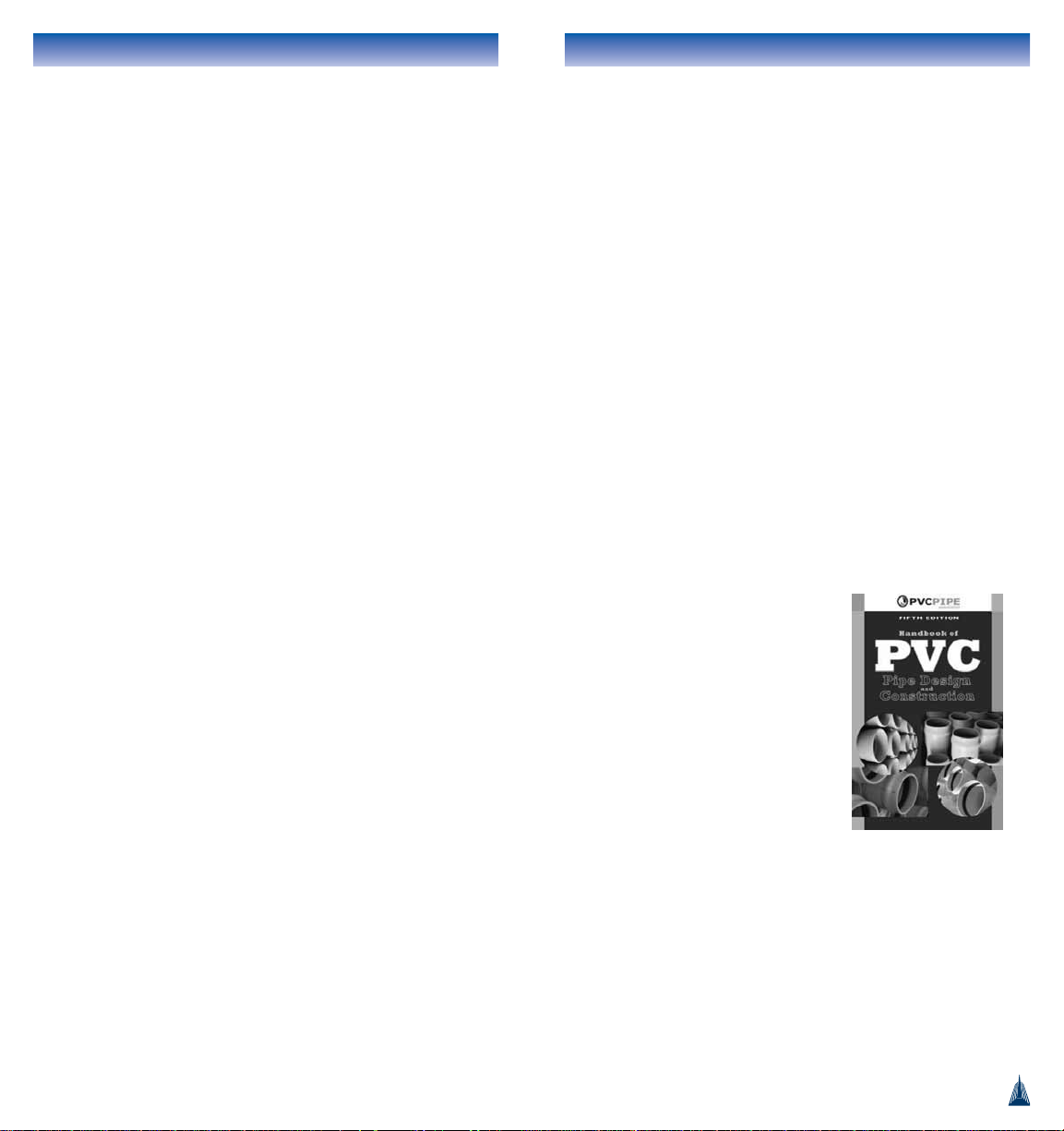
The Bottom of the Trench
The objective of bedding is to provide a continuous support for
the pipe at the required line and grade. Frozen material should
not be used to support or bed the pipe. At least 4" (100mm)
of bedding material should be placed under the pipe if rocky
conditions exist. The bedding may or may not be compacted,
but in any event the projecting bells of the pipe should be
properly relieved in the trench bottom so that the entire pipe
is evenly supported by the bedding. Where the trench bottom
is unstable (organic material, or "quick" sand or similar
material) the trench bottom should be over-excavated and
brought back to grade with approved material.
Often today, local labor codes require the use of a trench box
or sheeting to support the walls of an open trench. Removal of
9
PVC Pressure Pipe & Ftgs Installation Guide
TRENCH PREPARATION
Safety
Trenches can be dangerous places. The contractor is
responsible for ensuring that all applicable regulations have
been observed and that the protection of the workers and the
general public is provided.
Excavating and Preparing the Trench
The drawings and bid documents will specify the correct line
and grade to be established by the trenching operation. Aside
from these engineering considerations, good bedding practices
make sense for all types of pipes, including PVC.
The width of the top of the trench will be determined by local
conditions. But in the pipe zone the trench width should be
kept to a practical minimum.
The general rule is that the maximum width at the top of the
pipe should not be more than the outside diameter of the pipe
plus 24" (600mm). If trench width cannot be controlled and
will exceed the maximum then compacted backfill must be
provided for a distance of 2-1/2 pipe diameters to either side
of the pipe or to the trench wall, for pipe sizes up to 10"
(250mm). For larger sizes the compacted haunching material
should be placed one pipe diameter or 24" (600mm),
(whichever is greater) to either side of the pipe. This lateral
spacing will facilitate easy placement and shovel-slicing of
bedding material in the haunch zone of the trench. The
minimum distance required is 8" (200mm) on either side of
the pipe.
Keep the three basic operations close together: digging, pipe
laying and backfilling. The shortest practical stretch of open
trench reduces the possibility of problems associated with
water, frozen ground, impact damage, flotation, and traffic.
8
PVC Pressure Pipe & Ftgs Installation Guide
ASSEMBLING IPEX JOINTS
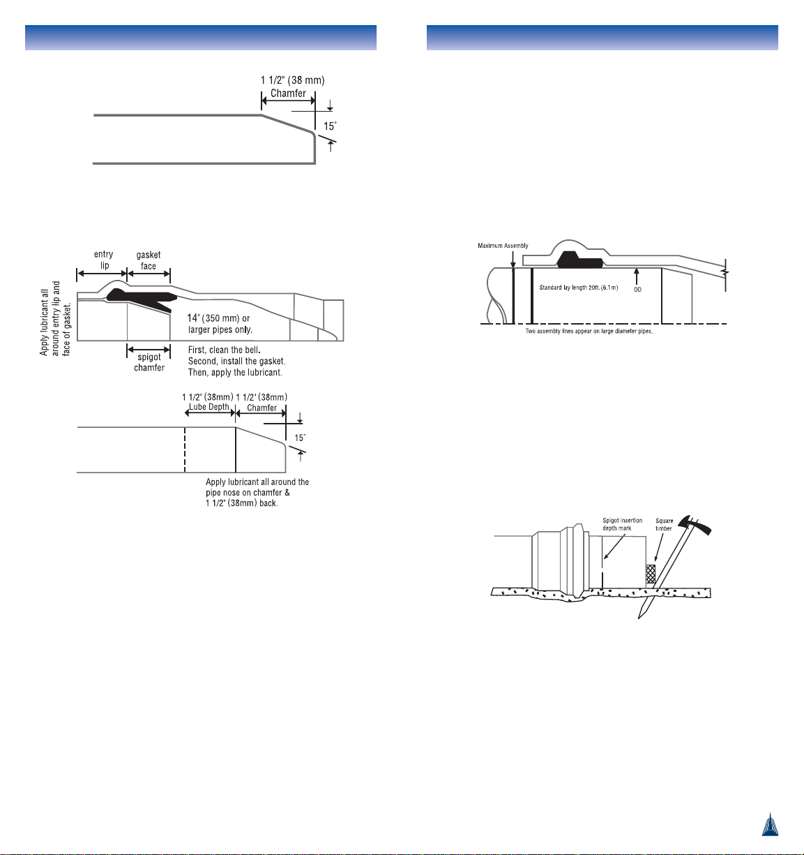
Preparation
All IPEX PVC pipe and fittings are prepared for assembly
as follows:
Keep both the spigot and the bell clean. It is good practice to
lay PVC pressure pipe with bells forward so that the assembly
operation will consist of pushing the spigot into the bell. This
will minimize the possibility of contaminating the surfaces
with foreign material. All assemblies should be concentric.
Use only IPEX PVC pipe lubricant. The use of substitute
lubricants may affect water quality or damage the gaskets.
For most pipes, gaskets are factory-installed.
If the gasket is not pre-installed: before inserting the gasket,
make sure that it is clean and that the bell groove is free of
any debris or dirt. Then carefully position the gasket in the
groove. Gaskets are not interchangeable – USE ONLY THE
GASKETS SUPPLIED BY IPEX.
If the gasket is already installed: it is usually not necessary to
remove the gasket for cleaning.
Clean the inside of the bell (including the face of the gasket),
and the outside of the spigot with a rag, brush, or paper towel
to remove any dirt or foreign material before assembling.
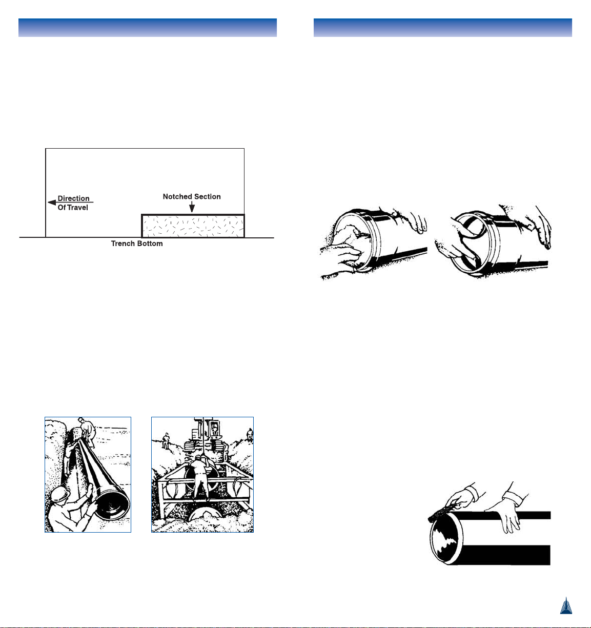
The pipe is shipped with
a chamfer on the end of
the spigot. If there is no
chamfer, follow the
example of a factorymade spigot and
machine a suitable
chamfer.
11
PVC Pressure Pipe & Ftgs Installation Guide
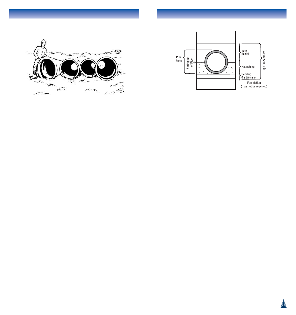
these supports after pipe installation may leave gaps in the
pipe zone of the trench. These voids should be filled in with
additional embedment material after sheeting removal. In
some cases, it may be desirable to leave the sheeting in place
as part of the pipe embedment, or to use a 'notched' trench
box as shown below.
LOWERING THE PIPE AND FITTINGS INTO THE
TRENCH
Place the pipe and fittings into the trench using ropes and
skids, slings on the backhoe bucket, or by hand. Do not throw
the pipe or fittings into the trench or allow any part of the pipe
to take an unrestrained fall onto the trench bottom. At this
point the pipe and other accessories are in a good position for
final inspection. Ensure there are no damaged materials before
assembly begins.
10
Form the chamfer using a beveling
tool, hand rasp or disk cutter.
PVC Pressure Pipe & Ftgs Installation Guide
the pipe. A two by four or a plank should be placed between
the backhoe bucket and the edge of the pipe. The use of a
backhoe bucket has the disadvantage that the backhoe
operator is unable to see clearly when the assembly is
complete. Thus, a helper should be located near the joint to
signal when the assembly is complete.
NOTE:
Factory-made assembly lines on the pipe do not indicate
correct assembly to fittings.
OVER-ASSEMBLY OF THE JOINT COULD DAMAGE THE BELL
OF THIS OR ADJACENT PIPE LENGTHS. MAKE SURE THAT
PREVIOUSLY ASSEMBLED JOINTS REMAIN UNDISTURBED.
If resistance is felt to the assembly, it may mean that the
sealing gasket has somehow become dislodged. If so, the joint
should be disassembled, cleaned, and reconstructed in
accordance with the methods given above.
NOTE:
If there are no assembly lines visible on the pipe, the
minimum and maximum insertion depths shown on pgs. 19,
20, 21 & 22 should be marked on the pipe by hand.
For Sizes Over 36 inches (900mm)
Consideration should be given to the use of come-along
devices for assembly of the gasketed joint in these sizes. A
minimum of 1/2" (13mm) thickness of chain should be used.
IPEX also has available a motorized come-along apparatus
known as a Pipe Puller. Contact IPEX for details.
13
PVC Pressure Pipe & Ftgs Installation Guide
Lubrication
Apply a thin coating of lubricant (equivalent to a brushed
coating) using a glove, a rag, or a paint brush. The area to be
covered is as follows:
Assembly
Keeping the spigot out of the dirt, position it so that the
chamfer is resting against the gasket in the bell. Push the
spigot into the bell until the assembly line on the spigot is
even with the edge of the bell. If there are two assembly lines
the edge of the bell should line up between them.
The assembly effort can be delivered by hand in small
diameters with the aid of a twist as the spigot enters the bell,
or by using a bar and block. Other assembly methods include
lever pullers, hydraulic jacks, and for large diameter pipes the
IPEX Pipe Puller.
Where mechanical means, such as a backhoe, are used, the
assembly effort should not be applied directly to the edge of
12
*For proper lubricant usage refer to page 74.
NOTE: Gasket drawings are for information only.
Actual gaskets may vary.
PVC Pressure Pipe & Ftgs Installation Guide
Deflecting the Joint
The procedure for offsetting the IPEX gasketed joint is shown
below.
Do not combine this method with bending the pipe barrel.
1. Make a concentric assembly, but push the spigot into the
bell only to a point about 1/2 inch (13mm) short of the
reference line (the first reference line if there are two).
This incomplete assembly permits more movement of the
end of the pipe at the bottom of the bell.
2. Without delay, shift the loose bell end of the assembled
length by not more than the following recommended
maximum offsets. Use only manual effort.
MAXIMUM RECOMMENDED OFFSETS, TO ACHIEVE
MINIMUM CURVE RADIUS BY DEFLECTING A STRAIGHT
LENGTH OF PIPE AT THE JOINT (FOR ALL PRODUCTS)
** Bell-by-Bell fittings such as tees and couplings offer a
total of 2º deflection per fitting.
15
PVC Pressure Pipe & Ftgs Installation Guide
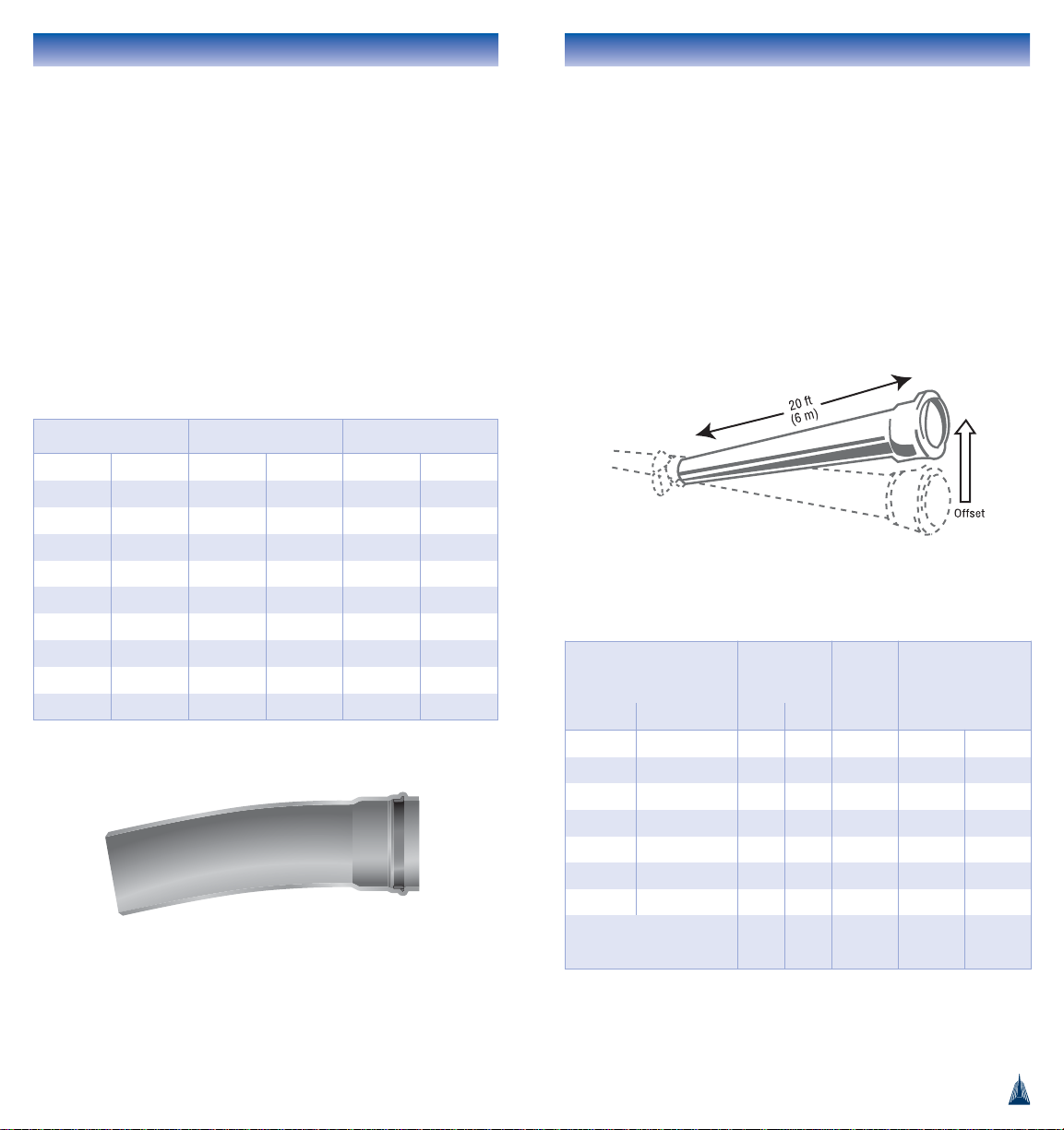
CURVATURE OF THE PIPELINE
There are three common methods used to achieve changes in
direction with IPEX Pressure Pipe. They are 1) using PVC
fittings, 2) deflecting the joint, 3) bending the pipe barrel.
Using PVC Fittings
Pipeline curvatures can be achieved by using IPEX PVC
fittings. Standard elbows for molded fittings include 22 1/2,
45 and 90 degrees. Blue Brute
TM
or Cycle ToughTMfittings
offer an additional 1º of offset capacity at each bell. To
achieve greater changes in direction, IPEX offers 5° CIOD
bends in DR18 up to 24 inches (600 mm). The cut lengths
and radii are as follows:
14
Pipe Size Max Offset
Angle at
One Bell
Resulting Radius of
Curvature Using
20ft (6m) Lengths
in mm in mm
4 100 121/2 320 3º 382 ft 116 m
6 150 121/2 320 3º 382 ft 116 m
8 200 121/2 320 3º 382 ft 116 m
10 250 121/2 320 3º 382 ft 116 m
12 300 101/2 270 2.5º 458 ft 140 m
14 - 24 350 - 600 61/4 160 1.5º 764 ft 233 m
30 - 48 750 - 1200 4 100 1.0º 1146 ft 349 m
At Molded PVC Fittings
(all sizes)
4 100 1.0º** 1146 ft 349 m
Size Cut Length Radius
in mm in mm ft m
6 150 36 910 22 6.7
8 200 36 910 21 6.3
10 250 42 1070 26 7.9
12 300 48 1220 30 9.2
14 350 60 1520 40 12.2
16 400 72 1830 48 14.6
18 450 74 1870 49 14.8
20 500 82 2080 54 16.5
24 600 98 2480 67 20.3
PVC Pressure Pipe & Ftgs Installation Guide
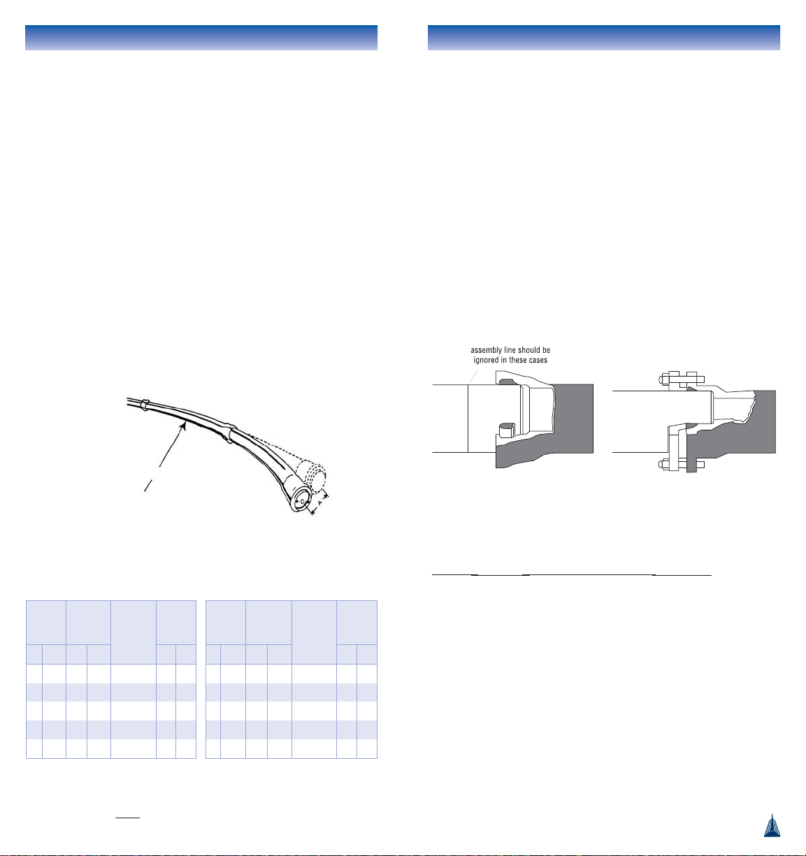
ASSEMBLING TO IRON APPURTENANCES
Assembling to Cast Iron Fittings
The bells of both mechanical joint and push-fit iron fittings
are much shallower than the bells of IPEX pipe. For this
reason, the assembly line on the pipe spigot is of no value as
an indicator of proper assembly to cast iron fittings. In order to
fully engage the gasket of the iron push-fit bell, the chamfer of
the PVC pipe spigot should be essentially removed. Leave only
an eighth of an inch of chamfer when assembling to push-fit
joints. When completing the mechanical joint, remove all the
pipe chamfer and reduce the torque requirements quoted for
iron assemblies. The gasket used in mechanical joint fittings
should be duck tipped. Do not attempt to deflect joints made
to iron fittings.
Assembling to Butterfly Valves
When heavy-wall PVC pipes, such as DR14, are assembled to
butterfly valves there is a possibility that the inside edge of
the pipe may interfere with the swing of the disc. In this case,
a 1/2" (13mm) 45° chamfer on the inside edge of the pipe
spigot will provide the needed clearance.
17
PVC Pressure Pipe & Ftgs Installation Guide
Bending the Pipe Barrel
Smaller diameters of IPEX PVC pressure pipes can be laid to
the line of curved trench by bending the pipe barrel into a
curved shape. The procedure is as follows:
1. Make a concentric assembly in the usual way. Keep the
spigot in straight alignment with the bell.
2. Place compacted backfill around the assembled joint to
restrict its movement while the curvature is being made.
3. Place compacted backfill at the inside of the curve, at the
mid-point of the pipe length, to form a fulcrum.
4. Using only manual effort, move the leading bell of the pipe
length to be curved by no more than the offset distance
shown in the following table.
5. Do not cut service taps into bent PVC pipe. Tapping bent
PVCO pipe is permitted.
NOTE: Bent pipes should be clearly marked along their length
to avoid the possibility that they will be tapped in the future.
MAXIMUM RECOMMENDED OFFSET, A, TO ACHIEVE
MINIMUM RADII OF CURVATURE BY BENDING THE BARREL
OF 20 ft (6 m) LENGTHS
16
Radius of Curvature
A = Offset (Varies
according to size.
See table.)
* SDR and DR both refer to the outside diameter of the pipe divided
by pipe thickness:
O.D.
t
Pipe SizeDMax Offset
A
Resulting
Angle of
Deflection
Resulting
Radius of
Curvature
in mm in mm ft m
4 100 32 813 7.6º 75 23
6 150 22 560 5.2º 111 34
8 200 17 430 4.0º 144 44
10 250 13 330 3.2º 179 55
12 300 11 280 2.7º 213 65
Pipe SizeDMax
Offset
Resulting
Angle of
Deflection
Resulting
Radius of
Curvature
in mm in mm ft m
4 100 24 600 5.7º 100 30
6 150 17 430 4.0º 144 44
8 200 13 300 3.0º 188 58
10 250 10 254 2.5º 232 71
12 300 8.7 221 2.1º 275 84
CIOD Pipe – Blue Brute
TM
& Bionax®C909 Pipe
NOTE: Minimum radius is
approximately 250 times nominal OD
IPS OD Pipe – Cycle Tough
TM
F1483 Pipe
NOTE: Minimum radius is
approximately 200 times nominal OD
Leave a slight chamfer on CIOD
PVC pipe assembled to push-fit
cast iron fittings. Bottom the pipe
in the iron bells.
Square-cut the edge of PVC
pipes assembled to M-J cast
iron fittings.
Pipe Size Bolt Torque
4"-24" (100 - 600mm) 70 - 80 ft lbs (95-108N-m)
30"-36" (750 - 900mm) 90 - 100 ft lbs (122-136N-m)
42"-48" (1050 - 1200mm) 125 - 150 ft lbs (170-200N-m)
PVC Pressure Pipe & Ftgs Installation Guide
19
PVC Pressure Pipe & Ftgs Installation Guide
CUTTING AND CHAMFERING
THE PIPE
Cutting
A square cut is important. With smaller diameter pipes a
mitre-box can be used with a hand saw to complete the cut.
With large diameter pipes, which are difficult to lift, select a
flat piece of ground and roll the pipe across the ground while
scribing a cutting line on the pipe wall with a felt pen. This
line should be placed carefully to ensure a square cut. The
rolling action may also be used to feed a power tool along the
cutting line. Use an abrasive disc or steel saw blade while not
force-feeding the tool in a manner that causes burns.
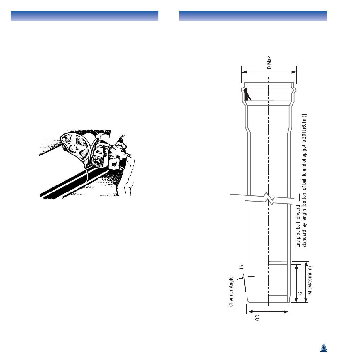
Chamfering
The chamfer on pipe supplied from the factory is about 15°.
Using the factory pipe as a guide, the cut length should be
chamfered to approximately the same angle and distance
back. There are a number of ways of chamfering pipe: A power
sander or abrasive disc, a router, and a rasp or file, may be
used. When assembling to iron fittings, only a short bevel of
about 1/8" (3mm) or so should be made to the cut edge.
To ensure correct assembly of cut pipe to IPEX joints, mark an
assembly line on the spigot end with a felt pen. Use other
pipe lengths as a guide, or use the dimensions in the tables
on the next pages.
18
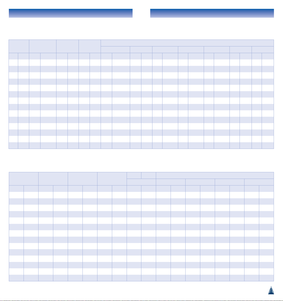
DIMENSIONS
Pipe Dimensions
(Minimum)
PVC Pressure Pipe & Ftgs Installation Guide
21
PVC Pressure Pipe & Ftgs Installation Guide
20
Nominal
Size
Average OD
Minimum
Insertion C
Maximum
Insertion M
D max
DR 51 DR 41 DR 32.5 DR 25 DR 18 DR 14
in mm in mm in mm in mm in mm in mm in mm in mm in mm in mm
4 100 4.8 122 5.8 148 - - - - - - - - 6.0 152.35 6.1 156.18 6.3 160.08
6 150 6.9 175 6.4 163 - - - - - - - - 8.3 210.04 8.5 215.55 8.7 221.16
8 200 9.1 230 7.1 181 - - - - - - - - 10.8 273.07 11.0 280.29 11.3 287.66
10 250 11.1 282 7.6 192 - - - - - - - - 13.3 338.61 13.7 347.47 14.0 356.50
12 300 13.2 335 8.1 207 - - - - - - - - 15.6 395.63 16.0 406.15 16.4 416.90
14 350 15.3 388.6 8.0 203 9.0 229 - - 17.7 449.84 18.0 456.34 18.2 462.08 18.7 474.28 19.2 486.73
16 400 17.4 442.0 10.0 254 11.0 279 - - 20.0 508.80 20.3 516.20 20.6 522.72 21.1 536.59 21.7 550.75
18 450 19.5 495.3 10.5 267 11.5 292 22.0 558.5 22.3 567.56 22.7 575.85 23.0 583.16 23.6 598.71 - 20 500 21.6 548.6 11.5 292 12.5 318 22.2 562.78 24.9 632.41 25.3 641.60 25.6 649.70 26.3 666.92 - 24 600 25.8 655.3 13.0 330 14.0 356 29.3 745.41 29.6 751.74 29.9 760.17 30.4 772.38 31.2 792.96 - 30 750 32.0 812.8 14.5 368 15.5 394 35.8 908.98 36.1 916.83 36.5 927.29 37.1 942.43 ---36 900 38.3 972.8 15.5 393 16.5 419 42.5 1079.90 42.9 1089.29 43.4 1101.82 44.1 1119.94 - - - 42 1050 44.5 1130.3 16.0 406 17.0 432 48.8 1240.00 49.4 1255.00 50.0 1270.00 50.9 1293.00 ---48 1200 50.8 1290.3 17.0 432 18.0 457 55.5 1409.00 56.1 1424.00 56.7 1441.00 57.8 1467.00 - - - -
Dimensions of Blue Brute and IPEX Centurion
Pressure Pipes with CIOD's
Nominal Size Average OD
Minimum
Insertion C
Maximum
Insertion M
D max
DR 41 DR 32.5 DR 26 DR 21
in mm in mm in mm in mm in mm in mm in mm in mm
1-1/2 40 1.900 48.3 3.3 83 - - ----2.75 70.00 2.75 70.00
1 50 2.375 60.4 3.7 93 - - - - - - 3.32 84.00 3.37 85.00
2-1/2 65 2.875 73.0 4.2 106 - - ----3.82 97.00 3.87 98.00
3 75 3.500 88.9 4.8 121 - - - - - - 4.54 115.00 4.60 117.00
4 100 4.500 114.3 4.8 123 - - 5.5 139.36 5.5 140.83 5.60 142.61 5.70 144.72
6 150 6.625 168.3 4.8 123 - - 7.8 198.16 7.9 200.33 8.00 202.94 8.10 206.05
8 200 8.625 219.1 5.4 138 - - 10.1 255.39 10.2 258.21 10.30 261.61 10.50 265.66
10 250 10.750 273.1 6.3 161 - - 12.6 319.25 12.7 322.77 12.90 372.01 13.10 332.06
12 300 12.750 323.9 6.5 165 - - 14.7 372.81 14.8 376.98 15.00 382.01 15.30 388.00
14 350 14.000 355.6 7.0 178 8.0 203 16.2 411.33 16.4 415.91 16.60 421.43 46.90 428.00
16 400 16.000 406.4 8.9 227 9.9 252 18.5 469.84 18.7 475.07 19.00 481.38 19.20 488.89
18 450 18.000 457.2 9.9 252 10.9 276 20.7 526.06 20.9 531.95 21.20 539.05 21.60 547.50
20 500 20.000 508.0 10.7 272 11.7 297 23.1 585.84 23.3 592.38 23.60 600.26 24.00 609.65
24 600 24.000 609.6 11.7 296 12.7 322 27.5 697.78 27.8 705.63 28.20 715.10 28.60 726.37
Dimensions of Cycle Tough Pressure Pipes
with IPS OD's
PVC Pressure Pipe & Ftgs Installation Guide
Cycle Tough PVC Pipe:
Iron Pipe Size (IPS) Outside Diameter
IPEX Series gasketed pipes with IPS O.D. (equivalent to steel
pipe outside diameters) are available in sizes ranging from
1-1/2" (40mm) through 24" (600mm). All IPEX Series pipe is
certified to CSA B137.3 and conforms fully to ASTM D 2241.
These pressure rated pipes fit directly into IPS Cycle Tough
injection molded fittings. They also fit into Blue Brute or iron
fittings by using transition gaskets or adapters. These adapters
are available with either spigot or bell ends and are
approximately 24" (600mm) long.
Bionax PVCO Pipe: Cast Iron Outside
Diameter (CIOD)
This is pipe associated with the American Water Works
Association Standard C909. IPEX offers CIOD sizes 4, 6, 8,
10, and 12" (100, 150, 200, 250, and 300 mm) in Pressure
Class 235. Bionax CIOD pressure pipes are third-party
certified to the AWWA C909 standard.
This pipe also is associated with Canadian Standards
Association B137.3.1. IPEX offers CIOD sizes 4, 6, 8, 10, and
12" (100, 150, 200, 250 mm, and 300 mm) in Pressure
Rated 1620 kPa. Bionax CIOD pressure pipes are third-party
certified to the CSA B137.3.1 standard.
Pipes having CIOD are adaptable directly to molded or
fabricated PVC fittings, cast iron fittings, valves, and other
appurtenances. For the iron fittings and valves, preparation of
the Bionax pipe end must reflect the reduced insertion depth
of these fittings.
23
PVC Pressure Pipe & Ftgs Installation Guide
OUTSIDE DIAMETER CONSIDERATIONS
IPEX pressure pipes are available in two different outside
diameter regimes in most nominal sizes. These are Cast Iron
(CIOD) and Iron Pipe Size (IPS) Outside Diameters. The
dimensions for each configuration are shown in the tables on
pages 20, 21, and 22.
Blue Brute & Centurion PVC Pipe:
Cast Iron Outside Diameter (CIOD)
These are the pipe and fittings normally associated with the
American Water Works Association Standards C900, C905 and
C907. IPEX offers sizes of 4, 6, 8, 10 and 12" (100, 150,
200, 250 and 300mm) with CIOD's in Pressure Class (PC)
165 (DR25), PC 235 (DR18) and PC 305 (DR14). Also
available are pipe sizes 14" (350mm) through 48" (1200mm)
with CIOD's in PC 80 (DR51), PC100 (DR41), PC125
(DR32.5), PC165 (DR25) and PC235 (DR18, to 24" only). All
CIOD PVC Pressure Pipes by IPEX are certified to CSA B137.3
and meet AWWA standards.
Pipes having CIOD are adaptable directly to molded or
fabricated PVC fittings, cast iron fittings, valves and other
appurtenances. For the iron fittings and valves, preparation of
the PVC pipe end must reflect the reduced insertion depth of
these fittings.
22
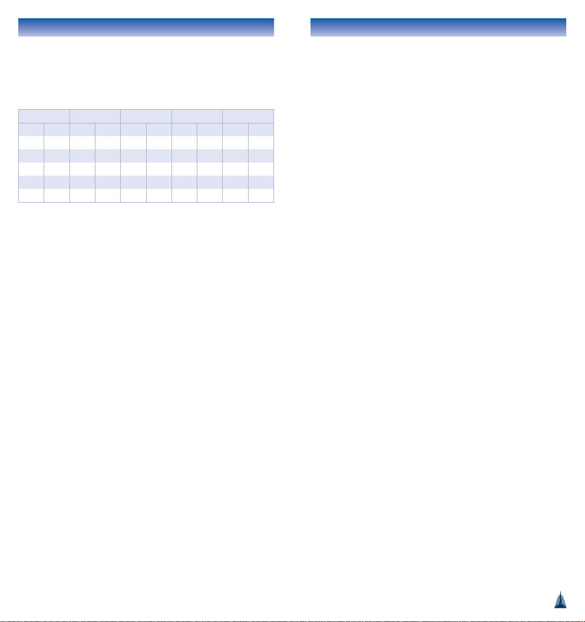
Nominal Size Average OD Insertion D max Average ID
in mm in mm in mm in mm in mm
4 100 4.80 122 5.43 138 6.10 155 4.48 114
6 150 6.90 175 5.94 151 8.49 216 6.44 164
8 200 9.05 230 6.57 167 10.83 275 8.45 215
10 250 11.10 282 7.05 179 13.33 339 10.37 263
12 300 13.20 335 7.76 197 15.60 396 12.33 313
Dimensions of Bionax PVCO Pressure Pipes with
CIODs
PC/PR 1620 kPa (235 psi)
 Loading...