

Page 1

Volume III:
Acid Waste
Piping Systems
Industrial Technical
Manual Series
TWELFTH EDITION
IPEX ACID WASTE PIPING SYSTEMS
Enfield®Electrofusion Acid Waste System
Labline
®
Mechanical Joint Acid Waste System
Plenumline™ Mechanical Joint Acid Waste System
Floway
TM
Acid Resistant Floor Drains
Neutratank
®
Neutralization Tanks
Neutrasystem 2
TM
pH Monitoring, Recording,
and Alarm System
Page 2

IPEX Acid Waste Piping Systems
Industrial Technical Manual Series
Vol. III, 12th Edition
© 2016 by IPEX. All rights reserved. No part of this book may
be used or reproduced in any manner whatsoever without prior
written permission.
The information contained here within is based on current
information and product design at the time of publication and is
subject to change without notification. IPEX does not guarantee or
warranty the accuracy, suitability for particular applications, or
results to be obtained therefrom.
Page 3
ABOUT IPEX
At IPEX, we have been manufacturing non-metallic pipe and fittings since 1951. We formulate our own compounds and
maintain strict quality control during production. Our products are made available for customers thanks to a network of
regional stocking locations throughout North America. We offer a wide variety of systems including complete lines of piping,
fittings, valves and custom-fabricated items.
More importantly, we are committed to meeting our customers’ needs. As a leader in the plastic piping industry, IPEX
continually develops new products, modernizes manufacturing facilities and acquires innovative process technology. In addition,
our staff take pride in their work, making available to customers their extensive thermoplastic knowledge and field experience.
IPEX personnel are committed to improving the safety, reliability and performance of thermoplastic materials. We are involved in
several standards committees and are members of and/or comply with the organizations listed on this page.
For specific details about any IPEX product, contact our customer service department.
Page 4
SAFETY ALERTS
Engineered thermoplastics are safe inert materials that do not pose any significant safety or environmental hazards during
handling or installation. However, improper installation or use can result in personal injury and/or property damage. It is
important to be aware of and to recognize safety alert messages as they appear in this manual.
The types of safety alert messages are described below.
This safety alert symbol indicates important safety messages in this manual.
When you see this symbol be alert to the possibility of personal injury and
carefully read and fully understand the message that follows.
WARNING
CAUTION
Note: The use of the word “NOTE” signifies special instructions which are important but
not related to hazards.
“CAUTION” identifies hazards or unsafe practices
which can result in minor injury or product or property
damage if instructions, including recommended
precautions, are not followed.
“WARNING” identifies hazards or unsafe practices
which can result in severe personal injury or death if
instructions, including recommended precautions, are
not followed.
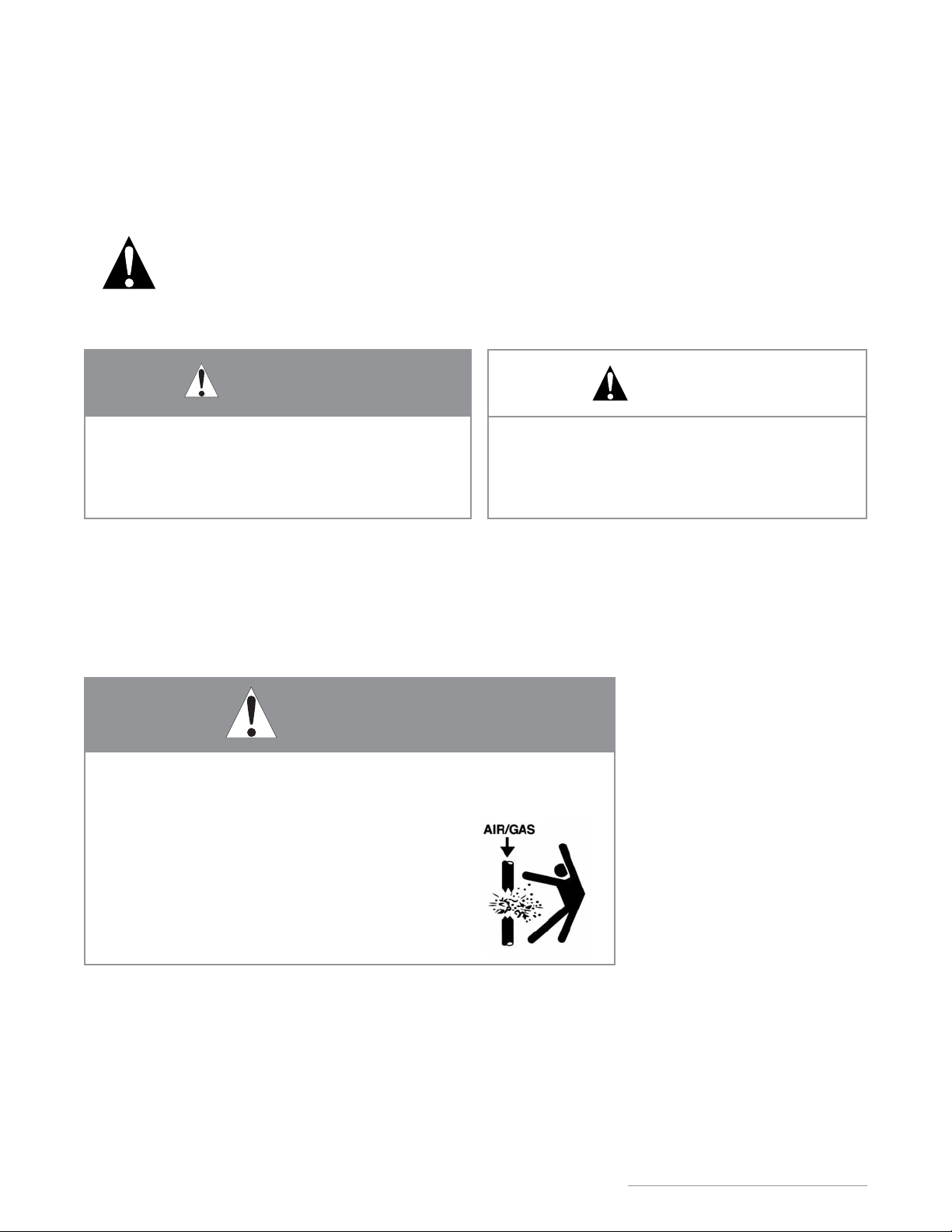
• NEVER use compressed air or gas in Enfield, Labline, or
Plenumline pipes, fittings, or accessories.
• NEVER test Enfield, Labline, or Plenumline systems with
compressed air or gas, or air-over-water boosters.
• ONLY use Enfield, Labline, or Plenumline systems for
approved chemicals.
Use of compressed air or gas in PP or PVDF pipe and fittings can result in
explosive failures and cause severe injury or death.
CAUTION
WARNING
For the materials described in this manual in acid waste applications, the following
warning applies.
i
IPEX Acid Waste Piping Systems
Page 5

ii
IPEX Acid Waste Piping Systems
NOTES
Page 6

CONTENTS
Acid Waste Piping Systems Manual
About IPEX
Safety Alerts . . . . . . . . . . . . . . . . . . . . . . . . . . . . . . . . . . . . . . . . . . . . . . . . .i
Section One: General Information
Overview . . . . . . . . . . . . . . . . . . . . . . . . . . . . . . . . . . . . . . . . . . . . . . . . . . . 1
IPEX Acid Waste Systems . . . . . . . . . . . . . . . . . . . . . . . . . . . . . . . . . . . . . . . 2
Benefits . . . . . . . . . . . . . . . . . . . . . . . . . . . . . . . . . . . . . . . . . . . . . . . . . . . 4
Material Description . . . . . . . . . . . . . . . . . . . . . . . . . . . . . . . . . . . . . . . . . . 7
Section Two: Dimensions
Pipe Dimensions . . . . . . . . . . . . . . . . . . . . . . . . . . . . . . . . . . . . . . . . . . . . . 9
Enfield Fitting Dimensions . . . . . . . . . . . . . . . . . . . . . . . . . . . . . . . . . . . . . 10
Labline and Plenumline Fitting Dimensions . . . . . . . . . . . . . . . . . . . . . . . . . 24
Accessories . . . . . . . . . . . . . . . . . . . . . . . . . . . . . . . . . . . . . . . . . . . . . . . . 32
Floway Polypropylene Drain Dimensions . . . . . . . . . . . . . . . . . . . . . . . . . . . 33
Floway Adjustable Acid Waste Cleanout w/ Nickel-Bronze Cover . . . . . . . . . . . 37
Standard Bolt Pattern and Dimensions . . . . . . . . . . . . . . . . . . . . . . . . . . . . 38
Section Three: Design Considerations
Expansion and Contraction . . . . . . . . . . . . . . . . . . . . . . . . . . . . . . . . . . . . . 39
System Sizing . . . . . . . . . . . . . . . . . . . . . . . . . . . . . . . . . . . . . . . . . . . . . . 43
Thermal Conductivity . . . . . . . . . . . . . . . . . . . . . . . . . . . . . . . . . . . . . . . . . 43
Pipe Supports and Support Spacing . . . . . . . . . . . . . . . . . . . . . . . . . . . . . . 44
Pipe Clips and Hangers . . . . . . . . . . . . . . . . . . . . . . . . . . . . . . . . . . . . . . . 46
Handling and Storage . . . . . . . . . . . . . . . . . . . . . . . . . . . . . . . . . . . . . . . . 49
Below Ground Installation . . . . . . . . . . . . . . . . . . . . . . . . . . . . . . . . . . . . . 50
Section Four: Installation
Introduction . . . . . . . . . . . . . . . . . . . . . . . . . . . . . . . . . . . . . . . . . . . . . . . 51
Enfusion Hand Held Control Unit . . . . . . . . . . . . . . . . . . . . . . . . . . . . . . . . 51
Multiple Joint Fusion . . . . . . . . . . . . . . . . . . . . . . . . . . . . . . . . . . . . . . . . . 55
Fault Code Analysis . . . . . . . . . . . . . . . . . . . . . . . . . . . . . . . . . . . . . . . . . . 57
Enfield Testing . . . . . . . . . . . . . . . . . . . . . . . . . . . . . . . . . . . . . . . . . . . . . 59
Enfield Pipe Repair . . . . . . . . . . . . . . . . . . . . . . . . . . . . . . . . . . . . . . . . . . 61
Labline and Plenumline Joints . . . . . . . . . . . . . . . . . . . . . . . . . . . . . . . . . . 62
Labline and Plenumline Testing . . . . . . . . . . . . . . . . . . . . . . . . . . . . . . . . . 64
iii
IPEX Acid Waste Piping Systems
Page 7

Section Five: Additional Engineering Considerations
Return Air Plenum Guidelines . . . . . . . . . . . . . . . . . . . . . . . . . . . . . . . . . . 65
Return Air Plenum Options . . . . . . . . . . . . . . . . . . . . . . . . . . . . . . . . . . . . . 66
Adapting to Other Drainline Materials . . . . . . . . . . . . . . . . . . . . . . . . . . . . . 67
Typical Underbench Configurations . . . . . . . . . . . . . . . . . . . . . . . . . . . . . . . 68
Section Six: Dilution and Neutralization
Dilution Traps . . . . . . . . . . . . . . . . . . . . . . . . . . . . . . . . . . . . . . . . . . . . . . 71
Neutralization . . . . . . . . . . . . . . . . . . . . . . . . . . . . . . . . . . . . . . . . . . . . . . 72
Cylindrical Tanks . . . . . . . . . . . . . . . . . . . . . . . . . . . . . . . . . . . . . . . . . . . 73
Rectangular Tanks . . . . . . . . . . . . . . . . . . . . . . . . . . . . . . . . . . . . . . . . . . 75
Options and Accessories . . . . . . . . . . . . . . . . . . . . . . . . . . . . . . . . . . . . . . 77
Neutratank Extensions . . . . . . . . . . . . . . . . . . . . . . . . . . . . . . . . . . . . . . . . 78
Solids Interception . . . . . . . . . . . . . . . . . . . . . . . . . . . . . . . . . . . . . . . . . . 80
Neutrasystem 2 . . . . . . . . . . . . . . . . . . . . . . . . . . . . . . . . . . . . . . . . . . . . . 81
Neutralization Tank Sizing and Maintenance . . . . . . . . . . . . . . . . . . . . . . . . 83
Neutralization Tank Installation . . . . . . . . . . . . . . . . . . . . . . . . . . . . . . . . . . 85
Section Seven: Acid Waste System Specifications
Enfield Specifications . . . . . . . . . . . . . . . . . . . . . . . . . . . . . . . . . . . . . . . . 86
Labline Specifications . . . . . . . . . . . . . . . . . . . . . . . . . . . . . . . . . . . . . . . . 87
Plenumline Specifications . . . . . . . . . . . . . . . . . . . . . . . . . . . . . . . . . . . . . 88
Neutratank Neutralization Tank Specifications . . . . . . . . . . . . . . . . . . . . . . . 89
Monitoring System Specifications . . . . . . . . . . . . . . . . . . . . . . . . . . . . . . . . 89
Encase Double Containment Acid Waste Systems . . . . . . . . . . . . . . . . . . . . . 90
Appendix:
Conversion Charts . . . . . . . . . . . . . . . . . . . . . . . . . . . . . . . . . . . . . . . . . . . 91
iv
IPEX Acid Waste Piping Systems
Page 8
GENERAL
INFORMATION
1
IPEX Acid Waste Piping Systems
OVERVIEW
SECTION ONE: GENERAL INFORMATION
For more than 30 years, IPEX has provided laboratories throughout North America with complete acid waste systems
designed to handle a variety of chemicals. Our Enfield®electrofusion and Labline®mechanical-joint systems rank among the
most widely specified systems on the continent. Constructed from flame-retardant polypropylene, these systems offer a
comprehensive solution for virtually all chemical waste situations. IPEX PlenumlineTMis a robust acid waste system, made
from flame-retardant PVDF thermoplastic, designed for challenging conditions, including highly restrictive return air
plenum applications, and high-temperature corrosive chemical waste situations. In addition, each system features
advantages of its own:
• Enfield
®
offers polypro fittings, constructed with a heavy gauge resistance wire that is integral to the socket. These are
considered to be the premier fittings on the market.
• Both Labline
®
and PlenumlineTMcontain no-heat ElastolivesTMfor quick installation and high performance.
According to standards ASTM E84 and UL 723, piping installed in spaces used as return air plenums must have a flame
spread index of 25 or less, and a smoke development index of 50 or less. Plenumline
TM
not only meets these requirements, but
also provides designers and contractors with all the traditional benefits associated with thermoplastic systems, including high
impact resistance, flexibility, low cost installations, long-term reliability, and exceptional chemical resistance.
Third-party testing reveals that Flame Retardant PVDF exhibits a flame spread index of 5 and a smoke development index of
35, making it particularly well suited to plenum applications.
Where design parameters allow, Flame Retardant PVDF Plenumline
TM
components or standard Flame Retardant PP Enfield®and
Labline®components can be easily integrated into a single comprehensive acid waste system.
Our complete range of products for acid waste includes Neutratank
®
neutralization tanks, Neutrasystem2TMpH monitoring
equipment and FlowayTMdrains as well as EncaseTMdouble containment systems (contact IPEX for more information on double
containment).
This design and installation manual provides up-to-date comprehensive information about IPEX’s acid waste systems. By
combining laboratory test results with decades of field experience, IPEX has produced a manual suited to engineers,
contractors and distributors alike. All aspects of our acid waste systems are described here — from dimensional data through
to installation and testing procedures.
Page 9
IPEX ACID WASTE SYSTEMS
The IPEX Solution
Changing government
regulations and increasing
public desire to minimize
environmental pollution has
necessitated changes in the
way chemicals are
discharged from industrial and
commercial facilities.
IPEX has long been recognized
for having the highest quality,
most reliable and most
comprehensive chemical waste
systems available. Whether the
problem at hand has
necessitated the fast and
versatile Labline
®
or
Plenumline
TM
Mechanical Joint
piping systems, or the
microprocessor-controlled
Enfield
®
jointed system, the end
result has been repeatable,
trouble-free installations. From
an environmental perspective,
IPEX manufactures a patented,
modular construction double
containment piping system,
(Encase
TM
, for more information,
see Double Containment Piping
Systems Manual, Volume VI),
that can be used above and
below ground to eliminate the
possibility of chemical spillage
into the environment.
Neutratank
®
is used for
limestone neutralization of
chemical waste prior to
discharge into the sewer.
While this method of
neutralization is very effective,
there is a growing need
to verify that the chemical
discharge is continuously
within acceptable pH levels.
Neutrasystem 2
TM
meets this
need by analyzing the pH of
liquid flow, permanently
recording the pH levels
encountered, and giving visual
and audible alarms to warn
maintenance personnel when
the pH level is outside of the
acceptable range.
Maintenance personnel can
then address the situation
usually by inserting additional
limestone chips.
FRPP & NFRPP Pipe (1-1/2" to 12")
FR-PVDF Pipe (1-1/2" to 4")
Our flame retardant PP (green) and
PVDF (blue) and non-flame retardant
PP (black) Schedule 40 piping is
NSF-listed and certified to
CSA B181.3 by NSF. Our PP meets
ASTM F1412 and D4101 and our
PVDF meets ASTM F1673.
Enfield Fittings (1-1/2" to 12")
Enfield Fittings utilize the latest in joining technology. The NSF-listed fittings have a
nickel chrome electrical resistance wire integrally in place. Joining is completed by
energizing the nickel/chrome wire with a self-diagnostic, microprocessor-controlled,
Enfusion control unit which fuses the pipe/fitting surfaces together.
Neutratanks
Neutratanks are made of high-density polyethylene or polypropylene material with
one-piece rotationally molded, seamless construction. Neutratanks are available in
sizes from 5 gallons to 2,000 gallons to suit most potential design conditions.
IPEX Acid Waste Piping Systems
2
GENERAL
INFORMATION
Page 10
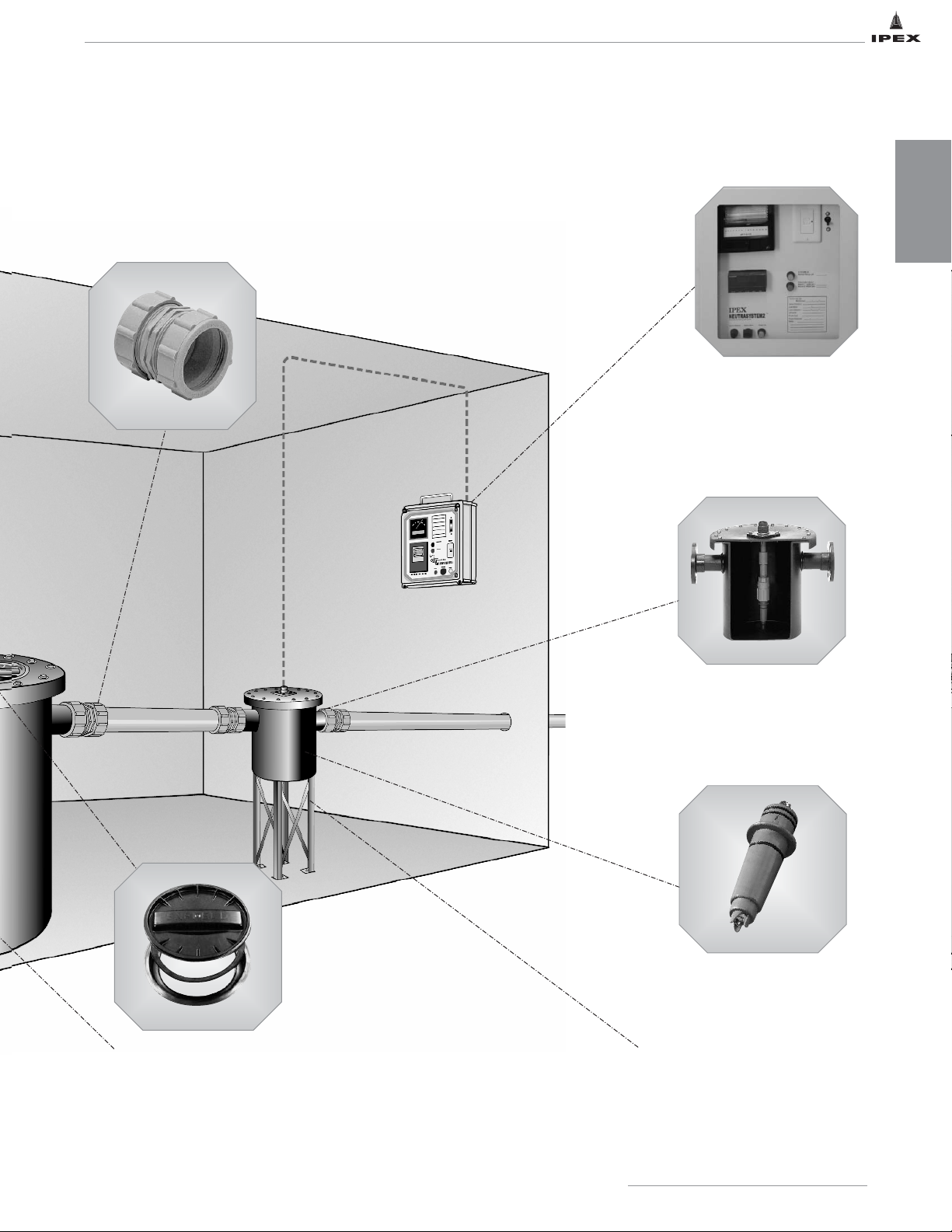
Sampling Tank
5-gallon, high-density polyethylene Sampling
Tank incorporates a bolt down cover and a
series 6510, extended life, removable pH
electrode which
measures the pH
level of the
chemical waste
before it is
discharged into
the sewer system.
Removable pH Electrode
The pH electrode is encapsulated in a
chemically resistant CPVC body with viton
O-rings. Its twist-lock design ensures quick,
easy removal and installation of the electrode.
The electrode is
fast responding,
highly efficient
and ensures
that pH
variations are
continuously
and accurately
measured.
Labline and Plenumline Fittings (1-1/2" to 4")
NSF listed, all-plastic construction Labline and Plenumline
Fittings allow for rapid (30 second) installation and ensure
trouble-free service. The joints can be easily made with our
new no-heat Elastolive, even in difficult areas, and can be
disassembled and re-used at a later date without spoiling
the fittings.
Limestone Chips
Neutratanks should be filled with an approved neutralization agent such as
limestone chips, one to three inches in size, to a level just below the tank
outlet. Water should then be added to the tank after placement of the
neutralization agent. During the course of neutralization, the limestone chips
will naturally be exhausted and require replenishment.
Sampling Tank Support
All sampling tanks must be independently
supported to avoid undue stressing of the
components (support supplied by others).
pH Monitor
The UL-listed, NEMA 4X, pH Monitor measures the
pH level of the chemical waste,
visually shows pH levels on an
analog display and permanently
records the results on a 31-day
strip chart recorder. The
monitor will audibly and
visually alarm maintenance
personnel when unacceptable
pH levels are sensed.
Threaded Manway
Neutratanks can be fitted with covers that incorporate
quick-start threads to enable rapid inspection of the
tank contents. This feature eliminates the time
consuming task of bolt removal and re-assembly
associated with conventional tank covers.
IPEX Acid Waste Piping Systems
3
GENERAL
INFORMATION
Page 11
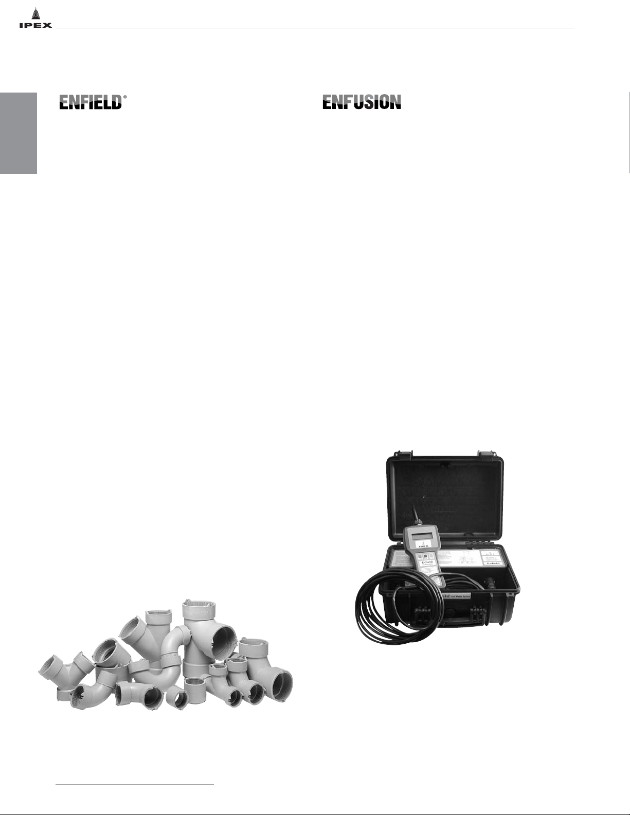
HAND HELD CONTROL UNIT
Enfield electrofusion fittings are molded with an integral
resistance wire in the socket, with jointing completed by
energizing the resistance wire via a microprocessor controlled
Enfusion Control Unit. The result of these innovations is an
unparalleled level of joint reliability and repeatability. Enfield
has proven over time that it produces the optimum level of
performance where it matters most - at the joint interface. It
offers unprecedented control of jointing - controlled fit,
controlled temperature and controlled time.
• Positive reliable joints made in 2 minutes
– installation time reduced
• Several joints can be made at one time
• Proven reliability for over a decade
• Enfield is manufactured from polypropylene which has an
operating temperature range from -10ºF (-23ºC) to 212ºF
(100ºC).* This allows systems to be flushed with boiling water
• Heavy gauge resistance wire molded into sockets
–no loose components, controlled fusion of joints
• Easy connecting heavy duty socket terminal posts complete
with protection ears
• Microprocessor controlled Enfusion unit ensures secure joints
and joint repeatability
• Matched system
- high quality pipe and fittings are matched to give ease of
installation and long term reliability
• Easy to install
– even in difficult areas
• Installed cost 50% less than glass
• Breakage factor eliminated
• Maintenance free
• NSF-approved, IAPMO-listed & CSA-certified,
meets ASTM F1412, D4101 and CSA B181.3
• Voltage sensing process will not start, (or will halt), unless
connections are secure and input/output voltages are in the
correct range
• Electronic stabilization of output from a wide range of input
voltages
• The Enfusion system is an 18 amp constant current system
that will generate a voltage ranging from 3 volts to 50 volts
• Automatic adjustment of fusion time for varying ambient
temperature conditions
• Self Diagnostic Unit, self monitors and automatically reads
current conditions
• Automatic alarm for cycle interruption
• May be able to re-start unit at cut-off time after fusion cycle
interruption
• Rugged, impact resistant construction
• Light-weight and easy to handle
• 2 lb hand held unit for ease of use
• Proven reliability in service
• Multiple joint fusion
• IP 65 gasketed case protects from the elements
GENERAL
INFORMATION
BENEFITS
4
IPEX Acid Waste Piping Systems
* Recommended constant operating temperature is 180ºF with intermittent 212ºF service.
Page 12
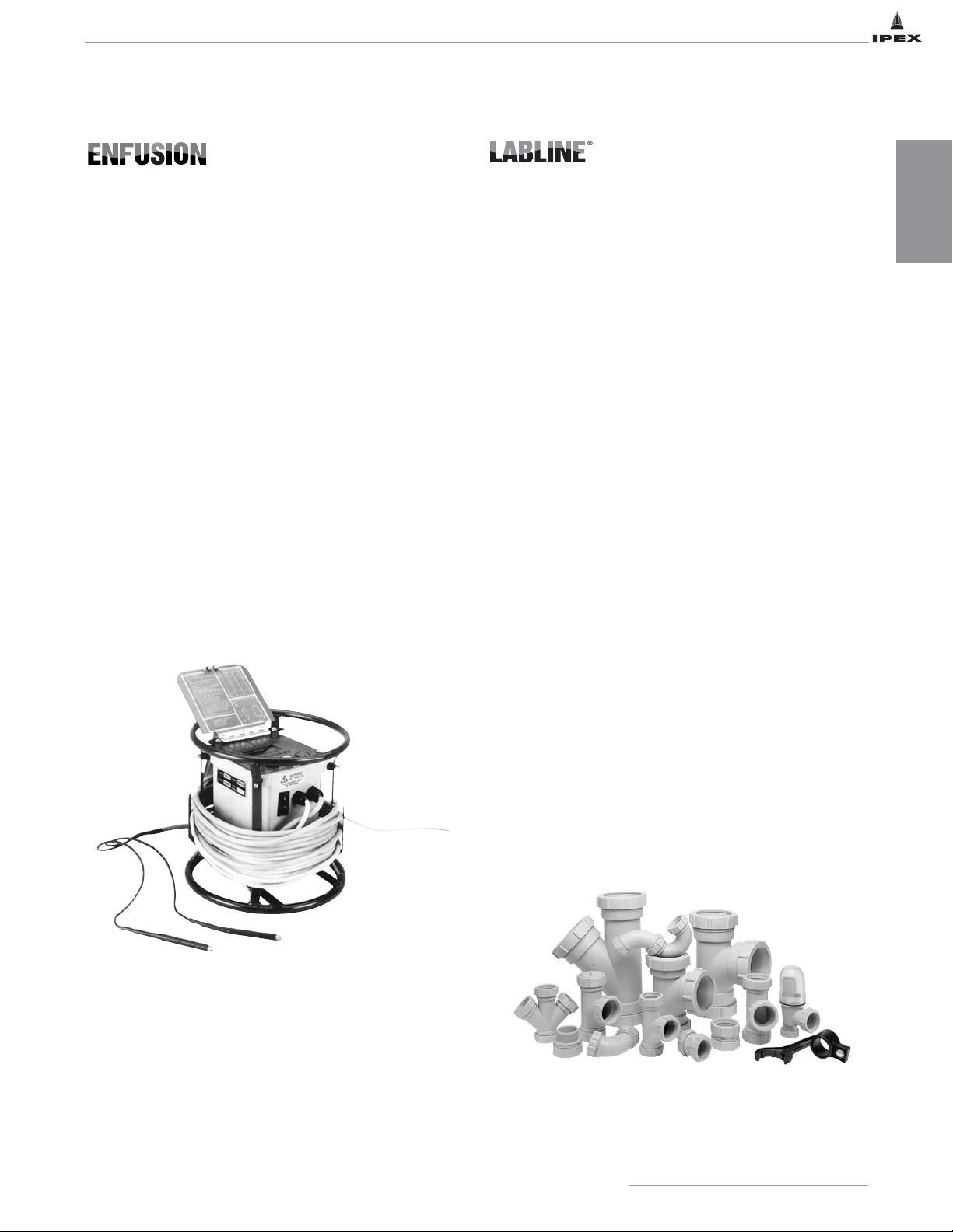
Labline (Mechanical Joint) has displaced the more expensive
and difficult to install glass and metal systems. Gone is the
need for fusing, caulking or welding of joints.
Joining of the
Labline System is complete in just 30 seconds
and once the
nut is locked into place, the end-user is assured of many
years of trouble-free service. Yet, because it is a mechanical
joint, the system can be easily dismantled and re-used,
making it ideal for modular designs and for systems that may
require re-modeling in the future.
• 30 second jointing – save on installation time
• Proven reliability for over 30 years
• Labline is manufactured from polypropylene which has
an operating temperature range from -10ºF (-23ºC) to
212ºF (100ºC).* This allows systems to be flushed with
boiling water
• All plastic construction
– no galvanic action, electrolysis or corrosion in the joint
• Simple, inexpensive, non-temperamental tools
• Easy to install, even in difficult areas
• Mastered by plumbers in minutes.
No pre-heating required to install olive
• System changes during installation can be done without
spoiling fittings
• Can be disassembled and re-used
• Ideal for modular systems
• Ideal for remodeling
• Matched system
– high quality pipe and fittings are matched to give ease of
installation and long term reliability
• NSF-approved, IAPMO-listed & CSA-certified,
meets ASTM F1412, D4101 and CSA B181.3
L2600 (Old Style Machine)
• Voltage sensing process will not start, (or will halt), unless
connections are secure and input/output voltages are in the
correct range
• Electronic stabilization of output from a wide range of
input voltages
• Automatic adjustment of fusion time for varying ambient
temperature conditions
• Self Diagnostic Unit, self monitors and automatically reads
current conditions
• Automatic alarm for cycle interruption
• May be able to re-start unit at cut-off time after fusion
cycle interruption
• Proven ruggedness, impact resistant construction, shock
absorbers and crash bars
• Light-weight and easy to handle
• Proven reliability in service
• UL and CSA approved control units
NOTE: It is recommended that you replace these L2600 machines
with newer models.
GENERAL
INFORMATION
5
IPEX Acid Waste Piping Systems
* Recommended constant operating temperature is 180ºF with intermittent 212ºF service.
Page 13

6
IPEX Acid Waste Piping Systems
In certain industries there is little margin for error; all
potential for accidents must be eliminated. This is
particularly important where radioactive fluid wastes or
particularly dangerous chemicals are being conveyed through
the waste drainage system.
While Enfield/Labline is the ideal material, our double
containment Encase system eliminates problems which may
arise from leakage, while at the same time giving a warning
that leakage is present in the system.
Encase Double Containment is part of a total integrated
single and dual containment approach to above and below
ground chemical waste drainage.
In below ground drainage work where the legislative
responsibility, environmental impact, and cost of
contamination of ground water supplies is of growing
concern, Encase Double Containment provides the highest
level of safety and integrity possible in handling such
materials.
Proven System
Encase double containment utilizes the proven Enfield
chemical waste drainage system as the primary and
secondary pipework carrier. The secondary pipework is a
larger diameter pipe which, holding the primary pipework
central with a series of spacers, is also fully sealed by the
electrofusion process.
The Enfield electrofusion jointing process has been proved
over the last 35 years in many installations throughout the
world. It has been confirmed to be superior to butt fusion
and other electrofusion methods.
Encase Double Containment systems are available with our
Centra-Guard detection system. For additional informaiton
on the Encase Double Containment Systems, please see
IPEX Technical Manual Volume VI: Double Containment
Piping Systems.
DOUBLE CONTAINMENT
GENERAL
INFORMATION
Plenumline mechanical joint acid waste systems easily
displace costly and difficult-to-install glass and metal
systems. With Plenumline, time-consuming methods
associated with conventional heavy and brittle systems are
replaced by a time proven mechanical joint that takes only
30 seconds to complete. Once the Plenumline nut is locked
in place, the end-user is assured of many years of troublefree service. In addition, mechanical joint systems can easily
be dismantled and re-used, making Plenumline ideal for
modular designs and future expansions.
• Ideally suited to plenum applications
• 30-second joints shorten installation time
• Manufactured from Flame Retardant PVDF, which has an
operating temperature range from -40°F (-40°C) to 285°F
(140°C). With this high upper limit, Plenumline systems can
be flushed with boiling water.
• All-plastic construction eliminates galvanic action, electrolysis
and corrosion in the joint.
• Easy to install, even in tight areas, by using simple,
inexpensive tools. Mechanical joints are mastered by
plumbers in minutes; no pre-heating is required to install the
new blue elastolive.
• Modularized design means Plenumline components can be
disassembled and re-used. In addition, system
modifications during installation can be performed without
damaging fittings.
• High-quality pipe and fittings are matched to simplify
installation and extend long-term reliability.
• Flame Retardant PVDF material exhibits a flame spread index
of 5 and smoke development index of 35 as tested in
accordance with ASTM E84 and UL723.
• IAPMO-listed, meets ASTM F1673, Standard specification
for Polyvinylidene Fluoride (PVDF) Corrosive Waste
Drainage Systems.
• NSF listed, certify to CSA B181.3.
• Listed to CAN/ULC-S102.2
Page 14
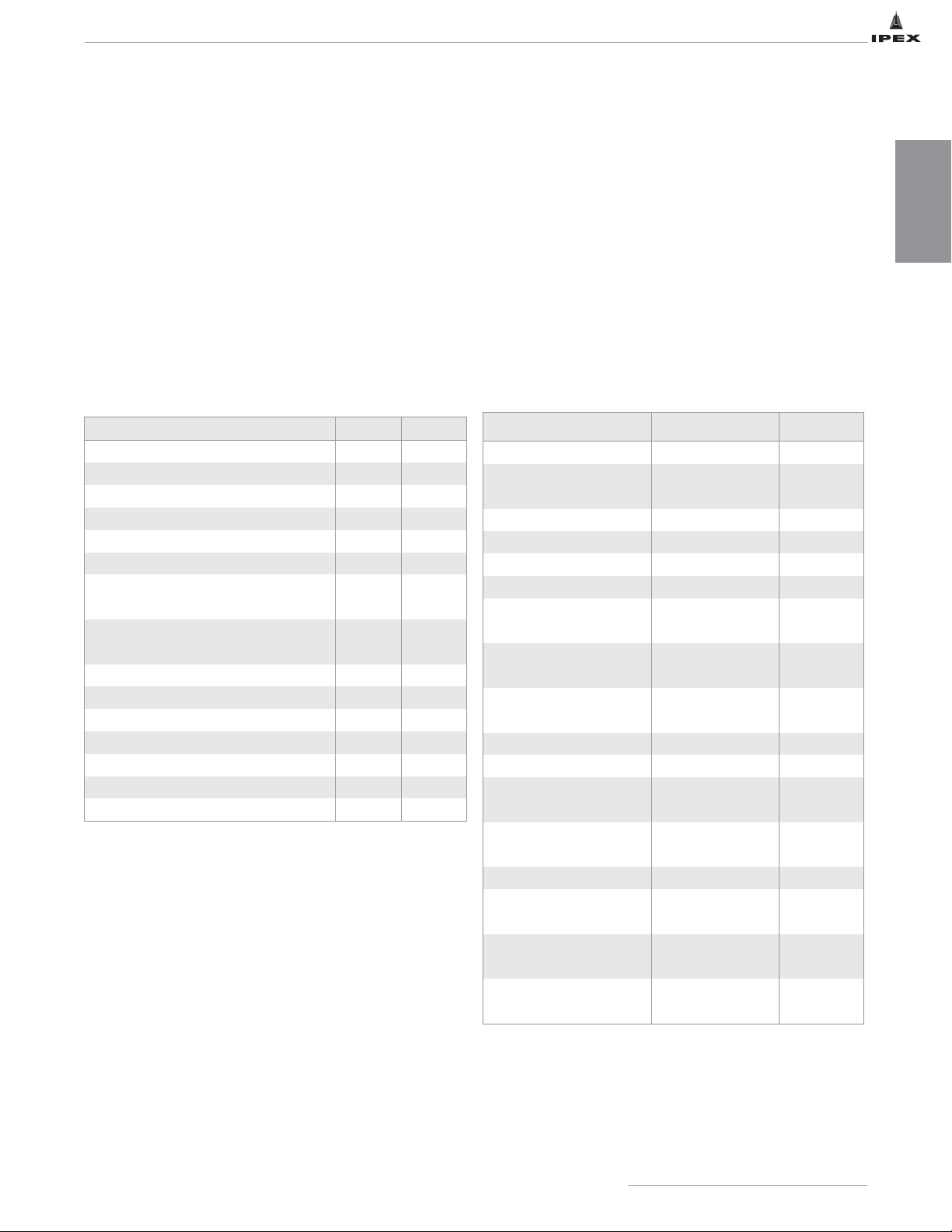
MATERIAL DESCRIPTION
IPEX’s flame retardant polypropylene (FRPP) material used to
manufacture Enfield pipe exceeds the requirements of
PP110 (pipe). Flame retardant polypropylene material used
to manufacture Enfield and Labline fittings exceed the
requirements of PP210 (fittings) material as described in
ASTM D4101. ASTM D4101 lists the following properties for
both pipe and fittings.
IPEX also offers our Acid Waste system in a non-flame
retardant polypro material. Enfield NFRPP pipe complies
with ASTM F1412 and the material used in the
manufacturing of the pipe complies with material
requirements of ASTM D4101.
GENERAL
INFORMATION
7
IPEX Acid Waste Piping Systems
ASTM D4101 Properties
Plenumline™ acid waste systems are constructed from flameretardant PVDF (polyvinylidene fluoride), a strong, abrasionresistant thermoplastic with excellent heat stability and
chemical resistance typical of fluorocarbon polymers.
Plenumline™ can be used in temperatures up to 285°F
(140°C) with a wide variety of acids, bases and organic
solvents, and is ideally suited for handling wet or dry
chlorine, bromine and other halogens.
No other thermoplastic piping material can approach the
combination of strength, chemical resistance and operating
temperature that FRPP piping systems can offer.
Physical Properties of FRPP
Property FRPP Standard
Specific Gravity 1.77 – 1.79 -
Water Absorption, %,
24 hrs. @ 73ºF
0.01 – 0.03 ASTM D570
Flexural modulus, psi 240,000 - 335,000 ASTM D790
Tensile yield elongation, % 5 – 10 ASTM D638
Tensile break elongation, % 50 – 200 ASTM D638
Tensile modulus, psi 200,000 - 335,000 ASTM D638
Deflection temperature
@ 264 psi, °F
221 – 239 ASTM D648
Deflection temperature
@ 66 psi, °F
257 – 284 ASTM D648
Impact strength (notched
Izod), ft-lb/in.
2 – 4 ASTM D256
Hardness, shore D 76 – 80
Melting temperature, °F 329 – 338
Coefficient of thermal
expansion, 10
-5
°F
6.6 – 8.0 ASTM D696
Thermal conductivity,
BTU-in/hr per ft
2
°F
1.18 – 1.32 ASTM D433
Burning rate V-0 UL/Bulletin 94
Limiting oxygen index 60
ASTM
D2868
Flame spread rating 5
UL723 /
ASTM E84
Smoke development
classification
35
UL723 /
ASTM E84
Property Value Standard
Specific Gravity .94 D1505
Tensile Yield Strength @ 2"/Min., psi 4400 D638
Flexural Modulus, psi 215,000 D790
Hardness, Rockwell R 100 D1706
Izod Impact, Notched, ft-lb/in. 1.0 D256
Coefficient of Linear Expansion, in/in/ºF 6 x 10⁻⁵D696
Heat Deflection Temperature
@ 66 psi load, ºF
220-240 D648
Heat Deflection Temperature
@ 264 psi load, ºF
195 D648
Water Absorption. 24 hrs., % .01 D570
Time of Burning (sec.) <5 D635
Extent of Burning (mm) <5
Burning Class V2 UL94
Maximum Smoke Density 62.0 D2843
Smoke Density Rating 40.1
Oxygen Index, % 28 D2863
Page 15

GENERAL
INFORMATION
8
IPEX Acid Waste Piping Systems
Chemical Resistance
Thermoplastics have outstanding resistance to a wide range
of chemical reagents. Such resistance is a function of both
temperature and concentration, and there are many reagents
which can be handled for limited temperature ranges and
concentrations.
Chemical resistance is often affected (and frequently
reduced) when handling a number of chemicals or
compounds containing impurities. When specific applications
are being considered, therefore, it is often worthwhile to
conduct tests using the actual fluid that will be used in
service.
PP is generally high in chemical resistance. It is capable of
handling a pH ranging from 1 to 13 being resistant to
organic solvents as well as acids and alkalies. Due to its
general sensitivity to oxidizing agents, special care must be
taken when using it with strong acids and hydrocarbons
containing helides and aromatic groups.
Many factors can affect the chemical resistance of materials.
These include, but are not limited to, exposure time,
concentration of chemical, extremes of temperature,
frequency of temperature cycling, attrition due to abrasive
particles, and the type of mechanical stress imposed. The
fact that certain combinations of chemicals and mechanical
load can induce stress cracking in many otherwise chemically
resistant materials, both metallic and nonmetallic, is of
particular significance. In general, the broader molecular
weight distribution of Plenumline FR-PVDF resin will result in
greater resistance to stress cracking.
In borderline cases, there may be limited attack, generally
resulting in some swelling due to absorption. There are also
many cases where some attack will occur under specific
conditions. For such applications, the use of plastic is often
justified on economic grounds when considered against
alternative materials.
Page 16
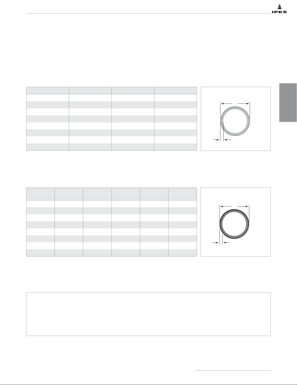
PIPE DIMENSIONS
Dimensional data in this manual is subject to change without notice.
The following dimensions are given as a guide to engineers and installers. They are subject to change and to manufacturing
tolerances. Prior to utilizing these dimensions in a CAD system, or in the preparation of prefabricated pipe sections, consult
IPEX to verify the appropriate tolerances and dimensions are current.
Flame retardant
Pipe Schedule 40, 10ft Standard Lengths
Pipe Schedule 40 & 80, 20ft Standard Lengths
Non-flame retardant
(Black)
Fitting End Abbreviations
EJ - Enfield Joint FST - Female Straight Thread
MPT - Male Pipe Thread MST - Male Straight Thread
FPT - Female Pipe Thread LN - Loose Nut (mates with EJ male thread)
(Green / Blue)
SECTION TWO: DIMENSIONS
DIMENSIONS
9
IPEX Acid Waste Piping Systems
Cat. No. Size (in) t min. A (in)
W001 / W001P 1-1/2 0.145 1.900
W002 / W002P 2 0.154 2.375
W003 / W003P 3 0.216 3.500
W004 / W004P 4 0.237 4.500
W006 6 0.280 6.625
W008 8 0.322 8.625
W010 10 0.365 10.750
W012 12 0.406 12.750
Sch. 40
Cat. No.
Sch. 80
Cat. No.
Size (in)
t min.
(Sch 40)
t min.
(Sch 80)
A (in)
WB01 WB1106 1-1/2 0.145 0.200 1.900
WB02 WB1107 2 0.154 0.218 2.375
WB03 WB1108 3 0.216 0.300 3.500
WB04 WB1109 4 0.237 0.337 4.500
WB06 WB1110 6 0.280 0.432 6.625
WB08 WB1111 8 0.322 0.500 8.625
WB10 WB1112 10 0.365 0.593 10.750
WB12 WB1113 12 0.406 0.687 12.750
t
A
A
t
Page 17
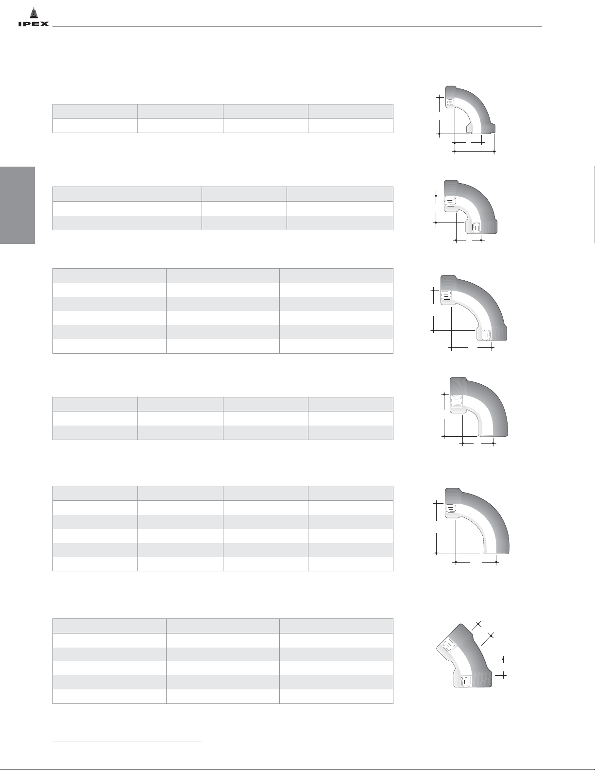
90º Sweep Socket x Spigot
1/8 Bend Socket x Socket
90º Sweep Socket x Loose Nut
ENFIELD FITTING DIMENSIONS
1/4 Bend Socket x Socket
90º Sweep Socket x Socket
1/4 Bend Socket x Spigot
Cat. No. Size (in) A (in) B (in)
L291A 1-1/2 1-3/4 3
Cat. No. Size (in) E (in)
L181 1-1/2 1-9/16
L182 2 2-1/8
Cat. No. Size (in) E (in)
L171 1-1/2 2-3/4
L172 2 3-3/8
L173 3 4-1/8
L174 4 5-1/4
L176 6 7
Cat. No. Size (in) E (in) H (in)
L291 1-1/2 3 1-3/4
L292 2 3-3/8 2-1/8
Cat. No. Size (in) D (in) E (in)
L281 1-1/2 2-7/8 4-1/8
L282 2 3-7/16 4-3/4
L283 3 4-3/8 6
L284 4 5-5/16 7
L286 6 6-13/16 9-1/2
Cat. No. Size(in) D(in)
L191 1-1/2 1-3/8
L192 2 2
L193 3 2-5/8
L194 4 2-7/8
L196 6 2-1/4
IPEX Acid Waste Piping Systems
10
DIMENSIONS
B
A
2 1/8"
E
E
E
E
E
H
E
D
D
D
Page 18
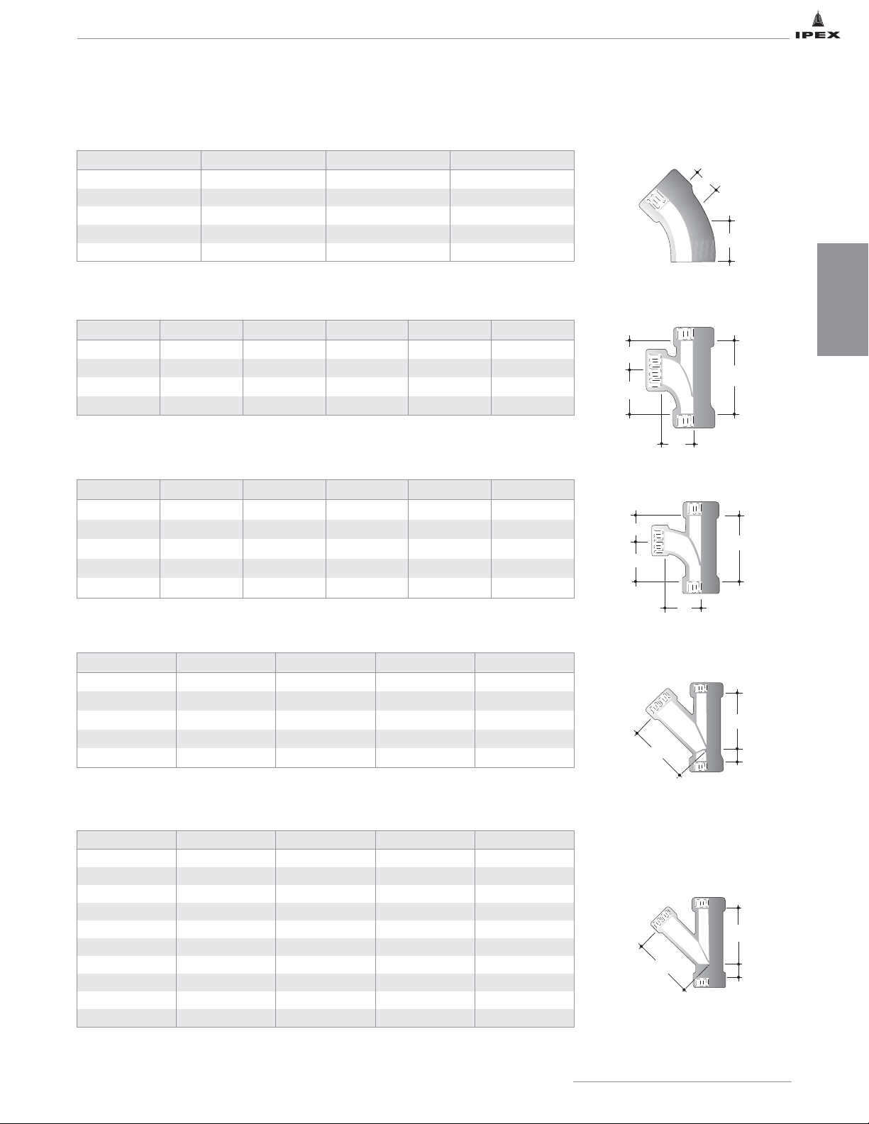
ENFIELD FITTING DIMENSIONS
1/8 Bend Socket x Spigot
Sanitary Tee Socket
Cat. No. Size (in) D (in) F (in)
L211 1-1/2 1-1/8 2-1/4
L212 2 1-3/8 3-1/16
L213 3 2 3-5/8
L214 4 1-15/16 3-13/16
L216 6 2-5/16 4-13/16
Cat. No. Size (in) A (in) B (in) C (in) D (in)
L201 1-1/2 2-1/2 2-1/2 1-3/4 4-1/4
L202 2 2-1/4 2-13/16 2 4-13/16
L203 3 2-15/16 3-1/8 1-3/4 4-7/8
L204 4 4 4 2 6
IPEX Acid Waste Piping Systems
11
DIMENSIONS
Reducing Tee Socket
Cat. No. Size (in) A (in) B (in) C (in) D (in)
L2021 2 x 2 x 1-1/2 2-1/4 2-3/4 2-1/8 4-7/8
L2031 3 x 3 x 1-1/2 5-15/16 3-1/8 1-3/4 4-7/8
L2032 3 x 3 x 2 4-11/16 3-1/8 1-3/4 4-7/8
L2042 4 x 4 x 2 3-1/4 2-1/4 1-1/8 3-1/4
L2043 4 x 4 x 3 6-1/2 4 2 6
45º Wye Socket
Cat. No. Size (in) A (in) B (in) C (in)
L371 1-1/2 3-3/16 1-1/16 3-1/4
L372 2 3-5/16 1-3/8 3-5/16
L373 3 5-1/4 1-3/4 5-1/16
L374 4 8-7/16 1-3/4 7-7/16
L376 6 8-7/16 1-3/4 8-1/2
Reducing Wye Socket
Cat. No. Size (in) A (in) B (in) C (in)
L3721 2 x 2 x 1-1/2 3-9/16 7/8 3-5/8
L3731 3 x 3 x1-1/2 5-7/8 3/4 7-1/4
L3732 3 x 3 x 2 5-7/8 3/4 6
L3741 4 x 4 x 1-1/2 6-3/8 1/2 7-3/4
L3742 4 x 4 x 2 6-3/8 1/2 6-1/2
L3743 4 x 4 x 3 8-7/16 1-3/4 9-15/16
L3761 6 x 6 x 1-1/2 8-1/2 1-3/4 12-3/4
L3762 6 x 6 x 2 8-1/2 1-3/4 11-1/2
L3763 6 x 6 x 3 8-1/2 1-3/4 11-1/2
L3764 6 x 6 x 4 8-1/2 1-3/4 9
D
F
C
D
B
A
C
D
B
A
A
C
C
B
A
B
Page 19
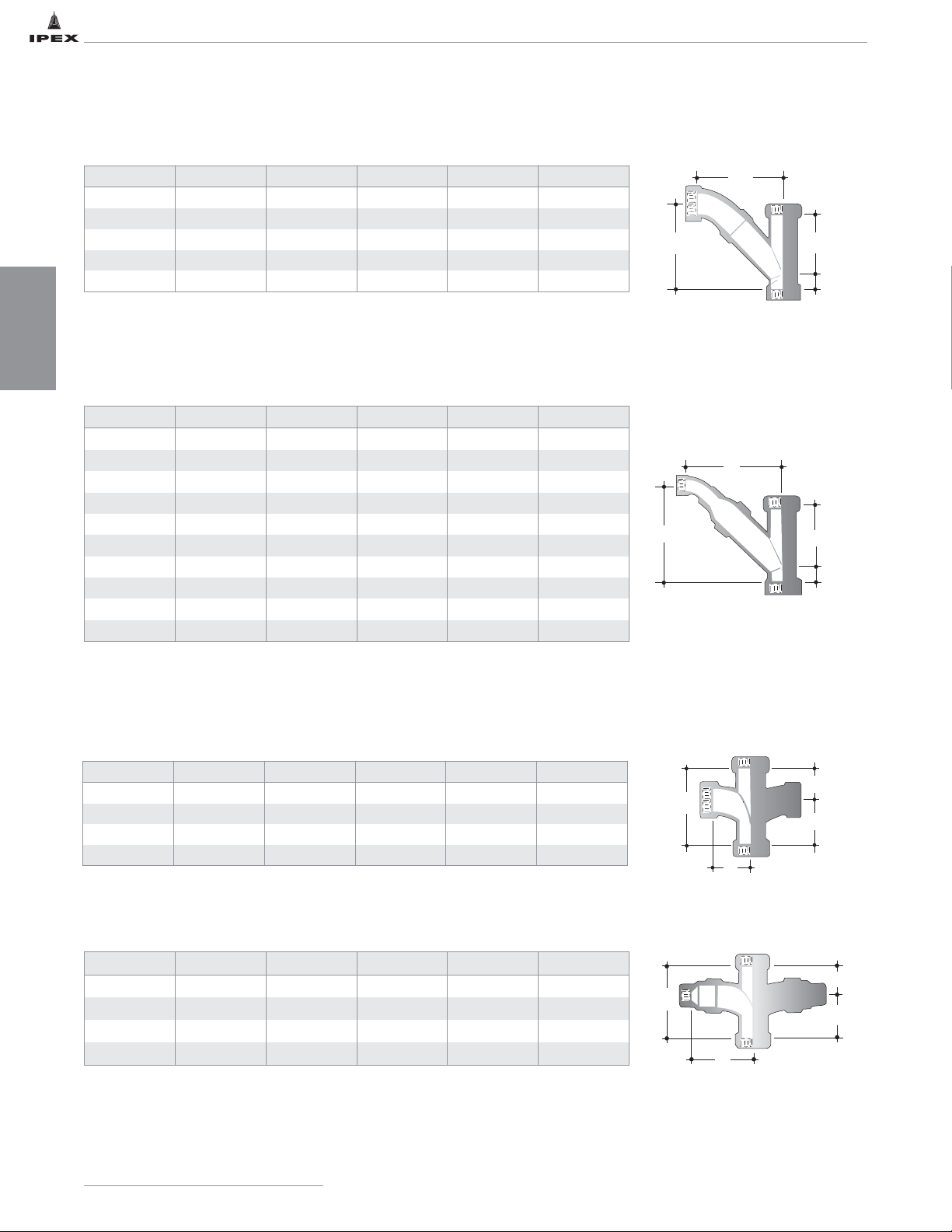
Combination Wye & 1/8 Bend Socket Bend supplied loose
Red. Combination Wye & 1/8 Bend Socket Bend supplied loose
Double Sanitary Tee Socket
ENFIELD FITTING DIMENSIONS
Cat. No. Size (in) A (in) B (in) C (in) D (in)
L3715 1-1/2 3-3/16 5 4-15/16 1-1/16
L3725 2 3-5/16 5-7/8 5-7/8 3/8
L3735 3 5-1/16 8-1/8 7-7/16 5/16
L3745 4 8-7/16 9-7/8 9-11/16 1-3/4
L3755 6 8-7/16 11-13/16 11-1/4 1-3/4
Cat. No. Size (in) A (in) B (in) C (in) D (in)
L351 1-1/2 3-11/16 2-1/2 3-11/16 6-3/16
L352 2 2-7/16 1-1/4 2-7/16 3-11/16
L353 3 3-1/4 1-5/8 3-1/4 4-7/8
L354 4 4 2-1/8 4 6-1/8
Cat No Size (in) A (in) B (in) C (in) D (in)
L37251 2 x 1-1/2 3-9/16 5-1/4 5 7/8
L37351 3 x 1-1/2 5-7/8 7-13/16 7-7/16 3/4
L37352 3 x 2 5-7/8 7-13/16 7-3/16 3/4
L37451 4 x 1-1/2 6-3/8 8-3/16 7-9/16 1/2
L37452 4 x 2 6-3/8 8-1/8 7-1/4 1/2
L37453 4 x 3 8-7/16 11-9/16 11-5/16 1-3/4
L37651 6 x 1-1/2 8-1/2 12-15/16 12-1/16 1-3/4
L37652 6 x 2 8-1/2 11-11/16 12-1/16 1-3/4
L37653 6 x 3 8-1/2 12-11/16 12-7/16 1-3/4
L37654 6 x 4 8-1/2 11 10-13/16 1-3/4
IPEX Acid Waste Piping Systems
12
DIMENSIONS
Reducing Double Sanitary Tee Socket
Cat. No. Size (in) A (in) B (in) C (in) D (in)
L3521 2 x 1-1/2 3-11/16 2-7/16 1-1/4 3-11/16
L3531 3 x 1-1/2 5 3-1/4 1-5/8 4-7/8
L3542 4 x 2 3-1/4 2-3/16 1-1/16 3-1/4
L3543 4 x 3 6-1/2 4 2-1/8 6-1/8
B
C
B
C
A
D
A
D
B
D
A
C
C
D
B
A
Page 20
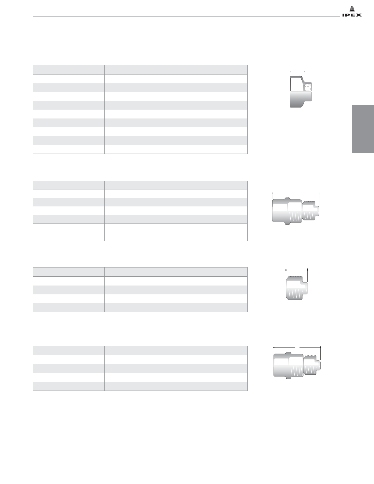
ENFIELD FITTING DIMENSIONS
IPEX Acid Waste Piping Systems
13
DIMENSIONS
Reducing Bushing Spigot x Socket
Cleanout Disassembled Length
Cat. No. Size (in) A (in)
L3912 2 x 1-1/2 1-1/4
L3913 3 x 1-1/2 1-3/4
L3923 3 x 2 1-3/4
L3914 4 x 1-1/2 3-3/4
L3924 4 x 2 2-1/2
L3934 4 x 3 2-1/2
L3916 6 x 1-1/2 2-1/2
L3936 6 x 3 4-7/8
L3946 6 x 4 3
Cat. No. Size (in) A (in)
L241 1-1/2 5-1/4
L242 2 6
L243 3 5-7/8
L244 4 7
L246 6
11-5/8 (disassembled)
10 (assembled)
Cleanout Plug Male Thread
Cleanout w/ Brass Plug Disassembled Length
Cat. No. Size (in) A (in)
L241A 1-1/2 2-1/4
L242A 2 2-5/16
L243A 3 2-5/16
L244A 4 3
Cat. No. Size (in) A (in)
L2401 1-1/2 4
L2402 2 4-1/2
L2403 3 4-1/2
L2404 4 5
A
A
A
A
Page 21
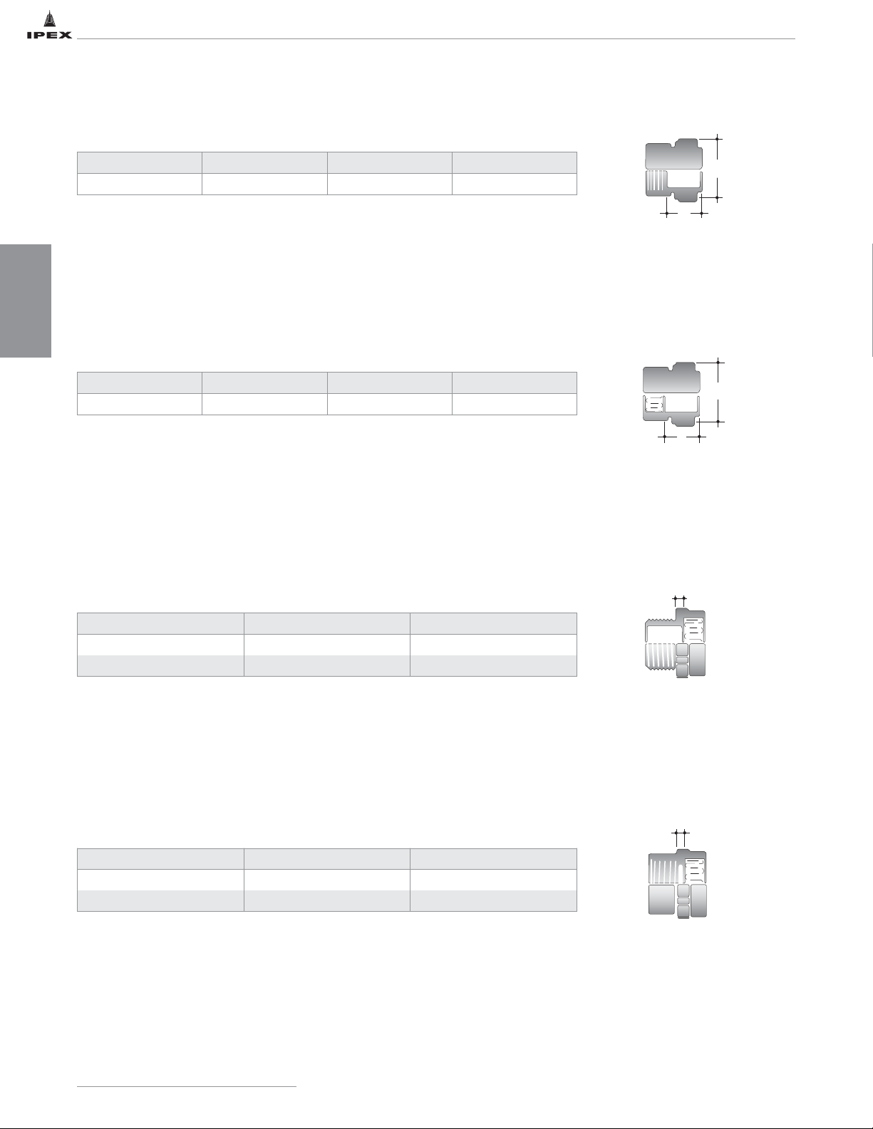
ENFIELD FITTING DIMENSIONS
Adapter Socket x Loose Nut
Male Adapter Male Thread x Socket
Female Adapter Female Thread x Socket
Adapter Female Thread x Loose Nut
Cat. No. Size (in) A (in) B (in)
L101 1-1/2 1-1/2 2-11/16
Cat. No. Size (in) A (in) B (in)
L111 1-1/2 1-1/2 2-7/16
Cat. No. Size (in) A (in)
L141 1-1/2 5/16
L142 2 5/16
Cat. No. Size (in) A (in)
L151 1-1/2 3/8
L152 2 3/8
IPEX Acid Waste Piping Systems
14
DIMENSIONS
B
A
B
A
A
A
Page 22
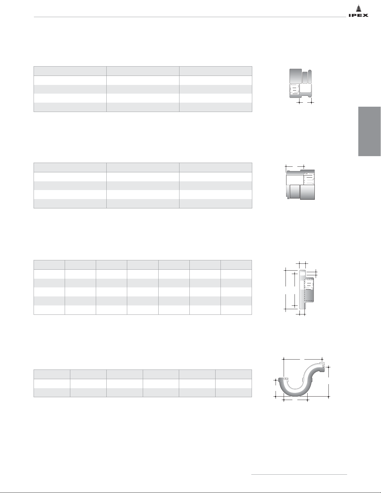
ENFIELD FITTING DIMENSIONS
Cast Iron Adapter Spigot x Socket
Flange Socket,ANSI 150 bolt pattern
Note: Backing plates, bolts and gaskets should be ordered as separate items.
Suitable gasket material must be selected.
Glass Adapter Socket x Bead
P Trap 2-piece, Socket x Socket
Cat. No. Size (in) A (in)
L451 1-1/2 1-1/8
L452 2 1-5/16
L453 3 1-9/16
L454 4 1-5/8
Cat. No. Size (in) A (in)
L461 1-1/2 1-1/4
L462 2 1-5/8
L463 3 2-1/8
L464 4 2-1/8
Cat. No. Size (in) A (in) B (in) C (in) D (in) E (in)
L361 1-1/2 3-7/8 5-1/8 5/8 13/16 9/16
L362 2 4-3/4 6-3/16 11/16 15/16 11/16
L363 3 6 7-3/8 15/16 1-1/8 11/16
L364 4 7-7/16 8-15/16 1-1/16 1-3/8 11/16
L366 6 9-1/2 10-15/16 1-1/16 13/16 13/16
Cat. No. Size (in) A (in) B (in) C (in) D (in)
L1021 1-1/2 5 5-5/16 2-5/16 3-1/4
L1022 2 7-1/8 6-7/16 3-1/16 5
IPEX Acid Waste Piping Systems
15
DIMENSIONS
A
A
C
E
B
A
D
A
B
C
D
Page 23
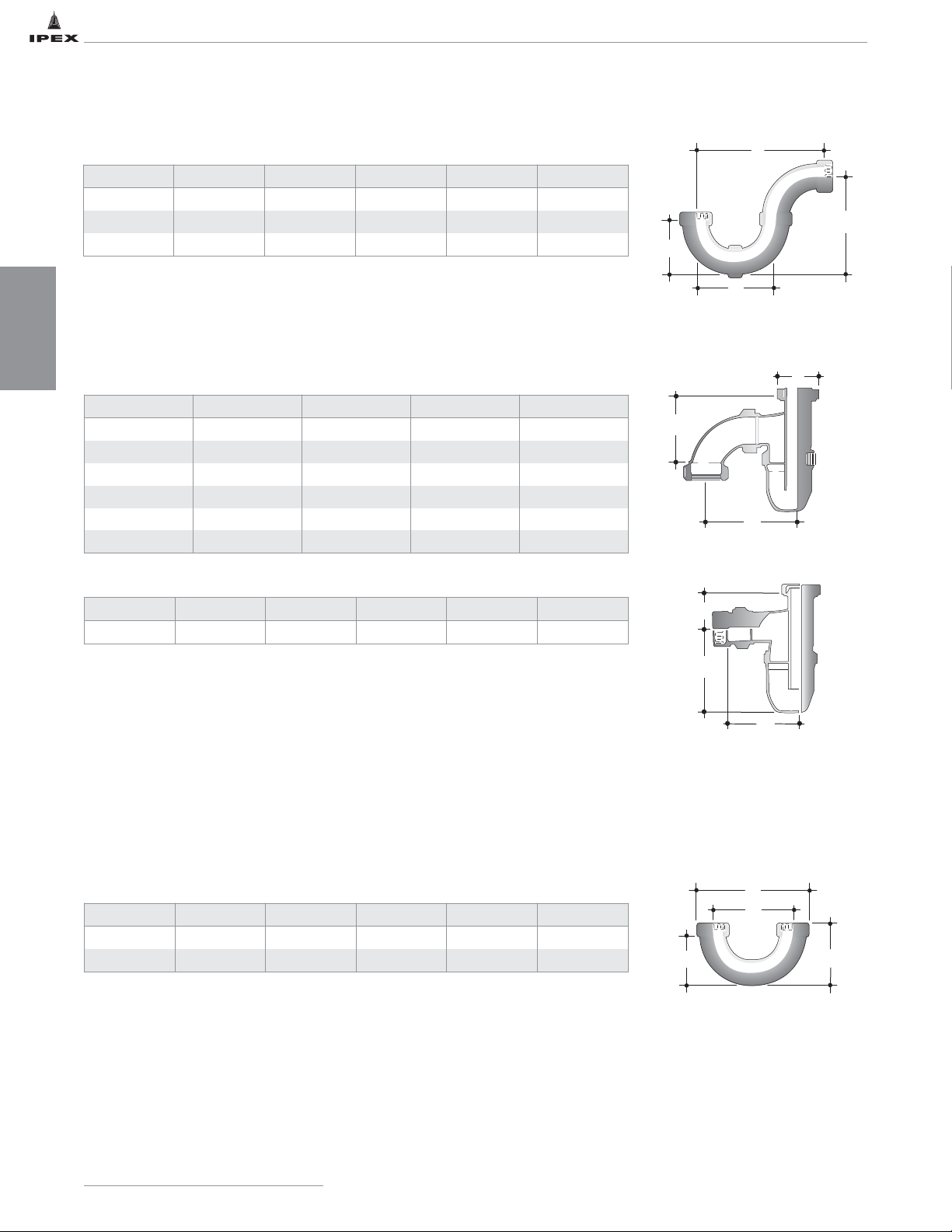
ENFIELD FITTING DIMENSIONS
Note: 3" deep seal Universal Traps have a 1-1/2" loose nut inlet which connects
directly to Enfield cup sinks and sink outlets or can be adapted to other brands by
means of adapters W121 and W131. All universal trap adapters contain nitrile
gaskets. Other special chemical resistance gaskets are available upon request.
Universal Traps
S-type
P-type
P Trap 3-piece, Socket x Socket
Vent Loop / U Bend
Cat. No. Size (in) A (in) B (in) C (in) D (in)
LT13 3 14-1/2 11-7/8 6-1/8 10-1/8
LT14 4 17-9/16 14-1/2 7-9/16 12-1/4
LT16 6 23-5/16 19-13/16 10-1/8 16-1/2
Cat. No. Type Size (in) Outlet Base
L501 P 1-1/2 Socket Solid
L5011 P 1-1/2 FPT Solid
L511* P 1-1/2 Socket Clear
L5111* P 1-1/2 FPT Clear
L5015 S 1-1/2 Socket Solid
L5115* S 1-1/2 Socket Clear
A (in) B (in) C (in) D (in) E (in) F (in)
2-3/16 3-7/8 5-1/2 4-5/16 2 5-1/4
Cat. No. Size (in) E (in) F (in) L (in) M (in)
L1011 1-1/2 2-5/16 3-1/4 5-5/8 3-1/16
L1012 2 3-1/16 5 7-13/16 4-1/16
IPEX Acid Waste Piping Systems
16
DIMENSIONS
* Clear base made from TPX (Methylpentene Copolymer)
A
B
C
D
A
B
C
E
F
D
L
F
E
M
Page 24
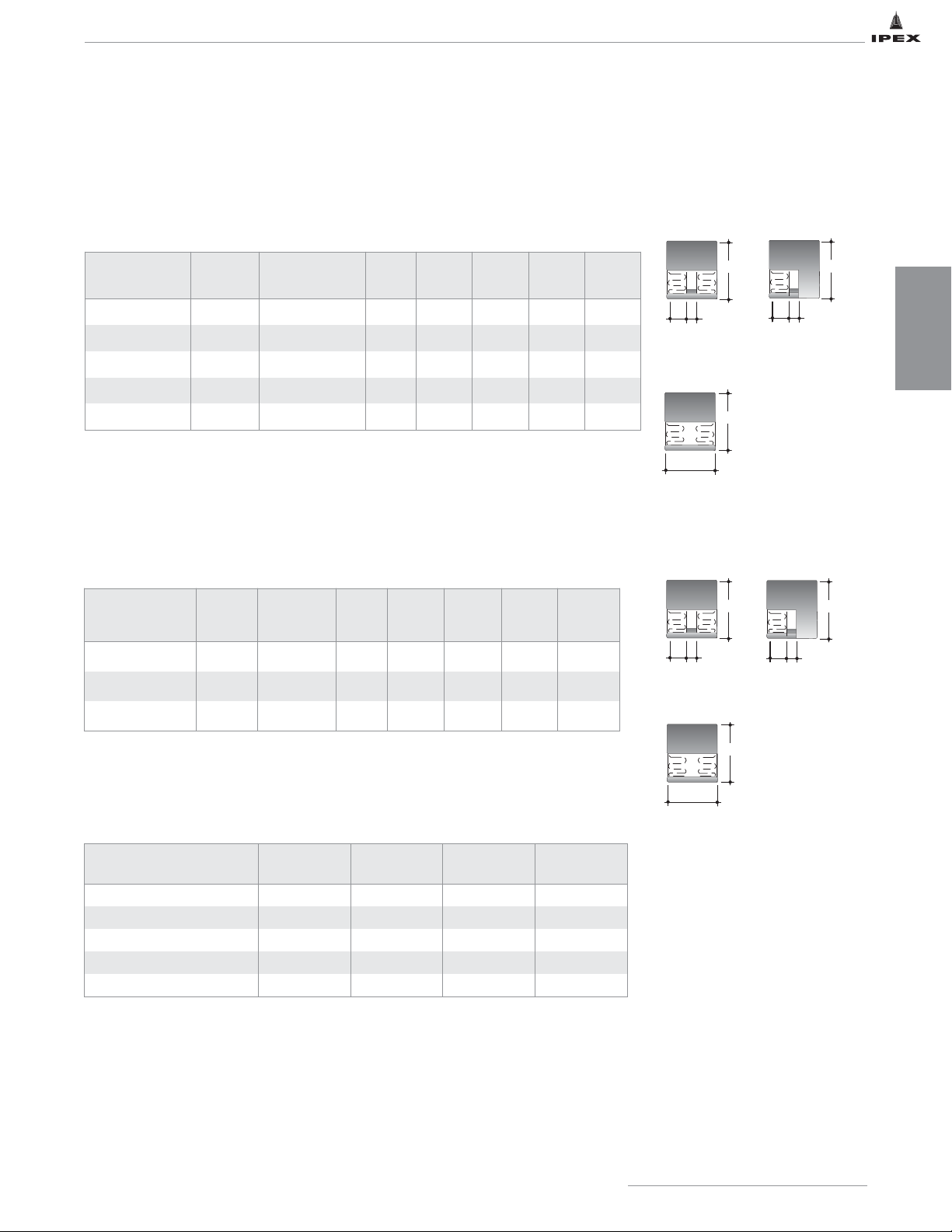
ENFIELD FITTING DIMENSIONS
Large Diameter Coupling & Fabricated Cap Socket
Suffix ‘B’ indicates Black Non-Flame Retardant PP
‘B’ is the fitting OD dimension
‘C’ is the socket depth
Coupling & Fabricated Cap Socket
Coupling Cap
Coupling
Cap
B
2 x C + A
Suffix ‘B’ indicates Black Non-Flame Retardant PP
Note: Enfield fabricated fittings are custom made from pipe, couplings and molded fittings. Due to manufacturing
constraints, some fittings may not be exactly symmetrical or appear as sketched. The dimensions provided are
approximate and should not be used to create precise layouts.
Repair
Coupling
Repair
Coupling
Coupling
Cat. No.
Cap
Cat. No.
Repair Coupling
Cat. No.
Size
(in)
A
(in)
B
(in)
C
(in)
Cap
L161 L641 L161R 1-1/2 5/16 2-7/16 3/4 1-3/4
L162 / L162B L642 L162R 2 5/16 2-13/16 1 1-15/16
L163 / L163B L643 L163R 3 1/2 4 1-3/8 1/2
L164 / L164B L644 L164R 4 1/2 5-1/16 1-1/2 1/2
L166 / L166B L646 L166R 6 1/2 7-3/16 2 2-1/2
Coupling
Cat. No.
Cap
Cat. No.
Repair
Coupling
Cat. No.
Size
(in)
A
(in)
B
(in)
C
(in)
Cap
L168 / L168B L648 L168R 8 1/2 9-1/4 2-1/4 2-3/4
L1610 / L1610B L6410 -- 10 3/16 11-1/2 2-5/8 2-3/4
L1612 / L1612B L6412 -- 12 3/16 13-5/8 2-3/4 2-7/8
Fabricated Repair Couplings Socket
Coupling
Cat. No.
Size (in) A (in) B (in) C (in)
L162R 2 1/4 2-13/16 1
L163R 3 3/8 4 1-3/8
L164R 4 7/16 5-1/16 1-1/2
L166R 6 1/2 7-3/16 2
L168R 8 1/2 9-3/8 2-1/4
IPEX Acid Waste Piping Systems
17
DIMENSIONS
B
C
A
B
2 x C + A
B
C
A
B
B
Page 25
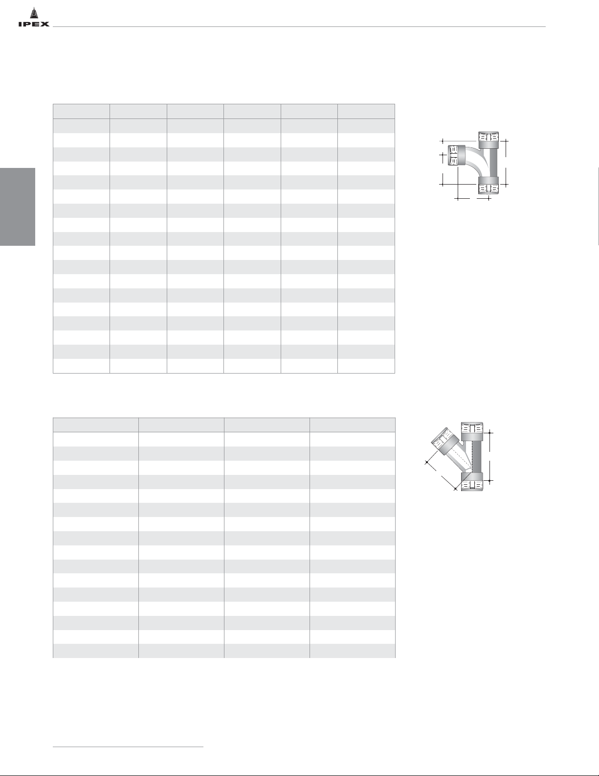
ENFIELD FITTING DIMENSIONS
Fabricated 45° Wye Socket
Cat. No. Size (in) A (in) B (in)
L3782 8 x 2 9-15/16 12-3/16
L3783 8 x 3 11-3/8 13-11/16
L3784 8 x 4 11-13/16 15-3/16
L3786 8 x 6 12-15/16 18-3/16
L378 8 x 8 14-1/2 20-11/16
L37103 10 x 3 12-7/8 13-7/8
L37104 10 x 4 13-5/16 15-3/8
L37106 10 x 6 14-7/16 18-3/8
L37108 10 x 8 16 21-1/8
L3710 10 x 10 17-3/4 24-3/8
L37123 12 x 3 14-1/4 13-5/8
L37124 12 x 4 14-11/16 15-1/8
L37126 12 x 6 15-13/16 18-1/8
L37128 12 x 8 17-7/16 20-7/8
L371210 12 x 10 19-3/16 24-1/8
L3712 12 x 12 20-1/16 26-5/8
IPEX Acid Waste Piping Systems
18
DIMENSIONS
Fabricated Sanitary Tee Socket
Cat. No. Size (in) A (in) B (in) C (in) D (in)
L2062 6 x 2 10-7/16 7-3/8 3-5/8 11
L2063 6 x 3 11-3/16 8-1/8 3-7/8 12
L2064 6 x 4 11-1/2 8-7/18 4-1/8 13
L206 6 x 6 12-1/2 11-7/16 5-13/16 17-1/4
L2083 8 x 3 12-13/16 9 4-11/16 13-11/16
L2084 8 x 4 12-1/2 9-15/16 5-1/4 15-3/16
L2086 8 x 6 13-1/2 11-7/16 6-5/16 18-3/16
L208 8 x 8 14-3/8 13-9/16 7-1/8 20-11/16
L20103 10 x 3 13-1/4 9-1/16 4-13/16 13-7/8
L20104 10 x 4 13-9/16 10 5-5/16 15-3/8
L20106 10 x 6 14-9/16 11-15/16 6-3/8 18-3/8
L20108 10 x 8 15-7/16 13-5/8 7-1/4 20-7/8
L2010 10 x 10 16-1/16 15-13/16 8-9/16 24-3/8
L20124 12 x 4 14-9/16 9-15/16 5-1/4 15-1/8
L20126 12 x 6 15-9/16 11-7/8 6-5/16 18-1/8
L20128 12 x 8 16-7/16 13-5/8 7-1/4 20-7/8
L201210 12 x 10 17-1/16 15-11/16 8-7/16 24-1/8
L2012 12 x 12 17-3/4 17-3/8 9-1/4 26-5/8
C
B
A
D
B
A
Page 26
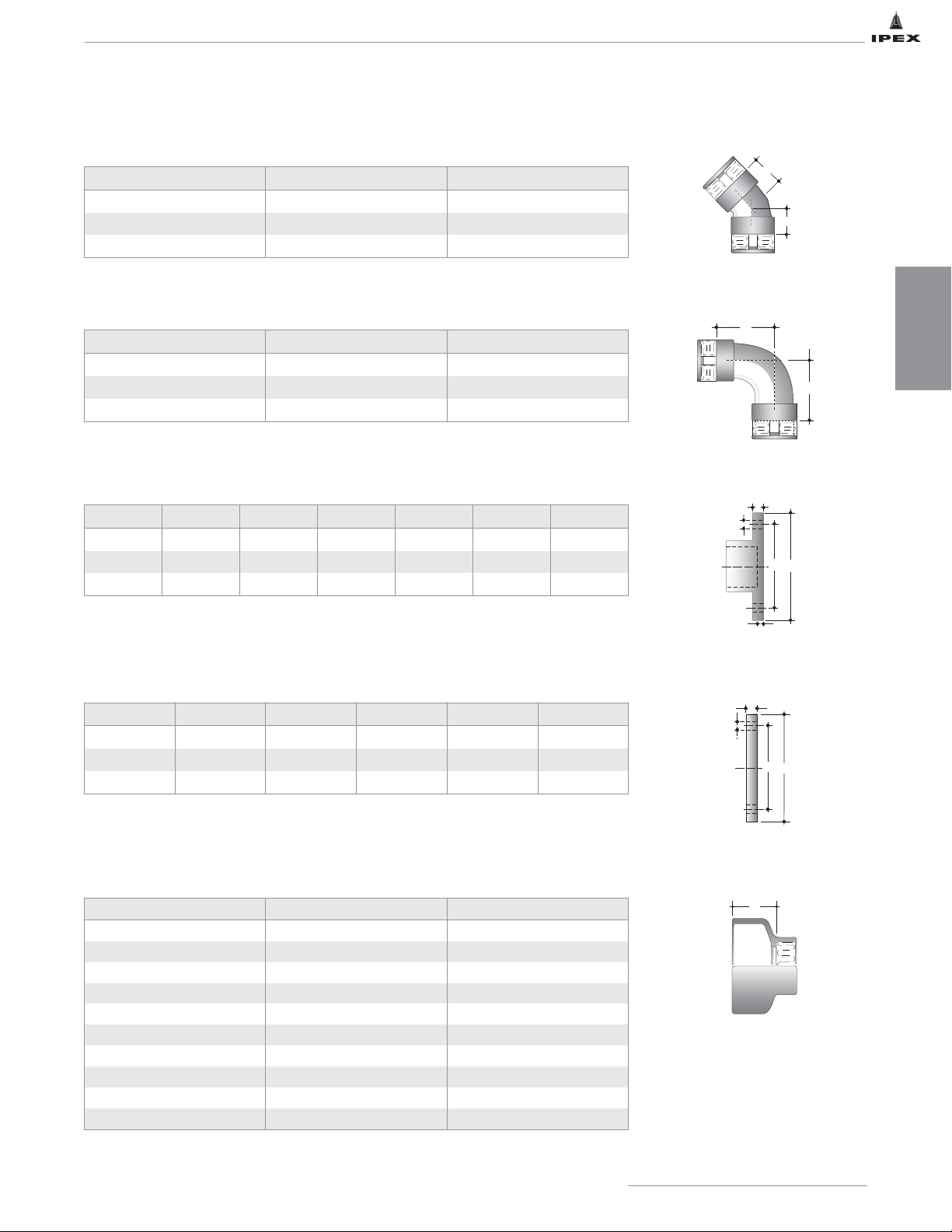
ENFIELD FITTING DIMENSIONS
Fabricated Socket Flange Socket, ANSI 150 bolt pattern
Fabricated Blind Flange
Fabricated Reducing Bushing Spigot x Socket
Note: Backing plates, bolts and gaskets should be ordered as separate items.
See Standard Bolt Dimensions at end of section. A suitable gasket material must be selected.
Note: Backing plates, bolts and gaskets should be ordered as separate items.
See Standard Bolt Dimensions at end of section. A suitable gasket material must be selected.
Fabricated 1/8 Bend Socket x Socket
Fabricated 1/4 Bend Socket x Socket
Cat. No. Size (in) A (in)
L198 8 6-7/8
L1910 10 7
L1912 12 7-5/16
Cat. No. Size (in) A (in)
L188 8 12-3/4
L1810 10 13-9/16
L1812 12 14-5/8
Cat. No. Size (in) d1 (in) d2 (in) E (in) F (in) G (in)
L368 8 11-3/4 13-1/2 3/4 7/8 1/4
L3610 10 14-1/4 16 3/4 1 1/4
L3612 12 17 19 3/4 1 1/4
Cat. No. Size (in) d1 (in) d2 (in) G (in) F (in)
L3688 8 11-3/4 13-1/2 3/4 7/8
L361010 10 14-1/4 16 3/4 1
L361212 12 17 19 3/4 1
Cat. No. Size (in) A (in)
L3938 8 x 3 4-3/4
L3948 8 x 4 2-3/4
L3968 8 x 6 2-3/4
L39410 10 x 4 6-3/4
L39610 10 x 6 6-3/4
L39810 10 x 8 4
L39412 12 x 4 10-15/16
L39612 12 x 6 10-13/16
L39812 12 x 8 8
L391012 12 x 10 4
IPEX Acid Waste Piping Systems
19
DIMENSIONS
A
A
A
A
E
F
d1
d2
G
G
F
d1
d2
A
Page 27
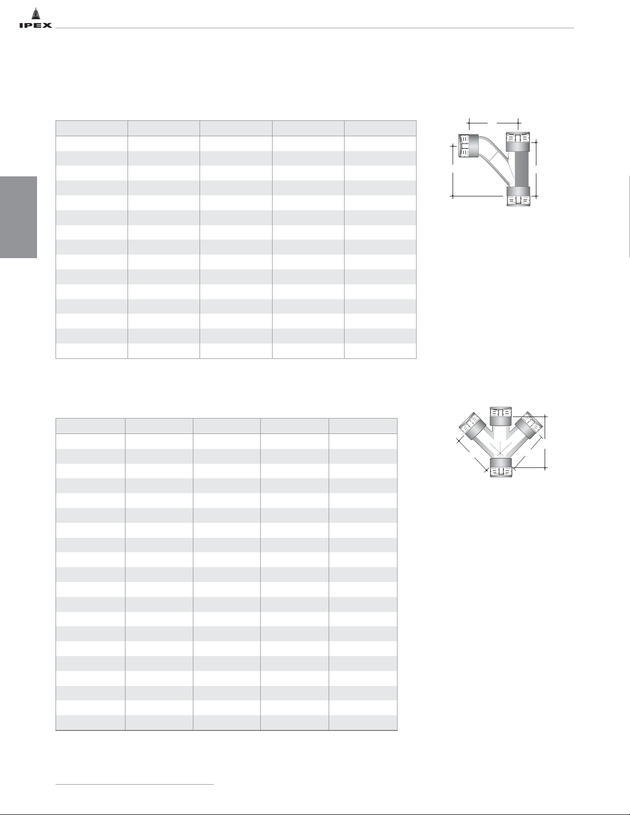
Cat. No. Size (in) A (in) B (in) C (in)
L37853 8 x 3 11-1/8 13-11/16 14-5/16
L37854 8 x 4 12-3/4 15-3/16 15-3/8
L37856 8 x 6 16-1/8 18-3/16 17-11/16
L3785 8 x 8 19-3/16 20-11/16 20-1/16
L371053 10 x 3 11-3/16 13-7/8 15-3/8
L371054 10 x 4 12-7/8 15-3/8 16-7/16
L371056 10 x 6 16-3/16 18-3/8 18-3/4
L371058 10 x 8 19-5/16 20-7/8 21-1/8
L37105 10 x 10 22-7/8 24-3/8 23-1/8
L371253 12 x 3 11-1/16 13-5/8 16-3/8
L371254 12 x 4 12-3/4 15-1/8 17-7/16
L371256 12 x 6 16-1/8 18-1/8 19-3/4
L371258 12 x 8 19-5/16 20-7/8 22-1/8
L3712510 12 x 10 22-13/16 24-1/8 24-1/8
L37125 12 x 12 25-7/8 26-5/8 26-1/4
Fabricated Combination Wye & 1/8 Bend Socket
Cat. No. Size (in)
A1(in) A2(in)
B (in)
L3821 2 x 1-1/2 3-5/8 4-1/4 4-7/16
L382 2 x 2 3-5/16 4-1/2 4-11/16
L3832 3 x 2 6 6-3/4 6-5/8
L383 3 x 3 5-1/16 6-1/4 6-3/8
L3842 4 x 2 6-1/2 6-7/8 6-7/8
L3843 4 x 3 9-15/16 10-15/16 10-3/16
L348 4 x 4 7-7/16 8-7/16 10-3/16
L3864 6 x 4 3-1/4 10 11-1/2
L368 6 x 6 11-1/2 11-1/2 17-1/4
L886 8 x 6 12-15/16 12-15/16 18-3/16
L388 8 x 8 14-1/2 14-7/16 20-11/16
L38104 10 x 4 13-5/16 13-5/16 15-3/8
L38106 10 x 6 14-7/16 14-7/16 18-3/8
L38108 10 x 8 16 16 21-1/8
L3810 10 x 10 17-3/4 17-3/4 24-3/4
L38124 12 x 4 14-11/16 14-11/16 15-1/8
L38126 12 x 6 15-13/16 15-13/16 18-1/8
L38128 12 x 8 17-7/16 17-7/16 20-7/8
L381210 12 x 10 19-3/16 19-3/16 24-1/8
L3812 12 x 12 20-1/8 20-1/8 26-11/16
Fabricated Double 45º Wye Socket
IPEX Acid Waste Piping Systems
20
ENFIELD FITTING DIMENSIONS
DIMENSIONS
C
A
B
B
A1
A2
Page 28
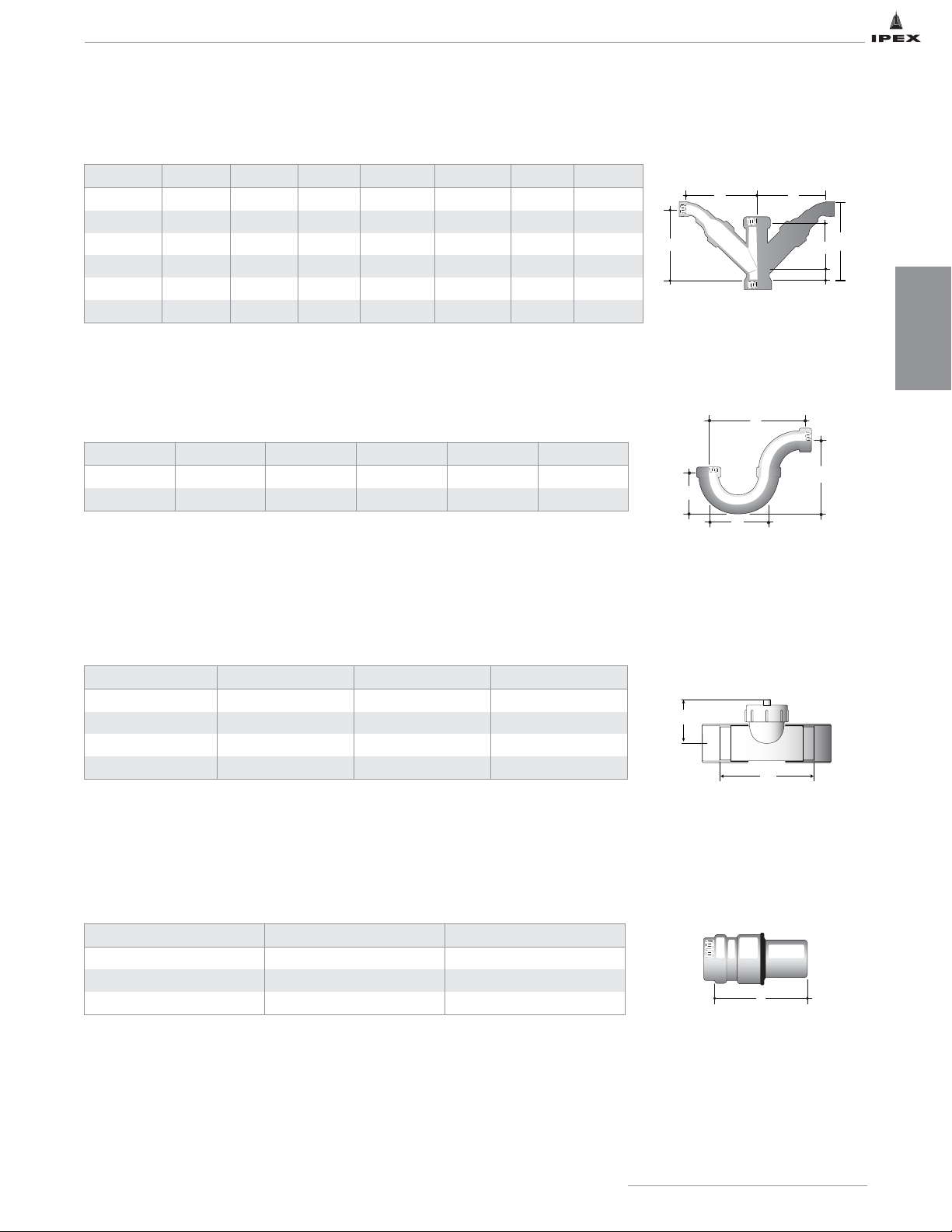
Fabricated Double Combination Wye & 1/8 Bend Socket
Fabricated P Trap Socket
Fabricated Cleanout Tee Socket
Fabricated Expansion Joint
Cat No Size (in) A (in) B (in)
L901 1-1/2 12 4-11/16
L902 2 9-1/2 4-11/16
L903 3 9-7/8 4-7/8
L904 4 9-15/16 5-5/8
Cat No Size (in) A (in)
B1(in) B2(in) C1(in) C2(in)
D (in)
L3825 2 x 2 3-5/16 5-7/8 6-13/16 6-1/8 6-1/8 1-3/8
L38352 3 x 2 5-7/8 7-13/16 7-9/16 7-1/8 7-1/8 3/4
L3835 3 x 3 5-1/16 8-1/8 9 7-3/4 7-3/4 1-5/16
L38452 4 x 2 6-3/8 8-1/2 8-5/16 7 7-1/8 1/2
L3845 4 x 4 8-7/16 9-7/8 10-1/8 9-9/16 9-9/16 1-3/4
L3865 6 x 6 12-1/8 11-5/8 11-5/8 14-1/2 14-1/2 5-1/8
Cat No Size (in) A (in) B (in) C (in) D (in)
LT18 8 34-1/2 28-1/2 17 22-3/4
LT110 10 38 32 19 24-3/4
Cat No Size(in) A(in)
L803 3 13-1/2
L804 4 13-5/8
L806 6 18
IPEX Acid Waste Piping Systems
21
ENFIELD FITTING DIMENSIONS
DIMENSIONS
Note: Enfield fabricated fittings are custom made from pipe, couplings and molded
fittings. Due to manufacturing constraints, some fittings may not be exactly
symmetrical or appear as sketched. The dimensions provided are approximate.
B1 B2
C
C1
A
C
D
2
A
D
B
B
A
A
Page 29
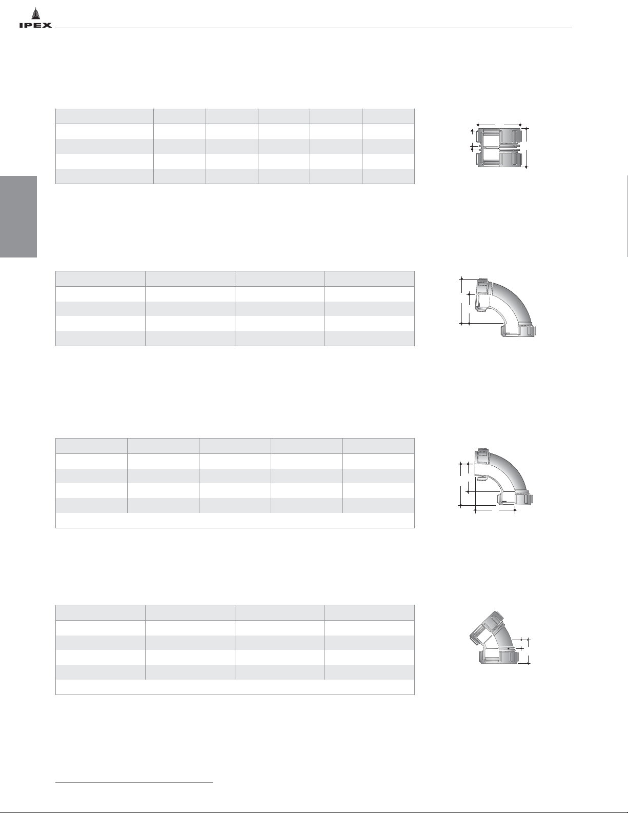
LABLINE AND PLENUMLINE FITTING DIMENSIONS
Coupling
1/4 Bend
Loose Nut 1/4 Bend MJ X LN
1/8 Bend
Cat No Size (in) B (in) D (in) L (in) Z (in)
W161 / W161P 1-1/2 3/4 2-7/16 2-3/16 1/8
W162 / W162P 2 1-3/32 3-1/16 2-1/2 1/8
W163 / W163P 3 1-3/4 4-29/32 4-1/4 1/4
W164 / W164P 4 2-1/4 6 5-1/2 1/4
Cat. No. Size (in) E (in) L (in)
W181 / W181P 1-1/2 1-11/16 2-15/16
W182 / W182P 2 2-1/2 4-1/8
W183 / W183P 3 3-3/8 5-5/8
W184 / W184P 4 3-15/16 7-3/16
Cat. No. Size (in) G (in) H (in) L (in)
W291 / W291P 1-1/2 2-9/16 2-1/8 3-1/8
W292 / W292P 2 3-11/16 2-1/2 3-11/16
W293 / W293P 3 5-3/8 3-7/16 4-15/16
W294 / W294P 4 6-9/16 4-1/8 6-7/16
Use to convert universal traps to “S” type making up tubular traps.
Cat. No. Size (in) E (in) L (in)
W191 / W191P 1-1/2 5/8 1-9/16
W192 / W192P 2 5/8 1-7/8
W193 / W193P 3 2 3-1/2
W194 / W194P 4 1-7/8 4
Combined with loose nut, 1/8 bend provides a useful offset.
IPEX Acid Waste Piping Systems
22
DIMENSIONS
D
B
Z
L
E
L
H
L
G
E
L
Page 30
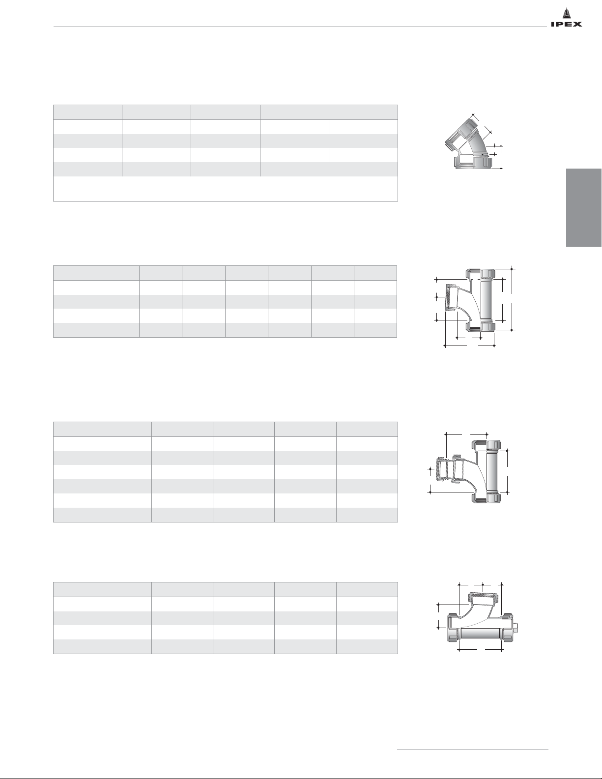
Sanitary Tee
Reducing Sanitary Tee
Cleanout Tee
LABLINE AND PLENUMLINE FITTING DIMENSIONS
Loose Nut 1/8 Bend MJ X LN
Cat. No. Size (in) G (in) H (in) L (in)
W211 / W211P 1-1/2 1-3/4 5/8 1-3/8
W212 / W212P 2 1-3/4 5/8 1-11/16
W213 / W213P 3 4-1/8 2 3-1/2
W214 / W214P 4 4-1/2 1-3/4 4
When used with W151 female adapter and screwed directly to sink, outlet provides a
compact assembly for turning drainline back to wall.
Cat. No. Size (in) G (in) H (in) E (in) L (in) M (in)
W201 / W201P 1-1/2 2-5/16 1-1/2 3-13/16 6 4-1/4
W202 / W202P 2 2-1/2 2 4-1/2 7 5-5/16
W203 / W203P 3 3-1/4 1-9/16 4-3/4 9 7-13/16
W204 / W204P 4 3-7/8 3 6-7/8 12-1/16 10
Cat. No. Size (in) A (in) B (in) C (in)
W2021 / W2021P 2 x 1-1/2 3-13/16 4-1/16 2-1/2
W2031 / W2031P 3 x 1-1/2 4-3/4 5-1/2 3-1/4
W2032 / W2032P 3 x 2 4-3/4 5-1/2 3-1/4
W2041 4 x 1-1/2 6-7/8 7-11/16 3-7/8
W2042 / W2042P 4 x 2 6-7/8 7-3/8 3-7/8
W2043 / W2043P 4 x 3 6-7/8 6-3/4 3-7/8
Cat. No. Size (in) A (in) B (in) C (in)
W2015 / W2015P 1-1/2 2-5/16 1-1/2 3-13/16
W2025 / W2025P 2 2-1/2 2 4-1/2
W2035 / W2035P 3 3-1/4 1-9/16 4-3/4
W2045 / W2045P 4 3-7/8 3 6-7/8
IPEX Acid Waste Piping Systems
23
DIMENSIONS
G
H
L
H
G
G
M
E
L
B
C
A
A
A
B
C
Page 31
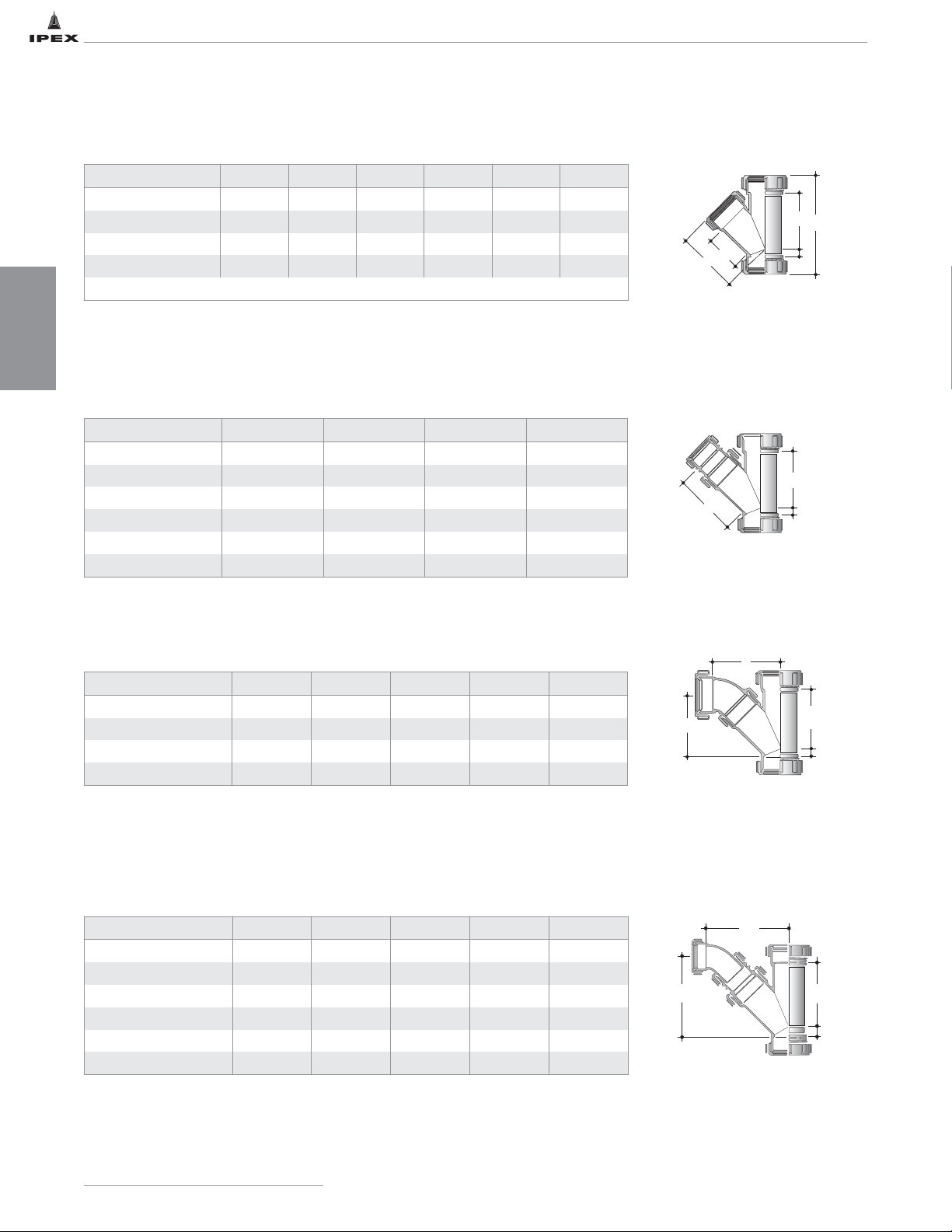
LABLINE AND PLENUMLINE FITTING DIMENSIONS
45º Wye
Reducing 45º Wye
Combination Wye & 1/8 Bend
Red. Combination Wye & 1/8 Bend
Cat. No. Size (in) E (in) F (in) G (in) L (in) M (in)
W371 / W371P 1-1/2 2-1/2 5/16 3-7/16 5-13/16 3-13/16
W372 / W372P 2 3 11/16 3-9/16 6-5/8 4-1/2
W373 / W373P 3 6 1-11/16 7 12-11/16 7-19/32
W374 / W374P 4 7 1-15/16 8-3/8 15-3/4 9-5/16
Combined with loose nut 1/8 bend can provide two parallel inlets to a single pipe.
Cat. No. Size (in) A (in) B (in) C (in)
W3721 / W3721P 2 x 1-1/2 3-9/16 4-9/16 11/16
W3731 / W3731P 3 x 1-1/2 7 8-3/8 1-11/16
W3732 / W3732P 3 x 2 7 8-1/4 1-11/16
W3741 4 x 1-1/2 8-3/8 10-13/16 1-15/16
W3742 / W3742P 4 x 2 8-3/8 10-1/2 1-15/16
W3743 / W3743P 4 x 3 8-3/8 9-7/8 1-15/16
Cat. No. Size (in) A (in) B (in) C (in) D (in)
W3715 / W3715P 1-1/2 3-7/16 3-5/8 3-11/16 5/16
W3725 / W3725P 2 3-9/16 4-1/4 4-1/16 11/16
W3735 / W3735P 3 7 8-1/2 8-13/32 1-11/16
W3745 / W3745P 4 8-3/8 10-1/4 10 1-15/16
Cat. No. Size (in) A (in) B (in) C (in) D (in)
W37251 / W37251P 2 x 1-1/2 3-9/16 6-13/64 4-5/32 11/16
W37351 / W37351P 3 x 1-1/2 7 11-3/8 8-13/32 1-1/16
W37352 / W37352P 3 x 2 7 11-3/8 8-1/2 1-1/16
W37451 4 x 1-1/2 8-3/8 9-1/2 10-3/8 1-11/16
W37452 / W37452P 4 x 2 8-3/8 13-3/8 10 1-11/16
W37453 / W37453P 4 x 3 8-3/8 12-19/32 10 1-11/16
IPEX Acid Waste Piping Systems
24
DIMENSIONS
G
L
E
M
B
F
A
C
B
C
B
C
A
D
A
D
Page 32
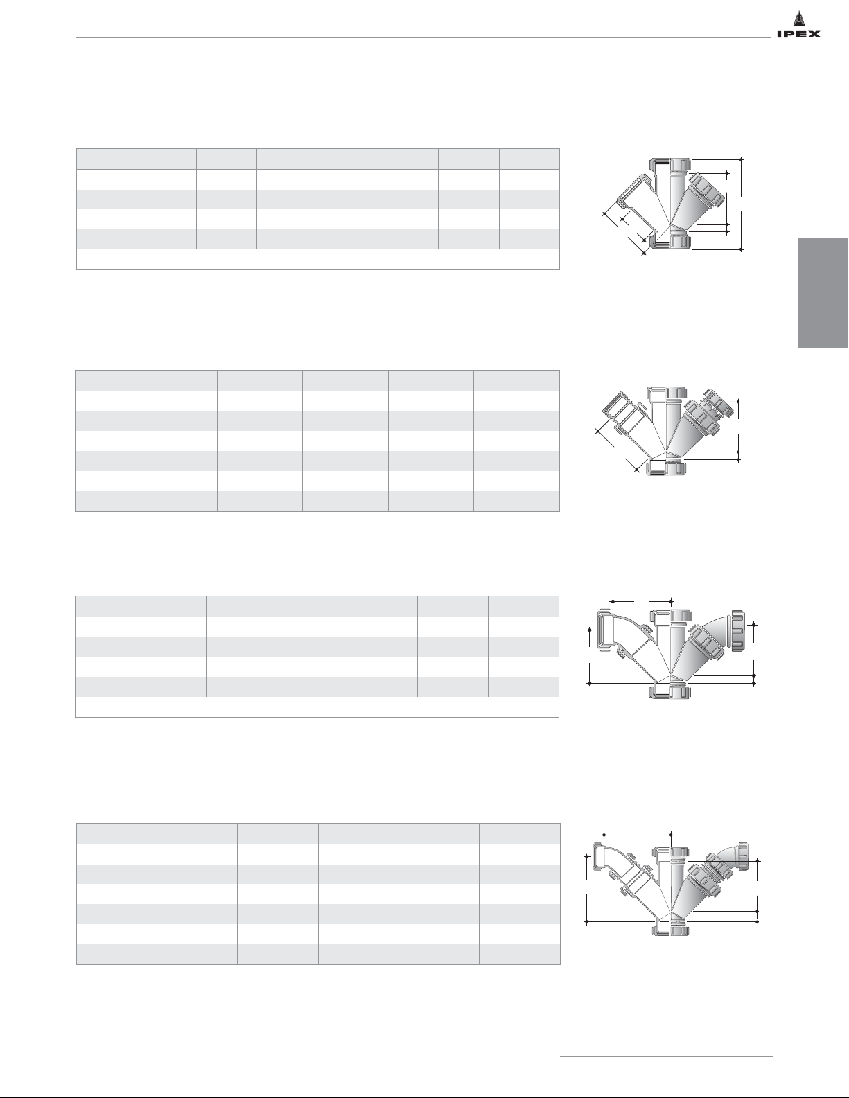
LABLINE AND PLENUMLINE FITTING DIMENSIONS
Double Wye
Reducing Double Wye
Double Wye & 1/8 Bend
Reducing Double Wye & 1/8 Bend
Cat. No. Size (in) E (in) F (in) G (in) L (in) M (in)
W381 / W381P* 1-1/2 2-1/2 5/16 3-7/16 5-13/16 3-15/16
W382 / W382P* 2 3 11/16 3-9/16 6-3/4 4-13/32
W383 / W383P* 3 6 1-11/16 7 12-11/16 7-19/32
W384 / W384P* 4 7 1-15/16 8-1/2 15-3/4 9-5/16
* fabricated
Cat. No. Size (in) A (in) B (in) MAX C (in)
W3821 / W3821P 2 x 1-1/2 3-9/16 4-9/16 11/16
W3831 / W3831P 3 x 1-1/2 7 8-3/8 1-11/16
W3832 / W3832P 3 x 2 7 8-1/4 1-11/16
W3841 / W3841P 4 x 1-1/2 8-1/2 10-13/16 1-15/16
W3842 / W3842P 4 x 2 8-1/2 10-1/2 1-15/16
W3843 / W3843P 4 x 3 8-1/2 9-7/8 1-15/16
Cat. No. Size (in) A (in) B (in) C (in) D (in)
W3815 / W3815P 1-1/2 3-7/16 3-19/32 3-11/16 5/16
W3825 / W3825P 2 3-9/16 4-1/4 4-1/16 11/16
W3835 / W3835P 3 7 8-1/2 8-13/32 1-11/16
W3845 / W3845P 4 8-1/2 10-1/4 10 1-15/16
Ends may be reduced by adding reducing couplings.
Cat. No. Size (in) A (in) B (in) C (in) MAX D (in)
W38251 2 x 1-1/2 3-9/16 5-1/2 5-7/8 11/16
W38351 3 x 1-1/2 7 7-5/8 11-1/8 1-11/16
W38352 3 x 2 7 7-7/8 8-7/8 1-11/16
W38451 4 x 1-1/2 8-1/2 9-1/4 10-1/2 1-15/16
W38452 4 x 2 8-1/2 9-1/4 10-3/8 1-15/16
W38453 4 x 3 8-1/2 11-5/8 14-5/8 1-15/16
IPEX Acid Waste Piping Systems
25
DIMENSIONS
G
L
E
M
F
A
B
C
B
C
A
D
B
C
A
D
Page 33
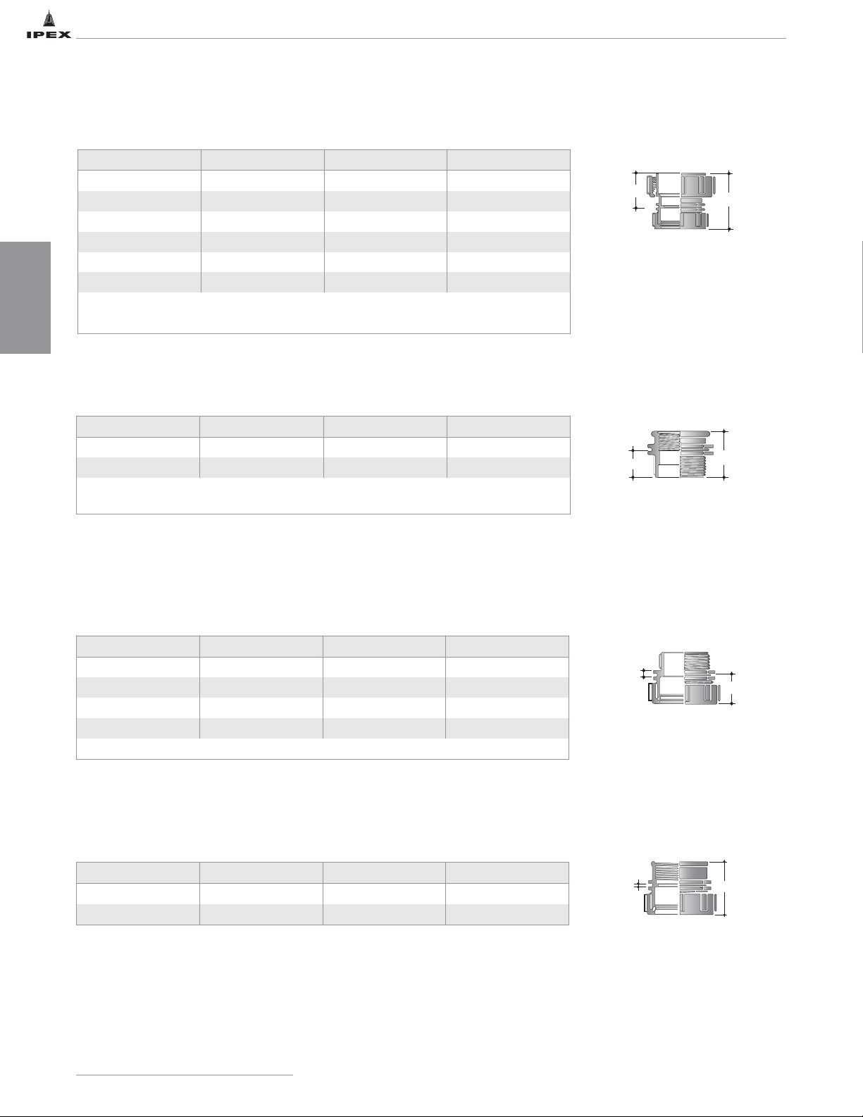
DIMENSIONS
Female Adapter MJ x Female Thread
LABLINE AND PLENUMLINE FITTING DIMENSIONS
Reducing Coupling
Male Adapter MJ x Male Thread
Threaded Adapters Male Thread x Female Thread
26
IPEX Acid Waste Piping Systems
Cat. No. Size (in) F (in) L (in)
W3921 / W3921P 2 x 1-1/2 1-9/16 2-13/16
W3931* / W3931P 3 x 1-1/2 2-3/8 3-15/32
W3932* / W3932P 3 x 2 2-1/4 3-5/16
W3941* 4 x 1-1/2 3-13/16 4-3/4
W3942* / W3942P 4 x 2 3-1/2 4-9/16
W3943 / W3943P 4 x 3 2-7/8 4-7/8
*Loose nut not included.
Loose nut permits direct connection to any Enfield fitting to provide reduction of pipe size.
Cat. No. Size (in) E (in) L (in)
W121 1-1/2 x 1-1/4 1-3/16 1-7/8
W131 1-1/2 x 1-1/2 1-3/16 1-7/8
These fittings adapt Enfield Universal Traps to other brands of threaded 1-1/4" and
1-1/2" sink outlets.
Cat. No. Size (in) E (in) L (in)
W141T / W141P 1-1/2 1/4 3/4
W142 / W142P 2 1/4 7/8
W143 3 1/4 1-11/16
W144 4 1/4 2-7/32
W141T adapts Enfield Universal Trap inlet to pipe.
Cat. No. Size (in) Z (in) L (in)
W151 / W151P 1-1/2 1/8 2
W152 / W151P 2 1/8 2-5/16
F
E
L
L
E
Z
L
L
Page 34
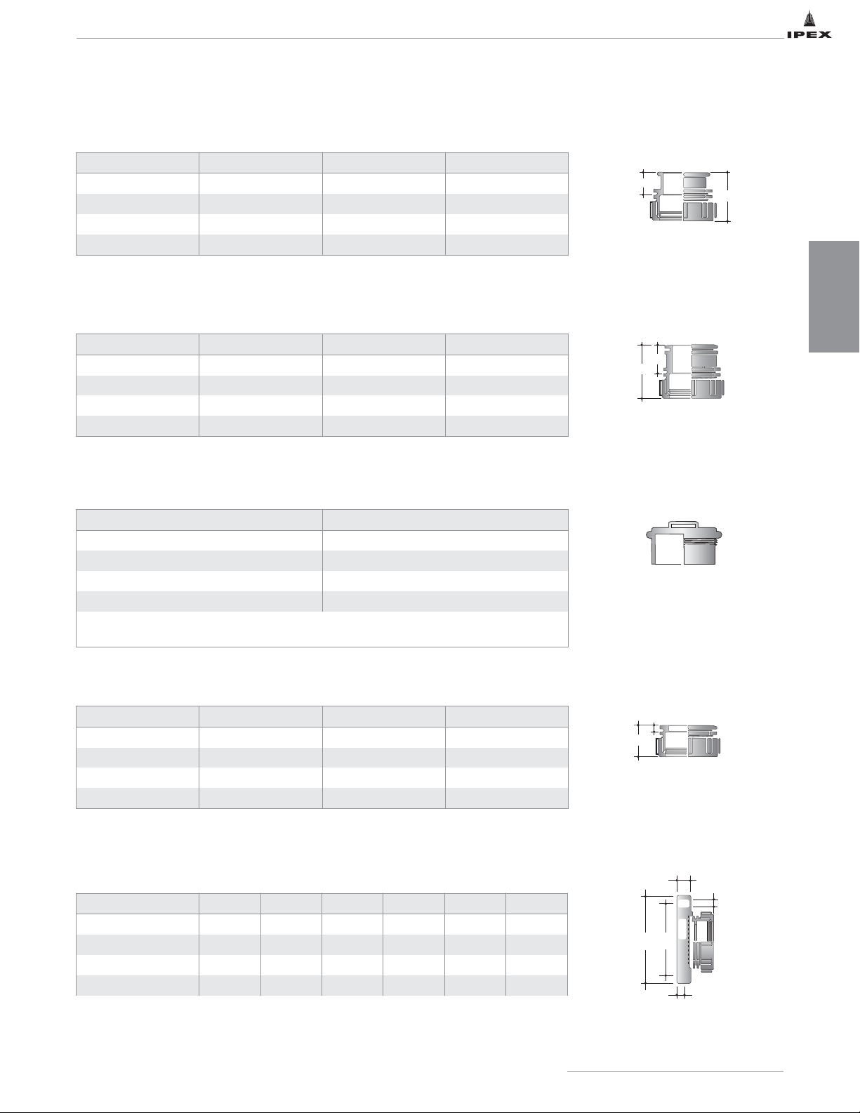
Duriron Adapter EJ x Spigot
Cleanout Plug
LABLINE AND PLENUMLINE FITTING DIMENSIONS
Glass Adapter EJ x Bead
Fabricated Cap
Fabricated Flanges
DIMENSIONS
27
IPEX Acid Waste Piping Systems
Cat. No. Size (in) E (in) L (in)
W451 1-1/2 1-1/8 1-7/8
W452 2 1-1/4 2-1/4
W453 3 1-3/4 3-9/32
W454 4 1-3/4 3-3/4
Cat. No. Size (in) E (in) L (in)
W461 1-1/2 1-9/32 2-3/16
W462 2 1-5/16 2-3/16
W463 3 1-3/4 3-1/2
W464 4 1-3/4 4
Cat. No. Size (in)
W241 / W241P 1-1/2
W242 / W242P 2
W243 / W243P 3
W244 / W244P 4
Molded with integral sealing surface, and is locked into fittings using standard nut.
Also used as test plug.
Cat. No. Size (in) E (in) L (in)
W641P 1-1/2 5/8 1-3/4
W642P 2 1/2 1-3/4
W643P 3 5/8 2-3/4
W644P 4 3/4 3-1/2
Cat. No. Size (in) A (in) B (in) C (in) D (in) M (in)
W361P 1-1/2 3-7/8 5 3/4 1-1/2 9/16
W362P 2 4-3/4 5-15/16 3/4 1-5/8 11/16
W363P 3 6 7-7/16 3/4 2-1/8 11/16
W364P 4 7-1/2 9 3/4 2-1/8 11/16
E
L
E
L
E
L
C
E
B
A
D
Page 35
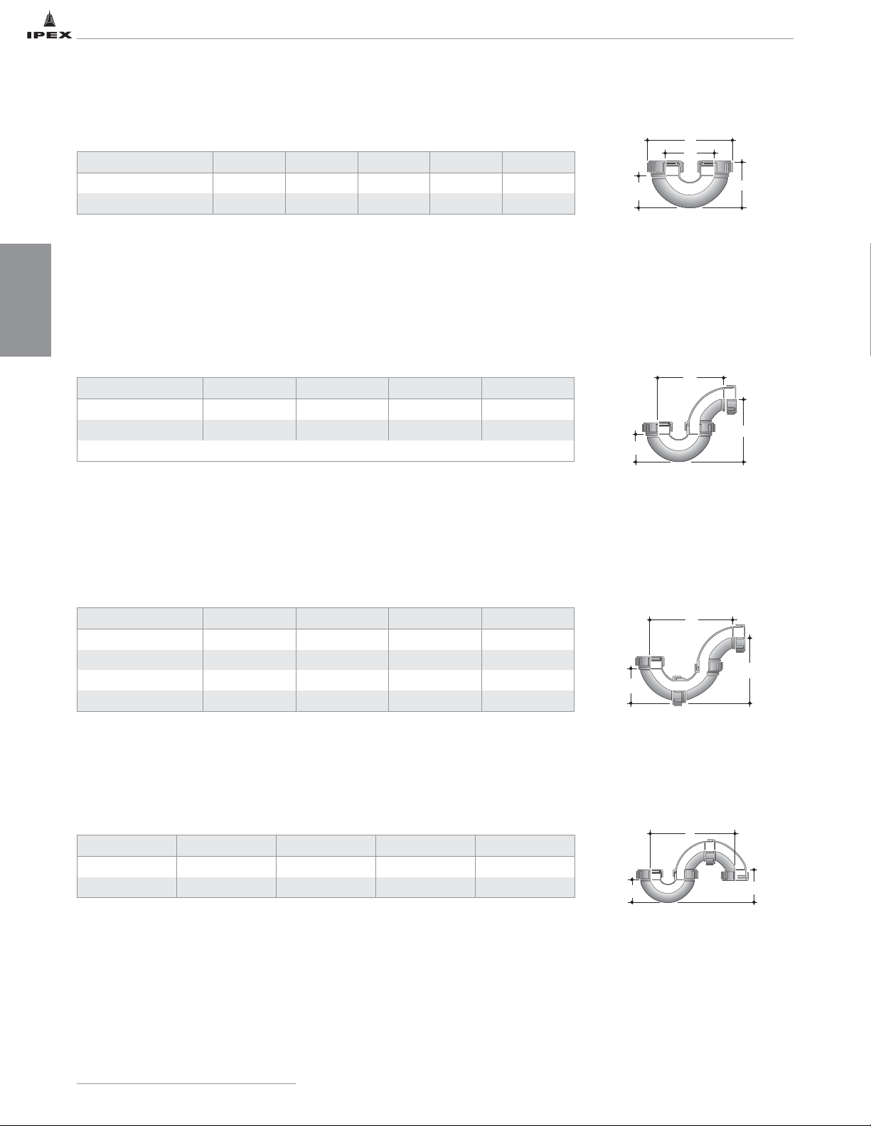
LABLINE AND PLENUMLINE FITTING DIMENSIONS
Vent Loop / U Bend
P Trap 2-piece
P Trap 3-piece
S Trap 3-piece
Cat. No. Size (in) E (in) F (in) L (in) M (in)
W1011 / W1011P 1-1/2 2-9/16 3-1/2 5-3/4 3-11/32
W1012 / W1012P 2 2-7/8 4-3/16 6-13/16 3-7/8
Cat. No. Size (in) A (in) B (in) C (in)
W1021 / W1021P 1-1/2 5-7/8 5-3/8 2-9/16
W1022 / W1022P 2 6-15/16 6-3/4 2-7/8
Configuration may be changed to suit by simply pivoting the ell.
Cat. No. Size (in) A (in) B (in) C (in)
WT11 / WT11P 1-1/2 8 6-13/16 3-1/2
WT12 / WT12P 2 9-1/4 8 4-1/4
WT13 / WT13P 3 12 11 6
WT14 / WT14P 4 15-9/16 15-7/8 7-13/16
Cat. No. Size (in) A (in) B (in) C (in)
W1031 1-1/2 9-1/4 3-1/8 2-1/2
W1032 2 10-3/4 3-13/16 2-7/8
IPEX Acid Waste Piping Systems
28
DIMENSIONS
L
F
E
A
C
M
B
A
B
C
A
C
B
Page 36
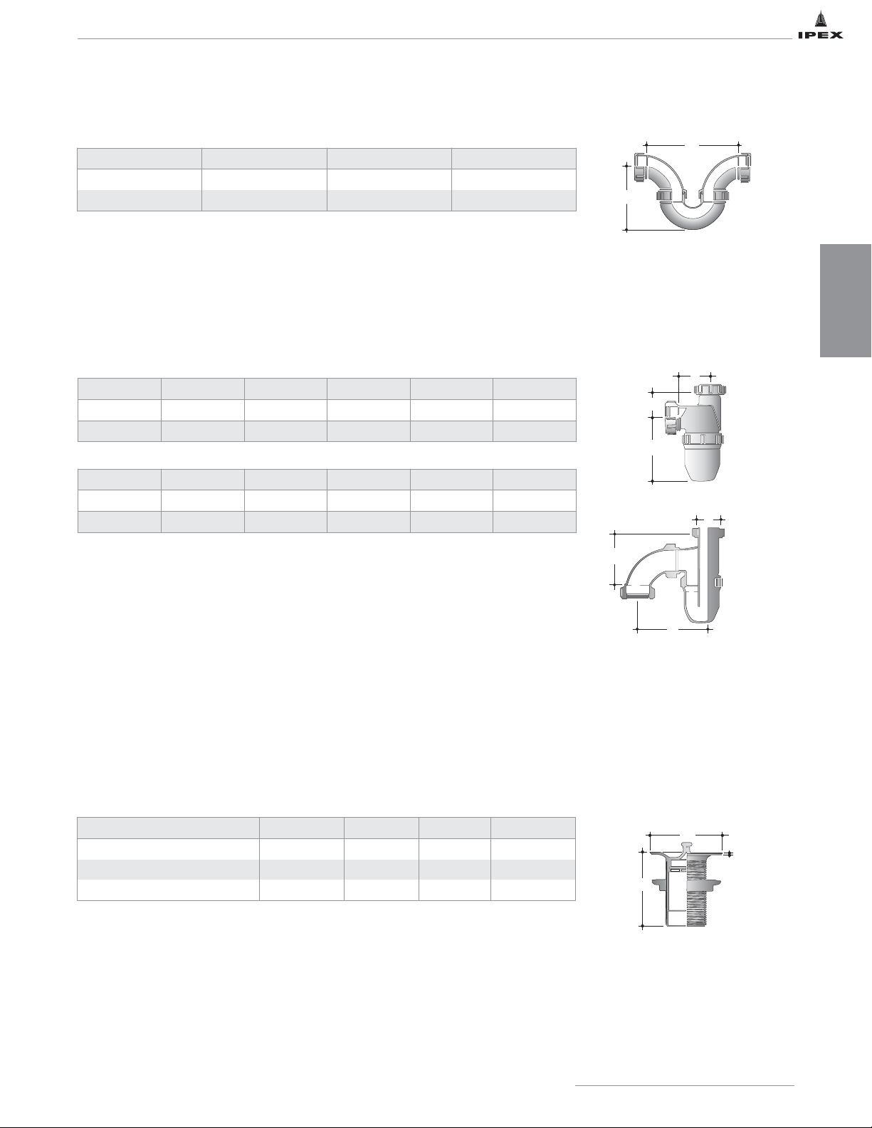
LABLINE AND PLENUMLINE FITTING DIMENSIONS
Note: Three inch deep seal Universal Traps have 1-1/2" female threaded inlet which
connects directly to Enfield cup sinks and sink outlets or can be adapted to other brands
by means of adapters W121 and W131. All universal traps contain nitrile gaskets. Other
special chemical resistance gaskets are available upon request.
*Universal traps are Anti-Siphon design.
Running Trap 3-piece
Universal Trap
Sink Outlets & Standing Waste
S-type
P-type
Cat. No. Size (in) A (in) B (in)
W1041 / W1041P 1-1/2 7-7/8 5-3/8
W1042 / W1042P 2 9-1/8 6-3/4
Type Cat. No. Size (in) D (in) E (in) F (in)
“P” W501 1-1/2 3-3/8 2-5/16 5-9/16
“P” W511* 1-1/2 3-3/8 2-3/8 6-3/8
Type Cat. No. Size (in) A (in) B (in) C (in)
“S” W5015 1-1/2 1-1/2 4-5/8 5-1/2
“S” W5115* 1-1/2 1-1/2 4-5/8
Cat. No. Size (in) A (in) *B (in) C (in)
W301 (outlet) 1-1/2 3-3/4 4 1/8
W311 (outlet) 1-1/2 2-7/8 4 1/8
W321 (standing waste tube) 1-1/2 x 7 – – –
IPEX Acid Waste Piping Systems
29
DIMENSIONS
* Clear Base made from TPX (Methylpentene Copolymer)
Sink outlets include integral strainer and removable plug.
Overflows like sink outlets are available in black.
A
B
D
E
F
A
B
C
A
C
B
Page 37
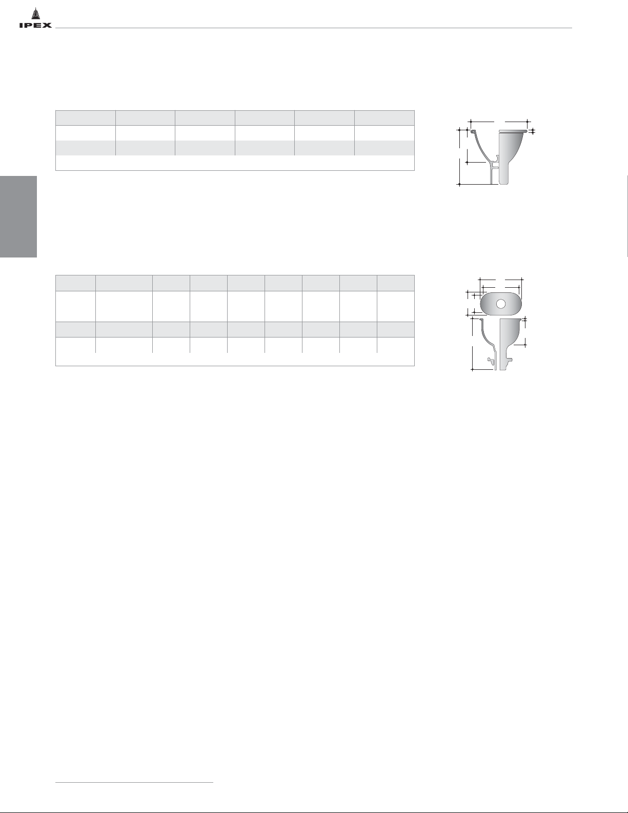
LABLINE AND PLENUMLINE FITTING DIMENSIONS
Cup Sink - Round
Cup Sink - Oval
Cat. No. Size (in) A (in) B (in) C (in) D (in)
W401 6 x 4 deep 6-1/2 6-1/2 5/16 4
W402 4 x 4 deep 4-1/16 5-9/32 5/32 2-11/16
Round cup sink with 1-1/2" outlet is only available in black.
Cat. No. Size (in) A (in) B (in) C (in) D (in) E (in) F (in) G (in)
W497 6 x 3 deep 7-1/16 5-7/8 1/4 4-1/4 8-1/2 4 2-7/8
Cat. No. Size (in) A (in) B (in) C (in) D (in) E (in) F (in) G (in)
W498 9 x 3 deep 10-3/8 9 1/4 5-1/4 8-15/16 4-7/16 2-15/16
Oval cup sink with 1-1/2" outlet is only available in black.
IPEX Acid Waste Piping Systems
30
DIMENSIONS
A
C
D
B
A
B
G
F
C
E
D
Page 38
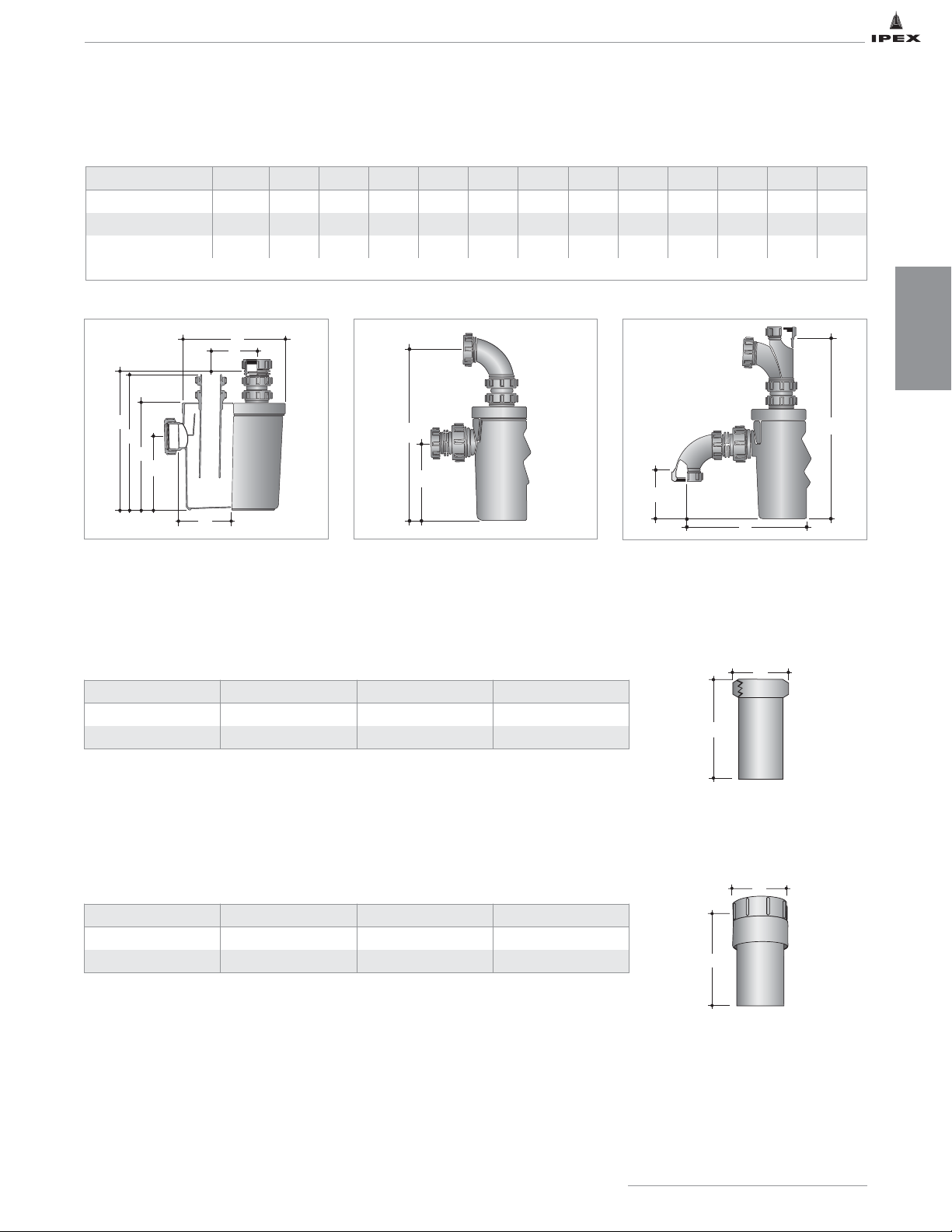
ACCESSORIES
Dilution Traps
Note: Dilution traps should not be used as neutralization tanks.
* Viton gasket
Tailpiece Adapter Brass Compression Nut
Swivel Sink Strainer Adapter
Cat. No. Size (in) A (in) B (in)
W551 1-1/2 1-5/8 2-1/4
W5512 1-1/2 12 2-1/4
Cat. No. Size (in) A (in) B (in)
W303 1-1/2 3 1.7
W3012 / W3012P 1-1/2 12 1.7
Cat. No. Size (in) A (in) B (in) C (in) D (in) E (in) F (in) G (in) H (in) I (in) J (in) K (in) L (in)
W601 1-1/2 9 4 12-1/2 12-3/8 9-5/8 6-5/8 4-3/4 14 6-5/8 4-3/8 16 9-3/4
W611* clear base 1-1/2 9 4 12-1/2 12-3/8 9-5/8 6-5/8 4-3/4 14 6-5/8 4-3/8 16 9-3/4
upon request 2 9 4 12-1/2 12-3/8 9-5/8 6-5/8 4-3/4 14-3/8 6-5/8 4-3/8 17 9-7/8
* Clear base is made of TPX (Methylpentene Copolymer)
IPEX Acid Waste Piping Systems
31
DIMENSIONS
A
B
C
D
E
F
G
H
I
K
J
L
Brass Nut
B
A
B
A
Page 39
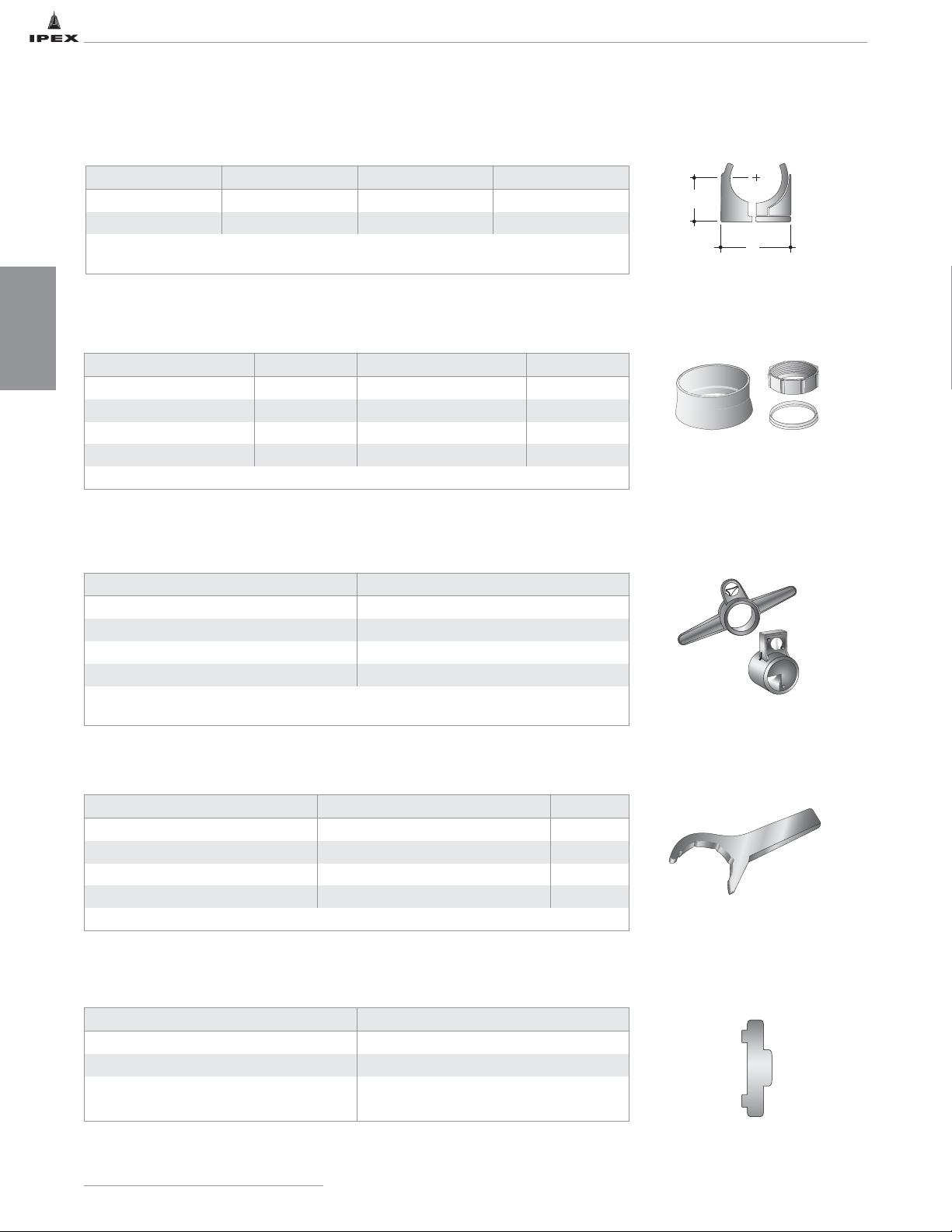
ACCESSORIES
Grooving Tool
Spanner
ElastoliveTM/ Nut
Pipe Clip
Spanner for Brass Plug
Cat. No. Size (in) A (in) B (in)
W251 1-1/2 1-5/8 2-3/8
W252 2 1-3/4 3-3/3
This “snap-in” type clip permits thermal movement of the pipe.
It is installed using a single screw or bolt.
Elastolive* Cat. No. Size (in) Nut Cat. No. Size (in)
W221NH / W221NHP 1-1/2 W231 / W231P 1-1/2
W222NH / W222NHP 2 W232 / W232P 2
W223NH / W223NHP 3 W233 / W233P 3
W224NH / W224NHP 4 W234 / W234P 4
* No-heat olive.
Cat. No. Size (in)
W261 1-1/2
W262 2
W263 3
W264 4
3" and 4" grooving tools have integral handles which facilitate efficient and easy groove
cutting.
Spanner only Cat. No. Grooving/Spanner Wrench Set Cat. No. Size (in)
W2611 W261CS 1-1/2
W2622 W262CS 2
W2633 W263CS 3
W2644 W264CS 4
Spanners are supplied with each grooving tool, but can also be purchased separately.
Cat. No. Size (in)
W2611 1-1/2
W2622 2
W2633 3
W2644 4
IPEX Acid Waste Piping Systems
32
DIMENSIONS
A
B
Page 40
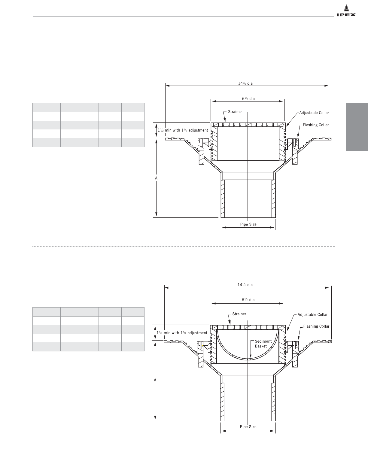
FLOWAYTMPOLYPROPYLENE DRAIN DIMENSIONS – ADJUSTABLE
All drains are minimum 3" diameter.
* For 2" drains, use the appropriate Enfield or
Labline reducer.
OPTIONS
• Gas tight plug
• Allenhead vandal-proof screws
• Male iron pipe thread outlet
All drains are minimum 3" diameter.
* For 2" drains, use the appropriate Enfield or
Labline reducer.
OPTIONS
• Gas tight plug
• Allenhead vandal-proof screws
• Male iron pipe thread outlet
SPECIFICATION: Floway series F1000 polypropylene adjustable floor drain with 6" diameter strainer and plain end outlet.
Body with 14-1/2" diameter flange, and non-puncturing style flashing collar with weep holes.
SERIES F1000
ADJUSTABLE FLOOR DRAIN
SPECIFICATION: Floway series F1000 polypropylene adjustable floor drain with 6" diameter strainer, sediment basket, and
plain end outlet. Body with 14-1/2" diameter flange, and non-puncturing style flashing collar with weep holes.
SERIES F1000
ADJUSTABLE FLOOR DRAIN
WITH SEDIMENT BASKET
Cat. No. Outlet Size (in) A (in) Wgt (lbs)
F1201 2* 10-5/8 3.2
F1301P 3 7 2.7
F1401P 4 7 2.8
F1601P 6 7 3.1
Cat. No. Outlet Size (in) A (in) Wgt (lbs)
F1202 2* 10-5/8 3.2
F1302P 3 7 2.7
F1402P 4 7 2.8
F1602P 6 7 3.1
IPEX Acid Waste Piping Systems
33
DIMENSIONS
Page 41
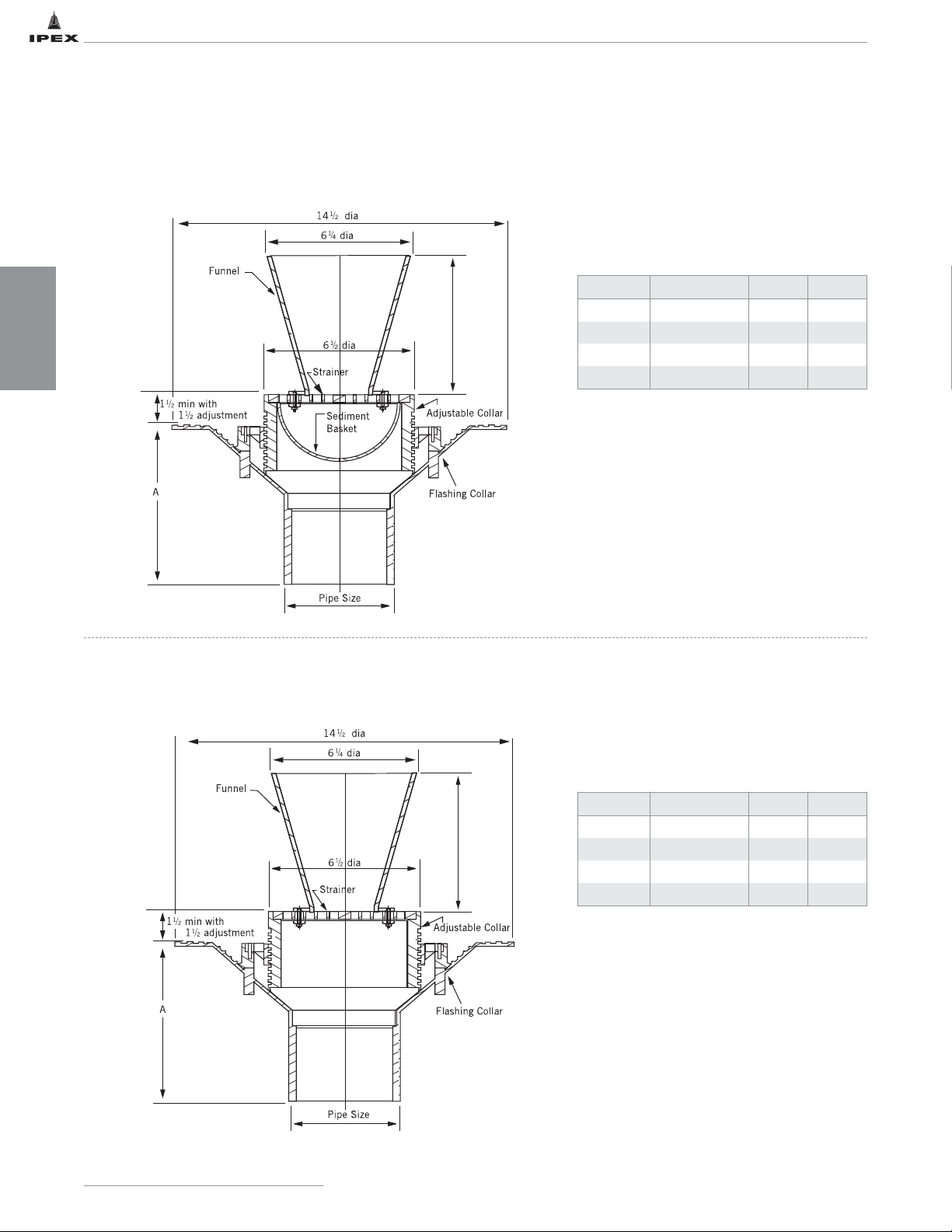
FLOWAYTMPOLYPROPYLENE DRAIN DIMENSIONS – ADJUSTABLE
All drains are minimum 3" diameter.
* For 2" drains, use the appropriate Enfield or
Labline reducer.
OPTIONS
• Gas tight plug
• Allenhead vandal-proof screws
• Male iron pipe thread outlet
All drains are minimum 3" diameter.
* For 2" drains, use the appropriate Enfield or
Labline reducer.
OPTIONS
• Gas tight plug
• Allenhead vandal-proof screws
• Male iron pipe thread outlet
SPECIFICATION: Floway series F1000 polypropylene adjustable floor drain with 6" diameter strainer, sediment basket, 6" diameter
funnel and plain end outlet. Body with 14-1/2" diameter flange, and non-puncturing style flashing collar with weep holes.
SERIES F1000
ADJUSTABLE FLOOR DRAIN WITH SEDIMENT
BASKET AND 6" ROUND FUNNEL
SPECIFICATION: Floway series F1000 polypropylene adjustable floor drain with 6" diameter strainer, 6" diameter funnel and
plain end outlet. Body with 14-1/2" diameter flange, and non-puncturing style flashing collar with weep holes.
SERIES F1000
ADJUSTABLE FLOOR DRAIN WITH
6" ROUND FUNNEL
Cat. No. Outlet Size (in) A (in) Wgt (lbs)
F1203 2* 10-5/8 3.2
F1303P 3 7 2.7
F1403P 4 7 2.8
F1603P 6 7 3.1
Cat. No. Outlet Size (in) A (in) Wgt (lbs)
F1204 2* 10-5/8 3.2
F1304P 3 7 2.7
F1404P 4 7 2.8
F1604P 6 7 3.1
IPEX Acid Waste Piping Systems
34
DIMENSIONS
Page 42
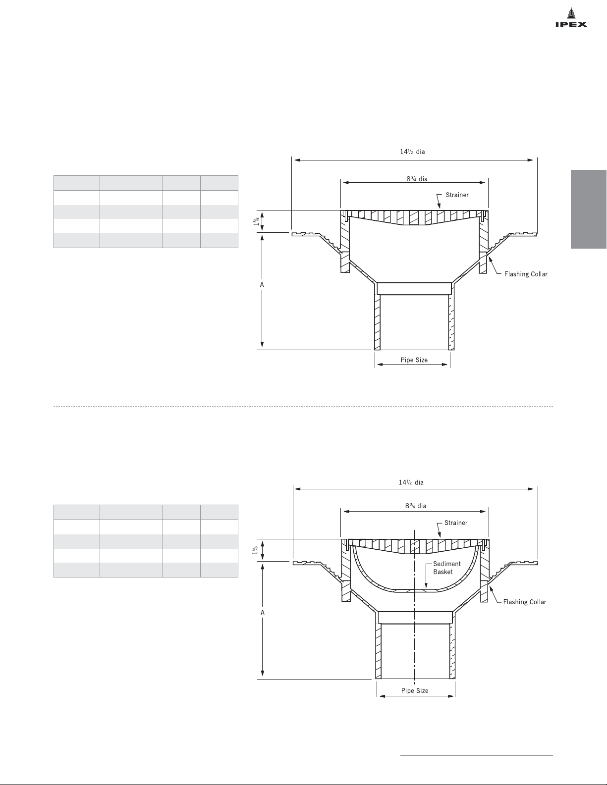
FLOWAYTMPOLYPROPYLENE DRAIN DIMENSIONS – NON-ADJUSTABLE
All drains are minimum 3" diameter.
* For 2" drains, use the appropriate Enfield or
Labline reducer.
OPTIONS
• Gas tight plug
• Allenhead vandal-proof screws
• Male iron pipe thread outlet
All drains are minimum 3" diameter.
* For 2" drains, use the appropriate Enfield or
Labline reducer.
OPTIONS
• Gas tight plug
• Allenhead vandal-proof screws
• Male iron pipe thread outlet
SPECIFICATION: Floway series F4000 polypropylene non-adjustable floor drain with 8-1/2" diameter strainer and plain end
outlet. Body with 14-1/2" diameter flange, and non-puncturing style flashing collar with weep holes.
SERIES F4000
NON-ADJUSTABLE FLOOR DRAIN
SPECIFICATION: Floway series F4000 polypropylene non-adjustable floor drain with 8-1/2" diameter strainer, sediment basket,
and plain end outlet. Body with 14-1/2" diameter flange, and non-puncturing style flashing collar with weep holes.
SERIES F4000
NON-ADJUSTABLE FLOOR DRAIN
WITH SEDIMENT BASKET
Cat. No. Outlet Size (in) A (in) Wgt (lbs)
F4201 2* 10-5/8 2.8
F4301P 3 7 2.3
F4401P 4 7 2.5
F4601P 6 7 2.7
Cat. No. Outlet Size (in) A (in) Wgt (lbs)
F4202 2* 10-5/8 2.8
F4302P 3 7 2.3
F4402P 4 7 2.5
F4602P 6 7 2.7
IPEX Acid Waste Piping Systems
35
DIMENSIONS
Page 43
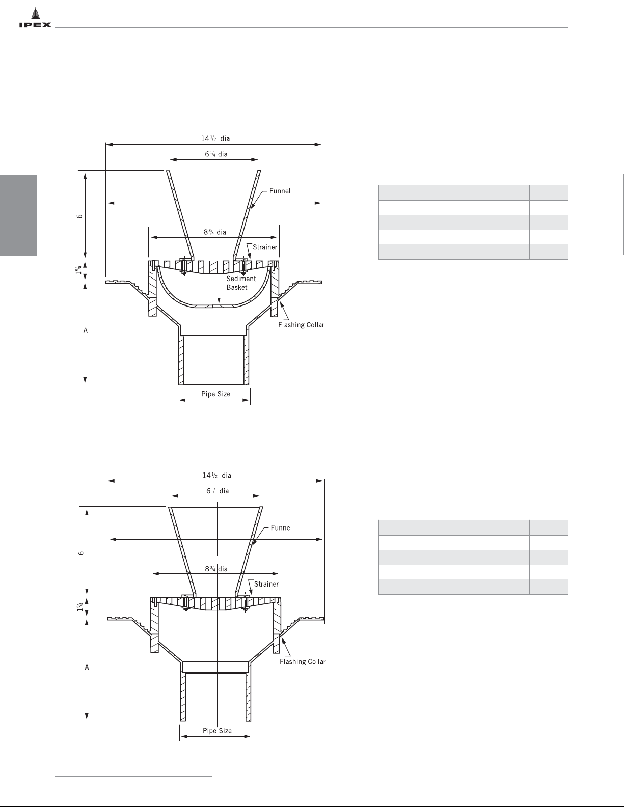
FLOWAYTMPOLYPROPYLENE DRAIN DIMENSIONS – NON-ADJUSTABLE
All drains are minimum 3" diameter.
* For 2" drains, use the appropriate Enfield or
Labline reducer.
OPTIONS
• Gas tight plug
• Allenhead vandal-proof screws
• Male iron pipe thread outlet
All drains are minimum 3" diameter.
* For 2" drains, use the appropriate Enfield or
Labline reducer.
OPTIONS
• Gas tight plug
• Allenhead vandal-proof screws
• Male iron pipe thread outlet
SPECIFICATION: Floway series F4000 polypropylene non-adjustable floor drain with 8-1/2" diameter strainer, sediment
basket, 6" diameter funnel and plain end outlet. Body with 14-1/2" diameter flange, and non-puncturing style flashing collar with
weep holes.
SERIES F4000
NON-ADJUSTABLE FLOOR DRAIN
WITH SEDIMENT BASKET AND FUNNEL
SPECIFICATION: Floway series F4000 polypropylene non-adjustable floor drain with 8-1/2" diameter strainer, 6" diameter funnel
and plain end outlet. Body with 14-1/2" diameter flange, and non-puncturing style flashing collar with weep holes.
SERIES F4000
NON-ADJUSTABLE FLOOR DRAIN
WITH FUNNEL
Cat. No. Outlet Size (in) A (in) Wgt (lbs)
F4203 2* 10-5/8 2.8
F4303P 3 7 2.3
F4403P 4 7 2.5
F4603P 6 7 2.7
Cat. No. Outlet Size (in) A (in) Wgt (lbs)
F4204 2* 10-5/8 2.8
F4304P 3 7 2.3
F4404P 4 7 2.5
F4604P 6 7 2.7
IPEX Acid Waste Piping Systems
36
DIMENSIONS
1
4
Page 44
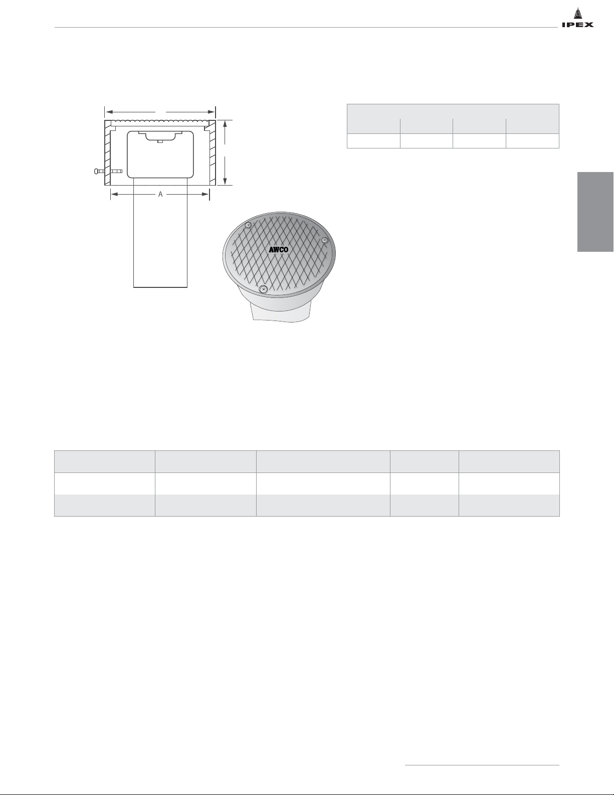
FLOWAYTMADJUSTABLE ACID WASTE CLEANOUT WITH NICKEL-BRONZE COVER
Test Test Standard Conditions Unit Safe Load
Static Load Test (a) Adjustable 72ºF / full face loading lbf 2750
Static Load Test (a) Non-Adjustable 72ºF / full face loading lbf 11000
The maximum safe live load was calculated by dividing the load at failure by two.
Note: i) The press test simulates (under laboratory conditions) the resistance to buckling of floor drains under given loadings
and surface area considerations.
ii) It is not meant to simulate every type of wheel design loading as this will vary according to the equipment supplier.
iii) The larger the wheel diameter, the more likely it is that the full face loading result can be used as an indication
of resistance to load.
iv) Polypropylene will normally recover to near its original dimensions after the load is removed.
IPEX Acid Waste Piping Systems
37
DIMENSIONS
FLOWAYTMPOLYPROPYLENE DRAIN OPERATIONAL NOTES
FEATURES:
• Available in 2", 3", 4" and 6" pipe outlet
• 12" long stub of Schedule 40 FRPP pipe
• Nickel-bronze cover plate
• Rated to 2400lb load limit
• “AWCO” designation stamped on cover
• FRPP cleanout plug inside of cover
• For use with Enfield or Labline systems
Cover Plate Dimensions
A (in) B (in) C (in) D (in)
8-5/8 9-1/8 2-3/4 7-1/4
B
C
Page 45
IPEX Acid Waste Piping Systems
38
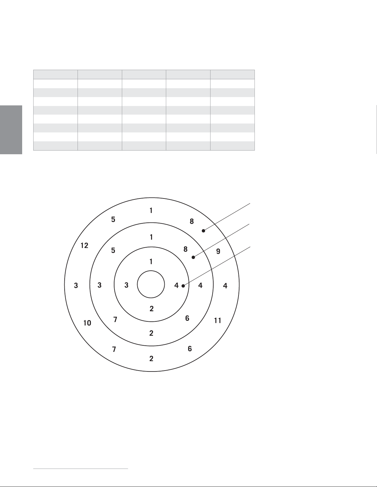
STANDARD BOLT PATTERN AND DIMENSIONS
ANSI B16.5
Flange Bolt Tightening Sequence
Tighten bolts equally following numerical sequence.
Size (in) Bolt Diameter (in) Bolt Length (in) Torque (ft lb) # of Bolt Holes
1-1/2 1/2 2-1/2 13 4
2 5/8 2-1/2 22 4
3 5/8 2-1/2 30 4
4 5/8 2-3/4 33 8
6 3/4 3-1/2 33 - 50 8
8 3/4 4 33 - 50 8
10 7/8 5 53 - 75 12
12 7/8 5-1/2 53 - 75 12
DIMENSIONS
12 - bolt pattern
8 - bolt pattern
4 - bolt pattern
Page 46

SECTION THREE: DESIGN CONSIDERATIONS
EXPANSION AND CONTRACTION
Coefficient of Thermal Expansion
The degree of thermal expansion or contraction also depends
on the system temperature differential, as well as the length
of pipe run between changes in direction. It can be
calculated using the following formula:
ΔL = Y
(T - F)
x
L
10 100
where: ΔL = expansion rate (in)
Y = expansion factor expressed in inches of
expansion per 10°F temperature change
per 100 ft. of pipe
T = maximum temperature (ºF)
F = minimum temperature (ºF)
L = length of pipe run (ft)
Note: Remember to allow for contraction when piping is to be
exposed to temperatures substantially below installation
temperature.
Example 1:
How much expansion can be expected in 215 feet of 3"
diameter FRPP pipe installed at 75°F and operating at 135°F?
Y = 0.680
Solution:
ΔL = 0.680 x 60x
215
= 0.680 x 6 x 2.15 = 8.77 inches
10 100
All piping products expand and contract with changes in temperature. Linear expansion and contraction of any pipe on the
longitudinal axis relates to the coefficient of thermal expansion (e) for the specific material used in the manufacturing of the
product. Variation in pipe length due to thermal expansion or contraction depends on the linear expansion factor (Y) and the
variation in temperature (ΔT). It should be noted that change in pipe diameter or wall thickness does not effect a change in
rates of thermal expansion or contraction.
In general, acid waste piping systems are not normally subjected to large temperature variations. Inherent flexibility of the
system is usually sufficient to accommodate anticipated expansion or contraction. However, consideration must be given in
situations where substantial temperature variations may exist.
Approximate coefficients of thermal expansion for different pipe materials are presented below.
Piping Material
“e” Coefficient
in/in/ºF
“Y” Expansion Factor
in/10ºF/100 ft
FRPP 5.67 x 10
-5
.680
NFRPP 6.62 x 10
-5
.795
FR-PVDF 8.0 x 10
-5
.960
IPEX Acid Waste Piping Systems
39
DESIGN
CONSIDERATIONS
Page 47
DESIGN
CONSIDERATIONS
40
IPEX Acid Waste Piping Systems
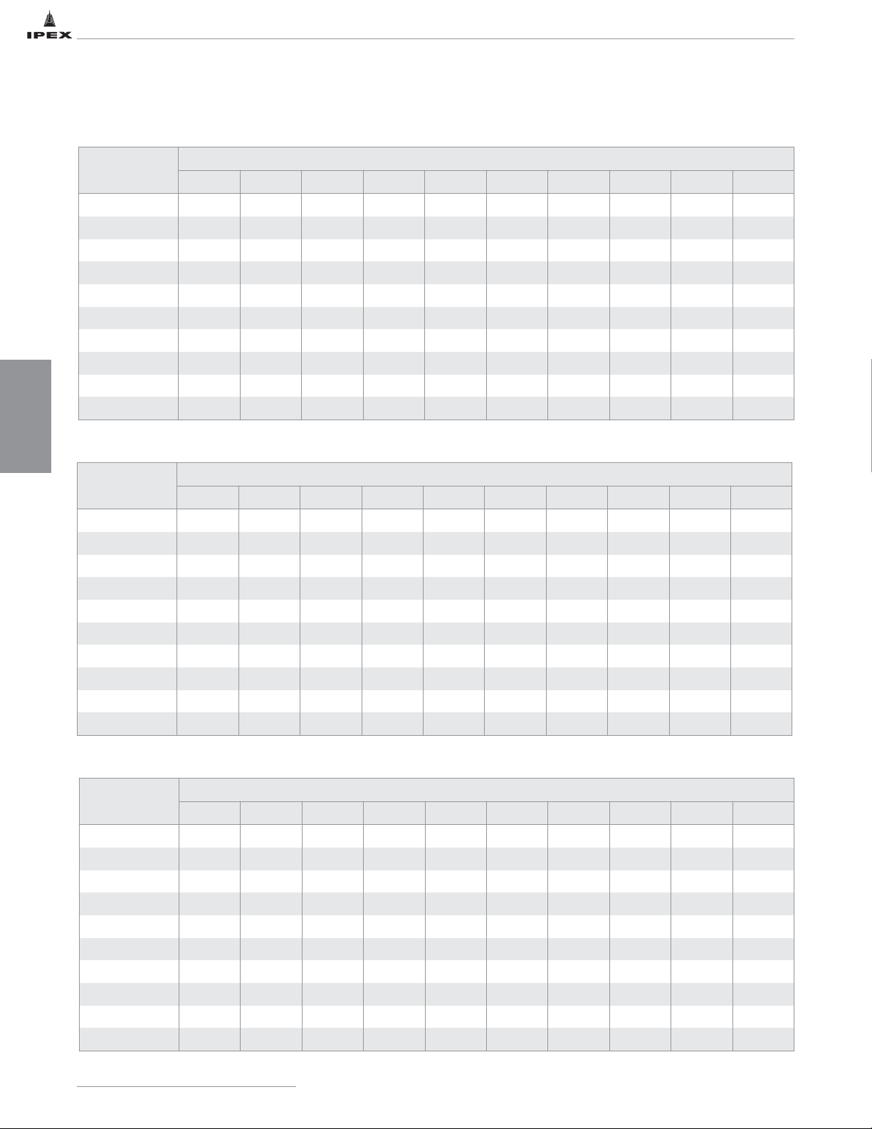
Thermal Expansion (ΔL) in inches of FRPP (0.68)
Temp. Change
T °F
Length of Run in Feet
10 20 30 40 50 60 70 80 90 100
10 0.07 0.14 0.20 0.27 0.34 0.41 0.48 0.54 0.61 0.68
20 0.14 0.27 0.41 0.54 0.68 0.82 0.95 1.09 1.22 1.36
30 0.20 0.41 0.61 0.82 1.02 1.22 1.43 1.63 1.84 2.04
40 0.27 0.54 0.82 1.09 1.36 1.63 1.90 2.18 2.45 2.72
50 0.34 0.68 1.02 1.36 1.70 2.04 2.38 2.72 3.06 3.40
60 0.41 0.82 1.22 1.63 2.04 2.45 2.86 3.26 3.67 4.08
70 0.48 0.95 1.43 1.90 2.38 2.86 3.33 3.81 4.28 4.76
80 0.54 1.09 1.63 2.18 2.72 3.26 3.81 4.35 4.90 5.44
90 0.61 1.22 1.84 2.45 3.06 3.67 4.28 4.90 5.51 6.12
100 0.68 1.36 2.04 2.72 3.40 4.08 4.76 5.44 6.12 6.80
Temp. Change
T °F
Length of Run in Feet
10 20 30 40 50 60 70 80 90 100
10 0.08 0.16 0.24 0.32 0.40 0.48 0.56 0.64 0.72 0.80
20 0.16 0.32 0.48 0.64 0.80 0.95 1.11 1.27 1.43 1.59
30 0.24 0.48 0.72 0.95 1.19 1.43 1.67 1.91 2.15 2.39
40 0.32 0.64 0.95 1.27 1.59 1.91 2.23 2.54 2.86 3.18
50 0.40 0.80 1.19 1.59 1.99 2.39 2.78 3.18 3.58 3.98
60 0.48 0.95 1.43 1.91 2.39 2.86 3.34 3.82 4.29 4.77
70 0.56 1.11 1.67 2.23 2.78 3.34 3.90 4.45 5.01 5.57
80 0.64 1.27 1.91 2.54 3.18 3.82 4.45 5.09 5.72 6.36
90 0.72 1.43 2.15 2.86 3.58 4.29 5.01 5.72 6.44 7.16
100 0.80 1.59 2.39 3.18 3.98 4.77 5.57 6.36 7.16 7.95
Thermal Expansion (ΔL) in inches of NFRPP (0.795)
Temp. Change
T °F
Length of Run in Feet
10 20 30 40 50 60 70 80 90 100
10 0.10 0.19 0.29 0.38 0.48 0.58 0.67 0.77 0.86 0.96
20 0.19 0.38 0.58 0.77 0.96 1.15 1.34 1.54 1.73 1.92
30 0.29 0.58 0.86 1.15 1.44 1.73 2.02 2.30 2.59 2.88
40 0.38 0.77 1.15 1.54 1.92 2.30 2.69 3.07 3.46 3.84
50 0.48 0.96 1.44 1.92 2.40 2.88 3.36 3.84 4.32 4.80
60 0.58 1.15 1.73 2.30 2.88 3.46 4.03 4.61 5.18 5.76
70 0.67 1.34 2.02 2.69 3.36 4.03 4.70 5.38 6.05 6.72
80 0.77 1.54 2.30 3.07 3.84 4.61 5.38 6.14 6.91 7.68
90 0.86 1.73 2.59 3.46 4.32 5.18 6.05 6.91 7.78 8.64
100 0.96 1.92 2.88 3.84 4.80 5.76 6.72 7.68 8.64 9.60
Thermal Expansion (ΔL) in inches of FR-PVDF
Page 48
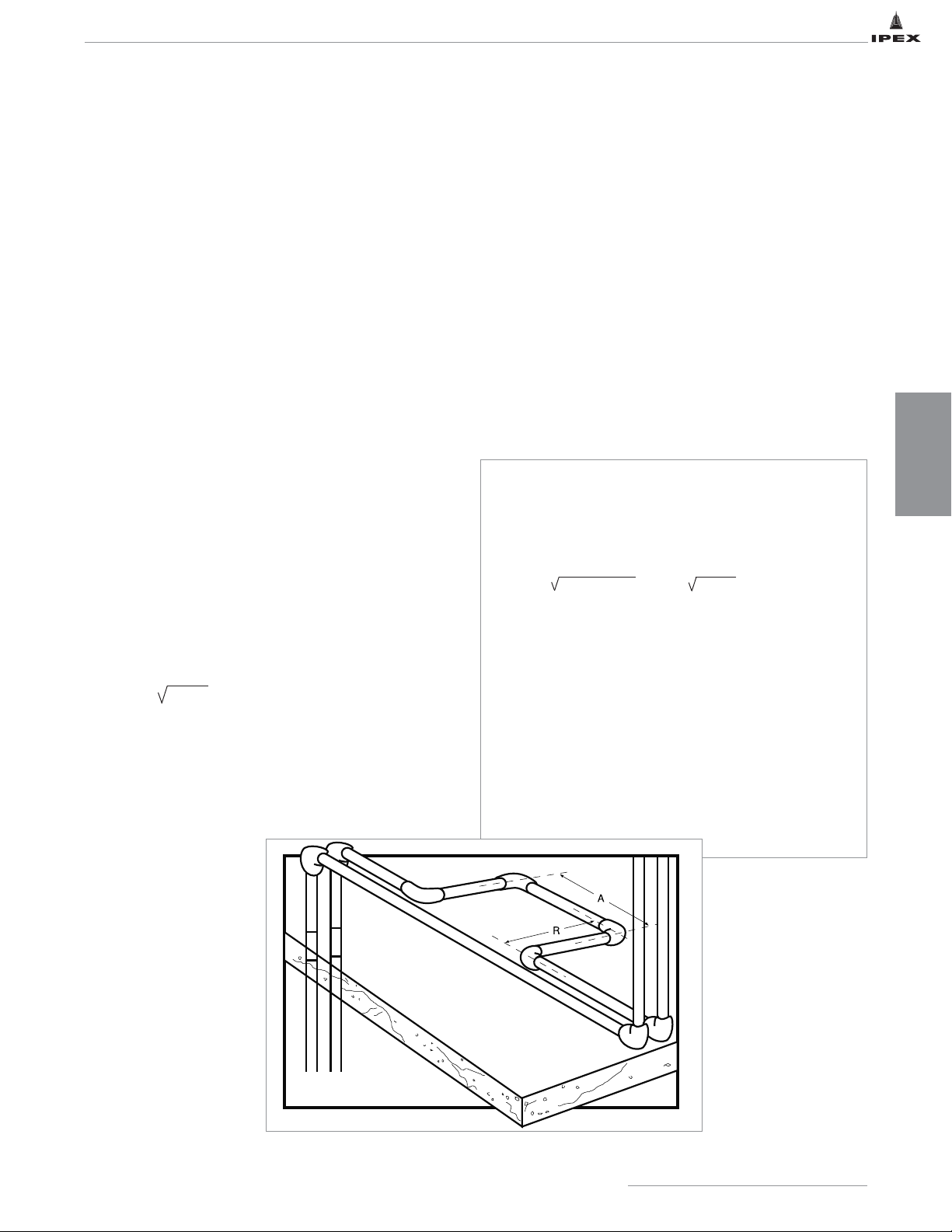
Thermal Movement
There are various ways to accommodate expansion and contraction in acid waste systems.
They are:
• Expansion Offsets
• Expansion Loops
• Expansion Joints
Expansion Offset
Flame retardant polypropylene expands at a unit rate of 0.720 in. per 10ºF (-6.5ºC) change per 100 ft of pipe. This can be
accommodated by using the flexibility of polypropylene pipe at changes in pipe direction. Install the system free of strain
using loose fitting pipe clips allowing the pipe to float.
When total temperature change is less than 30°F (-17ºC), special provisions for accommodating thermal expansion are not
generally required, especially when the line includes several directional changes and thus provides considerable inherent
flexibility. Caution should be exercised with threaded connections, as they are more vulnerable to failure by bending stresses.
Where such conditions exist, it is advisable to use a flanged connection.
Expansion Loops
Normally, piping systems are designed with sufficient
directional changes providing inherent flexibility to
compensate for expansion and contraction. However, when
this is not the case or when there is reasonable doubt as to
adequate flexibility of the system, expansion loops or
expansion joints should be designed into the system. If an
expansion loop (fabricated with 90° elbows and straight pipe
as depicted) is used, the length R should be determined by
using the following formula to ensure it is of sufficient length
to absorb expansion and contraction movement without
damage.
R = K D ΔL
K = Material constant: 1.44 for PP, 1.85 for PVDF
R = Expansion loop leg length (ft.)
D = Nominal outside diameter of pipe (in.)
ΔL = Dimensional change due to thermal expansion or
contraction (in.)
A=
1
/2 R
Example 3:
For 3" SCH 40 FRPP pipe, ΔT = 70°F, run = 100', ΔL = 5.04
How long should the expansion loop legs be in order to
compensate for the expansion?
R = 1.44 3.50 x 4.76 = 1.44 16.66 = 5.87 ft.
A =
1
/2 R A = 2.935 ft
In situations where straight runs of pipe are long or the
ends of a straight run are restricted from movement or
where the system is restrained, flexibility must be inserted
into a pipe system through the introduction of flexural
offsets. An example of a method for inserting flexibility in
these situations is graphically presented. In each case, rigid
supports or restraints should not be placed within the leg
length of an expansion loop, offset or bend.
DESIGN
CONSIDERATIONS
41
IPEX Acid Waste Piping Systems
Page 49
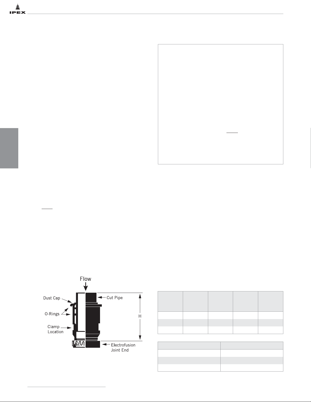
Expansion Joints
Enfield Polypropylene pipe systems are installed in several
different climates across North America. As a result, these
systems must contend with expansion and contraction
brought about by temperature change. To overcome this
problem and avoid possible damage to the installation,
Enfield Expansion Joints are specifically designed to
eliminate the stresses and strains caused by thermal movement.
When an expansion joint is installed, care should be taken in
the fixing of the pipe to ensure an accurate linear “thrust and
pull” movement. Any pipe clamp should allow the pipe to
slide freely. The housing of the expansion joint on the other
hand should always be firmly anchored to allow the sliding
member to accept any movement.
On stack installations, where expansion and contraction are a
concern, an expansion joint should be installed at every floor
level where the stack is connected. If there are no
connections, an expansion joint should be installed at every
second floor level.
In vertical applications, cut-off access must be designed to
ensure hydrostatic test pressure does not exceed 4.33 psi. A
common method to achieve this is to install a cleanout every
10 feet in the stack.
Correct “piston-in” and “piston-out” position at the time of
installation is critical and can be calculated by the formula:
P = M – A x L
T
where: P = “out” position of inner tube in inches
M = maximum temperature
A = installation temperature
T = total temperature change
L = length of traverse in expansion joint in inches
Example 2:
Assume that a pipeline will be installed in an unheated,
exposed building with a metal roof where temperatures
range from 10°F in the winter, to 110°F in the summer. If
installation temperature is 70°F, the pipe will contract over
a 60° temperature range during cold weather and will
expand over a 40° temperature range during the summer.
Consequently, three-fifths of the line movement will be on
the contraction side or “piston-in” position, while the
remainder will be expansion. The expansion joint provides
for various lengths of movement. As a result, the inner
tube should be pulled out approximately half of the total
movement expected when the joint is installed.
Highest temperature expected: 110°F
Lowest temperature expected: 40°F
Total Change (ΔT): 70°F
Length of run: 100 feet
A 70°F ΔT on the Thermal Expansion chart (previous page)
corresponds to a 4.76" change in length (ΔL).
Installing Expansion Joints
1. The direction of fluid flow through the expansion joint
shall be from the dust cap end to the electrofusion or
mechanical joint end. For example, if the expansion joint
is being installed on a vertical system, the dust cap will
be on the top.
2. Ensure the pipe and expansion joint are clean and free
of debris.
3. The pipe is marked to show the maximum limit of travel.
4. Withdraw the pipe per the table below for the given
temperature during installation.
5. Reinstall the dust cap on the expansion joint.
6. Securely anchor the expansion joint with a metal clamp.
The diameter and the maximum width of the clamp are
shown in the table below. See the anchor placement
noted on the drawing. The expansion joint only becomes
functional when it is securely mounted.
Expansion
Joint Size
(in)
Clamp Dia.
(in)
Max. Clamp
Width
(in)
Fully
Inserted H
(in)
Total Max.
Allowable
Travel (in)
3 4.29 1.30 13.50 2.00
4 5.28 1.30 13.50 2.00
6 7.40 1.30 18.25 2.00
Temperature Distance to Withdraw (in)
Less than 32ºF 1-3/4
32 - 85ºF 1-1/2
More than 85ºF 1-1/4
IPEX Acid Waste Piping Systems
42
DESIGN
CONSIDERATIONS
Page 50
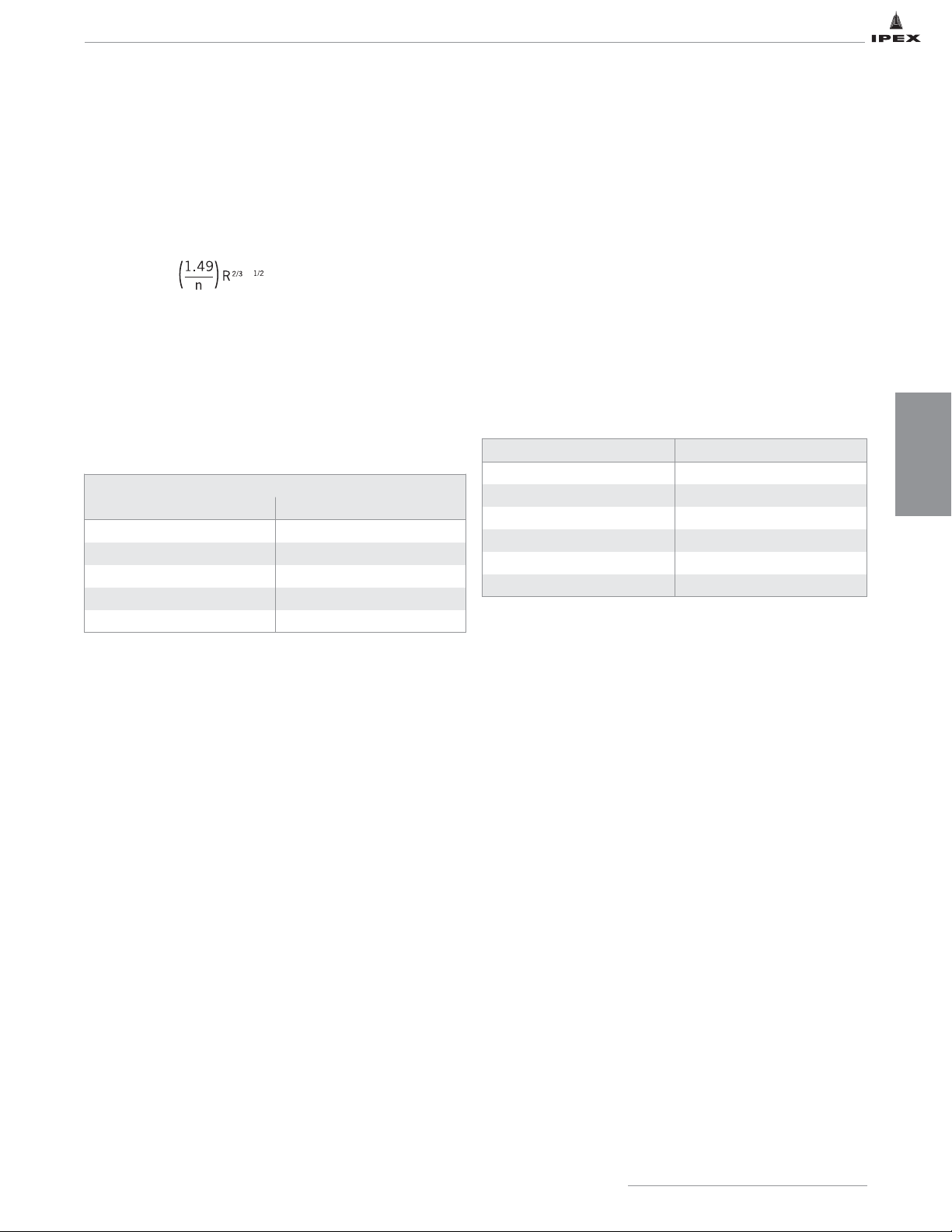
Compared to traditional pipe materials, the thermal
conductivity of thermoplastic is low and acts as an insulator.
This insulating property of plastic provides a distinct
advantage over traditional materials to retard or prevent
“sweating” or formation of condensation. The need for
insulation may, in certain instances, be completely eliminated
by using plastic. Thermal conductivity is expressed as
BTU/hr./sq.ft./ºF/in. where BTU/hr. or British Thermal Unit
per hour is defined as energy required to raise the
temperature of one pound of water (12 gallons x specific
gravity) one Fahrenheit degree in one hour. Square feet refers
to one square foot where heat is being transferred. Inch refers
to one inch of pipe wall thickness. As pipe wall thickness
increases, thermal conductivity decreases.
The coefficients of thermal conductivity of some materials
used in drainage piping are:
Copper, a good conductor of heat, will lose 2,700 BTU per
hour per square foot of surface area with a wall thickness of
1" while PP will lose only 1.2 BTU/hr.
SYSTEM SIZING
Manning Roughness Factor
Piping systems for drainage applications usually consist of
minimal to half pipe capacity flow. These discharge systems
are designed to be horizontal or slightly sloping. Friction loss
for open channel flow can be determined by the Manning
formula as follows:
V=
where: V = the average velocity at a cross section (ft./sec.)
R = the hydraulic radius (ft.)
S = slope (ft./ft.)
n = the coefficient of roughness
The Manning formula is used for liquids in a steady flow at
constant depth. Values of the coefficient n, determined by
many tests on actual pipes, are given in the following table.
The high carrying capacity of plastic piping often results in the
use of flatter grades or in the use of smaller diameter pipe.
THERMAL CONDUCTIVITY
Average Values of the Manning Roughness Factor
Material Manning n
PP / PVDF .009
Glazed surface .010
Concrete .013
Cast iron .015
Corrugated metal .022
Material BTU/hr./sq.ft./ºF/in.
PP 1.2
PVDF 1.18 to 1.32
Glass 8
Cast Iron / Carbon Steel 360
Aluminum 1,000
Copper 2,700
IPEX Acid Waste Piping Systems
43
DESIGN
CONSIDERATIONS
S
Page 51
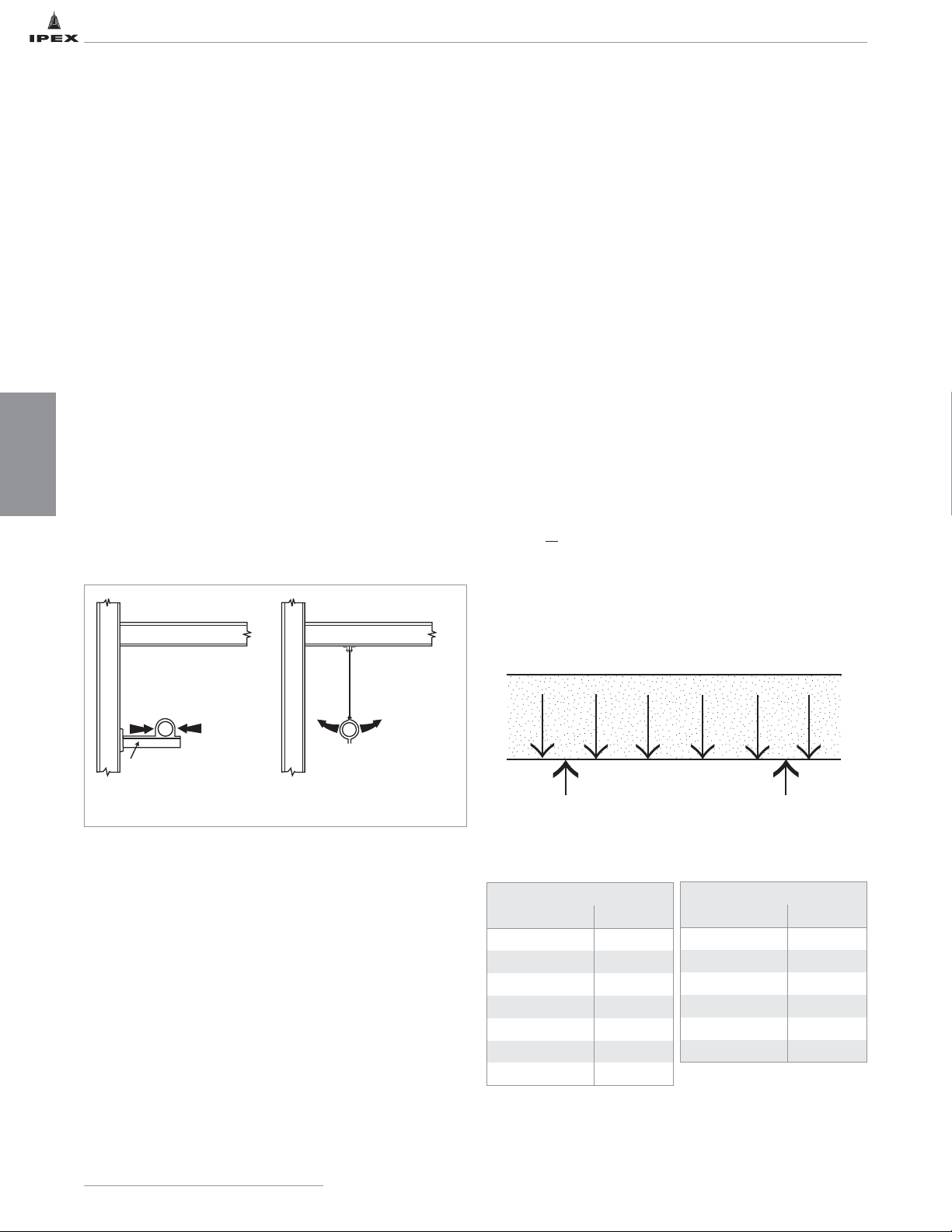
PIPE SUPPORTS AND SUPPORT SPACING
General Principles of Design and Support
Thermoplastics have very different mechanical and physical
properties compared to metals. Special attention should be
given to ways of dealing with their inherent higher thermal
expansion rates and lower pipe stiffness.
If the principles used for design and support of metal pipe
systems are applied directly to thermoplastic pipes, severe
problems may arise. Therefore, all warranties are contingent
upon adopting the following support procedures and
recommendations.
Supporting Pipes
The high coefficient of thermal expansion of plastic
compared with metals may result in considerable expansion
and contraction of the pipe runs as the temperature changes.
The principle is to control expansion by restraining the pipe
in the lateral direction while allowing free axial movement.
A hanger-type support does not provide lateral restraint to the
pipe, but it does encourage snaking and should be avoided
whenever possible.
The diagram below illustrates preferred and non-preferred
support arrangements.
In some cases, it may be physically impossible or impractical
to install a rigid support in between two widely spaced
columns. In this event hanger rods with loose fitting clips
should be used.
The frequency of supports for plastic pipes is greater than for
metal pipes. The recommended maximum distance between
supports for pipes filled with water is given in the table (See
Recommended Maximum Support Spacing) and applies to
pipes and contents at the temperature stated.
Pipe supports should be installed so that the horizontal
piping is in uniform alignment and with a uniform slope of at
least 1/8" per foot, or in accordance with the local plumbing
codes or authority having jurisdiction.
Calculation of Support Spacing
L = [(SL x E x I) / (1.302 x Wt)]
0.33
or
L = [(16 x I x BSL) / (OD x Wt)]
0.5
where:
L = Length between supports, ‘Span Length’, ft.
SL = Sag Limit, the maximum permitted vertical
deflection allowed across a span, expressed as a
percentage of the span length
E = Modulus of elasticity of the pipe material, psi
OD = Outside Diameter of the pipe, in.
BSL = Bending Stress Limit on a span of pipe under a
given load, psi
I = Moment of Inertia, in
4
= 0.04909 x (OD4- ID4)
Wt = Unit Weight, lb/in.
=πx [δ-pipe x (OD
2
- ID2) + δ-fluid x ID2]
4
δ-pipe = Density of pipe material, lb/in
3
δ-fluid = Density of the fluid, lb/in
3
ID = Inside diameter of the pipe, in.
Load is uniformly distributed along the span length
Modulus of Elasticity (E)
PP
Temperature (ºF) psi
73 200,000
90 130,000
110 97,000
140 74,000
170 61,000
200 55,000
210 53,000
PVDF
Temperature (ºF) psi
-40ºF (-40ºC) 509,000
14ºF (-10ºC) 312,000
68ºF (20ºC) 245,000
122ºF (50ºC) 162,000
176ºF (80ºC) 86,000
212ºF (100ºC) 61,000
IPEX Acid Waste Piping Systems
44
DESIGN
CONSIDERATIONS
clip allows free
axial pipe movement
fabricated angle iron support
with wide bearing area
PREFERRED
RIGID SUPPORT
lateral
restraint
no lateral restraint
restricted axial
pipe movement
NON-PREFERRED
Page 52
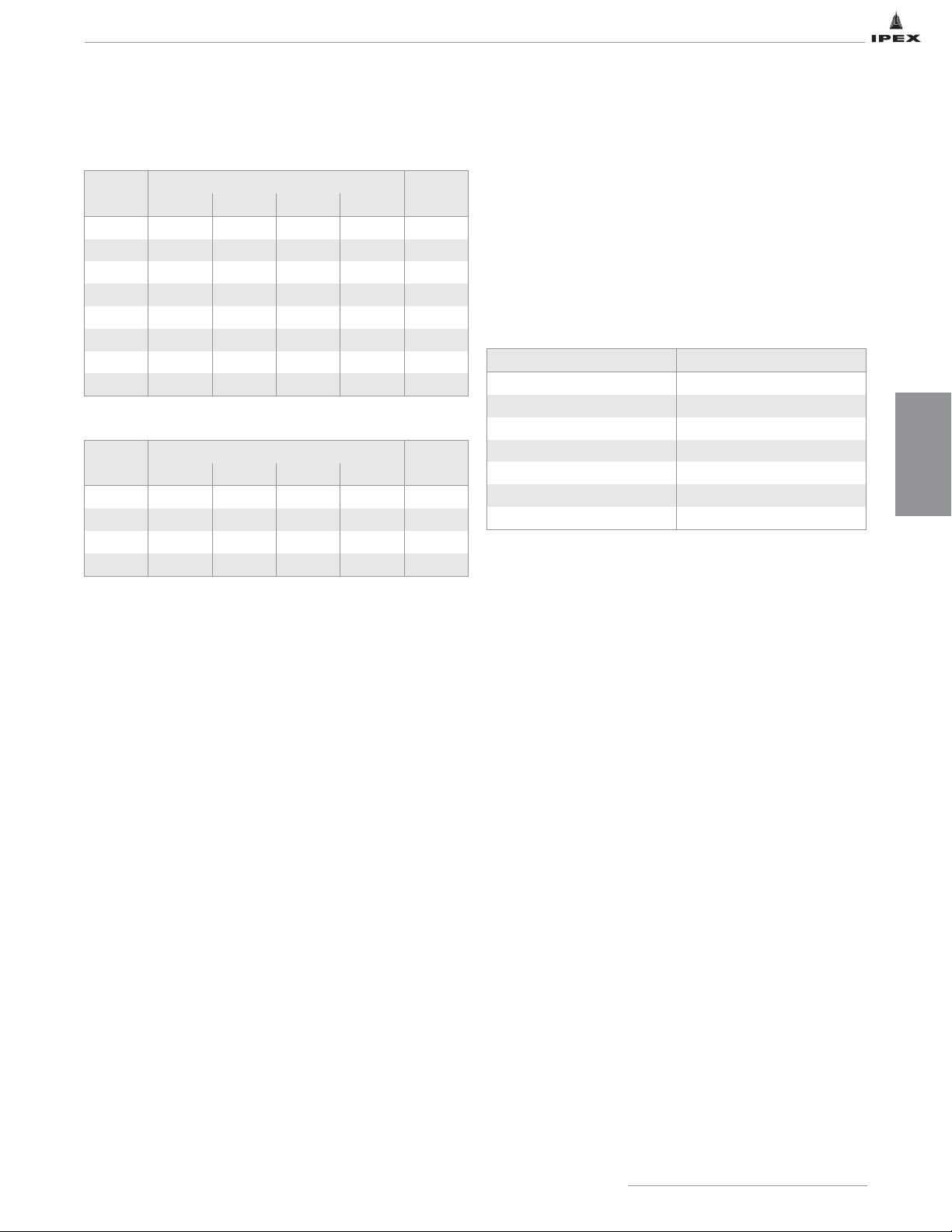
Recommended Maximum Support Spacing for PP (ft.)
Recommended Maximum Support Spacing for PVDF (ft.)
Note 1: Support spacing based on sag limit of 0.2%
Note 2: Bearing surface of support should be at least 2" wide
Support Spacing Correction Factors
When the fluid has a specific gravity greater than water
(1.0) the hanging distance of PP must be decreased by
dividing the recommended support distance by the fluid’s
specific gravity.
For PVDF, use the correction factors in the table below.
Support Spacing Correction Factors - PVDF
Pipe Size
(in)
Horizontal Pipe (ft)
Vertical
Pipe (ft)
73ºF 110ºF 170ºF 210ºF
1-1/2 3.5 3.0 2.5 2.5 10
2 4.0 3.0 2.5 2.5 10
3 5.0 4.0 3.5 3.5 10
4 6.0 4.5 4.0 4.0 10
6 7.5 5.5 5.0 4.5 10
8 8.5 6.5 5.5 5.5 10
10 9.5 7.5 6.5 6.0 10
12 10.5 8.0 7.0 6.5 10
Specific Gravity Correction Factor
1.0 1.00
1.1 0.98
1.2 0.96
1.4 0.93
1.6 0.90
2.0 0.85
2.5 0.80
Pipe Size
(in)
Horizontal Pipe (ft)
Vertical
Pipe (ft)
73ºF 110ºF 170ºF 210ºF
1-1/2 3.5 3.0 2.5 2.5 10
2 4.0 3.0 2.5 2.5 10
3 5.0 4.0 3.5 3.5 10
4 6.0 4.5 4.0 4.5 10
IPEX Acid Waste Piping Systems
45
DESIGN
CONSIDERATIONS
Page 53
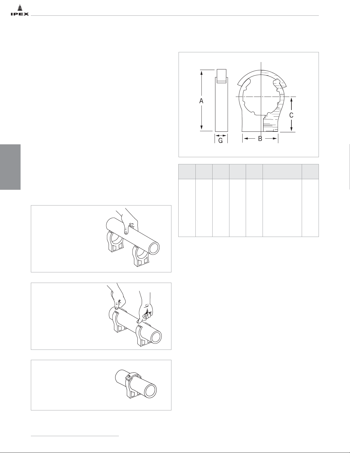
DESIGN
CONSIDERATIONS
46
IPEX Acid Waste Piping Systems
PIPE CLIPS AND HANGERS
Pipe Clips
All pipe clips should permit free axial pipe movement at all
temperatures and should provide adequate bearing support to
the pipe.
Metal clips and supports should be free of sharp edges to
prevent damaging the pipe.
Cobra Pipe Clips
Good installation of plastic piping is largely dependent on the
types of support and pipe clips selected. Clips should not
grip the pipe tightly; but allow free axial pipe movement as
the pipe expands and contracts. Correctly placed anchors,
expansion loops and free pipe lengths at changes in
direction, can then control expansion, thereby avoiding
unsightly pipe snaking.
The Cobra clip allows this free pipe movement by minimizing
friction between pipe and clip.
Also, the Cobra clip has an efficient single point fixing, with
a snap-in design that allows for rapid installation. Several
Cobra clips can be fixed in place and full lengths of pipe
snapped easily into position.
Locate
Insert pipe into the
open Cobra clip until it
seats on the open jaws.
Snap In
Apply slight pressure to
snap in pipe and force
jaws to close and lock.
Retain
Fit retaining strap on
clip sizes 1" and above.
1. Clips of size 1" and above are fitted with retaining strap.
2. Use machine, tapping or wood screws with flat or oval
head. Use bolts to suit clip recess.
Size
(in)
A B C G Screw / Bolt Size
Wgt
(oz)
1* - 1.57 1.57 0.69 #10 / 1/4 / M5 0.49
1-1/4* - 1.77 1.77 0.79 #10 / 1/4 / M5 0.74
1-1/2* 3.35 1.97 1.97 0.83 #10 / 1/4 / M6 1.06
2* 4.02 2.36 2.36 0.83 #10 / 1/4 / M6 1.48
2-1/2* 4.80 2.76 2.76 1.22 5/16 / M8 3.31
3* 5.83 3.15 3.54 1.22 5/16 / M8 4.27
4* 6.18 3.54 3.77 1.37 5/16 / M8 5.23
Page 54
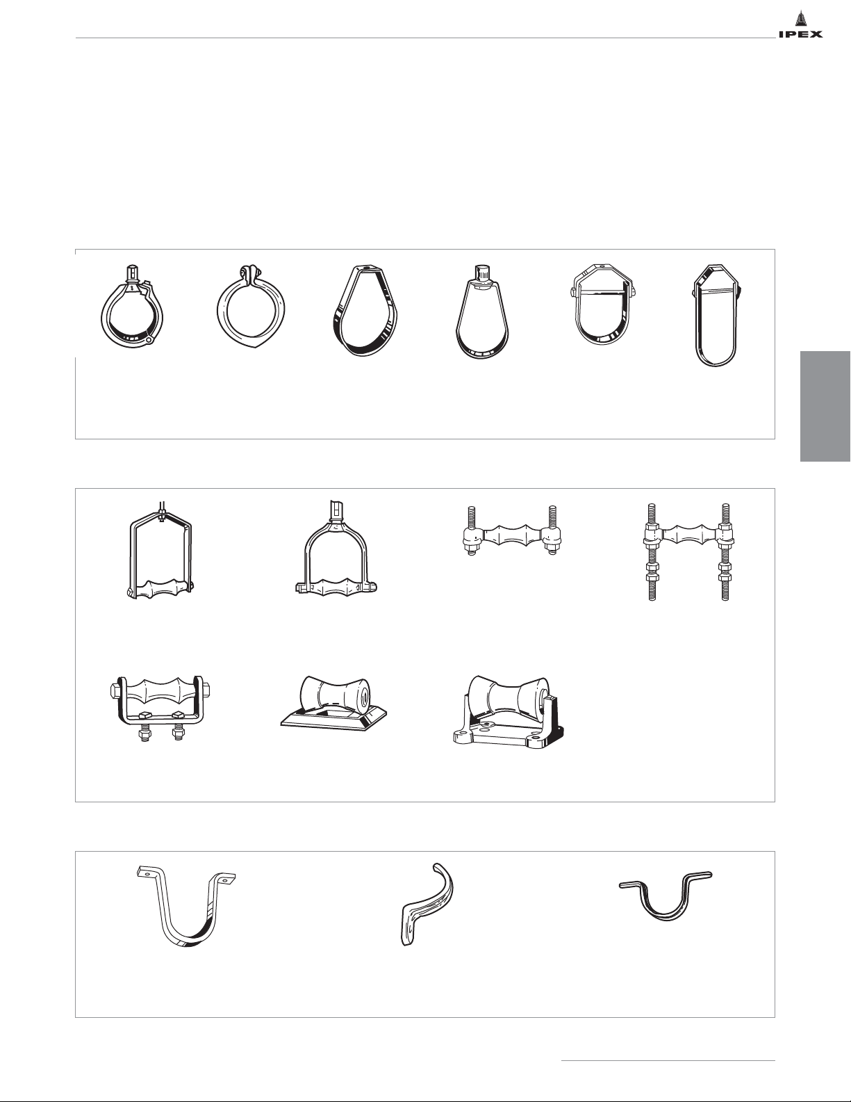
DESIGN
CONSIDERATIONS
47
IPEX Acid Waste Piping Systems
Recommended Pipe Hangers
Clamps used as anchors (such as U-bolts, etc.), if over-tightened, can produce a point-of-load stress on the pipe. This can
result in cracking or premature burst failure. If U-bolts must be used, then a metal shield should be placed between the
U-bolt and pipe surface. When anchoring plastic pipe, it is always desirable to spread the load over a wide area of contact.
Pipe Rings
Adj. Swivel Ring
Split Ring type
3/4" to 8" pipe
Split Ring
3/8" - 8" pipe
Adj. Ring
1/2" - 8" pipe
Adj. Swivel Ring
1/2" - 8" pipe
Adj. Clevis -
Standard
1/2" - 30" pipe
Adj. Clevis For
Insulated Lines
3/4" - 12" pipe
Pipe Rolls
Adj. Steel Yoke Pipe Roll
2-1/2" - 20" pipe
Adj. Swivel Pipe Roll
2-1/2" - 12" pipe
Single Pipe Roll
1" - 30" pipe
Adj. Pipe Roll Support
1" - 30" pipe
Roller Chair
2" - 12" pipe
Pipe Roll and Plate
2" - 24" pipe
Pipe Roll Stand Complete
2" - 42" pipe
Pipe Straps and Hooks
Wrought Strap Short
1/2" - 4" pipe
One Hole Clamp
3/8" - 4" pipe
Tin Strap
1/2" - 2" pipe
Page 55
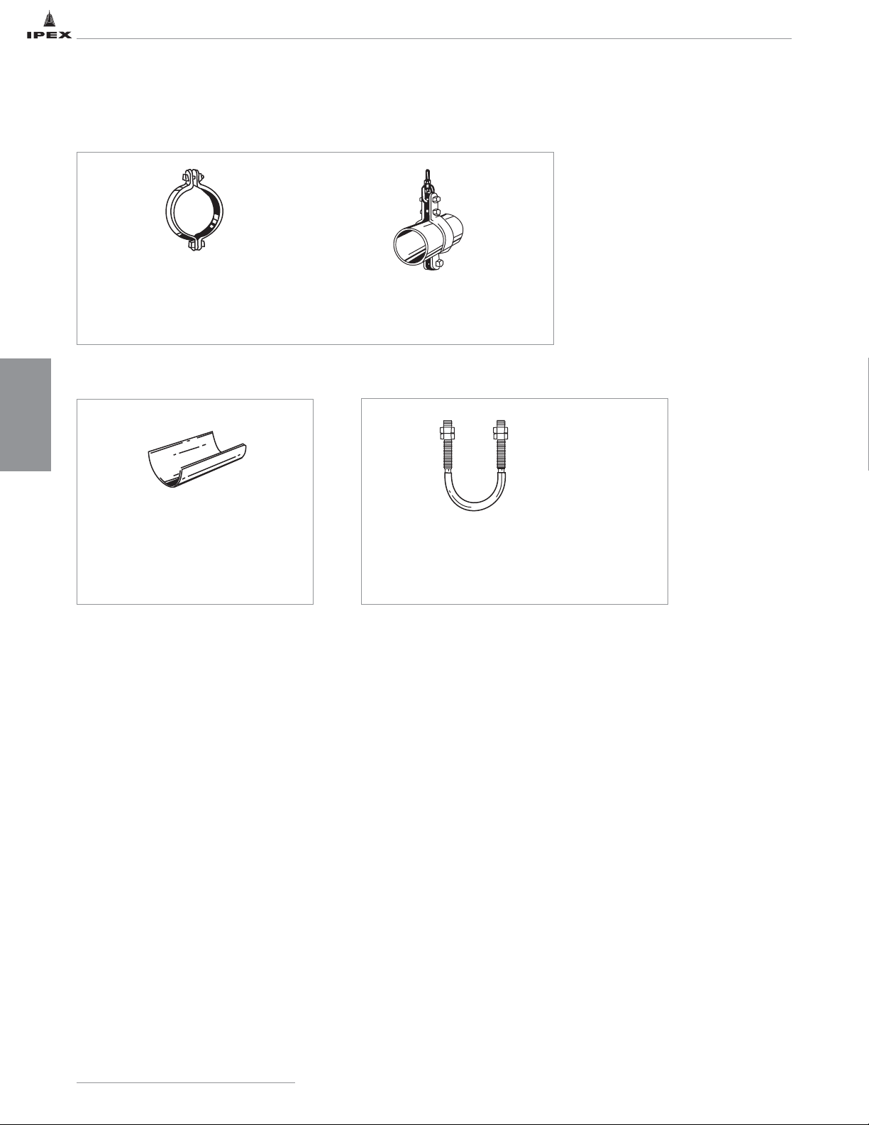
Pipe Clamps
Pipe Clamp Medium
1/2" - 24" pipe
Double Bolt Pipe Clamp
3/4" - 36" pipe
Pipe Covering
Insulation Protection Shield
1/2" - 24" pipe
Bolt
U Bolt*
Standard: 1/2" - 30" pipe
Light Weight: 1/2" - 10" pipe
*Also available
plastic coated.
IPEX Acid Waste Piping Systems
48
DESIGN
CONSIDERATIONS
Page 56

HANDLING AND STORAGE
Thermoplastics are strong, lightweight materials, about one
fifth the weight of steel or cast iron. Piping made of this
material is easily handled and, as a result, there is a
tendency for it to be thrown about on the jobsite. Care should
be taken in handling and storage to prevent damage to the
pipe. Some general guidelines are as follows:
• If stored outdoors, best practice dictates that Enfield and
Labline pipe and fittings be covered with a protective
cover that is well ventilated. Ideally, pipe and fittings
should always be stored inside a building or materials
storage trailer.
• Make sure the pipe is adequately supported at all times.
Avoid stacking pipe in large piles, since the pipe at the
bottom may incur high loads. Store on level support to
prevent sagging or bending.
• For long-term storage, use pipe racks to support the pipe
continuously along its length. If this is not possible,
supports of at least 3 in. bearing width, at spacings not
greater than 3 ft centers, are recommended. Pipe should
not be stored more than seven layers high. Sharp corners
on metal racks should be avoided.
• Pipe is often supplied in crates. Take care when
unloading crates, and avoid using metal slings or wire
ropes. Crates may be stacked four high in the field.
• Exercise care while handling pipe. Damage may occur if
pipe collides with sharp corners, or is dropped.
• Drainage applications require that the pipe lengths be
installed with the required amount of pitch, or fall, to
achieve proper drainage flow. Storing pipe in direct
sunlight may result in development of bowing or curving
within pipe lengths. Bowing or curving may impede the
ability to correctly pitch the pipe to achieve proper
drainage flow.
• Extra care should be taken when unloading and handling
pipe in cold weather. The impact strenght for FRPP,
NFRPP and FR-PVDF is reduced at lower temperatures.
Dropping pipe from a truck or forklift may cause damage.
Methods and techniques normally used in warm weather
may not be acceptable at lower temperature range.
IPEX Acid Waste Piping Systems
49
DESIGN
CONSIDERATIONS
Prolonged Outdoor Exposure
Prolonged exposure of Enfield and labline FRPP and NFRPP
to the direct rays of the sun will not damage the pipe
material. However, some mild discoloration may take place in
the form of a milky film on the exposed surfaces. This
change in color merely indicates that there has been a
harmless chemical transformation at the surface of the pipe.
A small reduction in impact strength could occur at the
discolored surfaces; but it is of a very small order and can be
removed during the joining process.
Unlike many other thermoplastic materials, FR-PVDF is not
susceptible to degradation due to UV exposure. Therefore,
prolonged exposure of FR-PVDF pipe to the direct rays of the
sun will not damage the pipe. For purposes of cleanliness
however, it is good practice to keep pipe and fittings under a
well ventilated protective cover when stored outdoors.
Painting
PP pipe and fittings can be easily protected from ultraviolet
oxidation by painting with a heavily pigmented, exterior
water-based latex paint. The color of the paint is not
important; the pigment merely acts as an ultraviolet screen
and prevents sunlight discoloration. White or some other light
color is recommended since it helps reduce pipe temperature.
The latex paint must be thickly applied as an opaque coating
on pipe and fittings that have been cleaned well, very lightly
sanded, and primed with a latex base primer.
Page 57
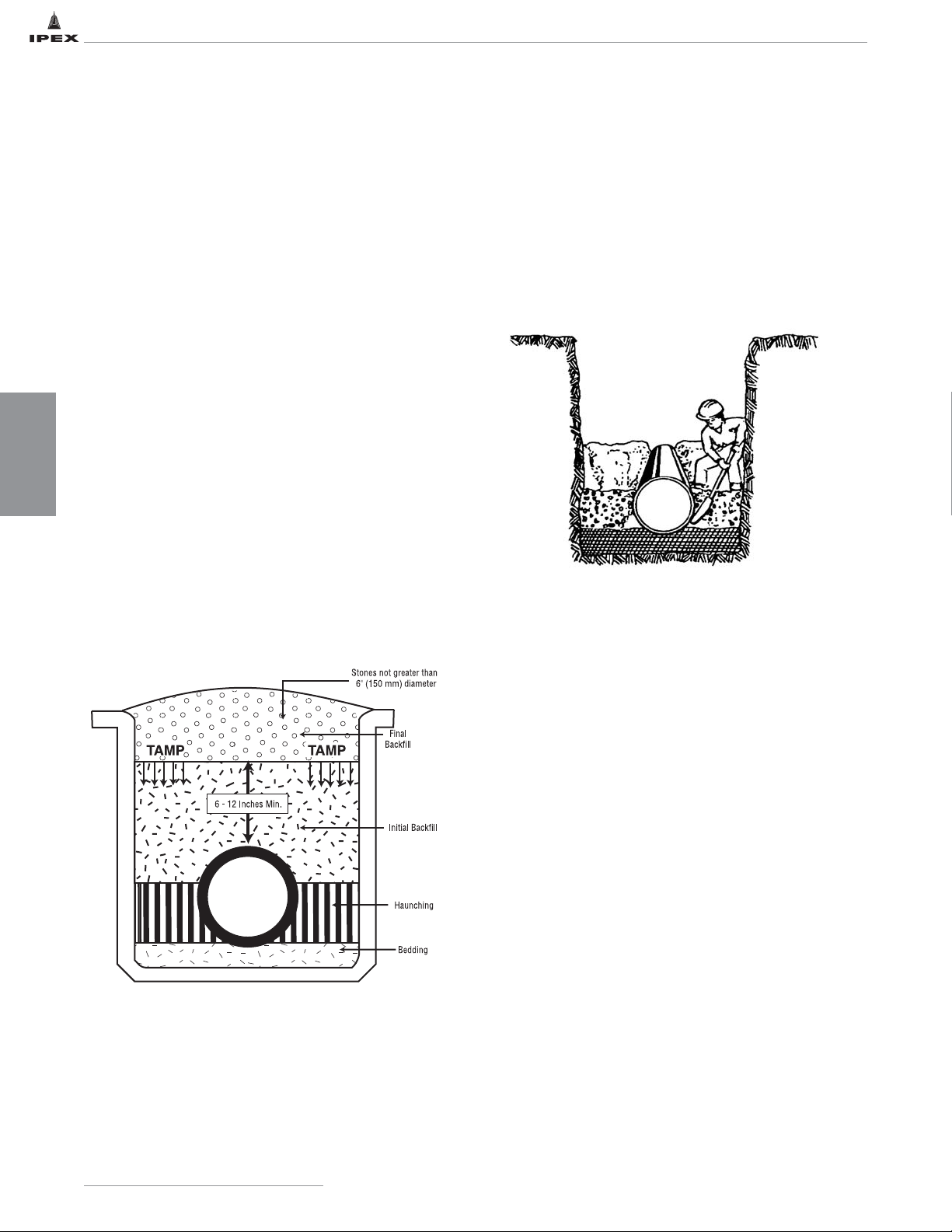
BELOW GROUND INSTALLATION
Trenching
The trench bottom should be continuous, relatively smooth,
and free of rocks. Where ledge rock, hardpan or boulders are
encountered, the trench bottom should be padded using a
minimum of 4" of tamped earth or sand beneath the pipe.
Trenches under slabs should allow for a 12" depth of cover
over the pipe. In open locations, the trench depth should
allow for the top of the pipe to be at least 12" below the
maximum expected depth of frost penetration.
Pipe installed beneath surfaces which could be subjected to
extremely heavy static weight or constant traffic should be
shielded within a metal or concrete casing.
Backfilling
Fill piping with water of an ambient soil temperature and
check joints. Cover to a depth of 6" to 8" with dirt which is
free from rocks, debris or particles larger than
1
/2". At this
point in the proceedings, all joints should remain exposed for
inspection. Leave piping to settle and normalize
dimensionally, then check all joints for tightness and tamp
soil layer which will act as a cushion for subsequent backfill.
While tamping, see that pipe alignment, both vertical and
horizontal, is not disturbed.
Compacting the Backfill
Compact the haunching, initial backfill and final backfill
using manual equipment in accordance with the job
drawings. Observe the following precautions.
1. When a “self-compacting” material is used, such as
crushed stone, ensure that the material does not arch or
bridge beneath the haunch of the pipe. Remove such
voids with the tip of a spade.
2. When compacting the material underneath and at either
side of the pipe do not allow the tool or the machine to
strike the pipe.
3. When compaction in excess of 85% standard proctor
density is required in the haunching area ensure that the
compacting effort does not dislodge the pipe from the
correct grade. If the compacting effort dislodges the pipe,
re-lay the pipe to the correct grade.
4. It is not necessary to compact the initial backfill directly
over the top of the pipe for the sake of the pipe’s
structural strength. However, it may be necessary for the
sake of building/roadway integrity.
When laying long runs of piping in elevated air temperatures,
it is advisable to begin working from a fixed point
__
such as
the entry or exit from a building, and work away from that
point, testing and backfilling in accordance with preceding
paragraphs. This procedure should then allow the piping to
assume soil temperature progressively as work proceeds.
Final Backfill
Thoroughly test the system for leaks. When satisfied, cover
all joints with soil and finally proceed with the remainder of
backfill. Large sharp rocks which could penetrate the initial
layer and damage the pipe should be removed prior to the
final backfill.
IPEX Acid Waste Piping Systems
50
DESIGN
CONSIDERATIONS
Page 58
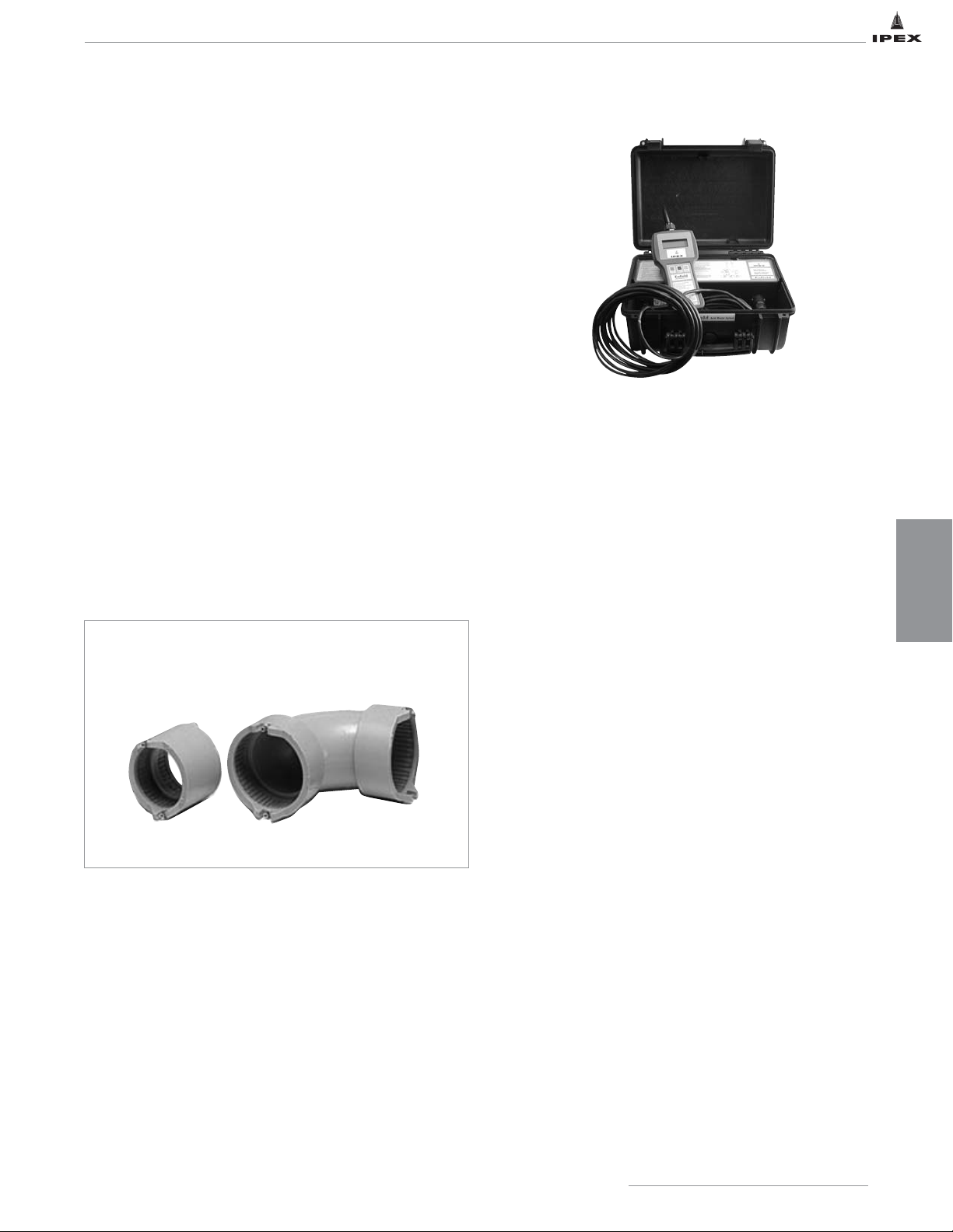
Standard Enfield Electrofusion
To ensure professional installation, make sure all installers have
undergone training by IPEX in the correct handling, joining and
installation methods of IPEX thermoplastic products.
Enfield fittings are manufactured with an integral resistance
wire, molded in place using a proprietary manufacturing
process. The wire is electrically heated by means of a
microprocessor controlled Enfusion Control Unit. This results
in fusion and bonding of the pipe to the fitting. A permanent
joint is achieved within minutes.
The Enfield joint achieves the optimum level of
performance where it matters most __at the fitting socket
/ pipe spigot interface. There is a controlled fit, controlled
temperature and controlled time. All of this is achieved by
means of the Enfusion Control Unit, which ensures proper
electrical connections, joint timing and input/output
current levels. The combination of these features provides
both simplicity of jointing and perfect control. The result
is an unparalleled level of joint repeatability.
Job Site Precautions
1. Do not use unit in a gaseous environment as there is a
RISK OF EXPLOSION.
2. The unit is a Class 1 device, and must be used with a
grounded power supply.
3. Only use a hydrostatic test on the system.
TESTING WITH AIR IS DANGEROUS FOR A POLYPROPYLENE
(PP) ACID WASTE SYSTEM.
4. Store pipe and fittings out of direct sunlight. If material
is stored outside, it should be covered with a light
colored opaque tarp. If the ambient temperature exceeds
100ºF (37ºC), make provisions to allow air to circulate
beneath the tarp.
5. Handle the Enfusion Hand Held machine carefully.
DO NOT TAMPER! Call your IPEX representative for
machine service.
6. DO NOT MIX BRANDS. Good joints can only be made
using Enfield pipe, fittings and clamps. Mixing brands
voids all warranties.
7. Software version V1.19 on the handheld Enfusion
control unit will automatically adjust the fusion cycle
time to the ambient temperature. The pipe, fittings and
Enfusion control unit processor must all be allowed to
acclimatise to the same temperature.
SECTION FOUR: INSTALLATION
ENFUSION HAND HELD CONTROL UNIT
The IPEX Enfusion hand held control unit is supplied with a 33 ft
(10m) output lead and a hand held control unit weighing approximately
2.2lbs (1kg). The hand held unit, along with the fusion processor, are
stored in a durable plastic case for easy handling and transport.
Introduction
Proper installation is key to producing a reliable and long lasting acid
waste system. If the installation is not done correctly, the system will
not perform well and may actually fail.
IPEX Acid Waste Piping Systems
51
INSTALLATION
Page 59
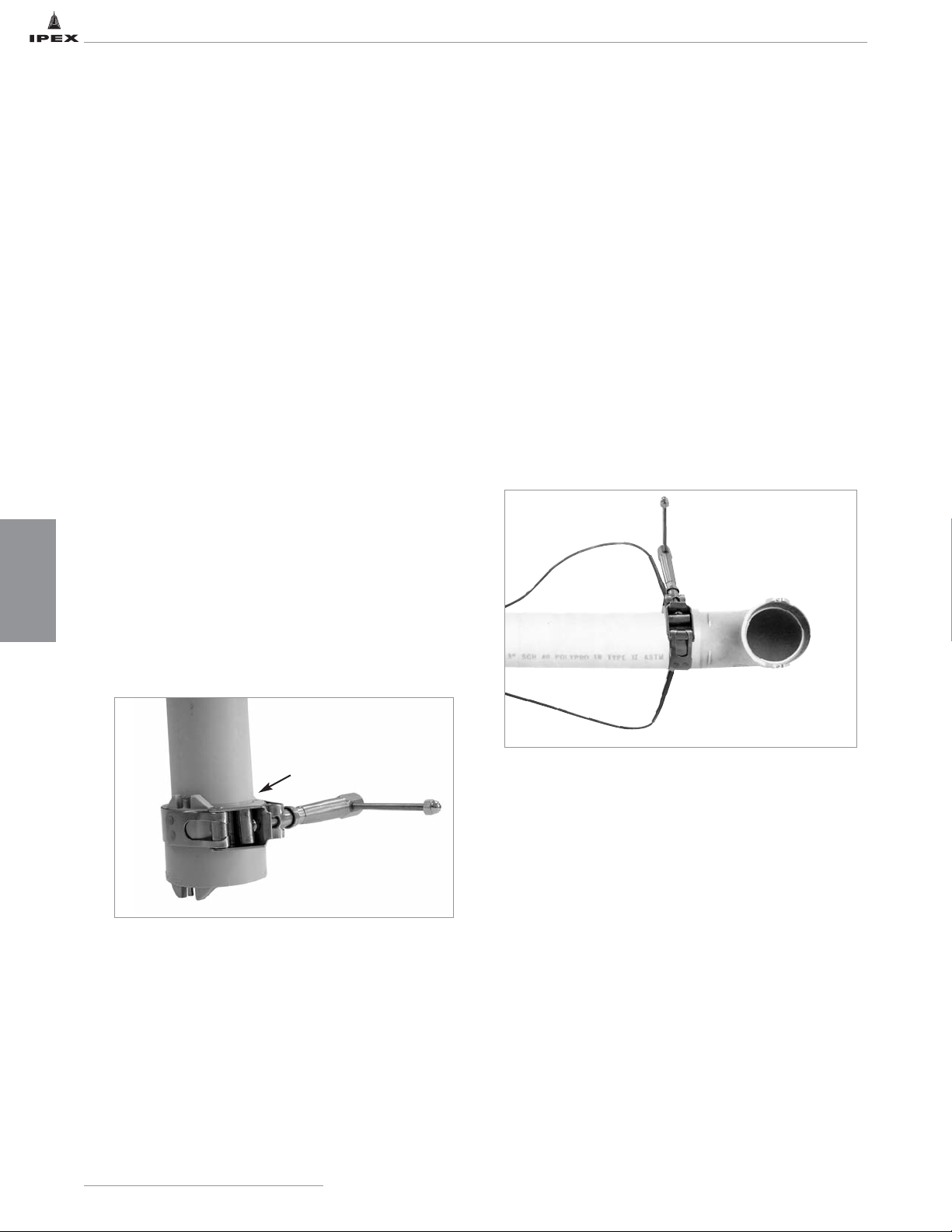
Before making the Enfield joint, it is important to check with an RMS meter, that the power source is providing between 96
and 162 volts @ 40 to 70 cycles with 11-amp capacity. The Enfusion hand held control unit provides for normal power
variations, however generators should be checked to assure the correct output is always being provided.
1. Completely unwind all cables from the Enfusion hand
held machine's case before use.
2. Using a suitable mitre saw/chop saw or tube cutter
designed for plastic, cut the pipe square making sure to
remove all burrs and loose material. Do not chamfer.
3. Using 60-grit emery cloth, prepare the end of the pipe
by removing dirt and oil (important to obtain a good
bonding surface) and roughing up an area equal to 1.5
times the fitting's socket depth. Clean the roughed up
area with ethyl or isopropyl alcohol to ensure complete
removal of grease and residue. Once treated do not
handle this area of the pipe or allow it to get dirty.
4. Insert the pipe all the way to the stop at the bottom of
the socket of the fitting.
5. Decide whether single or multiple joints are being made.
In case of multiple joints consult the “Multiple Joints
Fusion” section that follows for cable connections and
maximum allowable number of simultaneous joints.
6. Loosely fit IPEX-supplied clamp(s) only over the hub(s)
of the socket(s) to be fused (Figure 1).
Note: The clamp should be positioned flush with the
edge of the fitting. The clamp must be tightened
sufficiently to prevent the pipe from rotating inside
the fitting. Wheel handle clamps should not be used.
7. Tighten the clamp(s). A tight clamp is essential to the
quality of the joint. It should not be possible to rotate
the pipe inside the fitting socket when the clamp is
fully tightened.
8. Turn the Enfusion hand held control unit on and observe
the copyright message and the software version being
displayed as the machine runs a self-diagnostic test.
9. Following the “CONNECT LEADS AND FITTINGS”
instruction on the display, connect the output leads
(Figure 2). If required, connect link cable for
multiple fusions.
FIGURE 1
Edge of the Fitting
FIGURE 2
IPEX Acid Waste Piping Systems
52
INSTALLATION
INSTALLATION
Page 60
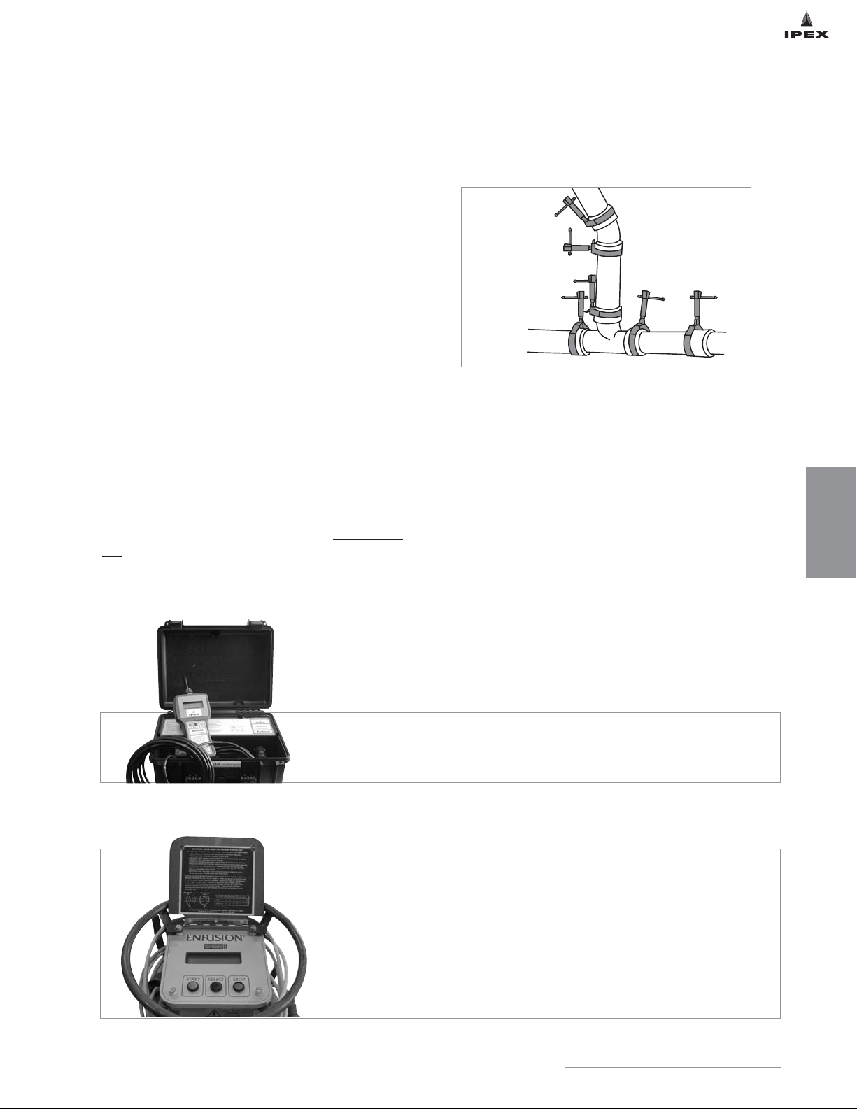
IPEX has developed a revision to its fusion machine software.
Your machine will display the software version upon start up,
the most recent version being V1.19 (2014). This revision
removes the need to select a size range, and automatically
adjusts the fusion time based on ambient temperature. Allow
time for the machine pipe and couplings to acclimatise.
10.
With software UPDATE V1.19 (2014)
Once the leads are connected and you are ready to begin
the fusion process. The machine will automatically
check to ensure a connection is present and measure
the ambient air temperature to set the fusion time.
Without software UPDATE
Machines that have NOT been updated will require you
to “SELECT SIZE”. IPEX recommends the use of the
3" to 12" size range for all
fittings regardless of size.
(example: 1.5" fittings should use the 3" to 12"
selection)
11. To begin the fusion cycle press START. Time will begin
to count down to zero.
12. Upon completion of the fusion cycle an audible alarm
will sound and the message “WELD COMPLETE
DISCONNECT LEADS” will be displayed. A 30 second
rest period must be observed to allow the joint(s) to cool
efore disconnecting the leads. The Enfusion machine
will automatically reset, ready for the next operation.
IPEX Acid Waste Piping Systems
53
INSTALLATION
13. Allow five additional minutes before removing the
clamps so that the joint can sufficiently cool and
properly cure.
Note: If leads are accidentally disconnected during the fusion
process "Reconnect Lead & Press Start" will appear and a
120 second countdown will begin on the Enfusion hand held
control unit. Reconnect leads and press START to continue
the fusion cycle fusion.
If leads are reconnected during the countdown, the fusion
machine will automatically assess how long the fusion cycle
must be depending on how long the leads have been
disconnected. If the leads are not reconnected during the
countdown the machine will sound an audible alarm and
restart the fusion cycle time. Prior to re-fusing, 1-1/2" – 3"
fittings should cool for 5 minutes and 4" – 12" fittings
should cool for 7 minutes. The Enfusion Control Unit should
be reset by shutting it off and following instructions from
step 8 onwards.
FIGURE 3
L2600 (Old Style Machine) Software UPDATE
This machine cannot be reprogrammed with the software update mentioned
above. Due to the age of the machine and its components IPEX can no
longer support updates to the machine’s components or software.
Note: It is recommended that you replace these (L2600) machines with
newer models. Until such time that a machine can be purchased, all joints
regardless of size must be fused using the 4" size selection. Contact your
local IPEX representative.
V1.19 Enfusion Hand Held Control Unit
To obtain V1.19 on your hand held, please contact an IPEX representative.
Page 61
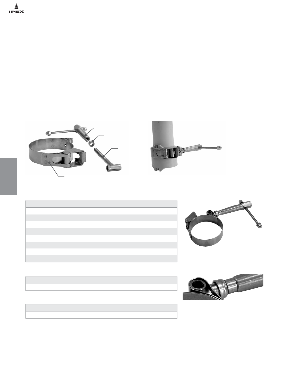
SS T-Bar Handle Joint Hub Clamp for use during fusion of Enfield®electrofusion joints
• Redesigned T-bar handle for greater ease of use. (more efficient transfer of torque)
• Reduces the torque required to tighten the fitting on the pipe.
• Oil impregnated bushing reduces friction and resulting worker fatigue from repetitive tightening.
• Easy replacement of friction reducing bushings.
• Part of the IPEX Enfield
®
corrosive waste system of pipe, fittings and accessories.
• Replacement oil impregnated bushings available.
• Enfield®components should only be joined using Enfield®Electrofusion Control Units.
• IPEX components are dimensionally matched; do not install system of mixed brands without our express written consent.
Clamp Band
T-Bar
Bushing
Threaded Rod
Note: The clamp should be positioned
flush with the edge of the fitting. The
clamp must be tightened sufficiently to
prevent the pipe from rotating inside the
fitting.
This procedure is necessary to complete
a proper joint. The clamp may hang
slightly over the end of the hub on
certain fittings. If this occurs, please
ensure that the fusion leads do not come
into contact with the clamp.
Enfield
®
Electrofusion Joint Hub Clamp with New SS T-Bar Handle
Replacement Oil Impregnated Brass Bushings – Replace as Needed
Stainless Steel T-Bar Handle for Hub Clamp*
* To retrofit previously available black
plastic wheel handles supplied on
Enfield
®
Hub Clamps
Size (in) Product Codes Significant No.
1-1/2 257254 L26101
2 257256 L26102
3 257257 L26103
4 257258 L26104
6 257259 L26106
8 257260 L26108
10 257255 L261010
12 257262 L261012
Clamp Size (in) Product Code Significant No.
1-1/2 - 12 257094 L2610B
Clamp Size (in) Product Code Significant No.
1-1/2 - 12 257125 L2610T
IPEX Acid Waste Piping Systems
54
INSTALLATION
Page 62
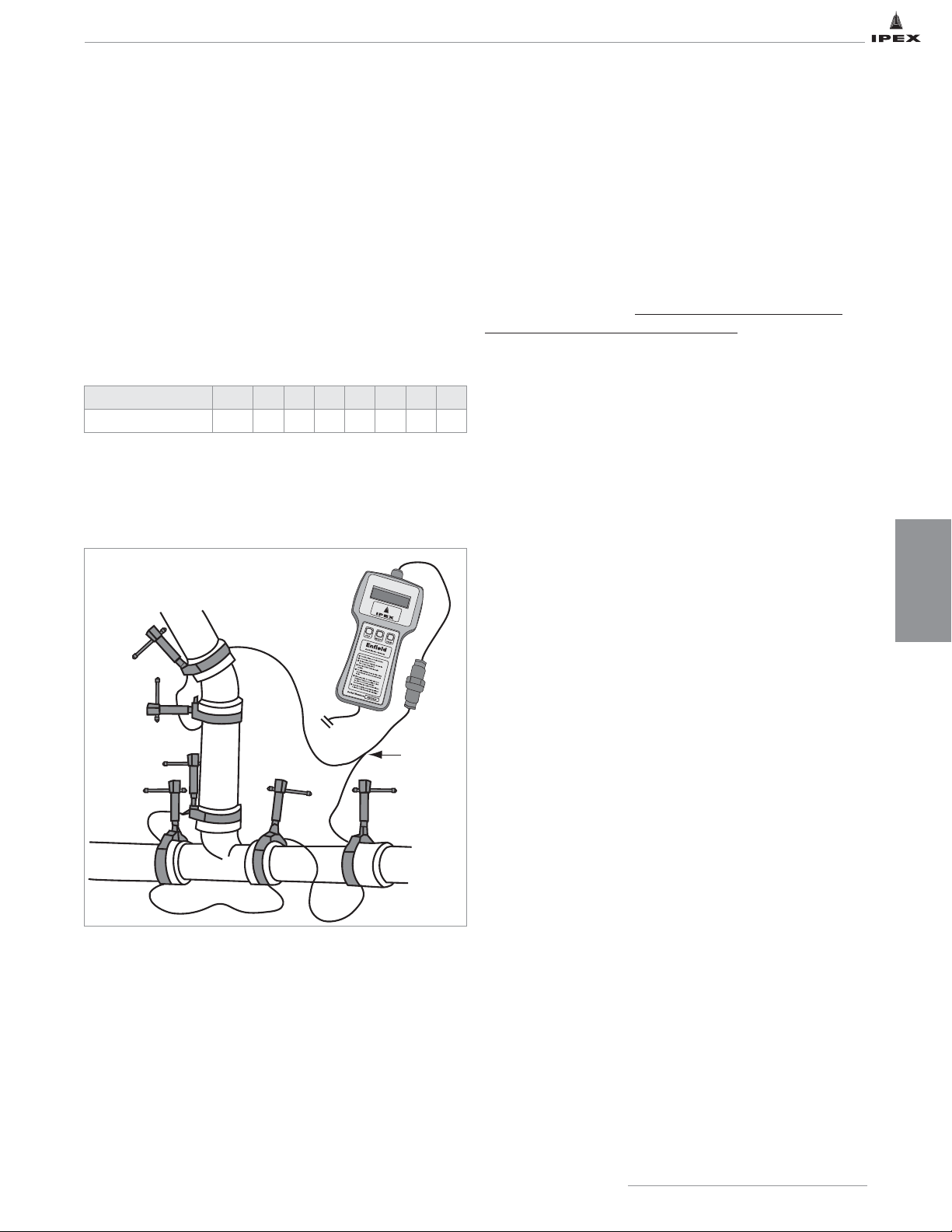
Enfield Fusion Times
With the update to the fusion machine software (V1.19,
2014), fusion times are now standard across all sizes.
Fusion times will however vary based on the ambient air
temperature. As the temperature goes up the fusion time will
go down, conversely, as the temperature goes down the time
will go up. As a reference: at 73
o
F (23oC) the fusion time is
125 seconds.
The chart indicates the number of joints for each side that
can be fused at one time.
Attach the connector leads and link cable leads to fitting
terminals as shown in Figure 4.
The link cables should be
connected in series.
Follow the fusion procedure, as outlined
in steps 1-13, to complete the multiple fusion.
Multiple Joints Across Different Sizes
With the update to the fusion machine software
(V1.19, 2014), fusion times are now standard across all
sizes, as such the combination of different size fittings
that can be fused at the same time is much less restricted.
Any number of fittings or combination of sizes is now
possible, provided that when you add the joint diameter
sizes up – the total does not exceed 12.
Example A
1 x 8
"
and 1 x 4" = 12.
Therefore one 8" fusion joint and one 4" fusion joint could be
done at the same time.
Example B
1 x 8" and 2 x 3" = 14.
Therefore one 8" fusion joint and two 3" fusion joints could
not be done at the same time.
Example C
2 x 1.5" and 2 x 4" = 11.
Therefore two 1.5" fusion joints and two 4" fusion joints
could be done at the same time.
Example D
1 x 2" and 2 x 6" = 14.
Therefore one 2" fusion joint and two 6" fusion joints could
not be done at the same time.
Maximum Allowable Joints Per Size
Pipe Size (inches) 1-1/2 2 3 4 6 8 10 12
Max # of joints 8 6 4 3 2 1 1 1
FIGURE 4
IPEX Acid Waste Piping Systems
55
MULTIPLE JOINT FUSION
INSTALLATION
S
S
R
R
Note: Each joint being fused must have an IPEX T-Bar clamp
flush with the other edge of the socket as shown previously
in Figure 1.
Enfusion
Hand Held
Control Unit
Connector
Cable
Page 63

IPEX Acid Waste Piping Systems
56
NOTES
Page 64

FAULT CODE ANALYSIS
FAULT NUMBER AND CODE ACTION
0 WELD OK No Fault, weld completed OK.
1
STUCK BUTTON ON
START UP
This fault shows when the power is first switched on. Either the Stop, Start, or a keypad button is stuck in.
Free the button to clear the fault.
2
OUTPUT FAULT BEFORE
WELD START
This fault shows when the power is first switched on. The unit will check the output relay to make sure it is
working correctly. If this fault happens, then the internal power relays have pulled in to the closed position.
Return unit for service.
4 NO CALIBRATION
This fault happens when the unit has no calibration. This normally not show, and it the unit has been
calibrated, would be caused by a fault with the internal memory. Return unit for service.
7
AMBIENT TEMPERATURE
TOO HIGH
If this ambient is measured at over +50ºC (122ºF) then this fault will show.
8
AMBIENT TEMPERATURE
TOO LOW
If the ambient is measured at below -20ºC (-4ºF) then this fault will show.
9
AMBIENT TEMPERATURE
FAU LT
This fault is shown if the temperature is measured as less than -100ºC (-148ºF) or more than +100ºC
(212ºF). This effectively means a short circuit or open circuit sensor.
10
LOW SUPPLY
FREQUENCY <40HZ
The unit has detected that the supply frequency is below 40 Hz. This will normally be caused by a poor
quality generator. If this fault happens, then check the supply or change the generator.
11
HIGH SUPPLY
FREQUENCY >70HZ
The unit has detected that the supply frequency is above 70 Hz. This will normally be caused by a poor
quality generator. If this fault happens, then check the supply or change the generator.
12
HI SUPPLY VOLTAGE
>140V
The unit has detected that the supply voltage is more than 140 volts. Check the supply voltage and if
necessary use a different generator.
13
LOW SUPPLY VOLTAGE
<95V
This vault can be caused by a few problems. It could be that the generator is running slowly and so the
supply voltage is low. Try speeding the generator up or use a different generator.
It could also be caused by a generator that is too small. If a large fitting is welded, then a large amount of
power will be needed from the generator. If it can not supply this power, then it will stall and the voltage will
drop away. Check that the generator is the correct size, if needs be try another generator.
It could be caused by the use of long extension leads. If a large fitting is welded, then a high current will be
taken from the supply. If extension leads are used, three will be a volts drop down the lead making the unit
sense a low supply voltage. Try not to use extension leads with the unit. If you have to, then use just 30 feet
of cable, the same size fitted to the unit.
14
RELAY FAILED TO LATCH
ON WELD START
This fault could happen when the start button is pressed. If the main power relays do not operate correctly,
then this fault will be shown. Return unit for service.
20
WELDING CURRENT
EXCESSIVE (>150%)
This fault will happen if the welding current is more than 50% high for more than 0.3 seconds. this fault is
normally caused by a fault with the unit, a short circuit triac. Return unit for service.
21
WELDING CURRENT
HIGH (>125%)
This fault will happen if the welding current is more than 25% high for more than 1 second. This fault is
normally caused by a fault within the unit, a short circuit triac. Return unit for service.
22
WELDING CURRENT
HIGH (>112.5%)
This fault will happen if the welding current is more than 6.25% high for more than 2 seconds. this fault will
normally be caused by a poor quality generator with the supply voltage fluctuating. Try a different generator.
23
WELDING CURRENT
HIGH (>106.25%)
This fault will happen if the welding current is more than 6.25% high for more than 2 seconds. this fault will
normally be caused by a poor quality generator with the supply voltage fluctuating. Try a different generator.
24
WELDING CURRENT
HIGH (>101.5%)
This fault will happen if the welding current is more than 1.5% high for more than 3 seconds. This fault will
normally be caused by a poor quality generator with the supply voltage fluctuating. Try a different generator.
25
USER STOP BUTTON
PRESSED
The operator has pressed the stop button.
26 RELAY UNLATCHED
During welding, if the main power relay disconnects, then this fault will be shown. It could be caused by the
unit being knocked or a temporary dip in the power supply.
27 FITTING OPEN CIRCUIT
This fault is shown if the output lead disconnects from the fitting while welding. Follow the guidelines from
this manual to reconnect the lead and try welding again.
28
WELDING CURRENT LOW
(<98.5%)
This fault will happen if the welding current is more than 1.5% low for more than 3 seconds. This can be
caused by a generator that is not big enough to supply the required power to the fitting. Check the size of the
generator and if needs be try another generator. It can also be caused by using long extension leads with the
unit. It is recommended that only 30 feet of extension are used, and the cable should be the same thickness
as the input lead on the unit.
29
WELDING CURRENT LOW
(<50%)
This fault will happen if the welding current is more than 50% low for more than 1 second. It can be caused
by a faulty fitting. Try another fitting. If this doesn’t clear the fault then there is a problem inside the unit.
Return unit for service.
127 POWER OFF FAILURE If the power is turned off while the unit is welding, this fault will be recorded to the catalogue.
IPEX Acid Waste Piping Systems
57
INSTALLATION
Page 65
Repair Information
There are no user serviceable parts inside the welding unit. If
an internal fault happens with the unit then it must be
returned to IPEX for repair. Please contact your local IPEX
distributor for instructions on the proper return of your
enfusion unit.
Specification
Operating Mode Enield Automatic
Operating Language English
Operating Temperature 0ºF to 120ºF
Input Voltage
120 V ac
95V to 140V
Input Current 10.5A
Input Frequency
50 Hz
40 Hz to 70 HJz
Input Power 100 VA to 1250 VA
Output Current 18 A ac true rms
Output Voltage 3 V to 50 V ac true rem
Output Power 50 W to 900 W
Output Stability +/-1.5%
Welding Temperature 0ºF to 120ºF
Power Factor 0.72
Unit Weight 33 lb
Hand Held Weight 2.2 lb
Size 15.7" x 12.6" x 6.3"
Environmental Protection IP65
Lead Length (to power case) 16.5 ft
Lead Length (to hand held unit) 33 ft
Lead Length (to fitting) 6.6 ft
IPEX Acid Waste Piping Systems
58
INSTALLATION
Page 66
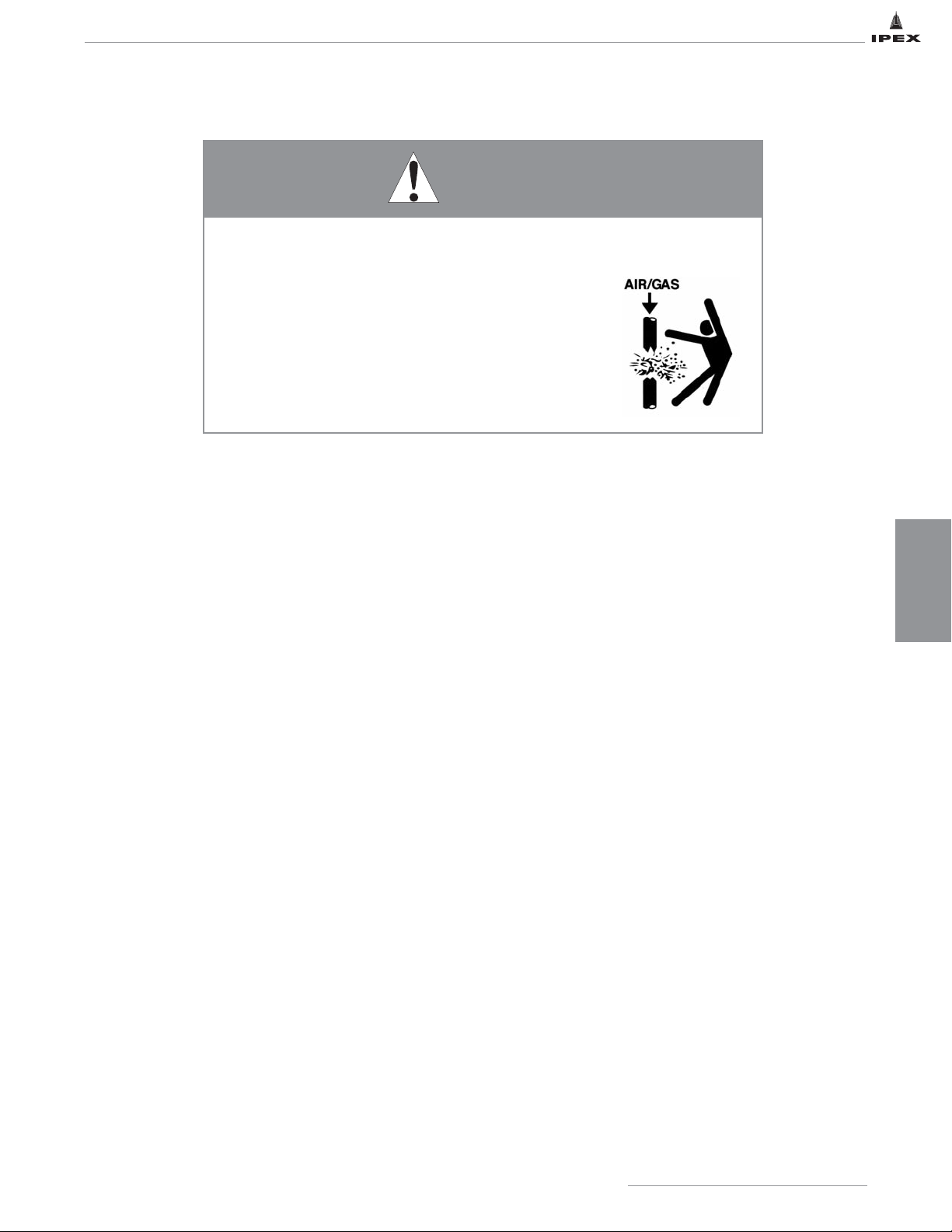
ENFIELD TESTING
The purpose of a site pressure test is to establish that all joints have been correctly made.
Hydrostatically (water) test in accordance with local plumbing code or with authority having jurisdiction; but not
exceeding a maximum of 10 ft of head pressure. After making the first 20 or 30 joints, it is highly recommended that a
test be applied to ensure that the joint-making technique is satisfactory. If a leak is discovered, follow the appropriate
procedure below.
Hydrostatic testing of the joints can be performed 10 minutes after the final joint has been completed. The low pressure
testing procedure detailed below should be strictly followed.
1. Fully inspect the installed piping for evidence of
mechanical abuse and suspect joints.
2. Split the system into convenient test sections, not
exceeding 1,000 feet. The piping should be capped off
with an expandable plug at the end of the pipe section
to be tested.
3. Prior to starting the test in below grade applications,
straight lengths of pipe should be backfilled between
fittings that are tested.
4. Slowly fill the pipe section with water, taking care to
evaluate all trapped air in the process. Use air release
valves in any high spots in the system. Do not pressurize
at this stage.
5. Leave the pipe for at least one hour to allow an
equilibrium temperature to be achieved.
6. Visually check the system for leaks.
7. Pressurize the system to a suggested maximum of 10
feet of head by means of a standard 10' standing water
test using a 10' vertical riser, or a low-pressure hand
pump.
8. Leave the line at 10 feet of head for a period of 2 hours,
during which time the water level should not change
(standing water test), nor should the pressure gauge
reading change (hand pump test).
9. If there is a significant drop in pressure, or extended
times are required to achieve the desired pressure, either
joint leakage has occurred or air is still entrapped in the
line. In this event inspect for joint leaks. If none are
found, check for entrapped air – these air pockets must
be removed prior to continuing the test.
10. If joints are found to be leaking, the system must be
fully drained and the joints repaired. Dry, or marginally
fused Enfield joints can be re-fused by following steps
5 through 13 in the Standard Enfield Electrofusion
Installation procedure. To remove moisture from the
joint, use the drying cycle.
• To dry the Enfield joint jusing the handheld Enfusion
machine with software V1.17 or earlier, the drying
cycle can be accessed by starting and stopping a
regular fusion cycle within 2 seconds.
• To dry the Enfield joint using the handheld Enfusion
machine with software V1.19, users need to connect
the leads and fittings. The machine will prompt the
user to “PRESS START”. The user needs to press the
“SELECT” button and then “START” button
immediately after. The drying cycle will appear with a
45 second count down.
• Allow the joint to cool.
• NEVER use compressed air or gas in Enfield, Labline, or
Plenumline pipes, fittings, or accessories.
• NEVER test Enfield, Labline, or Plenumline systems with
compressed air or gas, or air-over-water boosters.
• ONLY use Enfield, Labline, or Plenumline systems for
approved chemicals.
Use of compressed air or gas in PP or PVDF pipe and fittings can result in
explosive failures and cause severe injury or death.
WARNING
IPEX Acid Waste Piping Systems
59
INSTALLATION
Page 67

INSTALLATION
ENFIELD TESTING
60
IPEX Acid Waste Piping Systems
• Now re-fuse using the correct Enfusion machine
settings for the size of pipe being joined following
steps 5-13 of the Standard Enfield Electrofusion
Installation procedure.
• Should any of the re-welded fitting(s) fail the second
hydro-test, the leaking joint(s) can be back-welded
with a hot-air gun and welding rod. Should the
back-welded joint(s) fail a third hydro-test, they will
need to be cut out of the system and substituted with
new fittings.
• If a joint has be to cut out and replaced, the
procedure for pipe modification detailed in this
manual should be strictly followed.
11. Repeat the 10 feet head test after repairing any
leaking joints, following the procedure described above.
Page 68
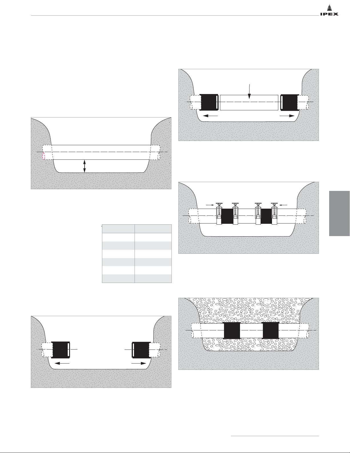
INSTALLATION
61
IPEX Acid Waste Piping Systems
ENFIELD PIPE REPAIR
In the unlikely event of a leak, Enfield piping systems can be
easily repaired.
Procedure:
1. Determine exact location of leak. For below grade
installation excavate the ground near the pipe leak, taking
care not to cause damage to the piping system in the
process. Hand digging is suggested. The ground should be
excavated to a depth of at least 6" below the bottom of the
pipe.
2. Measure the length of pipe to be removed then cut
completely and SQUARELY through the pipe sections.
Remove the damaged section of pipe.
3. Mark a pencil line on the
end of both open ends of
the pipe to locate the
joining position for the
repair couplings. The
pencil line should be at
the following distance
from the pipe ends.
4. Slide one repair coupling over the exposed spigots of the
two pipe sections.
5. Measure, prepare and insert a pipe spool piece into the
line to be repaired.
6. Slide the repair couplings into position between the pencil
lines previously drawn on the pipe ends. Place the clamps
over the repair couplings. Tighten the clamps and fuse the
joints using the correct Enfusion machine settings.
7. Remove the hub clamps after allowing the joint to cool for
10 minutes.
8. If buried below ground, surround the pipe with pea gravel,
then backfill and consolidate.
6"
Pipe spool piece
Pipe Size (in) Pencil Mark (in)
1-1/2 3/4
2 1
3 1-3/8
4 1-1/2
6 2
8 2-1/4
Page 69
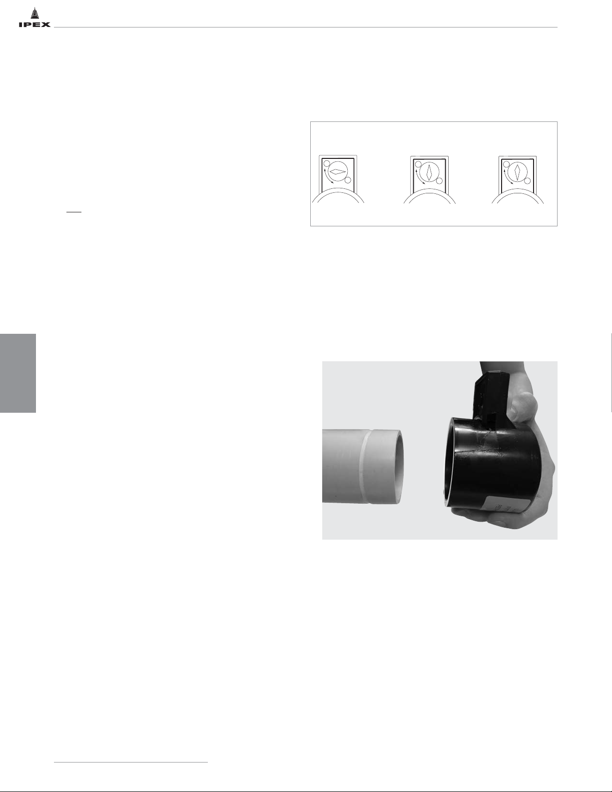
INSTALLATION
62
IPEX Acid Waste Piping Systems
LABLINE AND PLENUMLINE JOINTS
To ensure professional installation, make sure all installers have
undergone training by IPEX in the correct handling, joining and
installation methods of IPEX thermoplastic products.
POINTS TO REMEMBER
a. YELLOW & BLUE ELASTOLIVES DO NOT REQUIRE PRE-HEATING.
If heated, maximum temperature should not exceed
175°F. (79°C)
b. YELLOW LABLINE AND BLUE PLENUMLINE ELASTOLIVES ARE
NOT
INTERCHANGEABLE
c. The pipe end should be clean and there should be no
deep longitudinal grooves in it.
d. It is desirable to use a chain vise to hold 3" and 4" pipe
firmly during cutting and grooving operations. When
grooving 1-1/2" and 2" pipe, a strap wrench should be
used to hold the pipe to prevent its rotation.
e. After grooving, the pipe should be kept clean so that
foreign material is not introduced into the groove.
f. Ensure the grooving tool has a sharp blade to make a
clean-shouldered groove.
g. The cutting blade should always be fully retracted
whenever the tool is put on or taken off the pipe. If any
resistance is felt when putting the tool onto the pipe or
taking it off, the blade position should be checked.
h. Each nut must be fully tightened as the installation
progresses. Do not assemble the system loosely and
tighten nuts last, as layout length errors will go
undiscovered until such time as the nuts are finally
tightened. Avoid misalignment.
i. When tightening fittings, the dry fitting surfaces tend to
bind against each other preventing the nuts from being
fully tightened. To overcome this, either IPEX Acid Waste
Lubricant or IPEX approved petroleum jelly should be used
on fitting threads and elastolives. The lubrication allows
the pipe and elastolive to glide smoothly into position
against the fitting sealing area and enables the nuts to be
tightened to their full thread capacity.
j. Use two spanner wrenches when tightening fittings.
This enables the nuts to be tightened to their full thread
capacity without damaging the fitting.
Procedure
1. Ensure each fitting is supplied with the correct number of
elastolives (sealing rings) and nuts.
2. Verify the grooving tool is sharp. Cut the pipe to the
desired length using a tubing cutter fitted with a wheel
designed for plastic pipe. A handsaw and miter box may
also be used. Ensure pipe ends are square and trimmed
free of burrs.
3. Examine the grooving tool to ensure that the cutting blade
is fully retracted. Insert the pipe into the grooving tool.
4. Set the grooving blade at the half-depth position and
rotate the tool in a counter-clockwise direction. After one
complete turn, set the blade at the full-depth position and
again rotate the tool one full turn counter-clockwise.
Fully retract the blade and remove the tool from the pipe.
A shallow groove has now been formed around the pipe.
Any material left as a feather edge in the groove should be
removed. Care should be taken not to damage the square
edge (shoulder) of the groove, particularly at the edge near
the spigot end of the pipe as this is the primary sealing
surface.
Feathered or rounded edges may indicate a worn tool
and possible leakage. Make sure the groove shoulders
are sharp.
OUT
IN
HALF DEPTH
OUT
IN
FULL DEPTH
OUT
IN
FULLY RETRACTED
GROOVING TOOL BLADE POSITIONING
Page 70
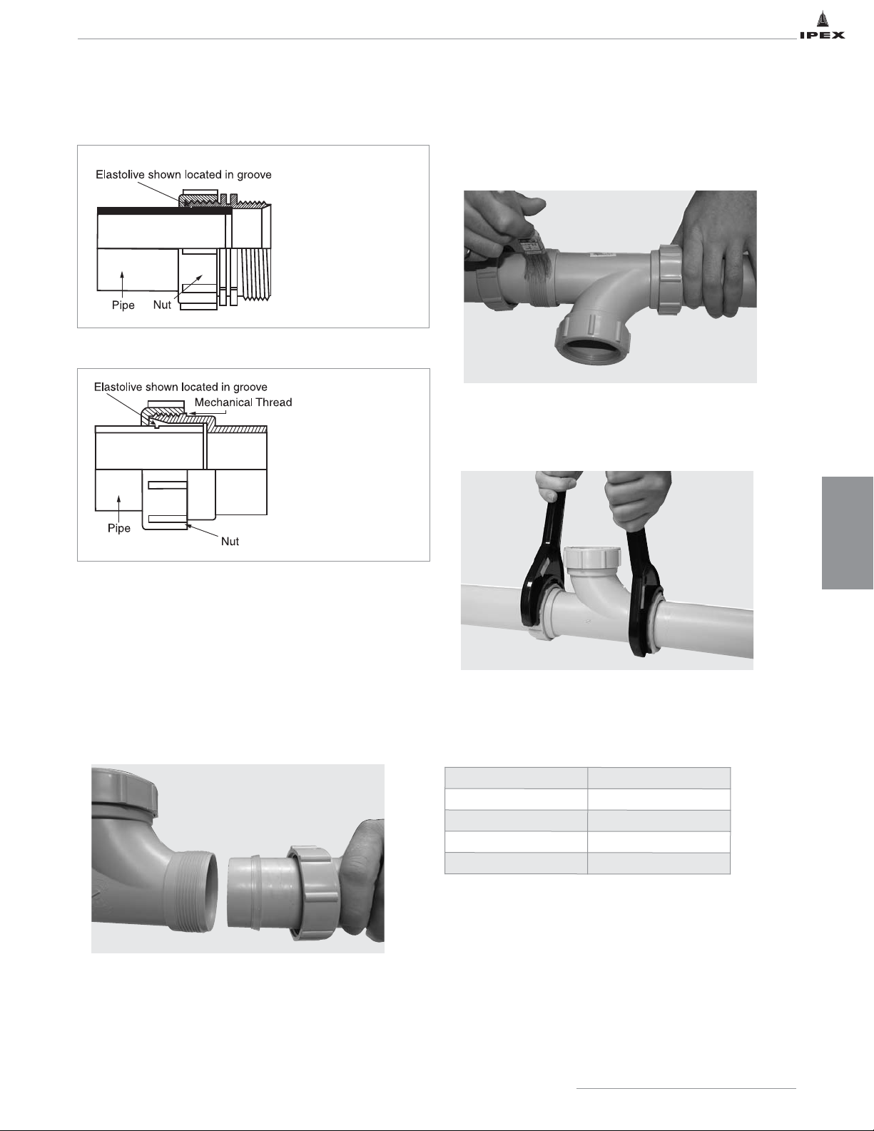
INSTALLATION
63
IPEX Acid Waste Piping Systems
5. Place the nut onto the pipe with the threaded side to the
spigot end of the pipe. Take the elastolive, stretch it and
pull it over the pipe with the thick edge first and the taper
pointing to the spigot end of the pipe. Slide it down the
pipe and onto the groove. Once on the groove “work it” a
bit to make sure that the rib on the underside of the
elastolive engages the full circumference of the groove.
Note: Use IPEX Acid Waste Lubricant on 3" and 4"
elastolives to aid installation when sliding elastolives
on to pipe.
*If you are working on a job that has the old translucent
non-elastic olives, consult your “heat olive” Technical
Bulletin or call IPEX Customer Services for technical
information.
6. Apply IPEX Acid Waste Lubricant or IPEX approved
petroleum jelly to both the thread and the elastolive
then push the pipe squarely into the fitting.
7. Hand-tighten the nut, then tighten, using two spanner
wrenches. The nut must be tightened to its full thread
capacity.
The joint is now ready for testing.
* The figures in the table are estimates based on
laboratory tests
Note: Due to the many variables in the field, these
figures should be used as a general guideline only.
3" and 4" Joint Details
The 3" and 4" joint
design differ from
smaller versions in
that the sealing ridges
are located on the
fitting and the
elastolive extends to
the end of the pipe.
Pipe size (in)
No. of Joints / kg
1-1/2
250
2
250
3
100
4
67
Average Number of Joint per kilogram of
IPEX Acid Waste Lubricant*
1-1/2" and 2" Joint Details
Once engaged in the
groove, the elastolive
virtually becomes part
of the pipe and when
the nut is tightened,
the pipe is locked into
the fitting.
Page 71
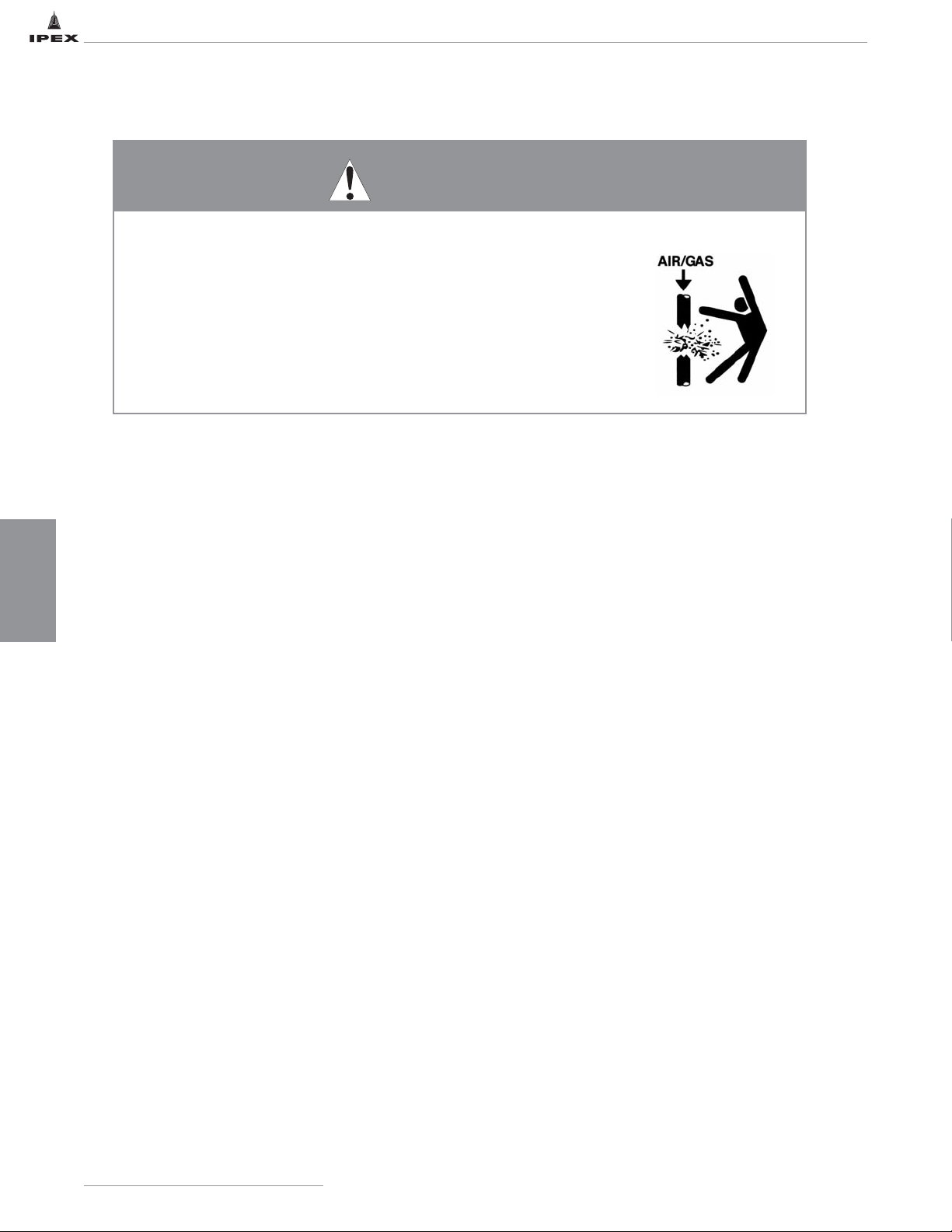
INSTALLATION
64
IPEX Acid Waste Piping Systems
LABLINE AND PLENUMLINE TESTING
The purpose of a site pressure test is to establish that all joints have been correctly made.
Hydro test in accordance with local plumbing code or with authority having jurisdiction or with a maximum of 10 ft of head
pressure. After making the first 20 or 30 joints, it is recommended that a test be applied to prove that the joint-making
technique is satisfactory. If a leak is discovered, follow the appropriate procedure below.
Hydrostatic testing of the joints can be performed immediately after the final joint has been completed. The low pressure
testing procedure detailed below should be strictly followed.
1. Fully inspect the installed piping for evidence of
mechanical abuse and suspect joints.
2. Split the system into convenient test sections, not
exceeding 1,000 feet. The piping should be capped off
with an expandable plug at the end of the pipe section
to be tested.
3. Prior to starting the test in below grade applications,
straight lengths of pipe should be backfilled between
fittings that are tested.
4. Slowly fill the pipe section with water, taking care to
evaluate all trapped air in the process. Use air release
valves in any high spots in the system. Do not pressurize
at this stage.
5. Leave the pipe for at least one hour to allow an
equilibrium temperature to be achieved.
6. Visually check the system for leaks.
7. Pressurize the system to a suggested maximum of 10
feet of head by means of a standard 10' standing water
test using a 10' vertical riser, or a low-pressure hand
pump.
8. Leave the line at 10 of feet head for a period of 2 hours,
during which time the water level should not change
(standing water test), nor should the pressure gauge
reading change (hand pump test).
9. If there is a significant drop in pressure, or extended
times are required to achieve the desired pressure, either
joint leakage has occurred or air is still entrapped in the
line. In this event inspect for joint leaks. If none are
found, check for entrapped air – these air pockets must
be removed prior to continuing the test.
10. If joints are leaking, tighten the nut 1/8 to 1/4 turn and
wipe the fitting to remove excess water. This should
normally cure the problem. If it does not, then the
grooving or setting of the elastolive should be
investigated. Drain the system and undo the suspect
fitting. Test first that the elastolive feels tight on the
pipe by attempting to turn it with reasonable pressure
such as you might use to unscrew the cap of a bottle.
The elastolive should not easily move around the pipe.
If it does, it should be replaced. If the elastolive is tight,
examine it, particularly at the front, for signs of bad
grooving or shavings between the elastolive and the
groove. If the front edge of the groove is damaged, the
joint must be re-made and the piece of pipe replaced.
When examining a leaking 3" or 4" joint, particular
attention should be paid to possible misalignment, as
this is the most likely cause of such a leak. Make sure
any misalignment is corrected before re-testing.
11. Repeat the 10 feet head test after repairing any leaking
joints, following the procedure described above.
• NEVER use compressed air or gas in Enfield, Labline, or Plenumline pipes,
fittings, or accessories.
• NEVER test Enfield, Labline, or Plenumline systems with compressed air
or gas, or air-over-water boosters.
• ONLY use Enfield, Labline, or Plenumline systems for approved chemicals.
Use of compressed air or gas in PP or PVDF pipe and fittings can result in
explosive failures and cause severe injury or death.
WARNING
Page 72
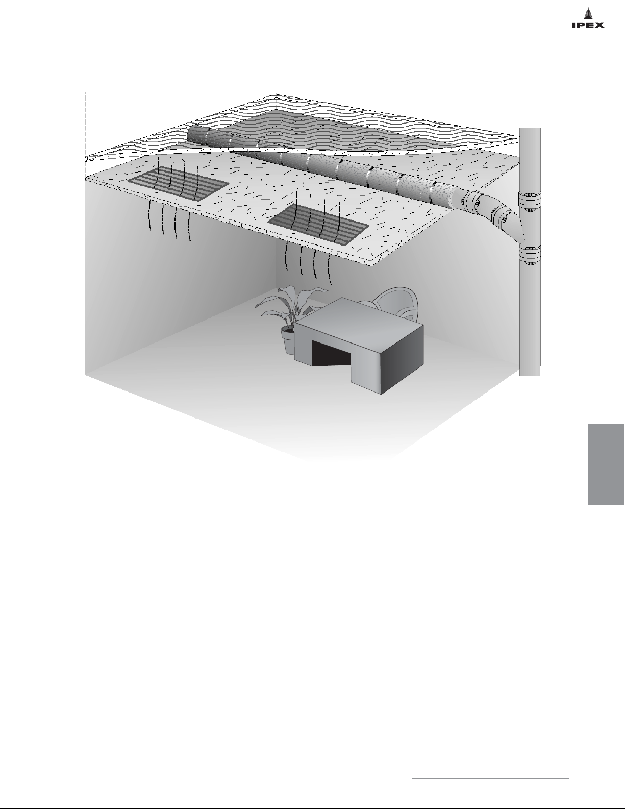
65
IPEX Acid Waste Piping Systems
SECTION FIVE: ADDITIONAL ENGINEERING CONSIDERATIONS
Piping installed in spaces used as return air plenums must have a flame spread rating of 25 or less, smoke development
classification of 50 or less as tested in accordance with ASTM E84 and must meet the requirements of UL723. While glass
piping has been the traditional choice for acid waste piping in plenums, IPEX’s flame retardant polypropylene piping installed
with either a special fiberglass insulation, or with a ceramic fiber plenum wrap, meets these requirements. Third party testing
by ITS labs, was completed on IPEX PP pipe protected with 3M Fire Barrier Plenum wrap. The test results revealed a flame
spread rate of 5 and a smoke development classification of 5. (Plenumline FR-PVDF meets the requirements of ASTM E84 and
UL723 without the use of over-wrap or insulation.)
Features and Benefits:
• Tested in accordance with ASTM E84 requirements for flame spread and smoke development as tested by ITS labs.
• Meets UL723 designation Fire Hazard Classification 25/50
• Meets ASTM E136 for noncombustibility
• Saves cost on material and installation
• Meets the intent of nationally recognized plumbing and mechanical codes.*
• Single source for acid waste piping. Specify and install Enfield, Labline and Plenumline below ground, above ground, in
wall chases, under the bench, and in plenum spaces.
* NOTE: Always check local fire and mechanical codes to ensure compliance.
RETURN AIR PLENUM GUIDELINES
ENGINEERING
CONSIDERATIONS
Page 73
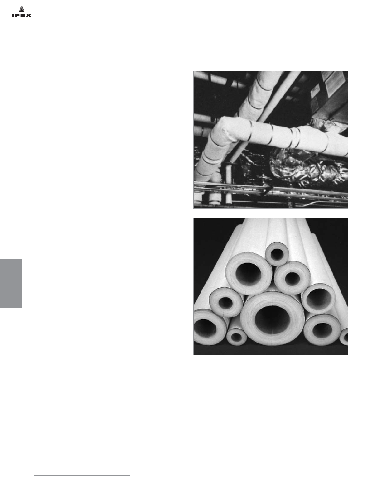
ENGINEERING
CONSIDERATIONS
66
IPEX Acid Waste Piping SystemsIPEX Acid Waste Piping Systems
RETURN AIR PLENUM OPTIONS
Fireproof Fiberglass Insulation
To meet a flame spread index of 25 or less and a smoke
development index of 50 or less when tested in
accordance with ASTM E84 – use Labline or Enfield with
John Mansville Micro-Lok flame-attenuated fiberglass pipe
insulation.
Example Specifications
System Description: Sch 40 FRPP Labline or Enfield acid
waste piping manufactured by IPEX complies with
ASTM E84 and UL723 when covered with one-piece
Micro-Lok AP-T Plus fiberglass insulation, manufactured
by John Mansville. This insulation is a high-density, white
kraft bonded to an aluminized polyester, reinforced with
fiberglass yarn. The kraft paper is chemically treated to
enhance fire safety.
Plenumline PVDF
To meet a flame spread index of 25 or less and a smoke
development index of 50 or less when tested in accordance
with ASTM E84.
The Plenumline flame retardant PVDF piping system does
not require any over-wrap or insulation.
Plenumline PVDF utilizes the same joining method as
Labline polypropylene.
Non-Combustible Ceramic Fiber Pipe Wrap
To meet a flame spread index of 25 or less and a smoke
development index of 50 or less when tested in accordance
with ASTM E84 – use Labline or Enfield with 3M Fire
Barrier ceramic fiber Plenum Wrap. (Complete test results
available upon request.)
Example Specifications
System Description: Sch 40 FRPP Labline or Enfield acid
waste piping manufactured by IPEX complies with
ASTM E84 and UL723 when covered with Fire Barrier
Plenum Wrap, manufactured by 3M Co., consisting of a
patented inorganic blanket encapsulated with a scrimreinforced foil, sealed and secured with aluminum tape
and 1/2" wide stainless steel banding
.
Note: Methods for installing pipe through firewalls should follow the applicable building and plumbing codes and be
approved by the local authority having jurisdiction. A pipe sleeve should be used and the space around the pipe
completely sealed with an approved fire-resistive material. The use of caulk or sealant against the surface of the pipe
is cautioned as some types may not be compatible with the pipe material.
IPEX Acid Waste Piping Systems
Page 74
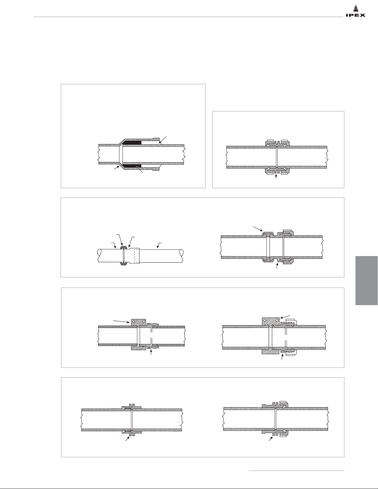
ENGINEERING
CONSIDERATIONS
67
IPEX Acid Waste Piping Systems
ADAPTING TO OTHER DRAINLINE MATERIALS
PVC POLYETHYLENE
OR POLYPROPYLENE
DRAINLINES
IPEX ACID WASTE PIPE
LABLINE OR PLENUMLINE COUPLING
(W16 / W16P SERIES)
The methods depicted below are recommended only as a means of adapting to other drainline materials. Enfield and Labline
components are dimensionally matched to assure installation success. Do not install a system of mixed brands.
Use an Enfield glass adapter and a compression
coupling available from glass drainline vendors.
Use a Labline glass adapter and compression
coupling available from glass drainline vendors.
Use a Labline Duriron adapter and a Duriron coupling
available from silicon iron pipe manufacturer.
1. Roughen or score pipe end with suitable tool or
coarse file to provide a “key”.
2. Insert Enfield pipe until it bottoms at the stop.
3. Pack hub half full with asbestos rope, or acid
resistant oakum.
4. Caulk with hot lead, lead wool or caulking cement.
Use an Enfield Female adapter and Teflon tape.
Use a Labline Female adapter and Teflon tape.
Groove both sections and use Labline coupling.
Glass
Silicon
Iron
Plastic Pipe
Metal
Pipe-
Threaded
Metal Pipe-Caulked
Note: Ensure PP pipe does not melt
Use an Enfield Cast Iron adapter and a Cast Iron
coupling available from iron pipe manufacturer.
POURED LEAD OR CAULKING CEMENT
IPEX ACID WASTE PIPE
METAL PIPE BELL
PACKING
COMPRESSION COUPLING
-Supplied by Glass Vendor
BEADED GLASS PIPE
ENFIELD GLASS
ADAPTER #L45 SERIES
IPEX ACID WASTE PIPE
(L45 SERIES)
CAST IRON MJ COUPLING
SILICON IRON
DRAINLINE
IPEX ACID WASTE PIPE
COMPRESSION COUPLING
BEADED GLASS DRAINLINE
LABLINE ADAPTER TO GLASS
IPEX ACID WASTE PIPE
(W45 SERIES)
CAST IRON MJ COUPLING
SILICON IRON DRAINLINE
IPEX ACID WASTE PIPE
ENFIELD CAST IRON ADAPTER
(L46 SERIES)
METAL DRAINLINE IPEX ACID WASTE PIPE
ENFIELD FEMALE ADAPTER (L15 SERIES)
LABLINE DURIRON ADAPTER
(W46 SERIES)
METAL DRAINLINE
LABLINE OR PLENUMLINE FEMALE ADAPTER
IPEX ACID WASTE PIPE
(W15 / W15P SERIES)
Page 75
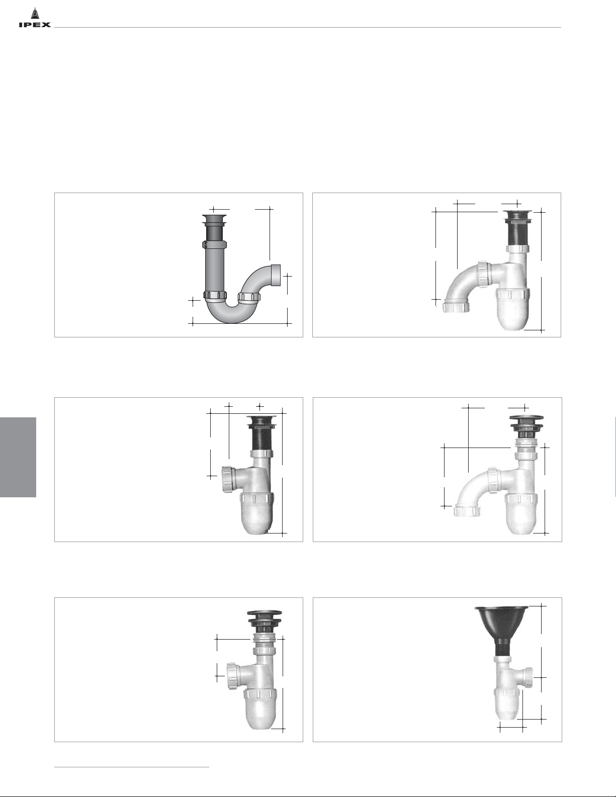
ENGINEERING
CONSIDERATIONS
68
IPEX Acid Waste Piping SystemsIPEX Acid Waste Piping Systems
TYPICAL UNDERBENCH CONFIGURATIONS
2 7/8"
5 1/4"
8 1/2"
W401 6" round cup sink to W501 or W511
Universal trap
1-W401 6" round cup sink
1-W501 or W511 Universal Trap
Note: When connecting traps to
other sink brands use W131
adapter as in illustrations 3 & 5
5 1/2"
9"
11 7/8"
2 7/8"
6 3/8"
11 7/8"
5 1/2"
5 3/4"
8 1/2"
W301 or W311 sink outlet to W501 or W511
Universal trap
Other brand threaded sink outlet to
W501 or W511 Universal trap
W301 or W311 sink outlet to W5015
Universal trap
Other brand threaded sink outlet to
W5015 or W5115 Universal trap
1-W301 or W311 sink outlet
1-W501 or W511 Universal Trap
1-Threaded sink outlet
(other brand)
1-W131 Adapter (use W121
adapter if tail piece is 1
1
/4")
1-W501 or W511 Universal Trap
1-W301 or W311 sink outlet
1-W5015 or W5115
Universal Trap S-Type
1-Threaded sink outlet
(other brand)
1-W131 Adapter (use W121
adapter if tailpiece is 11/4")
1-W5015 or W5115 Universal
Trap S-Type
Tailpiece adapter with P Trap
1-W301 or W311 sink outlet
1-W551 or W5512 swivel sink
strainer adapter
1-W1021 / W1021P 11/2" P Trap
1
2
4
3
5
6
The following configurations are meant to be a guide for installers on the proper assembly of IPEX acid waste systems. They
are acceptable in most applications and allow the product to function in its intended manner. However, one should check with
local authorities having jurisdiction to ensure that the configuration is assembled according to code.
If joints should need pipe thread sealant, IPEX recommends the use of Teflon
®
pipe tape.
IPEX Acid Waste Piping Systems
5 7/8"
2 9/16"
5 3/8"
3 1/4"
8 1/2"
Page 76
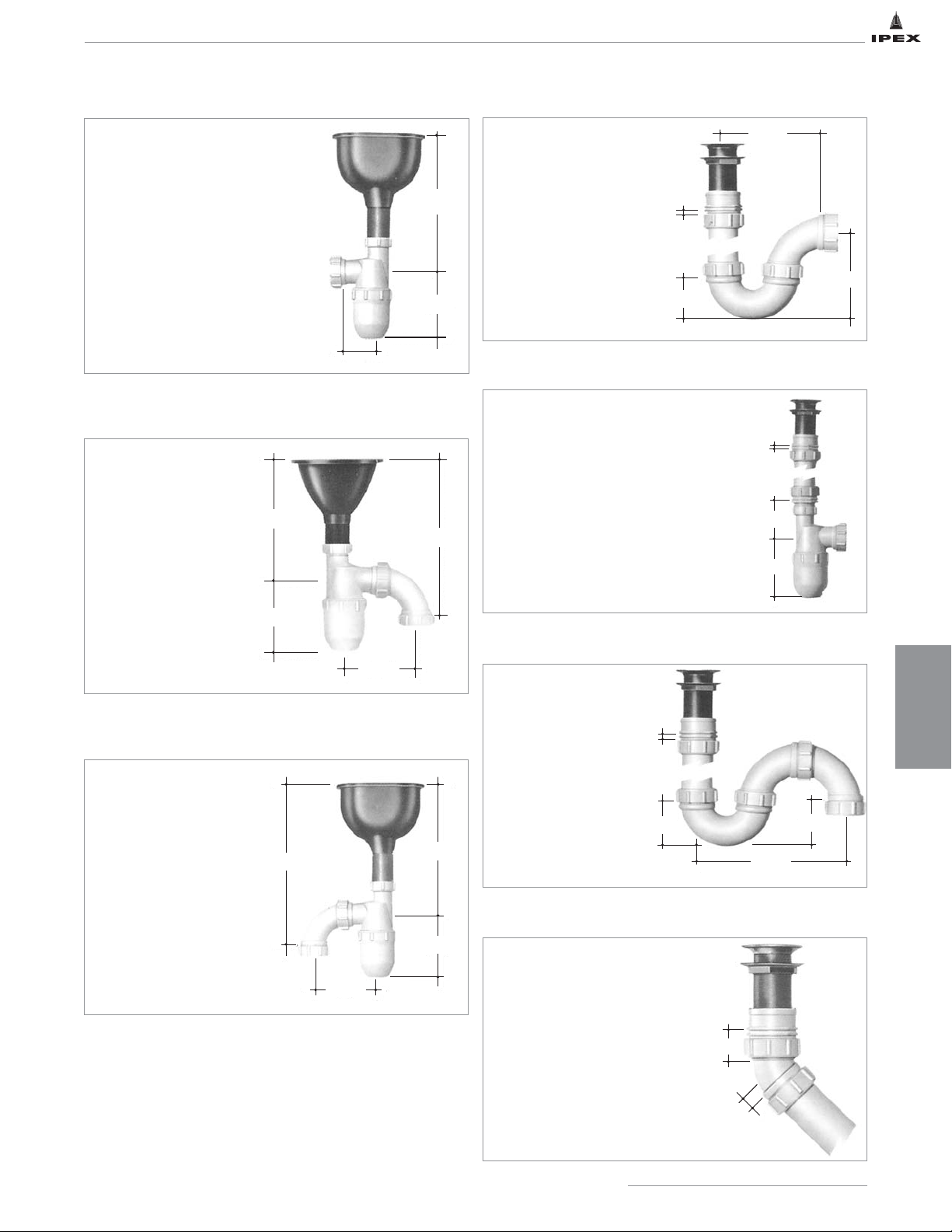
ENGINEERING
CONSIDERATIONS
69
IPEX Acid Waste Piping Systems
5 7/8"
5 3/8"
2 9/16"
1/8"
2"
5/8"
1/8"
2 1/2"
9 1/4"
3 1/8"
W401 6" round cup sink to W5015 or W5115 Universal trap
W497 6" x 3" oval cup sink to W5015 or W5115 Universal trap
W1021 P trap to threaded sink outlet
Long connection of Universal trap to threaded sink outlet
Compact assembly for turning drainline back to wall
1-W401 6" Round cup sink
1-W5015 or W5115
Universal Trap S-Type
1-W497 6" x 3" Oval cup sink
1-W5015 or W5115 Universal
Trap S-Type
1-Threaded sink outlet
1-W151 Female Adapter
1 pc. W001 pipe to length
1-W1021 1
1
/2" P Trap
1-Threaded sink outlet
1-W151 Female Adapter
1 pc. W001 pipe cut to length
1-W141T Male Adapter
1-W501 or W511 Universal Trap
Note: Same assembly also used
for long connections to sinks.
1-Threaded sink outlet
1-W151 Female Adapter
1 pc. W001 pipe to length
1-W1031 1
1
/2" S Trap
1-Threaded sink outlet
1-W151 Female Adapter
1-W211 Loose Nut 1/8 Bend
W497 6" x 3" oval cup sink to W501 or W511 Universal trap
1-W497 6" x 3" Oval cup sink
1-W501 or W511 Universal Trap
10
7
8
9
11
12
13
Connecting W1031 S trap to threaded sink outlet
10 1/2"
5 1/4"
2 7/8"
8 1/2"
11 1/8"
1/8"
3"
5 1/4"
5 1/4"
5 1/2"
13 1/8"
5 1/2"
10 1/2"
5 1/4"
Page 77

70
IPEX Acid Waste Piping SystemsIPEX Acid Waste Piping Systems
NOTES
IPEX Acid Waste Piping Systems
Page 78
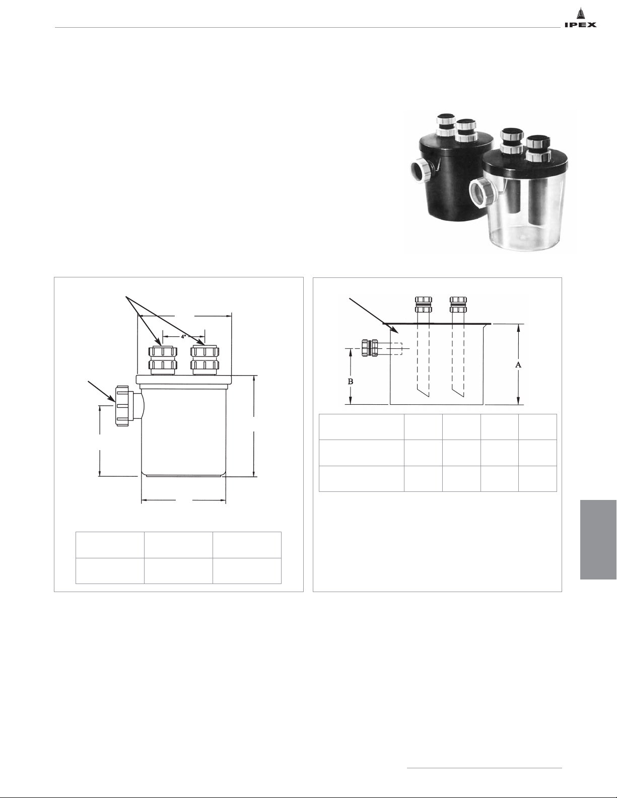
71
IPEX Acid Waste Piping Systems
SECTION SIX: DILUTION AND NEUTRALIZATION
Our complete range of tanks, dilution traps, solids interceptors and accessories are designed to neutralize chemicals
found in laboratory, industrial and institutional wastes.
Dilution Traps
It is often necessary to dilute waste from individual sinks or small groups of sinks
before discharging into the system. Our one-, two-and five-gallon dilution traps allow
for convenient point-of-use dilution of this sink waste.
One-gallon capacity dilution traps have two 1-1/2" loose nut inlets and one 2" outlet.
Various inlet configurations are possible and some are illustrated below. Dilution traps
may serve several sinks or be used as a trap under a particular sink where more than
usual dilution is desirable. Dilution traps may also be used as means of dilution.
If there is no requirement for the unit to incorcorate a trap mechanism, then the dip
tubes can be removed; the unit now acts as a recovery trap only.
Options:
• One or Two Inlets
• 2-or 5-gallon capacity
• Connections available in 1-1/2" or 2" Mechanical Joint
Specify number of inlets and connection sizes when
ordering
Dual 11/2" Inlets
2" Outlet
Trap available in
clear or black
Black Base
One-Gallon Dilution Trap
Dilution Trap / Basin Installation Procedure
• The dilution traps / basins should be situated close to or under the sinks.
• There are 2 x 1-1/2" mechanical joint inlet connections mounted on top of the trap / basin. This allows for up to 2 sinks
to be connected to one dilution trap / basin. One inlet can be blanked off using cap (catalogue number: W461P) if only
one sink is connected.
• The 2" mechanical joint located on the side of the trap / basin is the outlet.
• The trap / basin must be suitably supported from the base, this is required to prevent any undue stress being exerted on
the fittings. Support can also be achieved by situating the trap / basin on the ground.
• The dilution trap / basin must NOT be filled with limestone chips. Limestone chips are only to be used in Neutralization Tanks.
Two and Five-Gallon HDPE Dilution Basin
Clear Black
Part No. W611 W601
Part Number
Size
(gallons)
Diameter
(inches)A (inches)B (inches)
DB02 (rectangular) 2 8 8 8
DB05 (circular) 5 11 13 10
DILUTION AND
NEUTRALIZATION
6 5/8"
9"
8"
9 5/8"
Page 79
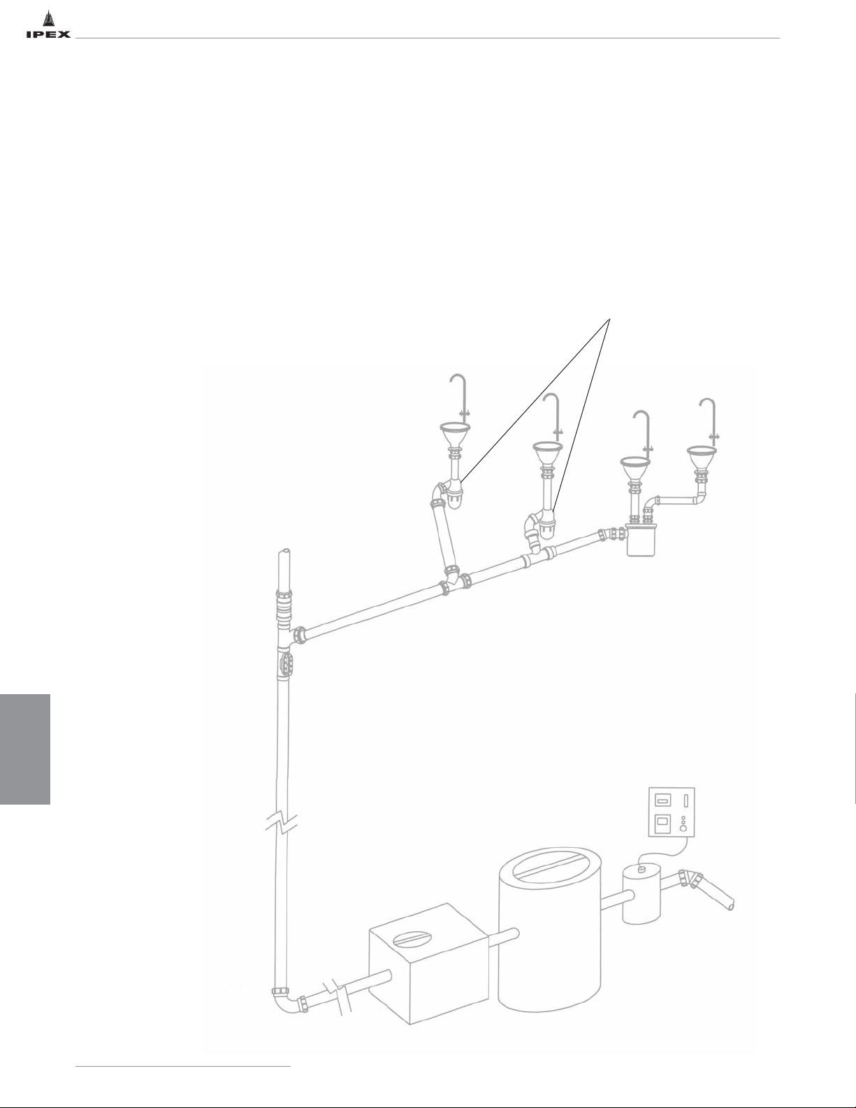
DILUTION AND
NEUTRALIZATION
72
IPEX Acid Waste Piping Systems
Solids Interceptor
Neutralization Tank
pH Monitoring
Tank and Probe
NEUTRALIZATION
Neutralization of waste is necessary to protect the environment as well as attached piping systems. Ideally suited for this
application, polypropylene and polyethylene tanks are a lightweight, durable and cost effective means of neutralizing this
waste and offer advantages not found in tanks made from steel or molded stone. Polyethylene and polypropylene tanks
are easier to handle, corrosion-free and easy to maintain.
IPEX offers a wide variety of tanks (2 to 2000 U.S. gallons) to neutralize harmful chemical waste. IPEX also offers a
variety of equipment to keep tanks free of solids and insure proper flow of liquids through the system. To complete the
neutralization system, equipment can be supplied that will monitor the waste exiting the tanks to ensure equipment is
performing as intended, and alert personnel if there are system problems, such as improper neutralization or flow problems.
Neutratank options:
• Polypropylene or polyethylene construction
• Cylindrical or rectangular shapes
• Variety of sizes (2 - 2000 gallons)
• Bolted covers
• Standard, light traffic or medium traffic covers
• 8", 18", 22" threaded access ports
• Custom tank extensions
• Plain, male or female threaded
or flanged connections
• Fiberglass wrapped tanks –
for increased rigidity, aiding in
direct burial applications
• Solids interceptors
• High/low liquid level alarms
• Inlet flow distributor
• Neutralizing limestone chips
(available in 50 lb. bags)
• pH monitoring system
Universal Traps
Dilution Trap
pH Monitor
IPEX Acid Waste Piping Systems
Page 80
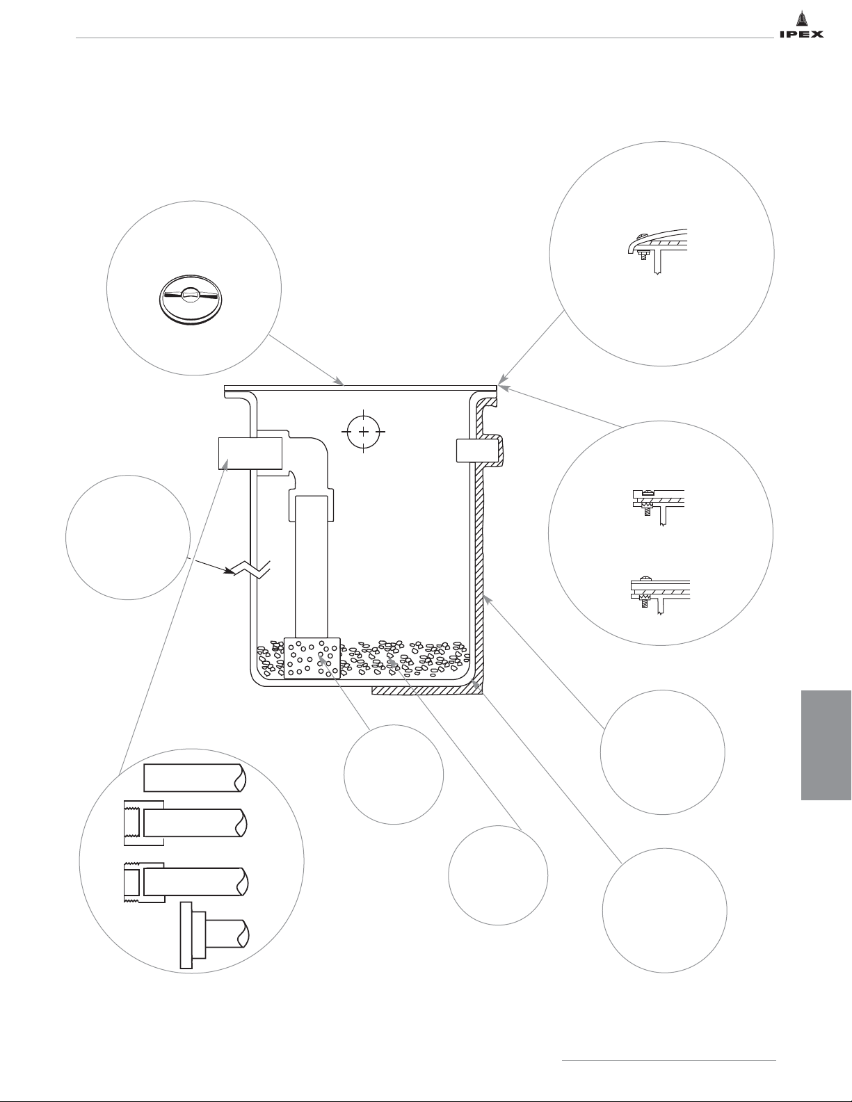
DILUTION AND
NEUTRALIZATION
73
IPEX Acid Waste Piping Systems
CYLINDRICAL TANKS – OPTIONS
TANK COVER OPTIONS
• Bolted Cover
NOTE: Threaded access ports can
be attached to bolted covers.
• Fiberglass
Overwrap
15 gal.-2000 gal.
• Flow Inlet
Distributor
• High Density
Polyethylene
• Polypropylene
• Limestone
Chips
(50 lb. bags)
OPTIONAL COVERS
OPTIONAL TANK REINFORCEMENT
TANK MATERIALS
• Standard Cover
• Typical Pedestrian Traffic Cover
• Custom Tank
Extensions
Contact IPEX
Customer Service for
details
ACCESS PORT OPTION
• Threaded Access Port
Plain End
F. P.T.
M.P.T.
Flanged
CONNECTIONS
INLET/OUTLET/VENT
For details, see ‘Options and Accessories’ page in this section.
Page 81
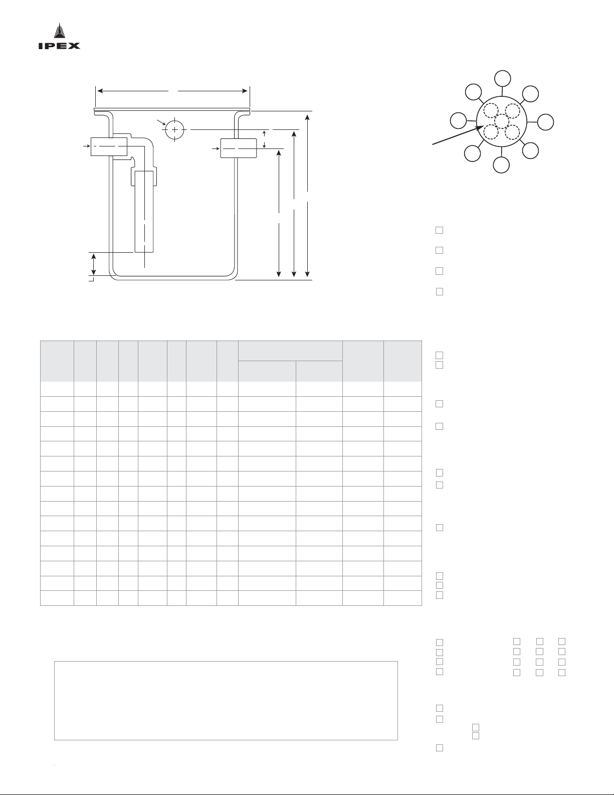
STANDARD CYLINDRICAL TANKS
COMPLETE AND FAX TO YOUR LOCAL IPEX CUSTOMER SERVICE CENTER
(SEE BACK COVER FOR CONTACT INFORMATION)
E
A
F
C
B
D
Inlet
Optional Vent
Outlet
Mark desired location of connections by inserting an “I” for inlet, “O” for outlet and
“V” for vent in the diagram.
Also indicate an “X” at the approximate location of threaded cover (if applicable).
Company Name _________________________________________________
Job Name ______________________________________________________
Date __________________________________________________________
* Available only in HDPE ** Available only in PP
Polypropylene
w/no re-inforcement
Polyethylene
w/no re-inforcement
Polypropylene
w/FRP Wrap (15 gal. & >)
Polyethylene
w/FRP Wrap (15 gal. & >)
Non-load Bearing
Standard Bolted Domed
HD Bolted Flat
Load Bearing
1/8" Smooth Finish Carbon Steel
Pedestrian Traffic Cover
1/4" Diamond Finish Carbon
Steel Pedestrian Traffic Cover
TANK COVERS
MATERIAL
ACCESS PORTS
8" Threaded Access Port
16" Threaded Access Port
22" Threaded Access Port
TANK EXTENSION
Extension Height _____"
(measured from top of standard tank)
PIPE CONNECTIONS
Plain End
Female Thd
Male Thd
Flanged
Inlet/Outlet/Vent
ACCESSORIES
Inlet Flow Distributor
High/Low Level Alarm
Top Mount
Side Mount
Limestone Chips,
qty of bags __________
TANK SPECIFICATIONS
Note: For vehicular traffic applications, IPEX recommends that tanks are installed
below grade with access to the tank vault via DOT approved manhole covers.
Note: Custom sized tanks available upon request. Please contact IPEX for details.
EXTENSION OPTIONS
Non-Adjustable Extension
TM
Variable Extension
TM
Gal.
Dia.
(in)A (in)B (in)C (in)D (in)E (in)F (in)
Extension Height (in)
Specify
Inlet/Outlet
size (in)
Specify
Vent size
(in)
Non-adjustable
Extension
Variable
Extension
*5 11 14 2 10.5 2 15.5 12 6 to 9 6 to 36
**7 11 21 2 16 2 12 18 6 to 9 6 to 36
15 18 15 2 10 2 21.5 12 6 to 14 6 to 36
30 18 29 2 22 3 23 24 6 to 24 6 to 36
55 22 36 2 27 3 24.25 29 6 to 31 6 to 36
100 28 42 2 36 4 32 38 6 to 35 6 to 36
150 31 48 2 38 6 36.5 40 6 to 43 6 to 36
200 36 48 2 38 6 40.5 40 6 to 43 6 to 36
275 42 48 2 38 6 47 40 6 to 42 6 to 36
360 48 48 2 38 6 51 40 6 to 42 6 to 36
500 52 60 2 52 6 56 54 6 to 54 6 to 36
*700 55 70 2 60 6 60 62 6 to 62 6 to 36
*1000 66 72 2 62 6 72 64 6 to 64 6 to 36
*1250 69 84 2 72 8 76 74 6 to 78 6 to 36
*2000 84 84 2 72 8 91 74 6 to 78 6 to 36
Threaded cover location
if applicable. Cover is
centered on 100 gallon
and smaller tanks
Page 82
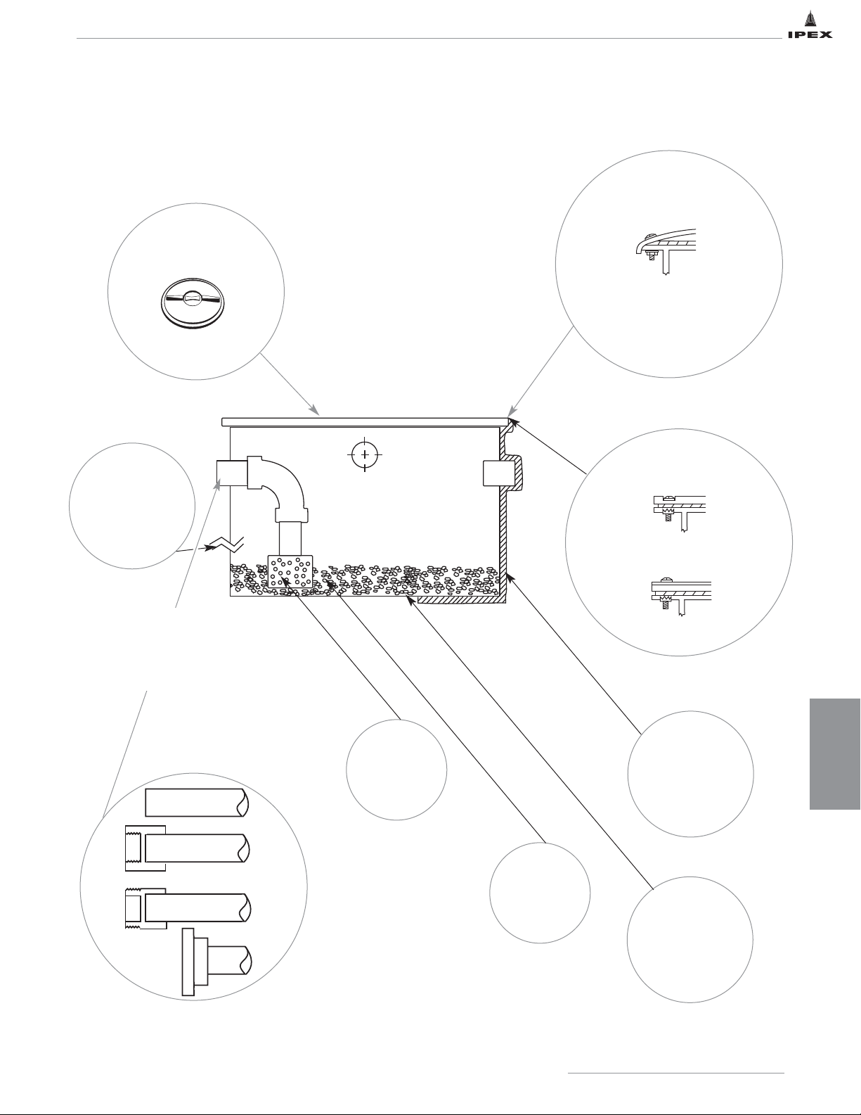
DILUTION AND
NEUTRALIZATION
75
IPEX Acid Waste Piping Systems
RECTANGULAR TANKS – OPTIONS
• Bolted Cover
NOTE: Threaded access ports can
be attached to bolted covers.
• Custom Tank
Extensions
Contact IPEX
Customer Service for
details
• Fiberglass
Overwrap
15 gal.-2000 gal.
• Flow Inlet
Distributor
• High Density
Polyethylene
• Polypropylene
• Limestone
Chips
(50 lb. bags)
OPTIONAL COVERS
OPTIONAL TANK
REINFORCEMENT
TANK MATERIALS
CONNECTIONS
INLET/OUTLET/VENT
Plain End
F. P.T.
M.P.T.
Flanged
• Standard Cover
• Typical Pedestrian Traffic Cover
TANK COVER OPTIONS
For details, see ‘Options and Accessories’ page in this section.
Threaded cover location,
if applicable. Cover is
centered on 100 gallon
and smaller tanks
ACCESS PORT OPTION
• Threaded Access Port
Page 83
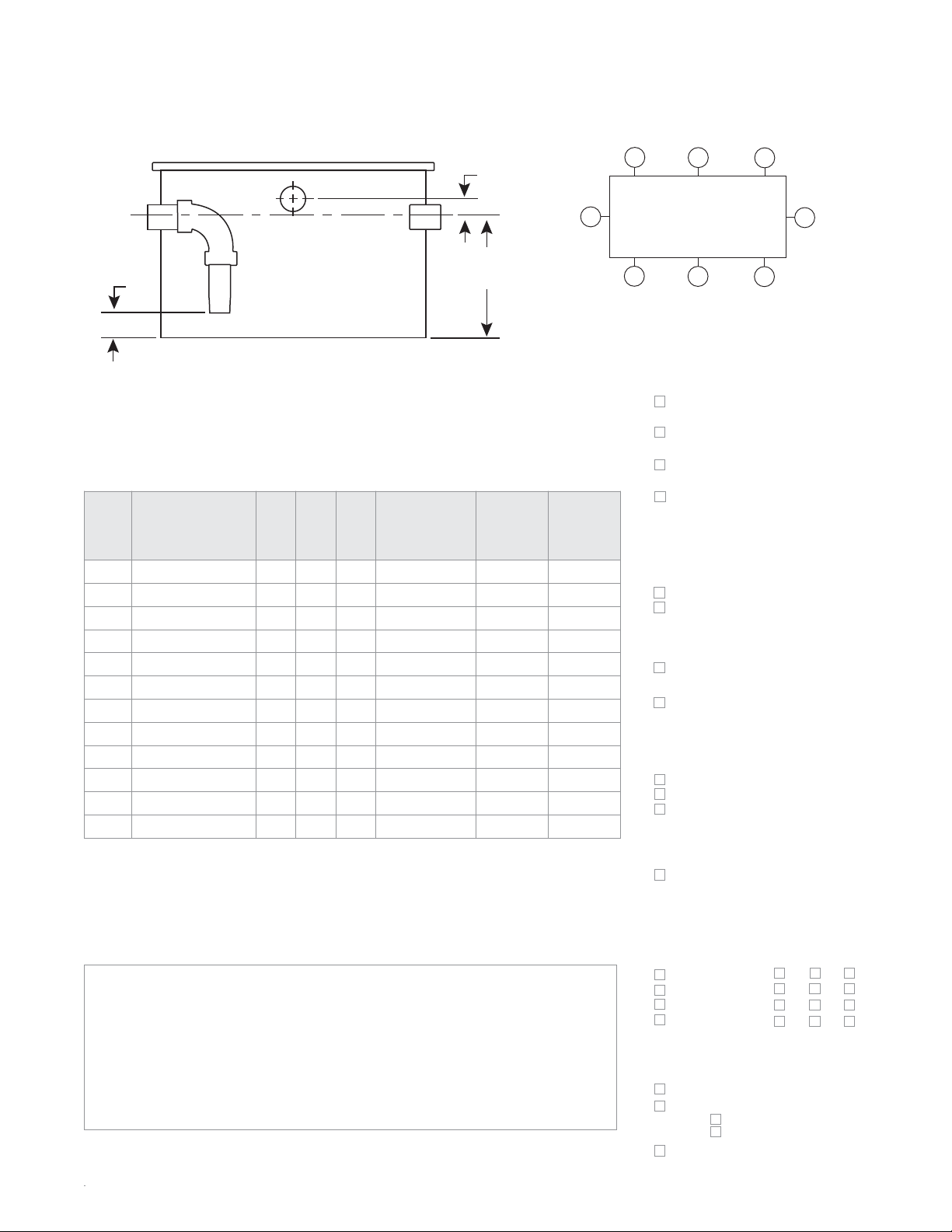
RECTANGULAR TANKS
COMPLETE AND FAX TO YOUR LOCAL IPEX CUSTOMER SERVICE CENTER
(SEE BACK COVER FOR CONTACT INFORMATION)
Mark desired location of connections by inserting an “I” for
inlet, “O” for outlet and “V” for vent in the diagram.
Also indicate an “X” at the approximate location of threaded
cover (if applicable).
Inlet
Outlet
Company Name
_________________________________________________
Job Name ______________________________________________________
Date __________________________________________________________
Note: For vehicular traffic applications, IPEX strongly recommends that tanks are
installed below grade with access to the tank vault via DOT approved manhole covers.
Note: Customized tanks available upon request. Please contact IPEX for details.
TANK SPECIFICATIONS
Gal.
L x W x H
(in)
A
(in)B (in)C (in)
Extension
Height (in)
Non-Adjustable
Specify
Inlet/Outlet
size (in)
Specify
Vent size
(in)
*2 8 x 8 x 8 5 1.5 2 n/a 1-1/2
*5 10 x 16 x 8 5 1.5 2 4
15 12 x 24 x 12 7 2 4 6 to 8
30 12 x 24 x 24 18 2 4 6 to 20
55 24 x 30 x 18 12 2 4 6 to 12
115 30 x 30 x 30 24 2 4 6 to 24
*150 24 x 48 x 30 24 2 4 6 to 24
*215 36 x 36 x 42 36 2 4 6 to 36
*265 36 x 72 x 24 18 2 4 6 to 20
*400 36 x 72 x 36 30 2 4 6 to 30
*540 36 x 72 x 48 42 2 4 6 to 42
*670 36 x 72 x 60 54 2 4 6 to 54
* Available only in HDPE
Non-load Bearing
Standard Bolted Domed
HD Bolted Flat
Load Bearing
1/8" Smooth Finish Carbon Steel
Pedestrian Traffic Cover
1/4" Diamond Finish Carbon
Steel Pedestrian Traffic Cover
TANK COVERS
MATERIAL
ACCESS PORTS
8" Threaded Access Port
16" Threaded Access Port
22" Threaded Access Port
TANK EXTENSION
Extension Height _____"
(measured from top of standard tank)
PIPE CONNECTIONS
Plain End
Female Thd
Male Thd
Flanged
Inlet/Outlet/Vent
ACCESSORIES
Inlet Flow Distributor
High/Low Level Alarm
Top Mount
Side Mount
Limestone Chips,
qty of bags __________
Polypropylene
w/no re-inforcement
Polyethylene
w/no re-inforcement
Polypropylene
w/FRP Wrap (15 gal. & >)
Polyethylene
w/FRP Wrap (15 gal. & >)
B
C
A
Page 84
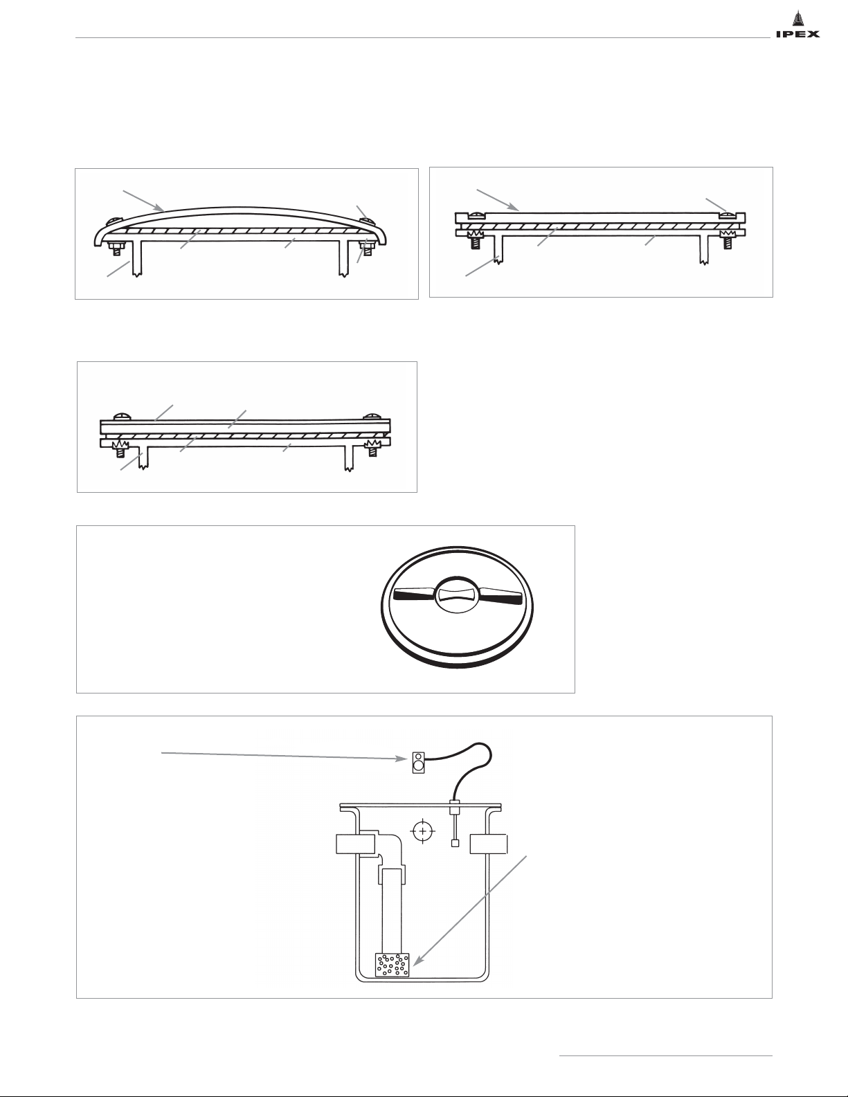
77
IPEX Acid Waste Piping Systems
OPTIONS AND ACCESSORIES
Standard Domed HDPE Cover
Slightly domed - NO Traffic - Non Load Bearing
HD Bolted Flat Cover
NO traffic - Non load bearing for Flush Floor Installations
Steel Pedestrian Traffic Cover - Walking Only
Typical configuration for pedestrian traffic cover
Level Alarm
Poor flow through a tank can often
indicate a clogging problem in the piping
or in the tank itself. Our Hi/Low level
alarms sense when the liquid level in the
tank is above or below the desired level
and then sound an alarm to indicate
there is a problem. These alarms can be
installed in most any tank and can be
fitted with either an audio or
visual alarm indicator.
Inlet Flow Distributor
The Inlet Flow Distributor provides the
following functions:
• even distribution of waste from the
inlet
• greater efficiency of the limestone bed
• prevents limestone chip backup into
inlet
Dome Cover with Overhang
Round Head Slotted
Bolts with Washers
Hex Nuts with Washers
Tank Top FlangeNeoprene Gasket
Tank Wall
Polyethylene/Polypropylene Cover
Round Head Slotted Bolts with
Washers in Recessed Bolt Holes
Tank Top FlangeNeoprene Gasket
Tank Wall
For Flush Floor Installations
Round Head Slotted
Bolts with Washers
(bolts not recessed)
Steel Cover
Over 1/2" PP Cover
Tank Top FlangeNeoprene Gasket
Tank Wall
Threaded Manway
Threaded ports can be incorporated into all non
traffic - non load bearing covers. They are
available in three sizes: 8", 16" and 22"
diameter.
Page 85
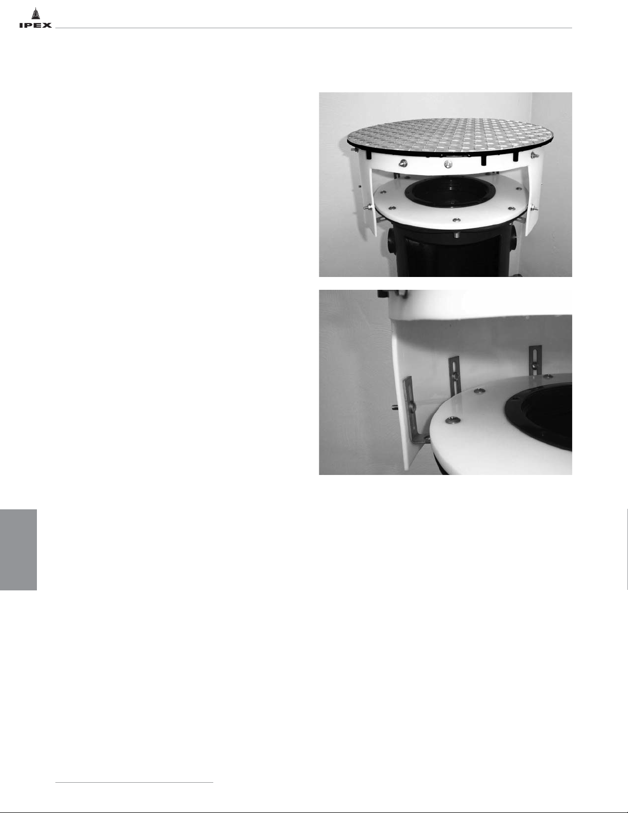
DILUTION AND
NEUTRALIZATION
78
IPEX Acid Waste Piping SystemsIPEX Acid Waste Piping Systems
NEUTRATANK EXTENSIONS
IPEX Acid Waste Piping Systems
Neutratank Adjustable Extension
Designed for easy access to direct bury tanks, the Variable
Extension’s steel cover and poly sidewall body allows for 2"
of vertical adjustment for leveled installation regardless of
grade changes. The 1/4" thick steel floor plate cover and
frame, suitable for installation in finished floors, are rated
for heavy duty pedestrian traffic and are provided with a
16" threaded manway for ease of maintenance and
inspection.
Features & Benefits:
• Allows easy access to direct bury tanks
• 1/4" thick steel floor plate cover and frame suitable for
installation in finished floors
• Cover is rated for heavy duty pedestrian traffic
• Steel cover and poly sidewall have 2" of vertical
adjustment
• Extension heights are 6" to 36"
(contact factory for extensions exceeding 36")
• Neutratank poly cover provided with 16" threaded
manway for ease of maintenance and inspection
• Poly sidewall protects tank lid during backfill and keeps
tank lid free of debris for maintenance and inspection
Page 86
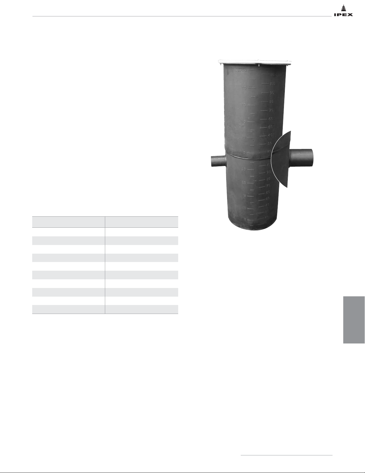
DILUTION AND
NEUTRALIZATION
79
IPEX Acid Waste Piping Systems
Neutratank Non-adjustable Extension
Designed for easy access to tanks with deep bury depths,
the Non-Adjustable Extension is manufactured to your
specific site conditions.
Features & Benefits:
• proprietary method of seaming extensions together
provides exceptionally strong joints
• non-adjustable tank extensions are manufactured to
specific site conditions
• allows easy access to tanks with deep bury depths
• tanks can be FRP wrapped for direct bury applications
• extended tanks are available with standard domed,
HD bolted flat, or steel pedestrian traffic covers
• available in both HDPE and Polypropylene
• standard extension heights are offered and are
determined from the top of standard tank
Tank Size (Gallons) Extension Length (Inches)
5 / 7 6 to 9
15 6 to 14
30 6 to 24
55 6 to 31
100 6 to 35
150 6 to 43
200 6 to 43
275 6 to 42
350 6 to 42
500 6 to 54
Page 87
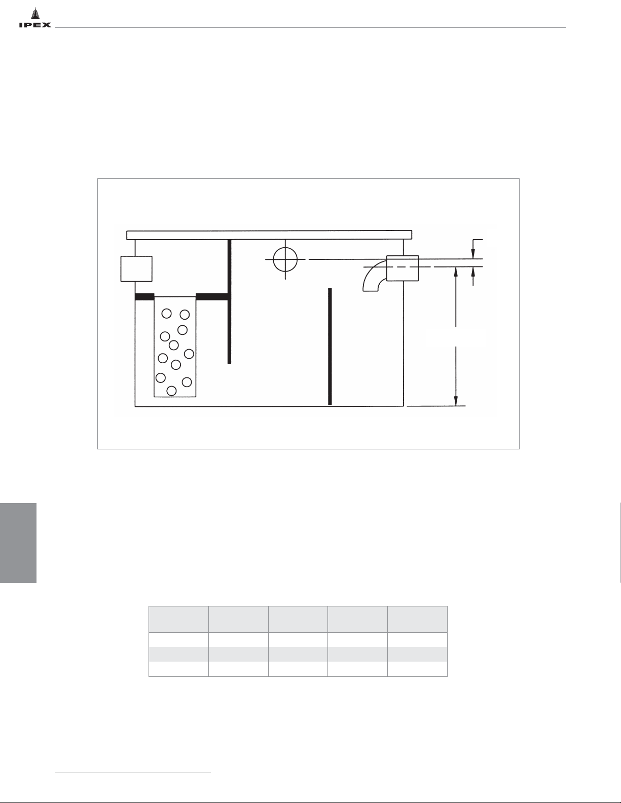
DILUTION AND
NEUTRALIZATION
80
IPEX Acid Waste Piping Systems
SOLIDS INTERCEPTION
Grease, hair, lint and other laboratory debris can enter the waste system and often cause clogging and system back-ups.
Solid waste can build up in the system which can lead to flooding and damage to the piping. If the solids are not removed
from the system at the source, they can lead to permanent stoppages in the piping. The stoppages in the system will lead to
costly and inconvenient cleanings and possible replacement of the piping. IPEX manufactures a line of solids interceptors
which will filter out these solid waste products prior to entering the main piping system. Standard units are manufactured
from high-density polyethylene. Propropylene units are available upon request.
Options:
• Inlet Filter Basket
• Bolted or Welded Cover
• Access Port
• Optional Vent
A
B
Part
Number
Size
(gallons)
Diameter
(inches)
A
(inches)
B
(Inches)
SI14 14 12 x 12 x 24 18 1-1/2
SI44 44 18 x 24 x 24 18 1-1/2
SI75 75 24 x 24 x 30 24 1-1/2
Page 88
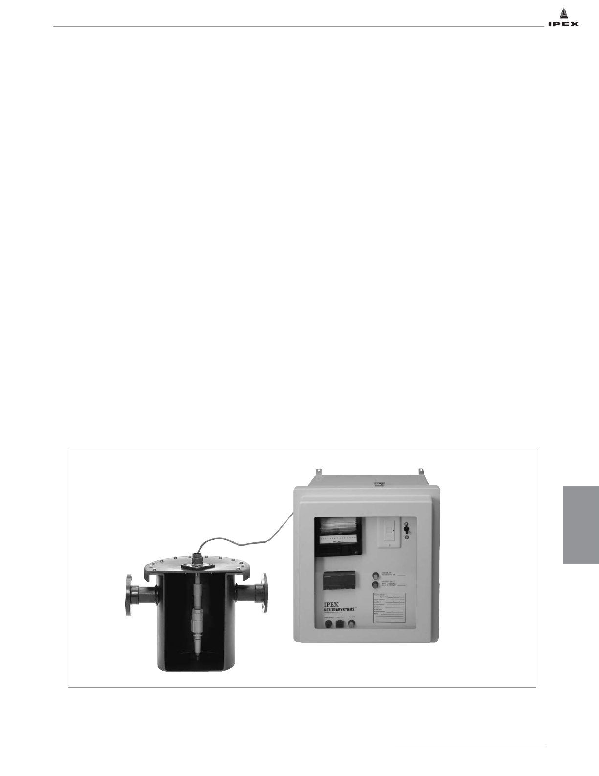
DILUTION AND
NEUTRALIZATION
81
IPEX Acid Waste Piping Systems
NEUTRASYSTEM 2
TM
pH Monitoring, Recording, and Alarm System
Neutrasystem 2 ensures that discharges into the sewer are
maintained within acceptable pH parameters by neutralizing
the acidic waste with limestone chips. The system
continuously samples the downstream flow while keeping an
accurate, permanent record of pH discharge levels. The
monitoring device will warn maintenance personnel, (visually
and audibly), when pH discharges outside acceptable
parameters are sensed. Once alerted, maintenance personnel
can quickly and easily recharge the main IPEX Neutratank
with limestone chips through the access cover incorporated
into the tank’s design.
The system incorporates the following features:
• UL 508 listed, NEMA 4X enclosure with hinged clear front
cover for easy reading and access.
• 110/120 VAC input power supply with GFI power cord
protection and 24V DC operating voltage
__
provides
stabilized operating current for panel instrumentation and
allows the use of low voltage cable for quick, easy
installation in the field.
• Control power circuit breaker, re-set protection (no fuses).
• Continuous soft internal alarm horn, (sonalert type), and
alarm silencing button. The alarm horn is activated when
the probe senses a pH above or below the set parameters,
and will remain on until the alarm silence button is
pressed.
• 31-day strip chart and single pen recorder __maintains a
permanent record of pH levels.
• “Power On” yellow light indicates that incoming
110/120 VAC power and the 24V DC system
are functional.
• “pH Alarm” red light indicates when the measured pH is
outside acceptable parameters. The light will remain
illuminated until the fault is cleared and the “System OK”
green light is re-illuminated.
• “System OK” green light indicates that the system is
on-line and not in a default condition.
• 0-14 pH pH PHCN micro-processor based pH controller
with digital LED display.
• Series 6510 submersible, pH electrode with
chemically resistant CPVC body, viton O-rings and
twist- lock connection providing easy maintenance.
• 5-gallon high density polyethylene, one-piece construction,
rotationally molded sample tank.
Page 89
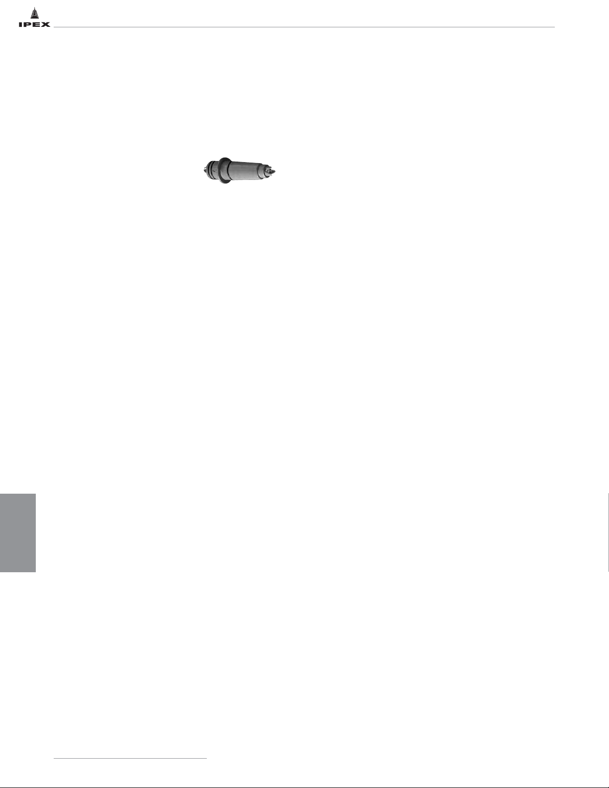
DILUTION AND
NEUTRALIZATION
82
IPEX Acid Waste Piping Systems
NEUTRASYSTEM 2
TM
IPEX NEUTRASYSTEM 2 uses a CPVC submersible electrode (sensor) with automatic temperature compensation. The sensor
has a flat surface junction to minimize fouling. The reference is sealed to minimize dryout and eliminate refilling solution.
The sensor is connected to a preamplifier by a 1/4 turn quick disconnect. The preamplifier has an attached cable for
connection to the pH Controller in the NEUTRASYSTEM 2 panel. The cable has a BNC connector for the sensor signal
and 3 spade terminals for automatic temperature compensation.
pH Electrode
Storage
The pH electrode is shipped in a soaker bottle containing a
solution of pH 4 buffer and potassium chloride. The
electrode should remain in the bottle until it is ready to use.
If the electrode is used infrequently, the cap, bottle and
solution should be saved and the electrode stored in it. Store
the pH electrode in a pH 4 buffer solution if the soaking
solution is discarded. Do not use distilled or deionized water
as this will drastically reduce the electrode lifespan. Remove
the cap and o-ring on the soaker bottle before use.
Maintenance
pH electrodes have a thin glass surface. Care should be
taken so that the glass does not become scratched or broken.
After exposure to a sample, buffer or rinse solution, carryover
can be minimized by blotting – never by wiping – the
electrode with a clean, non-abrasive paper or a clean cloth
towel. Do not use a brush on pH glass. As a rinse solution,
use a part of the next sample or buffer which is to be
measured. This action will also minimize contamination
from carryover.
Replacement
All pH electrodes age with time. Aging is characterized by
shortened span and slower speed of response. Electrodes
should be replaced when their readings cannot be corrected
by the meter's controls and/or when their speed of response
is too slow for the application for which they are being used.
The frequency of electrode replacement is a function of the
application; electrodes operating in hot liquids at very high
or very low pH values will have shorter lives than those
operating at neutral pH and ambient temperature. Coatings
on an electrode's surface prevent new liquids from contacting
an electrode's measuring surface and can mimic the effects
of electrode aging. Before concluding that an electrode needs
replacing, check its surface for coatings.
Calibration
The frequency of calibration is solely the responsibility of the
user. At a new installation, calibration might be checked
every few hours or shift, with the calibration changes noted in
a log. As a pattern of longer stability is found, the time
between calibration checks can be increased to once a day or
once a week. Once a week is the longest recommended
interval between calibrations.
• The pH electrode and pH controller should always be
calibrated as a system.
• Only buffer solutions of 4, 7 and 10 are acceptable.
• Before placing the electrode in a new buffer, use an
absorbent paper towel or clean absorbent cloth to blot –
not wipe – off any liquid that clings to the electrode.
This action will minimize carryover that could
contaminate the buffer.
• Always use fresh buffers. Safely dispose of the buffers
after they have been used for calibration. Do not return
them to their bottles. This action could contaminate the
buffers.
• Stir the electrode in the buffer to make sure that the
fresh buffer quickly reaches the electrode’s measuring
surface.
• Allow time for the reading to stabilize. In general, with
new electrodes, stable readings in the buffer solution are
obtained in 10-15 seconds.
Cleaning
Coating of an electrode’s measuring surface can lead to
incorrect readings, including shortened span and slower
response times. The type of coating determines the type of
cleaning technique. When using chemicals or solvents, care
should be taken and appropriate eye, face, hand and/or
respiratory protection should be used.
Soft Coatings can be removed by vigorous stirring, by use of
a squirt bottle or, very carefully, by gently wiping with a soft,
clean non-abrasive paper or cloth. Do not use any brush or
abrasive cleaner on pH glass.
Hard Coatings should be chemically removed. The chemical
used to remove the coating should be the least harsh
chemical that dissolves the coating in one or two minutes
and does not attack the electrode’s material of construction.
Oily or Organic Coatings are best removed with detergents or
an appropriate solvent that does not attack the electrode’s
material of construction.
NOTE: For detailed Operating, Maintenance and Calibration
Procedures for Neutrasystem 2, please contact IPEX
Page 90
DILUTION AND
NEUTRALIZATION
83
IPEX Acid Waste Piping Systems
NEUTRALIZATION TANK SIZING AND MAINTENANCE
The size of the neutralization tank is a function of the
number of sinks and drains that are discharged into the
system. According to ASPE, tanks are sized to provide a
minimum “dwell time” of 2-1/2 to 3 hours. Based on this
dwell time, ASPE has developed a sizing table which is
summarized and can be used as a guide in selecting the
proper size tank. Tanks should not be sized based on the
number of sinks or drains alone. Certain types of waste may
require particular needs and may not fall within the standard
sink to tank ratio. Other factors that can affect the tank size
are not limited to, but inclusive of: the amount of flow
through the system, the type of chemicals and the size of the
system piping. A qualified engineer should make the final
determination of the tank size.
Maintenance
The limestone chips supplied by IPEX are 1" to 3" in
diameter and have a calcium carbonate content certified to
be in excess of 90%. Water should always be added to the
tank to help facilitate dilution. A maintenance schedule
should be established to observe and maintain proper levels
of limestone in the tank. Limestone replacement should be
performed at regular intervals. Typically, once every one to
three months is sufficient, however, these intervals can be
increased or decreased based upon application needs and
performance. Factors affecting limestone replacement are
waste flow rates, pH levels, chemical composition and
operating temperatures. Solids in the waste stream can plug
the tank and should be avoided.
NOTE: There are many variables that affect neutralization and
dilution of chemicals discharged through a system.
Professional assistance should be employed in analyzing the
effluent and the necessary maintenance service frequency.
Tank Size and Limestone Loading Chart
Number
of Sinks
Tank Size
(gallons)
Limestone Loading for
Neutralization (lbs)
2 5 50
4 15 125
8 30 250
16 55 500
30 100 1000
40 150 1500
60 200 2000
75 275 2500
110 360 3500
150 500 5250
215 700 8000
275 1000 10000
315 1250 12000
500 2000 18000
Page 91
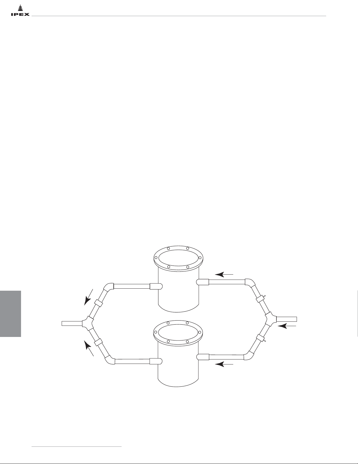
DILUTION AND
NEUTRALIZATION
84
IPEX Acid Waste Piping SystemsIPEX Acid Waste Piping Systems
Neutralization Tank Sizing Example
A manufacturing process has a discharge cycle that activates a discharge pump for 5 minutes every 30 minutes. The pump
capacity is 10 gpm. The acid waste is then directed into the acid waste drainage pipe system. The piping system must
therefore be capable of conveying 100 gallons/hour. What size neutratank would be necessary to neutralize this discharged
acid waste?
Design Requirements:
• Pump capacity 10 gpm
• Pump operates for 5 minutes every 30 minutes
• Flow rate max 100 gallons/hour
Assumptions:
1. Nameplate tank capacity is reduced by 20% due to
position of inlet and outlet.
2. Limestone distribution further reduces available liquid
volume by 65%. This may vary by random mixture or
stone sizes, settling or dissolving of the stones.
3. Dwell time design for a pH1 is between 2.5 and 3 hours
to result in an effluent between a pH of 4 and 7.5.
Solution:
• require tank to have a liquid capacity of 250 gallons
(100 gal/hr x 2.5 hrs)
• Tank total liquid volume capacity is
250 gallon/.35 = 714 gallons
• Nameplate capacity due to inlet and outlet is
714/.80 = 892 gallons
• Recommendation is 1000 gallon tank or 2 – 500
gallon tanks in parallel
Piping Tanks in Parallel
Flow
Valve
Flow
Valve
Flow
Page 92
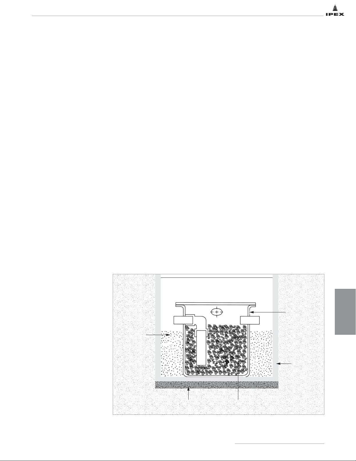
DILUTION AND
NEUTRALIZATION
85
IPEX Acid Waste Piping Systems
NEUTRALIZATION TANK INSTALLATION
Exercise care when handling neutralization tanks. Damage may
occur if the tank is dropped, dragged, or collides with sharp
corners or objects. Improper handling of the tank during
installation can cause structural failure.
Neutratank Installation and Application Advice
1. Tanks must be placed on a flat, solid surface allowing
uniform, full support to the tank bottom. Such surfaces
may be basement floors, concrete pads or compact,
stone-free sand beds.
2. The tank itself must not be used to support manhole
covers, traffic of any kind or heavy equipment.
3. Do not support the tank by inlet, outlet, vent or any
connecting piping.
4. Do not place any weight on tank fittings or connecting
piping.
5. Depending upon effluent content, HDPE tanks may be
used at temperatures up to 140ºF (60ºC). Polypropylene
tanks may be used at temperatures up to 212ºF (100ºC).
6. Where possible, fill the tank with water prior to
introducing the limestone and media.
7. Tank insulation may be considered for outdoor installation
in cold environments.
Buried Tank Installation
Tanks must be fully supported on the base by either an
appropriate concrete pad that allows no overhang or a
compacted stone free sand bed.
Buried tanks must be filled with
water prior to backfilling. Tank
tops are non-load bearing and
should have a trap door or
access cover over them
supported by a foundation or by
the ground. They cannot be
supported by the top of the
tank. The backfill material shall
be free of stones and foreign
matter and shall be capable of
passing a No. 10 screen. The
depth of this backfill should be
6" to 8" thick around the tank
and then normal backfill
material may be used.
Mechanical tamping is not
recommended. Care must be
exercised during the backfilling
procedure to prevent inward
buckling of the tank.
For tanks with extensions, the above procedure should be
followed up to or slightly above water level and from that
point on up to ground level it is recommended that a 4" thick
concrete sleeve be poured around the tank in multiple lifts.
If this is not feasible then the normal backfill procedure may
be used, up to 36" height above water level, bearing in mind
that backfilling will produce inward pressures on the empty
portion of the tank. Care must be exercised during this
operation to prevent inward buckling.
In areas with high water tables, subject to flooding, or poor soil
conditions; IPEX recommends tanks be secured within a
concrete vault, or a 4" thick concrete sleeve poured around
the tank in multiple lifts. If the tank is to be used as a
pump-out holding tank or similar type of operation or the
tank will be left empty or partially full, then IPEX
recommends that tanks be secured within a concrete vault.
IPEX recommends that tanks should never be buried directly
in the ground unless they are wrapped in fiberglass. IPEX can
supply fiberglass wrapped tanks upon request.
These recommendations should always be referenced against the
local authority having jurisdiction.
Testing
Tanks must NOT be subjected to pressure or vacuum
including hydro-testing. Test tank by filling with water
prior to use and inspect for any leaks.
Soil
Neutralization
Tank
Concrete
Vault
Limestone ChipsBedding Material
Sand Fill
between
Tank and Vault
(6" - 8")
Page 93

ACID WASTE
SPECIFICATIONS
86
IPEX Acid Waste Piping SystemsIPEX Acid Waste Piping Systems
SECTION SEVEN: ACID WASTE SPECIFICATIONS
ENFIELD®SPECIFICATIONS
Enfield Long Form
General
Acid waste drain and vent system, as shown on drawings,
shall be NSF listed and CSA certified Schedule 40,
polypropylene as manufactured by IPEX. System to
include pipe supplied in 10 ft. lengths (or 20 ft lengths if
NFRPP is specified), fittings, traps and neutralization
tanks from the same manufacturer. It shall also include
recommended adapters to connect to other piping
materials, where applicable.
Material
Pipe shall be made from NSF listed Type 110 or 210,
flame retardant polypropylene conforming to ASTM D4101,
with a maximum average flame spread of zero seconds and
a maximum extent of burning of 13 mm, in accordance
with ASTM D635. Matched fittings shall be made from
NSF listed flame retardant polypropylene with average
maximum burn time of 80 seconds and maximum extent of
burning of 20 mm in accordance with ASTM D635.
If NFRPP pipe is specified, it shall be made from NSF 14
listed and CSA certified Schedule 40 PP as manufactured
by IPEX.
Pipe shall comply with ASTM F1412 and material used
shall comply with the material requirements of ASTM
D4101.
Fittings
Fittings shall be NSF listed and have an integral heavy
gauge, nickel/chrome electrical resistance wire molded in
place in the fitting body. Copper wire elements, loose wire
or other loose joint components, are prohibited. Fittings
shall be Enfield or approved equal.
Joints
Connections between polypropylene pipe and fittings shall
be made using the Enfield joint. All joints shall have a
fusion cycle controlled by a microprocessor operated,
waterproof, Enfusion control unit equipped with input and
output voltage sensors, ambient temperature sensors to
automatically adjust fusion time and audible alarms to
indicate cycle interruptions and completion of the joining
process. The unit shall be capable of fusing multiple joints
and with a minimum capability of six 2" joints with the
same fusion time as a single joint.
Connections between polypropylene and other piping
materials shall be made using Enfield adapters according
to manufacturer’s (IPEX) recommendations. All
electrofusion machines shall be third party certified by
UL and CSA.
Installation and Testing
Installation and testing shall be in accordance with the
contract drawings, the manufacturer’s recommendations
and the local plumbing codes. Testing with compressed air
is prohibited. The entire system shall be installed free of
stress and in proper alignment. Horizontal supports shall
provide a wide bearing area and be free of burrs or sharp
edges. Support spacings shall be in accordance with the
manufacturer’s recommendations and local plumbing
codes. Vertical piping shall have riser clamps at each floor.
Pipe supports should be installed so that horizontal piping
is in uniform alignment and with a uniform slope of at
least 1/8" per foot, or in accordance with the local
plumbing codes.
Enfield Short Form
Acid waste drainage and vent system shall be NSF listed and CSA certified Schedule 40, flame retardant
polypropylene joined by Enfield resistance wire, as manufactured by IPEX. All fittings shall have integral
nickel/chrome resistance wire with no loose components. Jointing shall be controlled using a UL and CSA certified
microprocessor operated Enfusion Control Unit incorporating self diagnostics and automatic audible alarms to indicate
circuit defaults and joint completion, plus allow multiple jointing of fittings at the same fusion time as a single joint.
Installation and testing shall be in accordance with the contract drawings, the manufacturer’s recommendations and
the local plumbing codes.
Page 94

ACID WASTE
SPECIFICATIONS
87
IPEX Acid Waste Piping Systems
LABLINETMSPECIFICATIONS
Labline Long Form
General
Acid waste drain and vent system, as shown on drawings,
shall be NSF listed, Schedule 40, polypropylene as
manufactured by IPEX to include pipe supplied in 10 ft.
lengths (or 20 ft lengths if NFRPP is specified), and
matched fittings, traps and neutralization tanks from the same
manufacturer. It shall also include recommended adapters to
connect to other piping materials, where applicable.
Material
Pipe shall be made from NSF listed Type 110 or 210, flame
retardant polypropylene conforming to ASTM D4101, with a
maximum
average flame spread of zero seconds and a maximum extent
of burning of 13 mm, in accordance with ASTM D635.
Matched fittings shall be made from NSF listed flame
retardant polypropylene with average maximum burn time of
80 seconds and maximum extent of burning of 20 mm in
accordance with ASTM D635.
If NFRPP pipe is specified, it shall be made from NSF 14
listed and CSA certified Schedule 40 PP as manufactured
by IPEX.
Pipe shall comply with ASTM F1412 and material used shall
comply with the material requirements of ASTM D4101.
Fittings
Fittings shall be NSF listed, be of all plastic construction and
be designed to lock into a machined groove on the mating
piping. All fittings shall have integrally molded union
connections. No metallic grab rings or clamps shall be
allowed. Fittings containing EVA (ethylene vinyl acetate) are
strictly prohibited. Couplings shall not be added to make
mechanical joint fittings. Fittings shall be Labline or
approved equivalent.
Joints
Connections between polypropylene pipe and matched
fittings shall be made using the Labline Joint.
Installation and Testing
Installation and testing shall be in accordance with the
contract drawings, the manufacturer’s recommendations and
the local plumbing codes. Testing with compressed air is
prohibited. The entire system shall be installed free of stress
and in proper alignment. Horizontal supports shall provide a
wide bearing area and be free of burrs or sharp edges.
Support spacings shall be in accordance with the
manufacturer’s recommendations and local plumbing codes.
Vertical piping shall have riser clamps at each floor. Pipe
uniform alignment and with a uniform slope of at least 1/8"
per foot, or in accordance with the local plumbing codes.
Labline Short Form
Acid waste drainage and vent system comprising pipe, matched fittings, neutralization tanks and adapter fittings shall be from
a single source. Pipe shall be NSF listed, flame retardant, schedule 40 polypropylene and be joined by Labline fittings. All
fittings shall be NSF listed and be of an all plastic construction, but must not contain components made from EVA, (ethylene
vinyl acetate). Installation and testing shall be in accordance with the contract drawings, the manufacturer’s recommendations
and the local plumbing codes.
Page 95

ACID WASTE
SPECIFICATIONS
88
IPEX Acid Waste Piping SystemsIPEX Acid Waste Piping Systems
PLENUMLINETMSPECIFICATIONS
Plenumline Long Form
General
Acid waste drain and vent system, as shown on drawings,
shall be IAPMO listed, Schedule 40, FR-PVDF as
manufactured by IPEX to include pipe supplied in 10 ft.
lengths and matched fittings, traps and neutralization
tanks from the same manufacturer. It shall also include
recommended adapters to connect to other piping
materials, where applicable.
Material
Pipe and fittings shall be made from Kynar 740-02, flame
retardant PVDF conforming to ASTM F 1673, with a
limiting oxygen index (LOI) of 60. Kynar 740-02 resin
based on testing to ASTM E84 (UL 723) must have
surface burning characteristics greater than or equal to a
flame spread 5 and smoke development 35.
Fittings
Fittings shall be third party certified to ASTM F 1673 and
ASTM E84, and IAPMO approved, be of all plastic
construction and a tapered elastic retaining ring shall be
designed to lock into a machined groove on the mating
piping. All fittings shall have integrally molded union
connections. No metallic grab rings or clamps shall be
allowed. Fittings shall be Plenumline™ or approved equal.
Installation and Testing
Installation and testing shall be in accordance with the
contract drawings, the manufacturer's recommendations
and the local plumbing codes. Testing with compressed air
including air booster over water is prohibited. The entire
system shall be installed free of stress and in proper
alignment. Horizontal supports shall provide a wide bearing
area and be free of burrs or sharp edges. Support spacings
shall be in accordance with the manufacturer's
recommendations and local plumbing codes. Vertical
piping shall have riser clamps at each floor. Pipe supports
shall be installed so that horizontal piping is in uniform
alignment and with a uniform slope of at least 1/8" per
foot, or in accordance with the local plumbing code
requirements.
Plenumline Short Form
Acid waste drainage and vent system comprising pipe, matched fittings, neutralization tanks and adapter fittings shall be from
a single source. Pipe shall be NSF listed, flame retardant, schedule 40 PVDF and be joined by Plenumline fittings. All fittings
shall be NSF listed and be of an all plastic construction, but must not contain components made from EVA, (ethylene vinyl
acetate). Installation and testing shall be in accordance with the contract drawings, the manufacturer’s recommendations and
the local plumbing codes.
Page 96

ACID WASTE
SPECIFICATIONS
89
IPEX Acid Waste Piping Systems
NEUTRATANKTMNEUTRALIZATION TANKS SPECIFICATIONS
Neutralization Tank
Contractor shall furnish and install HDPE (Polypropylene) Neutralization Tank. Tank shall be rotationally molded,
seamless construction with flanged top and welded or bolt down cover, as supplied by IPEX. Tank shall be Neutratank No.
CT0100, having 100-gallon capacity complete with 3" inlet and outlet, and 11/2" vent connection. Tank to be 32"
diameter x 42" high. Tank shall be installed in accordance with manufacturer’s recommendations.
Contractor shall furnish and fill the tank prior to installation with limestone chips, as supplied by IPEX, to a level just
below the tank outlet. Water should be added to the tank prior to placement of the limestone chips.
Monitoring Systems
Acid waste monitoring system shall be the Neutrasystem 2
pH Monitoring System as supplied by IPEX Industrial
Systems, comprising of a UL 508-listed, NEMA 4X,
electrical pH monitoring panel and a 5-gallon high density
polyethylene, one piece construction, rotationally molded
sampling tank. The control panel shall incorporate a
sonalert soft internal alarm horn with silencing button, pH
alarm, power on, and “system OK” lights; and a 31- day
strip chart with single pen recorder. The controller shall
link to a double junction combination 6510 extended-use
pH electrode encapsulated in a chemically resistant CPVC
body with viton 0-rings. The electrode will have a flat
sensing surface and the electrode body shall incorporate a
twist lock connection to facilitate easy removal and
replacement. The electrode shall have a response time of
5-10 seconds for pH changes. The 5 gallon pH sampling
tank shall be installed downstream of a rotationally molded
construction, high density polyethylene Neutratank with a
flanged top, and combination bolt down and EZ Access
cover. Connecting piping for the acid waste drainage and
vent system shall be NSF-listed Schedule 40 polypropylene
conforming to ASTM F1412 as manufactured by IPEX.
Connecting fittings shall be NSF-listed and joined by the
Enfield Enfusion method incorporating molded-in-place
nickel chrome wire, or all plastic construction mechanical
joint fittings incorporating anti pull-out collars (olives) to
ensure against accidental pipe-fitting separation during
and after installation. Installation and testing of the
Neutrasystem 2 shall be in accordance with the contract
drawings, the manufacturer’s recommendations and the
local plumbing codes.
Page 97

ACID WASTE
SPECIFICATIONS
90
IPEX Acid Waste Piping SystemsIPEX Acid Waste Piping SystemsIPEX Acid Waste Piping Systems
ENCASETMDOUBLE CONTAINMENT ACID WASTE SYSTEMS
Encase Long Form
General
Acid waste double containment drain lines, as shown on
drawings, shall be Encase, manufactured by IPEX, with no
substitutions. Pipe and fittings shall be manufactured from
Schedule 40 polypropylene and joined by the Enfusion
method.
Material
Pipe, fittings, internal pipe supports and anchor plates shall
be manufactured from Type 110 or 210 polypropylene
material as described in ASTM D 4101.
Pipe and Fittings – Construction
All pipe fittings shall be factory assembled and of unitized
construction, with the primary and secondary components
integrally anchored together to prevent movement of the
primary pipe/fitting within the containment pipe/fitting. All
piping components shall be manufactured to Schedule 40
dimensions. The primary pipe shall be adequately supported
by means of support plates welded to the primary pipe.
Anchor plates shall be provided at each end of the
pipe/fitting section to restrain pipe expansion. All anchor
plates must be mechanically located in a machined recess
on the inside of each secondary pipe/fitting and welded to
both the primary and secondary pipe/fitting sections.
Factory Welded Joints
All factory joints shall be made either by butt fusion or
Enfusion. Joining by means of fillet welding is expressly
forbidden.
Site Joints
All site joints shall be made using Enfusion couplings,
manufactured from polypropylene with a nickel/chrome
resistance wire, molded in place. Components with copper
wire elements are prohibited. Solvent, butt-welded or filletwelded site joints are also prohibited.
Installation
Installation shall be in accordance with the contract
drawings, the manufacturer’s recommendations and the
local plumbing code. The entire installation shall be
installed in proper alignment and free of stress.
Testing
The system shall be tested in accordance with the
manufacturer’s recommendations and the local plumbing
code. The primary pipe shall be tested prior to making the
secondary joints.
If Secondary pipe cannot be hydro-tested, as determined
by the engineer or authority having jurisdiction, then the
use of nitrogen or air at a MAXIMUM 5 psi (gauge) shall be
allowed. It is imperative that a working-pressure regulator
be used during the pneumatic test to ensure that overpressurization beyond 5 psi, cannot occur. The following
must also be noted: Air or nitrogen under pressure is
compressed and therefore poses a potential hazard. If a
failure of the pipe or fitting occurs during such test, the air
exits at the failure point and expands rapidly. This increase
in velocity can cause the system to fail in a catastrophic
mode. Therefore during such air test all personnel involved
in the test or present in the test surrounding area must be
aware of such a possibility and take all necessary
precautions. Precautions include, but are not limited to,
taking extreme care not to impact or damage the system in
any way.
Such procedure is a limited exception to IPEX standard
policy which forbids the use of its rigid systems with any
compressed gases.
Encase Short Form
Acid waste double containment drain lines shall be Encase, as manufactured by IPEX, with no substitutions. Pipe and
fittings shall be manufactured from Schedule 40, ASTM D 4101 Type 110 or 210 polypropylene. Joining shall be made
using Enfusion couplings and a nickel/chrome wire molded in place. All pipe fittings shall be factory assembled, with
Enfusion, or butt fusion welds, and be of unitized construction, with primary and secondary components integrally anchored
together to control expansion and contraction. All primary joints shall be pressure tested and inspected, in accordance with
the manufacturer’s instructions and any local plumbing codes, prior to making any secondary joints.
Page 98
APPENDIX
91
IPEX Acid Waste Piping Systems
Contents of Pipe - Capacity per Foot of Pipe Length
Volume
Volume of a pipe is computed by: V = 1/4 ID
2
x π x L x 12
Where: V = volume (in cubic inches)
ID = inside diameter (in inches)
π = 3.14159
L = length of pipe (in feet)
Pressure
1 psi = 2.31 ft of H
2
O
1 ft of H
2
O = 0.43 psi
CONVERSION CHARTS
Fractions Decimals Millimeters Fractions Decimals Millimeters
1/64 0.015625 0.397 33/64 0.515625 13.097
1/32 0.03125 0.794 17/32 0.53125 13.494
3/64 0.046875 1.191 35/64 0.546875 13.891
1/16 0.0625 1.588 9/16 0.5625 14.288
5/64 0.078125 1.984 37/64 0.578125 14.684
3/32 0.09375 2.381 19/32 0.59375 15.081
7/64 0.109375 2.778 39/64 0.609375 15.478
1/8 0.125 3.175 5/8 0.625 15.875
9/64 0.140625 3.572 41/64 0.640625 16.272
5/32 0.15625 3.969 21/32 0.65625 16.669
11/64 0.171875 4.366 43/64 0.671875 17.066
3/16 0.1875 4.763 11/16 0.6875 17.463
13/64 0.203125 5.159 45/64 0.703125 17.859
7/32 0.21875 5.556 23/32 0.71875 18.256
15/64 0.23475 5.953 47/64 0.734375 18.653
1/4 0.250 6.350 3/4 0.750 19.050
17/64 0.265625 6.747 49/64 0.765625 19.447
9/32 0.28125 7.144 25/32 0.78125 19.844
19/64 0.296875 7.541 51/64 0.796875 20.241
5/16 0.3125 7.938 13/16 0.8125 20.638
21/64 0.328125 8.334 53/64 0.828125 21.034
11/32 0.34375 8.731 27/32 0.83475 21.431
23/64 0.359375 9.128 55/64 0.859375 21.828
3/8 0.375 9.525 7/8 0.875 22.225
25/64 0.390625 9.922 57/64 0.890625 22.622
13/32 0.40625 10.319 29/32 0.90625 23.019
27/64 0.421875 10.716 59/64 0.921875 23.416
7/16 0.4375 11.113 15/16 0.9375 23.813
29/64 0.453125 11.509 61/64 0.953125 24.209
15/32 0.46875 11.906 31/32 0.96875 24.606
31/64 0.484375 12.303 63/64 0.984375 25.003
1/2 0.500 12.700 1 1.000 25.400
Diameter
(inches)
Diameter
(feet)
For One Foot Length
ft3 U.S. Gal
1-1/2 .1250 .0123 .0918
2 .1667 .021 .1632
3 .2500 .0491 .3673
4 .3333 .0873 .6528
6 .5000 .1963 4.469
8 .6667 .3490 2.611
10 .8333 .5455 4.081
12 1.000 .7854 5.876
Decimal and Millimeter Equivalents of Fractions
APPENDICES
Page 99

APPENDIX
92
IPEX Acid Waste Piping SystemsIPEX Acid Waste Piping SystemsIPEX Acid Waste Piping Systems
CONVERSION CHARTS
The following formulas may also be used for converting Celsius or Fahrenheit degrees into the other scales.
Degrees Celsius °C = (°F - 32) Degrees Fahr. °F = °C + 32
Degrees Kelvin °T = °C + 273.2 Degrees Rankine °R = °F + 459.7
Temperature Conversion
5
9
9
5
°F °C °F °C °F °C °F °C °F °C °F °C
-459.4 -273 1 -17.2 49 9.4 97 36.1 540 282 1040 560
-450 -268 2 -16.7 50 10.0 98 36.7 550 288 1060 571
-440 -262 3 -16.1 51 10.6 99 37.2 560 293 1080 582
-430 -257 4 -15.6 52 11.1 100 37.8 570 299 1100 593
-420 -251 5 -15.0 53 11.7 110 43 580 304 1120 604
-410 -246 6 -14.4 54 12.2 120 49 590 310 1140 616
-400 -240 7 -13.9 55 12.8 130 54 600 316 1160 627
-390 -234 8 -13.3 56 13.3 140 60 610 321 1180 638
-380 -229 9 -12.8 57 13.9 150 66 620 327 1200 649
-370 -223 10 -12.2 58 14.4 160 71 630 332 1220 660
-360 -218 11 -11.7 59 15.0 170 77 640 338 1240 671
-350 -212 12 -11.1 60 15.6 180 82 650 343 1260 682
-340 -207 13 -10.6 61 16.1 190 88 660 349 1280 693
-330 -201 14 -10.0 62 16.7 200 92 670 354 1300 704
-320 -196 15 -9.4 63 17.2 210 99 680 360 1350 732
-310 -190 16 -8.9 64 17.8 212 100 690 366 1400 760
-300 -184 17 -8.3 65 18.3 220 104 700 371 1450 788
-290 -179 18 -7.8 66 18.9 230 110 710 377 1500 816
-280 -173 19 -7.2 67 19.4 240 116 720 382 1550 843
-273 -169 20 -6.7 68 20.0 250 121 730 388 1600 871
-270 -168 21 -6.1 69 20.6 260 127 740 393 1650 899
-260 -162 22 -5.6 70 21.1 270 132 750 399 1700 927
-250 -157 23 -5.0 71 21.7 280 138 760 404 1750 954
-240 -151 24 -4.4 72 22.2 290 143 770 410 1800 982
-230 -146 25 -3.9 73 22.8 300 149 780 416 1850 1010
-220 -140 26 -3.3 74 23.3 310 154 790 421 1900 1038
-210 -134 27 -2.8 75 23.9 320 160 800 427 1950 1066
-200 -129 28 -2.2 76 24.4 330 166 810 432 2000 1093
-190 -123 29 -1.7 77 25.0 340 171 820 438 2050 1121
-180 -118 30 -1.1 78 25.6 350 177 830 443 2100 1149
-170 -112 31 -0.6 79 26.1 360 182 840 449 2150 1177
-160 -107 32 0.0 80 26.7 370 188 850 454 2200 1204
-150 -101 33 0.6 81 27.2 380 193 860 460 2250 1232
-140 -96 34 1.1 82 27.8 390 199 870 466 2300 1260
-130 -90 35 1.7 83 28.3 400 204 880 471 2350 1288
-120 -84 36 2.2 84 28.9 410 210 890 477 2400 1316
-110 -79 37 2.8 85 29.4 420 215 900 482 2450 1343
-100 -73 38 3.3 86 30.0 430 221 910 488 2500 1371
-90 -68 39 3.9 87 30.6 440 227 920 493 2550 1399
-80 -62 40 4.4 88 31.1 450 232 930 499 2600 1427
-70 -57 41 5.0 89 31.7 460 238 940 504 2650 1454
-60 -51 42 5.6 90 32.2 470 243 950 510 2700 1482
-50 -46 43 6.1 91 32.8 480 249 960 516 2750 1510
-40 -40 44 6.7 92 33.3 490 254 970 521 2800 1538
-30 -34 45 7.2 93 33.9 500 260 980 527 2850 1566
-20 -29 46 7.8 94 34.4 510 266 990 532 2900 1593
-10 -23 47 8.3 95 35.0 520 271 1000 538 2950 1621
0 -17.8 48 8.9 96 35.6 530 277 1020 549 3000 1649
Page 100

This literature is published in good faith and is believed to be reliable.
However it does not represent and/or warrant in any manner the information
and suggestions contained in this brochure. Data presented is the result of
laboratory tests and field experience.
A policy of ongoing product improvement is maintained. This may result in
modifications of features and/or specifications without notice.
SALES AND CUSTOMER SERVICE
Canadian Customers call IPEX Inc.
Toll free: (866) 473-9462
ipexna.com
About the IPEX Group of Companies
As leading suppliers of thermoplastic piping systems, the IPEX Group of
Companies provides our customers with some of the largest and most
comprehensive product lines. All IPEX products are backed by more than
50 years of experience. With state-of-the-art manufacturing facilities and
distribution centers across North America, we have established a reputation
for product innovation, quality, end-user focus and performance.
Markets served by the IPEX Group of Companies include:
• Electrical
• Telecommunications and utility
• Industrial process piping
• Municipal pressure and gravity flow
• Plumbing, DWV and water supply
• Irrigation
• Electrofusion PE for gas and water
• Industrial, plumbing and electrical cements
• PVC, CPVC, PVCO, ABS, PE, PEX, PP and PVDF pipe and fittings
Products manufactured by IPEX Inc.
Elastolives
TM
, EncaseTM, Enfield®, FlowayTM, Labline®, Neutrasystem2TM,
Neutratank
®
and PlenumlineTMare trademarks of IPEX Branding Inc.
MNINAWIP160603C
© 2016 IPEX IND003C
 Loading...