

Page 1

Volume III:
PVC Solvent
Weld BDS
TM
Sewer & Drain
Piping Systems
Mechanical Technical
Manual Series
PVC SOLVENT WELD PIPE & FITTINGS
• Sanitary drain & building storm drain
• Sewer & building storm sewer
• Sewer lateral or stub line
We build tough products for tough environments
®
SECOND EDITION
Page 2

IPEX PVC Solvent Weld BDSTMSewer
& Drain Piping Systems
Mechanical Technical Manual Series
Volume III, 2nd Ed.
© 2016 by IPEX. All rights reserved.
No part of this book may be used or reproduced in any manner whatsoever
without prior written permission. For information contact: IPEX, Marketing,
1425 North Service Road East, Unit 3, Oakville, Ontario, Canada, L6H 1A7.
LITERATURE & WEBSITE DISCLAIMER
The information contained here within is based on current information and product design
at the time of publication and is subject to change without notification. IPEX does not
guarantee or warranty the accuracy, suitability for particular applications, or results to be
obtained therefrom.
i
Page 3
ii
About IPEX
At IPEX, we have been manufacturing non-metallic pipe and fittings since 1951. We formulate our own compounds and
maintain strict quality control during production. Our products are made available for customers thanks to a network of
regional stocking locations throughout North America. We offer a wide variety of systems including complete lines of piping,
fittings, valves and custom-fabricated items.
More importantly, we are committed to meeting our customers’ needs. As a leader in the plastic piping industry, IPEX
continually develops new products, modernizes manufacturing facilities and acquires innovative process technology. In addition,
our staff take pride in their work, making available to customers their extensive thermoplastic knowledge and field experience.
IPEX personnel are committed to improving the safety, reliability and performance of thermoplastic materials. We and are
involved in several standards committees and are members of and/or comply with the organizations listed on this page.
For specific details about any IPEX product, contact our customer service department.
IPEX PVC Solvent Weld BDS Sewer & Drain Piping Systems
Page 4

IPEX PVC Solvent Weld BDS Sewer & Drain Piping Systems
Section One: Applications . . . . . . . . . . . . . . . . . . . . . . . . . . . . . . . . . . . . . . . . . . . . . . . .1
Building Sanitary Drain & Building Storm Drain & Building Storm Drain . . . . . .1
Building Sewer & Building Storm Sewer . . . . . . . . . . . . . . . . . . . . . . . . . . . . .1
Sewer Lateral or Stub Line . . . . . . . . . . . . . . . . . . . . . . . . . . . . . . . . . . . . . .1
Section Two: Features & Benefits . . . . . . . . . . . . . . . . . . . . . . . . . . . . . . . . . . . . . . . . . .3
Section Three: Standards . . . . . . . . . . . . . . . . . . . . . . . . . . . . . . . . . . . . . . . . . . . . . . . . .3
Section Four: Sizes and Dimensions . . . . . . . . . . . . . . . . . . . . . . . . . . . . . . . . . . . . . . . . .5
Pipe . . . . . . . . . . . . . . . . . . . . . . . . . . . . . . . . . . . . . . . . . . . . . . . . . . . . . .5
IPEX BDS Solid Wall Sewer Pipe - Dimensions . . . . . . . . . . . . . . . . . . . . . . . .5
IPEX Perforated Sewer Pipe - Dimensions . . . . . . . . . . . . . . . . . . . . . . . . . . . .5
IPEX Perforate Pipe Hole Dimensions . . . . . . . . . . . . . . . . . . . . . . . . . . . . . . .5
Fittings . . . . . . . . . . . . . . . . . . . . . . . . . . . . . . . . . . . . . . . . . . . . . . . . . . .6
Section Five: Engineering Data . . . . . . . . . . . . . . . . . . . . . . . . . . . . . . . . . . . . . . . . . . . .7
Structural Data . . . . . . . . . . . . . . . . . . . . . . . . . . . . . . . . . . . . . . . . . . . . . . .7
Highload Carrying Capabilities Even With Marginal Bedding . . . . . . . . . . . . . . .7
Deflection Is Not A Bad Thing . . . . . . . . . . . . . . . . . . . . . . . . . . . . . . . . . . . .7
Maximum Long Term Deflection . . . . . . . . . . . . . . . . . . . . . . . . . . . . . . . . . . .8
IPEX Perforated Pipe Flow . . . . . . . . . . . . . . . . . . . . . . . . . . . . . . . . . . . . . . .8
Live Loads . . . . . . . . . . . . . . . . . . . . . . . . . . . . . . . . . . . . . . . . . . . . . . . . . .9
Section Six: Installation . . . . . . . . . . . . . . . . . . . . . . . . . . . . . . . . . . . . . . . . . . . . . . . .11
Excavation and Pipe Laying . . . . . . . . . . . . . . . . . . . . . . . . . . . . . . . . . . . . .11
Bedding, Haunching and Initial Backfill . . . . . . . . . . . . . . . . . . . . . . . . . . . .11
Final Backfill . . . . . . . . . . . . . . . . . . . . . . . . . . . . . . . . . . . . . . . . . . . . . . .11
Trench Construction . . . . . . . . . . . . . . . . . . . . . . . . . . . . . . . . . . . . . . . . . .11
CONTENTS
iii
Page 5

iv
IPEX PVC Solvent Weld BDS Sewer & Drain Piping Systems
Section Seven: Solvent Welding . . . . . . . . . . . . . . . . . . . . . . . . . . . . . . . . . . . . . . . . . . . .12
Section Eight: Leaching Beds (Septic Tank Systems) . . . . . . . . . . . . . . . . . . . . . . . . . . . .13
What a septic tank system does . . . . . . . . . . . . . . . . . . . . . . . . . . . . . . . . . .13
Septic tank location is important . . . . . . . . . . . . . . . . . . . . . . . . . . . . . . . . .13
Planning and placing the leaching bed . . . . . . . . . . . . . . . . . . . . . . . . . . . . .13
Locating the leaching bed . . . . . . . . . . . . . . . . . . . . . . . . . . . . . . . . . . . . . .13
Pre-testing leaching bed location . . . . . . . . . . . . . . . . . . . . . . . . . . . . . . . . .14
Estimating Distribution Pipe Required . . . . . . . . . . . . . . . . . . . . . . . . . . . . .14
Excavating Absorption Trenches . . . . . . . . . . . . . . . . . . . . . . . . . . . . . . . . . .15
Adapter Chart to Conventional Materials . . . . . . . . . . . . . . . . . . . . . . . . . . . . . . . . . . . . . . .16
Page 6
1
IPEX PVC Solvent Weld BDS Sewer & Drain Piping Systems
APPLICATIONS
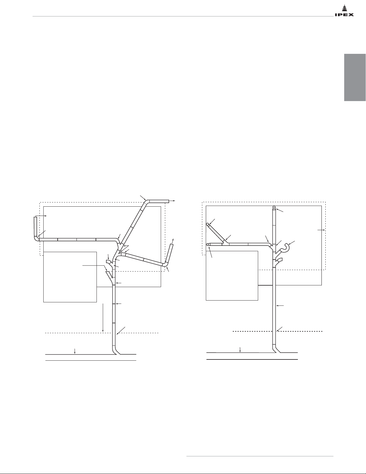
Building Sanitary Drain & Building Storm Drain
For the collection of domestic wastes and storm water
under the concrete slab.
Building Sewer & Building Storm Sewer
For the collection of domestic wastes and storm water
from the building sanitary drain and the building storm
drain for transfer from the foundation to the sewer
lateral or stub line.
Sewer Lateral or Stub Line
For the collection of domestic wastes and storm water
from the building sewer and building storm sewer for
transfer from the property line to the municipal sewer
main and municipal storm sewer.
Wye
Wye
To rain water
leader
bend
bend
bend
bend
Long T urn Tee Wye
bend
Pipe joint coupling
Perimeter
Drain Pipe
bend
Perimeter
Drain
Connection
PORCH
GARAGE
STORM SEWER
LATERAL
STREET LINE
MUNICIPAL STORM SEWER
To RW L
To
RWL
Cleanout
Typical Building Storm Drain & Sewer
Using IPEX PVC Sewer Pipe and Fittings
Adaptor to DWV Stack
Wye
bend
Adaptor to DWV Stack
GARAGE
Wye
Wye
Wye
Adapter to DWV
Stack
Perimeter
Drain Pipe
Floor drain &
P T rap
bend for
cleanout
PORCH
SANITARY SEWER
LATERAL OR STUBLINE
MUNICIPAL SANITARY MAIN
Pipe joint coupling
Typical Building Sanitary Drain & Sewer
Using IPEX PVC Sewer Pipe and Fittings
SECTION ONE: APPLICATIONS
Page 7

2
IPEX PVC Solvent Weld BDS Sewer & Drain Piping Systems
NOTES
Page 8
3
The physical characteristics for plastic pipe in general
are superior to any other material. IPEX PVC pipe offers
high impact resistance, flexible pipe design, bottle
tight joints, smooth non-wetting inner wall surface and
high corrosion resistance. Its smooth inner wall, long
lengths and tight joints result in a greater hydraulic
efficiency and manning flow coefficient of N=0.009.
No other pipe approaches IPEX BDS plastic pipe in
terms of low weight per foot ratio to strength.
Because of these features IPEX BDS pipe:
A. Minimizes breakage and has greater field handling
damage resistance.
B. Flexibility eliminates shear-type failures and absorbs
settling and considerable earth movement.
C. Bottle tight joining method minimizes infiltration,
exfiltration and root infestation problems.
D. Smooth non-wetting surface eliminates build up of
slime, slime bulk, sand contaminates and bacteria
which improves efficiency flow and discharge over
traditional materials of equivalent size for the life of the
sewer.
E. High corrosion resistance eliminates replacement costs
caused by corrosion due to aggressive soil conditions,
bore build up, rot, galvanic conditions and rust.
F. Light weight sections reduce manpower needs, reduce
equipment handling costs, handling and freight cost.
G. Costs less to operate and maintain because it has
greater flow capacity per given size and it is not
affected by sewer gases or sulfuric acid created as byproducts of the hydrogen sulfide cycle or from
aggressive soil conditions.
H.The economic life cycle of a PVC sewer system is
projected at more than 50 years.
Material
Manning
"N" Value
Full Flow Discharge
(GPM)
PVC 0.009 208
Asbestos-Cement 0.013 136
Vitrified Clay 0.013 136
Comparison of "N" Value and Discharge on a 6" Pipe
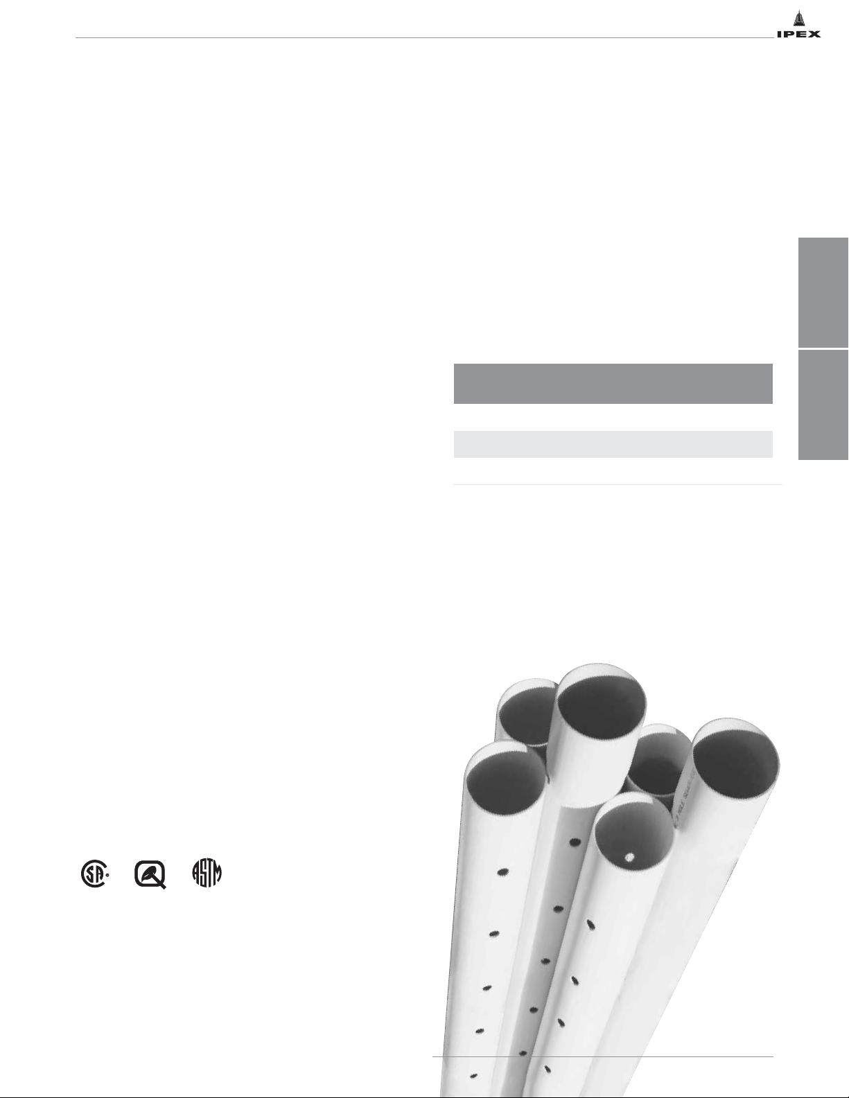
IPEX BDS Sewer Pipe is available in Standard
Spec or third-party certified to CSA B182.1 or
BNQ 3624-050 and conforms to ASTM.
IPEX BDS fittings, made to SDR35 wall, are third party
certified to CSA 182.2 and BNQ 3624-130 and
conform to ASTM D2729.
SECTION TWO: FEATURES & BENEFITS
SECTION THREE: STANDARDS
IPEX PVC Solvent Weld BDS Sewer & Drain Piping Systems
STANDARDS
FEATURES &
BENEFITS
Page 9

4
IPEX PVC Solvent Weld BDS Sewer & Drain Piping Systems
NOTES
Page 10

5
IPEX PVC Solvent Weld BDS Sewer & Drain Piping Systems
SECTION FOUR: SIZES AND DIMENSIONS
Pipe
IPEX BDS Solid Wall Sewer Pipe – Dimensions
Nominal Pipe
Size
(mm)
Average Outside
Diameter
(mm)
Standards
Minimum Wall
Thickness
(mm)
Minimum Stiffness
(kpa)
50 57.1 CSA B182.1 - SDR35 2.06 320
75 82.5 CSA B182.1 - SDR35 2.36 320
100 107.0 CSA B182.1 - SDR35 3.06 320
150 159.4 CSA B182.1 - SDR35 4.55 320
75 82.5 CSA B182.1 - Western Canada 2.36 320
100 107.0 CSA B182.1 - Western Canada 2.92 320
150 159.4 CSA B182.1 - Western Canada 4.35 320
75 82.5 CSA B182.1-SDR38 (Nova Scotia Spec) 2.36 275
100 107.0 CSA B182.1-SDR38 (Nova Scotia Spec) 2.90 275
150 159.4 CSA B182.1-SDR38 (Nova Scotia Spec) 4.19 275
75 82.5 ASTM D2729 1.78 131
100 107.0 ASTM D2729 1.90 76
150 159.4 ASTM D2729 2.54 55
75 82.5 IPEX Standard 1.78 n/a
100 107.0 IPEX Standard 1.91 n/a
150 159.4 IPEX Standard 3.12 n/a
IPEX Perforated Sewer Pipe – Dimensions
Nominal Pipe
Size
(mm)
Average Outside
Diameter
(mm)
Standards
Minimum Wall
Thickness
(mm)
Perforation*
Configuration
Minimum
Stiffness
(kpa)
75 82.5 CSA B182.1 Eastern Canada 2.16 A 200
100 107.0 CSA B182.1 Eastern Canada 2.36 A 200
150 159.4 CSA B182.1 Eastern Canada 3.30 A 200
75 82.5 CSA B182.1 Western Canada 2.02 B 200
100 107.0 CSA B182.1 Western Canada 2.24 B 200
150 159.4 CSA B182.1 Western Canada 2.90 B 200
100 107.0 CSA B182.1 Nova Scotia Spec 2.36 C 200
75 82.5 BNQ 3624-050 2.15 D 200
100 107.0 BNQ 3624-050 3.63 D 200
150 159.4 BNQ 3624-050 3.52 D 200
75 82.5 ASTM D2729 1.78 E 131
100 107.0 ASTM D2729 1.90 E 76
150 159.4 ASTM D2729 2.54 E 55
75 82.5 IPEX Standard 1.78 F n/a
100 107.0 IPEX Standard 1.91 F n/a
150 159.4 IPEX Standard 3.12 F n/a
*See next table
SIZES &
DIMENSIONS
Page 11

6
IPEX PVC Solvent Weld BDS Sewer & Drain Piping Systems
SIZES &
DIMENSIONS
IPEX Perforated Pipe Hole Dimensions
Fittings
A complete line of Solvent Weld Fittings is available for
use with IPEX BDS pipe. They are made from
a tough non-corrosive proprietary compound and they
are free-flowing.
Available configurations include:
Configuration
Type
Primary
Hole Size (mm)
Secondary
Hole Size (mm)
Dimension
X
(mm)
Dimension
Y
(mm)
Angle
f
(Degree)
A 16 13 127 732 120
B 16 none 127 n/a 120
C 16 13 127 3525 120
D 13 9 127 1524 120
E 13 10 127 762 120
F 16 13 118 763 120
• Tees
• Tee-Wyes
• Saddle Tees
• Crosses
• Cleanout Tees
•Wyes
• Saddle Wyes
• Double Wyes
•90oElbows
•45oElbows
•221/2oElbows
• Caps
• Reducer Bushings
• Drain Grates
• Couplings
• Male Adapters
• Female Adapters
• Cleanout Adapters
• Closet Flanges
• Miscellaneous Adapters
Primary
Holes
Secondary
Holes
X
Y
Page 12

7
IPEX PVC Solvent Weld BDS Sewer & Drain Piping Systems
ENGINEERING
DATA
SECTION FIVE: ENGINEERING DATA
Structural Design
PVC pipes are classified as flexible conduits, which
means they are designed to transfer loads to the
bedding envelope surrounding the pipe by deflecting. A
flexible conduit is generally defined as one that can
deflect more than 2% of its diameter without damage.
Perhaps the easiest way to visualize pipe-soil
interaction is to consider the spring analogy that was
used by Dr. A. Moser in his authoritative textbook
“Buried Pipe Design”.
The ability to deflect away from vertical load is what
gives PVC pipe its load carrying capability. The arching
action of the soil over the pipe tends to reduce the
load on the conduit, while the load that is applied is
transferred to the surrounding bedding.
High Load Carrying Capabilities Even with Marginal
Bedding
The pipe-soil system formed by PVC pipe is surprisingly
strong. While PVC pipes are routinely installed with
depths of bury exceeding 50 feet (particularly in
landfill applications), experimental work has shown
that PVC pipe is capable of easily withstanding depths
of bury up to 100 feet. Concrete pipe installed with
identical bedding parameters collapsed. For a complete
research report on this research completed at Utah
State University, please contact your IPEX
representative.
Deflection is Not a Bad Thing
Flexible pipes have a different failure mode than rigid
pipes. Rigid pipes crack and eventually collapse under
excessive load, whereas flexible pipes simply continue
to deflect. PVC sewer pipes can typically deflect up to
30% of their diameter before any leakage occurs at the
joints or damage to the pipe. The deflection limit for a
PVC pipe is typically set at between 5% and 7.5%,
which means that there is a safety factor of between 4
and 6 for deflection.
Rigid pipe manufacturers often point to deflection as a
drawback when using PVC pipe, however this simply
reflects a lack of understanding of the pipe-soil
mechanism. Rigid pipes must also deflect slightly to
carry load, but they respond to this slight deflection by
cracking. As a result, while the performance limit for
flexible pipe is the allowable deflection, the
performance limit for concrete pipe is an allowable
crack width. While concrete pipe manufacturers claim
that their product can “self heal” small cracks, it is
advisable to check these installations with a low
pressure air test to ensure that the cracked pipe is not
leaking.
Flexible pipe is like a spring
P
Δ
P
Δ
P
K = p/Δ F = p/Δ
spring
pipe
E' = p/Δ
soil
Page 13
8
IPEX PVC Solvent Weld BDS Sewer & Drain Piping Systems
ENGINEERING
DATA
Depth
of
Flow
%
Head
of
Water
m
Hole Configuration A
(CSA B182.1)
Hole Configuration B
(CSA 182.1 - West)
Hole
Configuration C
(Nova Scotia)
Hole Configuration D
(BNQ 3624-050)
Pipe Size
75mm
(3")
100mm
(4")
150mm
(4")
75mm
(3")
100mm
(4")
150mm
(5")
100mm 75mm 100mm 150mm
(4") (3") (4") (5")
40 0 19 21 26 17 19 24 20 12 13 16
50 0 24 27 33 22 25 31 26 15 17 21
60 0 28 32 39 26 30 36 30 18 20 24
70 0 31 36 44 29 34 41 34 20 23 28
80 0 35 40 48 33 37 45 38 22 25 31
90 0 38 43 53 35 40 49 41 24 27 33
100 0 40 46 56 38 43 53 44 26 29 36
100 0.1 66 70 77 63 66 73 67 42 44 49
100 0.2 84 87 93 80 83 88 84 54 56 59
100 0.3 99 102 107 94 96 101 98 63 65 68
100 0.4 112 115 119 106 108 113 110 72 73 76
100 0.5 124 126 130 117 119 123 121 79 80 83
100 0.6 135 136 140 127 129 133 131 86 87 89
100 0.7 144 146 150 137 138 142 140 92 93 95
100 0.8 154 155 159 146 147 150 149 98 99 101
100 0.9 162 164 167 154 155 158 157 104 105 106
100 1 171 172 175 162 163 166 165 109 110 112
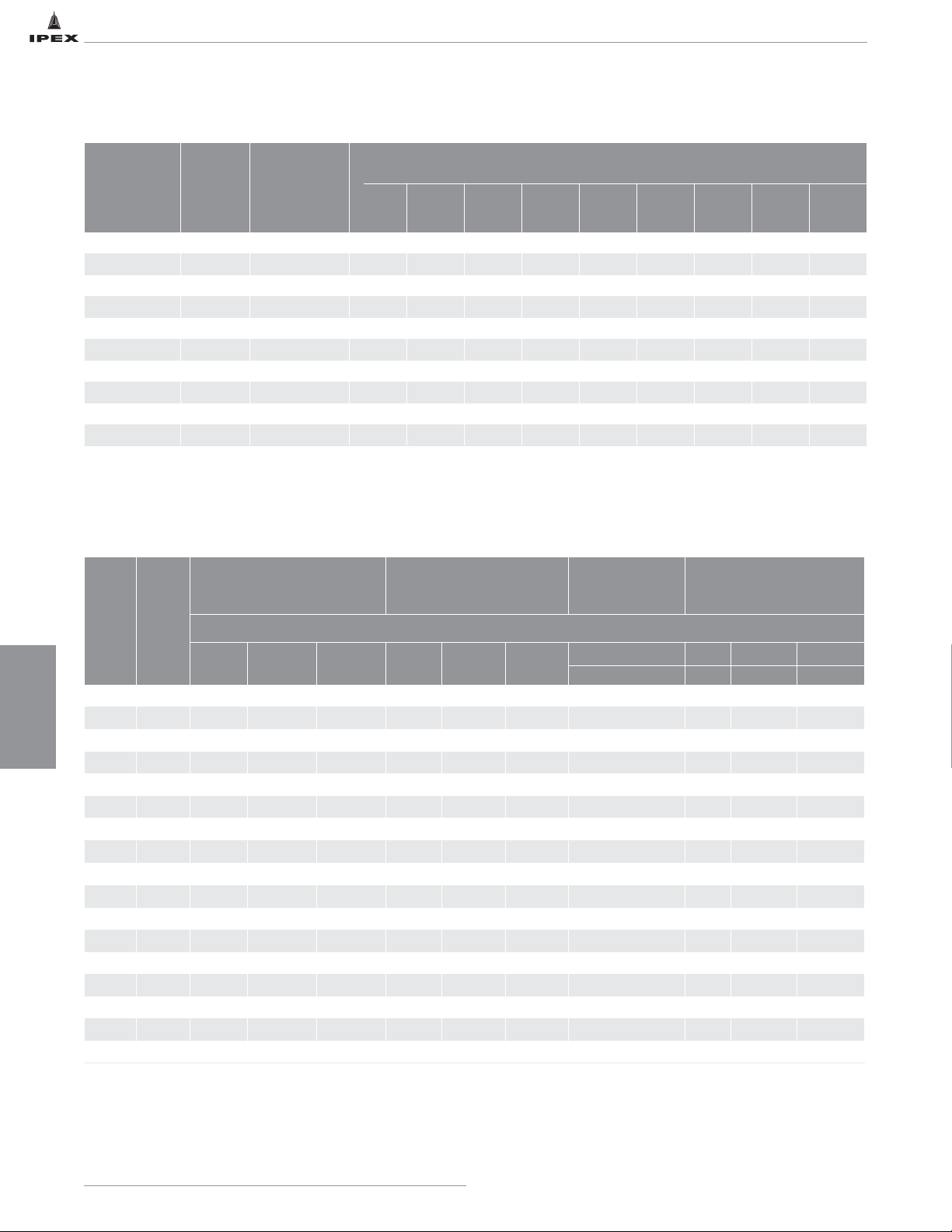
IPEX Perforated Pipe Flow
Flow of water out of pipe through perforations (in liters/minute/foot of pipe length)
Maximum Long Term Deflections of IPEX BDS PVC Sewer Pipe (SDR35)
Pipe Stiffness
FDY
PSI
Bedding
Constant
K
Modulus of Soil
Reaction
PSI
Height of Cover (meters / feet)
0.9 m 1.5 m 2.4 m 3.0 m 3.7 m 4.3 m 4.9 m 5.5 m 6.1 m
3 ft 5 ft 8 ft 10 ft 12 ft 14 ft 16 ft 18 ft 20 ft
Horizontal deflections of pipe (%)
65 .083 200 1.3 2.1 3.4 4.3 5.0 6.0 6.8 7.7 8.5
65 .096 200 1.5 2.5 3.9 4.9 5.9 6.9 7.9 8.9 9.9
65 .110 200 1.7 2.8 4.5 5.7 6.8 7.9 9.0 10.2 11.3
65 .083 400 .8 1.4 2.2 2.7 3.3 3.8 4.4 4.9 5.5
65 .096 400 1.0 1.6 2.5 3.2 3.8 4.4 5.0 5.7 6.3
65 .110 400 1.1 1.8 2.9 3.6 4.4 5.0 5.8 6.5 7.3
65 .083 700 .5 .9 1.4 1.8 2.1 2.5 2.8 3.2 3.6
65 .096 700 .6 1.0 1.6 2.1 2.5 2.9 3.3 3.7 4.1
65 .110 700 .7 1.2 1.9 2.4 2.8 3.3 3.8 4.2 4.7
Note: It is general practice that pipe installation be designed not to exceed 7.5% deflection.
Page 14

9
IPEX PVC Solvent Weld BDS Sewer & Drain Piping Systems
ENGINEERING
DATA
Live Loads
Live loads must at least be considered in underground
pipeline installations where there is the potential for
vehicle traffic. Live loads have little or no effect except
in shallow burial. However, in extremely shallow
installations PVC sewer pipe will react to high live
loads by deflecting additionally and then will return to
its original shape. Where PVC sewer pipe is installed
with less than three feet of cover under roads, special
design may be required.
Theoretical Load Distribution in Buried PVC Pipe
Vertical Load
Vertical Reaction
Side Fill
Soil Reaction
Side Fill
Soil Reaction
Beddng
Grace
Impact Resistance in Ft/lbs for IPEX BDS Sewer Pipe
(SDR35)
Size
(mm)
CSA
Minimum
IPEX Typical Results
0ºC 23ºC 0ºC -23ºC
100 70 160 150 140
150 110 365 340 305
* where there is the potential for vehicle traffic.
Page 15

10
IPEX PVC Solvent Weld BDS Sewer & Drain Piping Systems
NOTES
Page 16

11
IPEX PVC Solvent Weld BDS Sewer & Drain Piping Systems
SECTION SIX: INSTALLATION
Excavation and Pipe Laying
Care should be taken during excavation of trench to
provide as narrow a trench as practical at a point level
with the top of the pipe. The usual is the diameter of
the pipe plus 18" to 24". If it becomes necessary to
construct a trench wider than usual, it is recommended
that the pipe be installed in a
sub-trench to minimize earth load (See Diagrams
below). The pipe should be bedded true to line and
grade with uniform and continuous support from a firm
base. Blocking shall not be used to bring the pipe to
grade. If unstable soil conditions or rock conditions are
encountered the trench bottom should be overexcavated and brought to grade with suitable bedding
material.
Bedding, Haunching and Initial Backfill
a) With installations involved on private property where the
Provincial Plumbing Inspector is responsible then the
local plumbing code regulation should be followed.
b) With installation involved on municipal property where
the municipality itself is responsible then IPEX suggests
that the engineer specify bedding material and
installation techniques as outlined in
ASTM D 2321. Recommended practice
for underground installation of flexible thermoplastic
sewer pipe.
Final Backfill
The material that completes the backfilling is usually
placed in the trench by machine. Care should be
taken, however, to avoid large stones, frozen clumps of
dirt, etc. One should also ensure that the initial
backfill be selected and tamped by hand and be at a
minimum of 12" above the top of the pipe.
Trench Construction
1500 lbs.
(per lin. ft.)
1500 lbs.
(per lin. ft.)
1500 lbs.
(per lin. ft.)
28" 28" 28"
33" 36" 42"
1900 lbs.
(per lin. ft.)
2100 lbs.
(per lin. ft.)
2500 lbs.
(per lin. ft.)
If width is increased at pipe level, the earth load on the
pipe will be greater.
INSTALLATION
Page 17

12
IPEX PVC Solvent Weld BDS Sewer & Drain Piping Systems
SOLVENT
WELDING
SECTION SEVEN: SOLVENT WELDING
The solvent welded connection in thermoplastic pipe
and fittings is the last vital step in a plastic pipe
installation. It can mean the success or failure of the
system as a whole. Accordingly, it requires the same
professional care and attention that is given to other
components of the system.
For complete information on solvent welding, please
consult our Solvent Welding Guide. www.ipexna.com
Page 18
13
IPEX PVC Solvent Weld BDS Sewer & Drain Piping Systems
SECTION EIGHT: LEACHING BEDS (SEPTIC TANK SYSTEMS)
What a septic tank system does
A septic tank system returns household sewage and
other liquid wastes to the soil so that they do not
appear on the surface or pollute ground water. It
consists of the tank itself which settles out solid
wastes and prepares the sewage for absorption by the
soil, plus perforated pipe which distributes effluent
evenly in a series of trenches called a leaching bed.
Septic tank location is important
Local codes and standards must be consulted before
siting any septic system. In general, septic tanks must
be located where there is no possibility of
contaminating any water supply source. Because
contamination can travel a long way underground and
in any direction, it is imperative that a septic tank be
located downhill sufficiently far from any water supply
to meet local health regulations.
Do not under any circumstances locate the septic tank
any closer than five feet from a building or structure; or
50 feet from any water source-well, spring, stream,
river, pond or lake.
Planning and placing the leaching bed
The series of trenches which constitute the leaching
bed is intended to accommodate the distribution of
pipe and absorb the effluent. The trench footage
required depends upon the size of the house and the
soil conditions where the bed will be located.
Choice of distribution pipe is important. It must
distribute the effluent evenly along the entire length of
each absorption trench. The use of field tile in
absorption trenches results in early distribution, while
two-hole plastic pipe has the opposite effect. In each
case it means that only a small area of the leaching
bed is being utilised at any given time.
The use of two-hole plastic pipe and corrugated tubing
also allows secondary settlement of solid content. This
can result in a serious slime build up, with the
eventual sealing of all pipe perforations, section by
section, and finally complete immobilization of the
leaching bed.
IPEX three-hole perforated pipe has been engineered to
give even distribution and thus eliminate trench failure
by overloading due to early (progressive failure) or late
(regressive failure) distribution of effluent from the
header. The spacing of the third hole is critical. Too
close will result in progressive failure, too far apart the
effluent will not be distributed evenly.
Locating the leaching bed
A leaching bed should not be located any closer than
10 feet from a building, structure or property
boundary; 25 feet from a building or structure where
the bottom of the distribution pipe is on the same level
or above the level of the lowest floor in the building or
structure; 50 feet from any lake, river, pond, spring,
stream, reservoir or drilled well with water-tight casing
to a depth of 20 feet; or 100 feet from a dug well.
In every case, it is essential to check with local
authorities for verification.
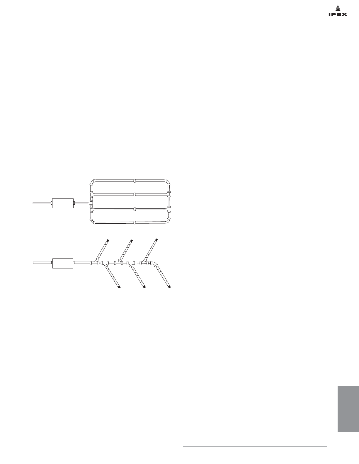
Septic T ank
Septic T ank
4" Solid Pipe for
connecting and
header pipe
4" Solid
header pipe
Fittings
Minimum 6' width
Perforated pipe
Perforated
pipe
Capped
ends
Typical Leaching Bed Layouts
LEACHING BEDS
Page 19
14
IPEX PVC Solvent Weld BDS Sewer & Drain Piping Systems
LEACHING BEDS
Pre-testing leaching bed location
A percolation test will determine the footage of
absorption trench and distribution pipe required for the
leaching bed. This is how it is done:
a) Dig a hole, where the bed is to be located, between four
and 12" in diameter, and as deep as the bottom of the
bed.
b) Remove all loose material and smeared clay from the
bottom and sides of the hole, and cover the bottom with
two inches of sand or fine gravel.
c) Pour clear water into the hole to a depth
of at least 12". Add more water as needed
to maintain the 12" depth until the surrounding soil
becomes saturated and the water being added seeps
away at a constant rate.
d) Determine the average percolation time in minutes
required for the water level to drop one inch.
Estimating Distribution Pipe Required
The following table indicates the minimum length of
distribution pipe required for various leaching bed
areas, depending on the percolation times and the
number of bedrooms in the dwelling:
No. of
Bedrooms
Percolation
Time
Length of
Pipe
(min) (ft)
2 or less 1-5 150
3 1-5 150
4 1-5 180
2 or less 5-10 150
3 5-10 200
4 5-10 250
2 or less 10-20 180
3 10-20 300
4 10-20 350
2 or less 20-30 220
3 20-30 350
4 20-30 450
2 or less 30-40 250
3 30-40 400
4 30-40 500
2 or less 40-50 300
3 40-50 450
4 40-50 550
2 or less 50-60 350
3 50-60 500
4 50-60 650
Page 20
15
IPEX PVC Solvent Weld BDS Sewer & Drain Piping Systems
LEACHING BEDS
Excavating Absorption Trenches
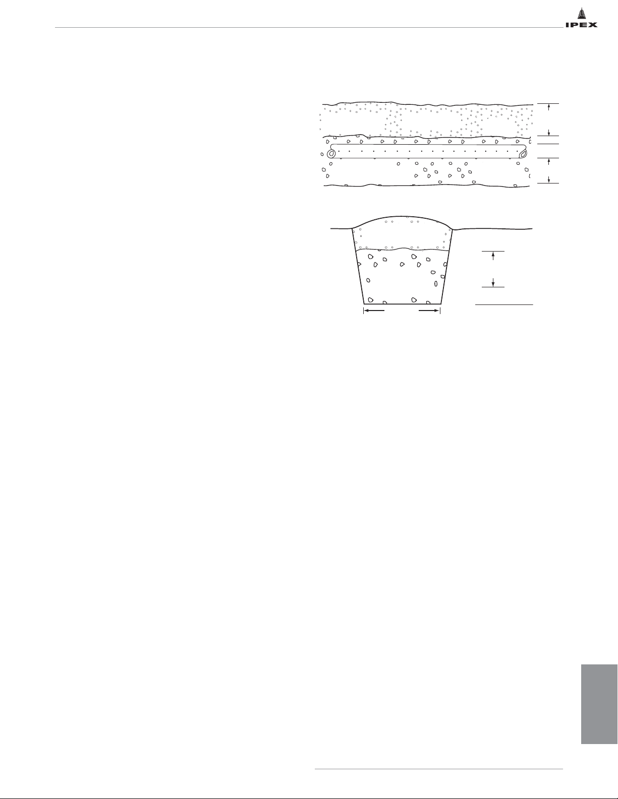
In digging leaching bed trenches, the following rules
should be observed:
• Obtain copy of local sewage system regulations for full
details on installing a septic tank system in the area.
• Make the trenches at least 18" wide and 25" to 36"
deep.
• Locate distribution pipes approximately
6 feet apart.
• Provide distribution pipes with a uniform slope of not
less than four inches and not more than six inches for
every 100 feet of length. If a siphon or pump is used, a
3" to 4" slope will suffice.
• Fill the full width of each trench bottom with six inches
of clean gravel between ¾" to 2 ½" size or crushed
stone ¾" in size, free of fine material.
• When laid, cover the distribution pipes with clean,
screened gravel or crushed stone to a depth of 2" above
the top of the pipe.
• Lay untreated building paper, pea gravel or straw on top
of the gravel covering the pipe to prevent soil from
entering it.
• Backfill the distribution trenches with porous sandy
loam or top soil to prevent depressions after settlement.
IPEX recommends CSA certified Pipe. The higher physical
values of certified pipe as compared with non-certified
pipe make the few cents per foot extra cost well
worthwhile. Remember, the CSA seal is a policed
specification, and your assurance of piping quality.
12" - 23"
Varies
2" min
4" Approx.
6" min
Stone or
Gravel Surroung
Earth Backfill
Pipe
Cover
1/4" Crushed
Stone or
1/4" - 2 1/2" Gravel
Gravel Bed
6" Approx.
12" - 23"
Varies
6" min
25" - 36" Varies
Earth Backfill
(Sandy loam or topsoil)
Gravel Bed
18" - 36"
Page 21

16
IPEX PVC Solvent Weld BDS Sewer & Drain Piping Systems
ADAPTER CHART TO CONVENTIONAL MATERIALS
IPEX BDS BDS Adapters
Spigot
2", 3" or 4"
Hub
4" or 5"
Gasket
4" or 5"
Spigot
4", 5" or 6"
ABS Spigot Adapter
PVC Adapter
4" or 5"
ABS Bushing
PVC - A/C Adapter
5" x 4", 4" x 3"
4" x 2" or 4" x
2", 3" or 4"
ABS Bushing
5" x 4", 4" x 3"
4" x 2" or 4" x 1
11/2"
Asbestos Cement / Crowle "O" Ring
4", 5", 6"
or 4" x 5"
Conventional
Pipe Materials
ABS / DWV
Hub
2", 3" or 4"
Spigot
1
1
1
/2"
/2", 2", 3" or 4"
Spigot
1
1
/2", 2", 3" or 4"
A/C - Machined End
4", 5" or 6"
Spigot
4", 5" or 6"
Spigot
4"
Spigot
4", 5" or 6"
Spigot
2", 3", 4", 5" or 6"
PVC Gasket - A/C
Coupling or Crowle
"O" Ring Adapter
PVC S.W. - A/C
Coupling or Crowle
"O" Ring Adapter
Rubber Bushing
4", 5" or 6"
Cast Iron Coupling
4", 5", 6"
4"
Clay Pipe Coupling
4", 5" or 6"
2", 3", 4", or 6"
A/C Coupling or Crowle
"O" Ring 4", 5" or 6"
A/C Coupling or Crowle
"O" Ring 4"
Vitrified Clay
Clay Pipe
4", 5" or 6"
Cast Iron
Cast Iron - Plain End
2", 3", 4", or 6"
Page 22

This literature is published in good faith and is believed to be reliable.
However, it does not represent and/or warrant in any manner the information
and suggestions contained in this brochure. Data presented is the result of
laboratory tests and field experience.
A policy of ongoing product improvement is maintaned. This may result
in modifications of features and/or specifications without notice.
MNMEBDIP160504C
© 2016 IPEX MS0032C
SALES AND CUSTOMER SERVICE
Canadian Customers call IPEX Inc.
Toll Free: (866) 473-9462 (IPEX INC)
ipexna.com
About the IPEX Group of Companies
As leading suppliers of thermoplastic piping systems, the IPEX Group of
Companies provides our customers with some of the largest and most
comprehensive product lines. All IPEX products are backed by more than
50 years of experience. With state-of-the-art manufacturing facilities and
distribution centers across North America, we have established a reputation
for product innovation, quality, end-user focus and performance.
Markets served by the IPEX Group of Companies include:
• Electrical systems
• Telecommunications and utility piping systems
• Industrial process piping systems
• Municipal pressure and gravity piping systems
• Plumbing and mechanical piping systems
• PE Electrofusion systems for gas and water
• Industrial, plumbing and electrical cements
• Irrigation systems
• PVC, CPVC, PP, PVCO, ABS, PEX, FR-PVDF, NFRPP, FRPP, HDPE, PVDF
and PE pipe and fittings (1/2" – 48")
Products manufactured by IPEX Inc.
 Loading...