

Page 1

iPECS SBG-1000
Quick Start Guide
Please read this manual carefully before operating System.
Retain it for future reference.
Page 2

iPECS SBG-1000 Quick Start Guide
Regulatory and Safety Notices
Before connecting the Smart Business gateway to the telephone network, you may be required to notify your local
serving telephone company of your intention to use "customer provided equipment.” You may further be required to
provide any or all of the following information:
PSTN line Telephone numbers to be connected to the system
Model name: Smart Business gateway
Local regulatory agency registration number: locally provided
Registered jack: RJ-45
The required regulatory agency registration number is available from your local Aria Technologies Africa
representative.
If the telephone company determines that customer provided equipment is faulty and may possibly cause harm or
interruption in service to the telephone network, it should be disconnected until repair can be affected. If this is not
done, the telephone company may temporarily disconnect your service.
The local telephone company may make changes in its communications facilities or procedures. If these changes
could reasonably be expected to affect the use of the Smart Business gateway or compatibility with the network, the
telephone company is required to give advanced written notice to the user, allowing the user to take appropriate steps
to maintain telephone service.
The Smart Business gateway complies with rules regarding radiation and radio frequency emission as defined by
local regulatory agencies. In accordance with these agencies, you may be required to provide information such as the
following to the end user:
WARNING
This equipment generates and uses R.F. energy, and if not installed and used in accordance with
the Instruction Manual, it may cause interference to radio communications. It has been tested and
found to comply with the appropriate limits for a telecommunication device. The limits are designed
to provide reasonable protection against such interference, when operated in a commercial
environment.
Operation of this equipment in a residential area could cause interference, in which case the user, at
his own expense, will be required to take whatever measures may be required to correct the
interference.
1. Radio Frequency Emissions:
FCC Compliance statement:
This device complies with Part 15 of the FCC rules. Operation is subject to the following conditions;
(1) This device may not cause harmful interference.
(2) This device may accept any interference received, including interference that may cause undesired operation.
This Equipment has been tested and found to comply with the limits for a Class B digital device, pursuant
to Part 15 of the FCC rules. These limits are designed to provide reasonable protection against harmful
interference in a residential installation. This equipment generates, uses and can radiate radio frequency
energy and, if not installed and used in accordance with the instructions, may cause harmful interference to
radio communications. However, there is no guarantee that interference will not occur in a particular
installation. If this equipment does cause harmful interference to radio or television reception, which can
be determined by turning the equipment off and on, the user is encouraged to try to correct the interference
by one of the following measures:
• Reorient or relocate the receiving antenna.
• Increase the separation between the equipment and the receiver.
• Connect the equipment into an outlet on a different circuit from that to which the receiver is connected.
If problems persist, consult the dealer or an experienced radio/TV technician for help.
Page 3
iPECS SBG-1000 Quick Start Guide
Canadian Compliance statement:
This Class B digital apparatus complies with Canadian ICES-003.
Cet appareil numérique de la classe B est conforme à la norme NMB-003 du Canada.
This device complies with Class B limits of Industry Canada. Operation is subject to the following two
conditions;
1. This device may not cause harmful interference, and
2. This device must accept any interference received, including interference that may cause undesired
operation.
Any changes or modifications in construction of this device which are not expressly approved by
the party responsible for compliance could void the user's authority to operate the equipment.
European Union Declarations of Conformity:
Aria Technologies Africa (Pty) Ltd. declares that the equipment specified in this document, which bears the
“CE” mark, conforms to the European Union Radio and Telecommunications Terminal Equipment Directive
(R&TTE 1999/5/EC) including,
Electromagnetic Compatibility Directive (2004/108/EEC) and
Low Voltage Directive (2006/95/EEC)
The product fulfills the essential requirements of the harmonized standards shown above.
2. Product Safety Instructions
This product complies with and conforms to the following international Product Safety standards as
applicable:
Safety of Information Technology Equipment, IEC 60950-1, including
Relevant national deviations as listed in Compliance with IEC for Electrical Equipment (IECEE)
Safety of Information Technology Equipment, CAN/CSA-C22.2 No. 60950-1/UL 60950-1
3. Privacy:
This multi-line telephone system (MLTS) implements security and encryption technologies appropriate for
DECT however, privacy of communications may not be ensured when using this telephone.
4. RF Exposure Statement:
This equipment complies with FCC/IC RF radiation exposure limits set forth for an uncontrolled
environment. Use of other accessories may not ensure compliance with FCC/IC RF exposure guidelines.
This device must not be co-located or operating in conjunction with any other antenna or transmitter. The
changes or modifications not expressly approved by the party responsible for compliance could void the
user’s authority to operate the equipment.
5. Base Station :
This equipment complies with FCC/IC RF radiation exposure limits set forth for an uncontrolled
environment. This equipment should be installed and operated with a minimum distance of 20 centimeters
between the radiator and your body.
This system employs a Lithium battery as back-up power for the real-time clock and memory. The battery is
not replaceable in the field. RISK OF EXPLOSION IF BATTERY IS REPLACED BY AN INCORRECT TYPE.
Dispose of used batteries accordance with the manufacturer’s instructions.
Page 4

iPECS SBG-1000 Quick Start Guide
Regarding Telephone line cord in USA and Canada : To reduce the risk of fire, use only No. 26 AWG or larger (e.g.,
24 AWG) UL Listed or CSA Certified Telecommunication Line Cord.
Disposal of old appliance
1. When this crossed-out wheeled bin symbol is attached to a product it means the
product is covered by the European Directive 2012/19/EC.
2. All electrical and electronic products should be disposed of separately from the
municipal waste stream via designated collection facilities appointed by the
government or the local authorities.
3. The correct disposal of your old appliance will help prevent potential negative
consequences for the environment and human health.
4. For more detailed information about disposal of your old appliance, please contact your
city office, waste disposal service or the shop where you purchased the product.
Page 5

iPECS SBG-1000 Quick Start Guide
I
Table of Contents
1 SYSTEM OVERVIEW ........................................................................... 1
1.1 iPECS SBG-1000 Network Connection Diagram ...................................... 1
1.2 PSTN Back-up Types ................................................................................... 2
1.3 Installation of PSTN Back-up ...................................................................... 2
2 INSTALLATION .................................................................................... 3
2.1 Cell Coverage ............................................................................................... 3
2.2 General Guidelines ...................................................................................... 3
2.3 Unpacking ..................................................................................................... 4
2.4 Wall Mounting/ Wiring Arrangement ......................................................... 5
2.4.1. Wall Mounting ............................................................................................................ 5
2.4.2. Wiring Arrangement ................................................................................................... 5
3 SPECIFICATIONS ................................................................................ 6
3.1 General Specifications ................................................................................ 6
3.2. System Capacity ......................................................................................... 7
4 CONNECTIONS.................................................................................... 8
4.1 Connections ................................................................................................. 8
4.1.1 Connection for AC/DC adapter ................................................................................... 8
4.1.2 Connections for LAN/ WAN/ PSTN Back-up .............................................................. 9
5 FUNCTION BUTTONS / LED ICONS / LEDS ................................... 13
5.1 Function Buttons / LED Icons / LEDs ...................................................... 13
5.1.1 Function Buttons ....................................................................................................... 13
5.1.2 LED Icons ................................................................................................................. 14
5.1.3 LEDs ..................................................................................................................... 15
6 STARTING IPECS SBG-1000 ............................................................ 16
6.1 Installation Wizard ..................................................................................... 16
6.1.1 Step 1: Test Ethernet Link ........................................................................................ 17
6.1.2 Step 2: Analyze Internet Connection Type ............................................................... 17
6.1.3 Step 3: Setup Internet Connection ........................................................................... 18
6.1.4 Step 4: Test Service Provider Connection ............................................................... 19
6.1.5 Step 5: Test Internet Connection .............................................................................. 19
6.1.6 Step 6: Wireless Setup ............................................................................................. 20
6.1.7 Step 7: Installation Completed .................................................................................. 22
Page 6

iPECS SBG-1000 Quick Start Guide
II
7 TROUBLESHOOTING ....................................................................... 23
Page 7
iPECS SBG-1000 Quick Start Guide
1
1 SS
YYSSTTEEMM
O
O
VVEERRVVIIEEW
W
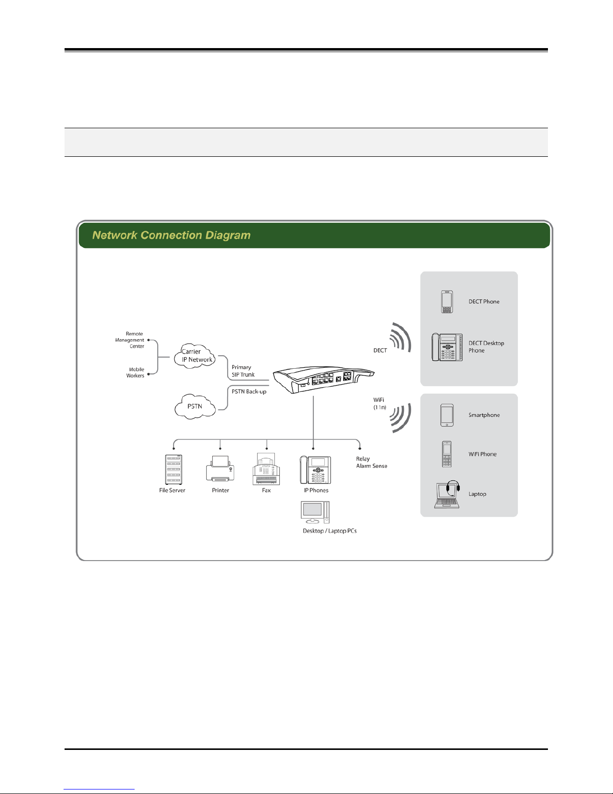
1.1 iPECS SBG-1000 Network Connection Diagram
iPECS SBG-1000 (Smart Business Gateway-1000)
iPECS SBG-1000 is all-in-one mult i -service communication solution via single Inter net con nec ti on f or smal l
businesses.
The following figure shows the components that make up the iPECS SBG-1000 system.
Figure 1.1 Network Connection Diagram
Page 8
iPECS SBG-1000 Quick Start Guide
2
1.2 PSTN Back-up Types
PSTN Back-up functions can be supported with ONLY one of the following daugh t er b o ard types assembled from t he
factory.
Daughter board types for PSTN Back-up
Resources
Remark
CIU1/ CIU2/ CIU4 installed in iPECS SBG-1000
1 or 2 or 4 CO Port
CO Interface Uni t
BRIU/ BRIU2 installed in iPECS SBG-1000
1 or 2 BRI Port (2B + D)
Basic Rate Int erface Unit
CSIU installed in iPECS SBG-1000
1 CO & 1 SLT Port
CO & SLT Interfa ce U nit
In the event of a power failure, the 1
st
CO port is automatically connected to SLT port as basic s o t hat th e sy s tem
works for PFT (Power Failure Transfer).
1.3 Installation of PSTN Back-up
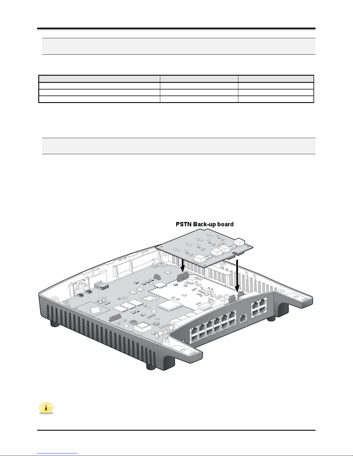
PSTN Back-up can be optionally mounted on iPECS SBG-1000 sy stem.
To install PSTN Back-up board, perform the following Steps:
1. Remove the scr ews.
2. Open the cover c ar efully.
3. Install PSTN Back-up board.
Figure 1.2 Board installation
Note: The system must need to reset to Default after PSTN Back-up installation.
Page 9

iPECS SBG-1000 Quick Start Guide
3
2 II
NNSSTTAALLLLAATTIIOON
N
2.1 Cell Coverage
In a typical offi ce en vi ronm e nt wher e t her e ar e s om e obs t acl es, th e co ver ag e ar ea o f th e iPECS SBG-1000 cell is
approximately 15 ~ 30 meters. A better coverage distance could be achieved in more open areas. The coverage area
is, however, truly dependent on the office environment characteristics (e.g. construction material of walls, metallic
objects, doors, windows, stair-wells, etc). Other radio equipment such as DECT phones or WIFI equipment could als o
affect the cover ag e ar e a. Th e c over a ge ar ea w il l be u ni que f or eac h of fic e e nvi r onm ent .
2.2 General Guidelines
1. Try to locate the iPECS SBG-1000 in such a way to maximize the direct line of sight between the wireless
terminals and the iPECS SBG-1000 antenna.
2. Try to minimize obstructions near the antenna of iPECS SBG-1000.
3. Where possible, centralize the SBG-1000 within the desired coverage area that you intend to cover.
4. In an office environment, consider the office furniture in order to minimize reflection, diffraction and
scattering of the DECT/Wi-Fi radio waves when you choose the position of the iPECS SBG-1000.
5. Try not to locate the iPECS SBG-1000 on top of any steel furniture.
6. Electronic equipment such as a copy machine, a printer or a computer might have an influence on the
coverage area.
7. Try to locate the iPECS SBG-1000 in an open area as high as possible. Avoid areas such as high traffic
areas, corners and narrow walkways.
8. When moving around while busy on a wi reless handset, you may experience degradation in speech quality
(e.g. breaking up of speech). If this happens, rather stand still during the call.
Page 10
iPECS SBG-1000 Quick Start Guide
4
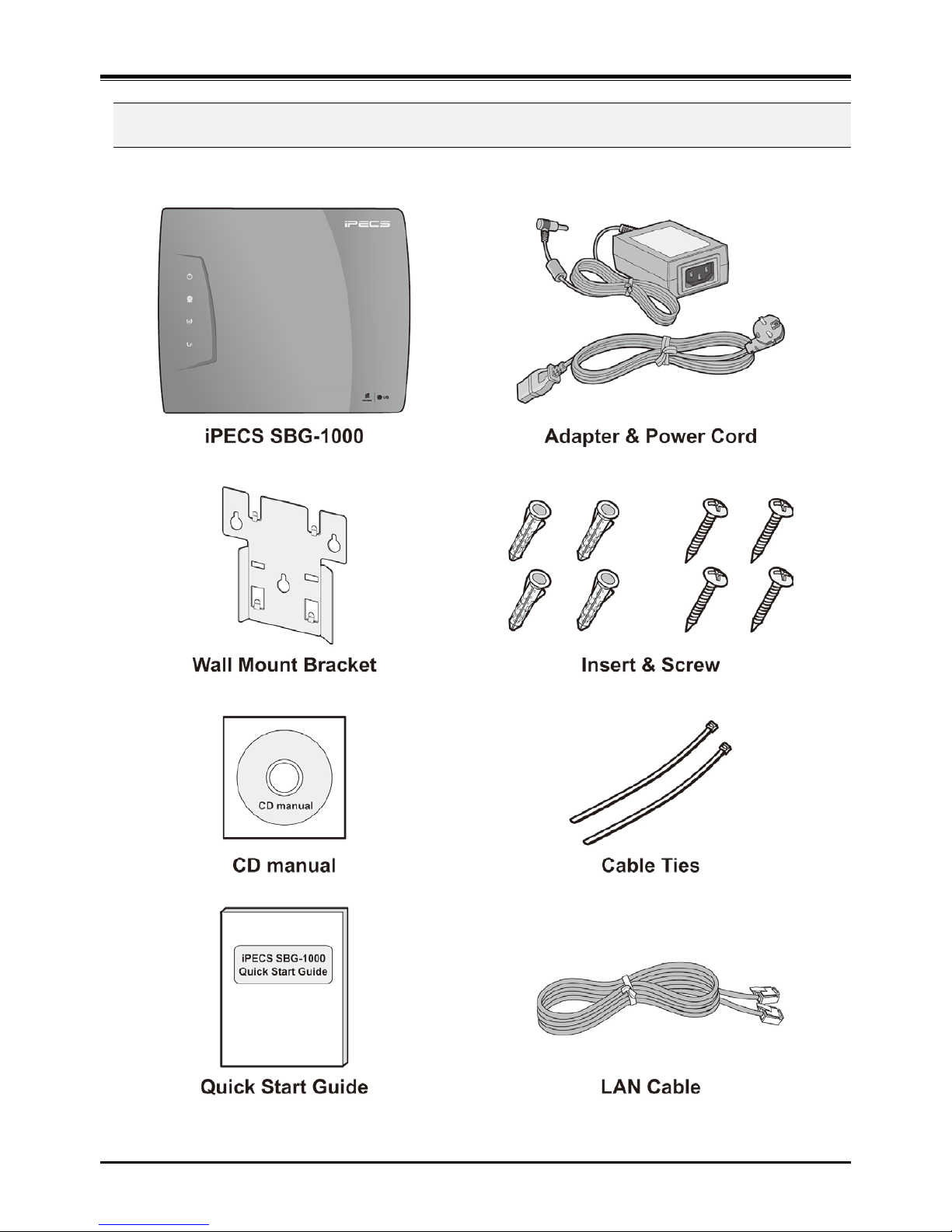
2.3 Unpacking
Open the box and verify the items shown in the following figure are included:
Figure 2.3 iPECS SBG-1000 Carton Contents
Page 11
iPECS SBG-1000 Quick Start Guide
5
2.4 Wall Mounting/ Wiring Arrangement
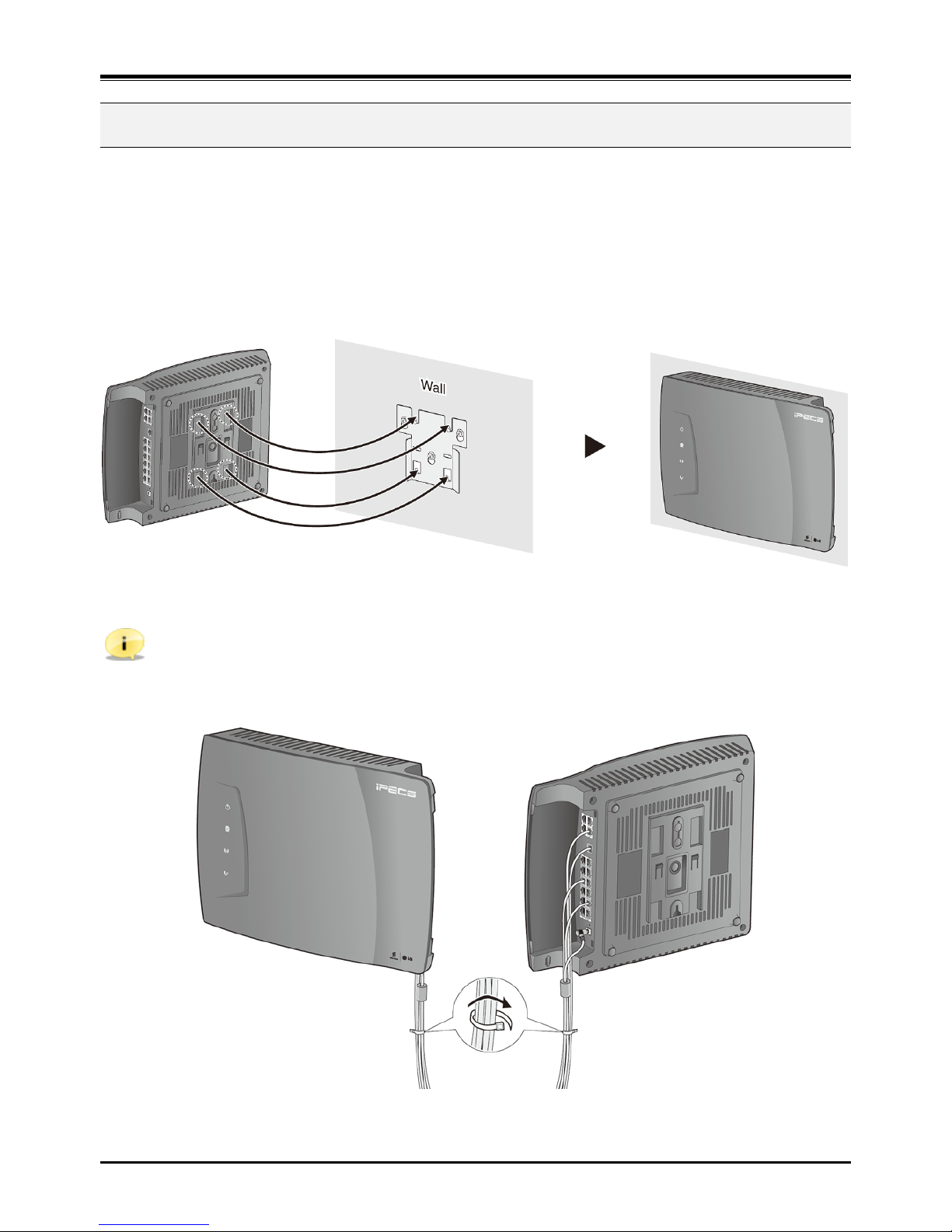
2.4.1. Wall Mounting
1. Install the wall mount br ac ket to t h e wall an d dr il l th e hol e.
2. Install 3 anchor plugs into the wall.
3. Insert 3 included screws into the 3 anchor plugs.
4. Install the iPECS SBG-1000 sys tem to t he w all mo unt br ack et .
Figure 2.4.1 Wall Mounting
Note: Basically, ERICSSON-LG recommends the wall mounting installation for better wireless characteristics.
2.4.2. Wiring Arrangement
Figure 2.4.2 Wiring Arrangement
Page 12

iPECS SBG-1000 Quick Start Guide
6
3 SS
PPEECCIIFFIICCAATTIIOONNS
S
3.1 General Specifications
3.1.1 Dimension and Weight
ITEM
HEIGHT(mm)
WIDTH(mm)
DEPTH(mm)
WEIGHT(g)
iPECS SBG-1000 System (with CIU4 Back-up)
34
278
233
842 (895)
3.1.2 Environment
ITEM
DEGREES (℃)
DEGREES (℉)
Operation Temperature
0~40
32~104
Optimum Oper atio n Tem p er atur e
20~26
68~78
Storage Temper at ur e
10~70
32~158
Relative Humidity
0~80% non-condensing
3.1.3 AC/DC Power Adapter
Electrical SPECIFICATION
AC Input
100 ~ 240 Volt AC @50/60Hz, 1A Max.
DC Output
DC48V, 0.8A Max., 38.4W
3.1.4 SLT (Basic SLT or CSIU)
ITEM
SPECIFICATION
Connector
RJ-45 Modular Jack
Loop Distance
1.5 km with AWG24
Caller Identification (CID)
FSK (ITU-T V.23 or Bell 202) or DTMF (ITU-T Q.23)
Ring Capacity / Frequency
60Vrms (up to 3 REN)/ 25Hz
3.1.5 CO (CIU1 or CIU2 or CIU4 or CSIU)
ITEM
SPECIFICATION
Connector
RJ-45 Modular Jack
Interface type
Loop Start CO, Caller Identification (CID) Detection
3.1.6 BRI (BRIU or BRIU2)
ITEM
SPECIFICATION
Connector
RJ-45 Modular Jack
Maximum Wiring Distance
1000 m (Point t o Point) / 200 ~ 500 m (Point to Multi-point)
3.1.7 Ethernet (LAN port 1 ~ LAN port 8)
ITEM
SPECIFICATION
Connector
RJ-45 Modular Jack
LAN Interface
10/100 BASE-T (Auto-Negotiation), 10 Mbps or 100 Mbps, IEEE 802.3
Maximum Wiring Distance / Cable
100 m/ 0.328 kft, Category 5 UT P Cable
Page 13
iPECS SBG-1000 Quick Start Guide
7
3.1.8 Ethernet (WAN port)
ITEM SPECIFICATION
Connector RJ-45 Modular Jack
WAN Interface 10/100/1000 BASE-T (Auto-Negotiation), 10 Mbps or 100 Mbps or
1000 Mbps, IEEE 802.3/ IEEE 802.3ab/ IEEE 802.3az
Maximum Wiring Distance / Cable 100 m/ 0.328 kft, Category 5e UTP Cable for 1000 Mbps
3.1.9 PoE (LAN port 1 ~ LAN port 4 only, LAN port 5 ~ LAN port 8 are not supported)
ITEM SPECIFICATION
Interface Specification IEEE 802.3af (Total PoE Budgets : 20 W, 5W/Port)
Note: You should use the standard external AC/DC adapter for Class 3 IP Terminals.
3.1.10 WiFi
ITEM SPECIFICATION
Interface Specification / Frequency IEEE 802.11 b/g/n (Draft 2.0), 2x2 MIMO, 2.412GHz ~ 2.472GHz
Note: Basically, ERICSSON-LG recommends the wall mounting installation for better wireless characteristics.
3.1.11 DECT
ITEM SPECIFICATION
Frequency 1,880MHz ~ 1,900MHz for Europe
1,920MHz ~ 1,930MHz for US
Note: Basically, ERICSSON-LG recommends the wall mounting installation for better wireless characteristics.
3.1.12 USB
ITEM SPECIFICATION
Interface Specification USB V 1.1 & V2.0, Host Mode
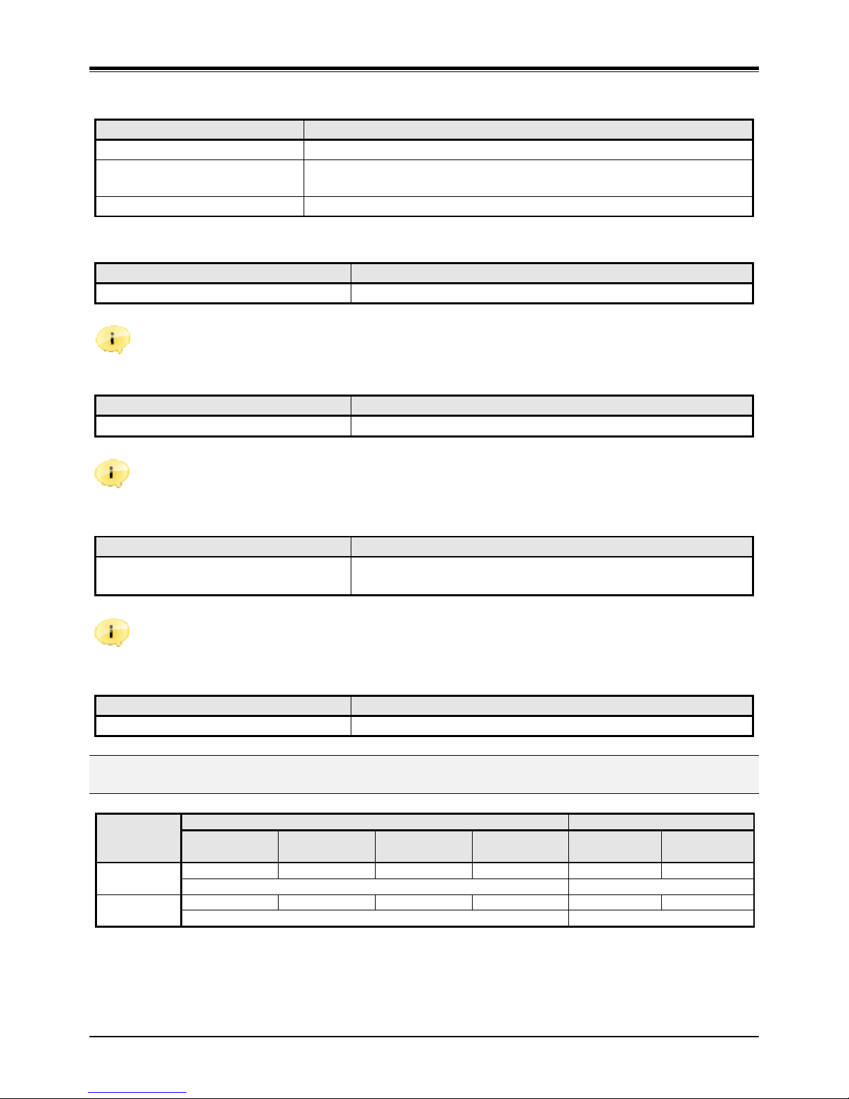
3.2. System Capacity
Extension Trunk
LIP
Phones
SLT SIP
Phones
DECT SIP PSTN
Back-up
Total
(Basic)
11 1 or 2 6 6 3 1 or 2 or 4
12 4 or 5 or 7
Total
(Extended)
23 1 or 2 6 6 4
N1)
or 6 1 or 2 or 4
24 5 or 6 or 8 / 7 or 8 or 10
N1) The number of VoIP Trunk when DECT module is enabled.
* PSTN Back-up function using CIU1/ CIU2/ CIU4/ BRIU/ BRIU2/ CSIU daughter board.
* DECT Specification: 4 Simultaneous Calls, 6 Registrations
* Lock key is required for system capacity extended.
Page 14
iPECS SBG-1000 Quick Start Guide
8
4 CC
OONNNNEECCTTIIOONNS
S
4.1 Connections
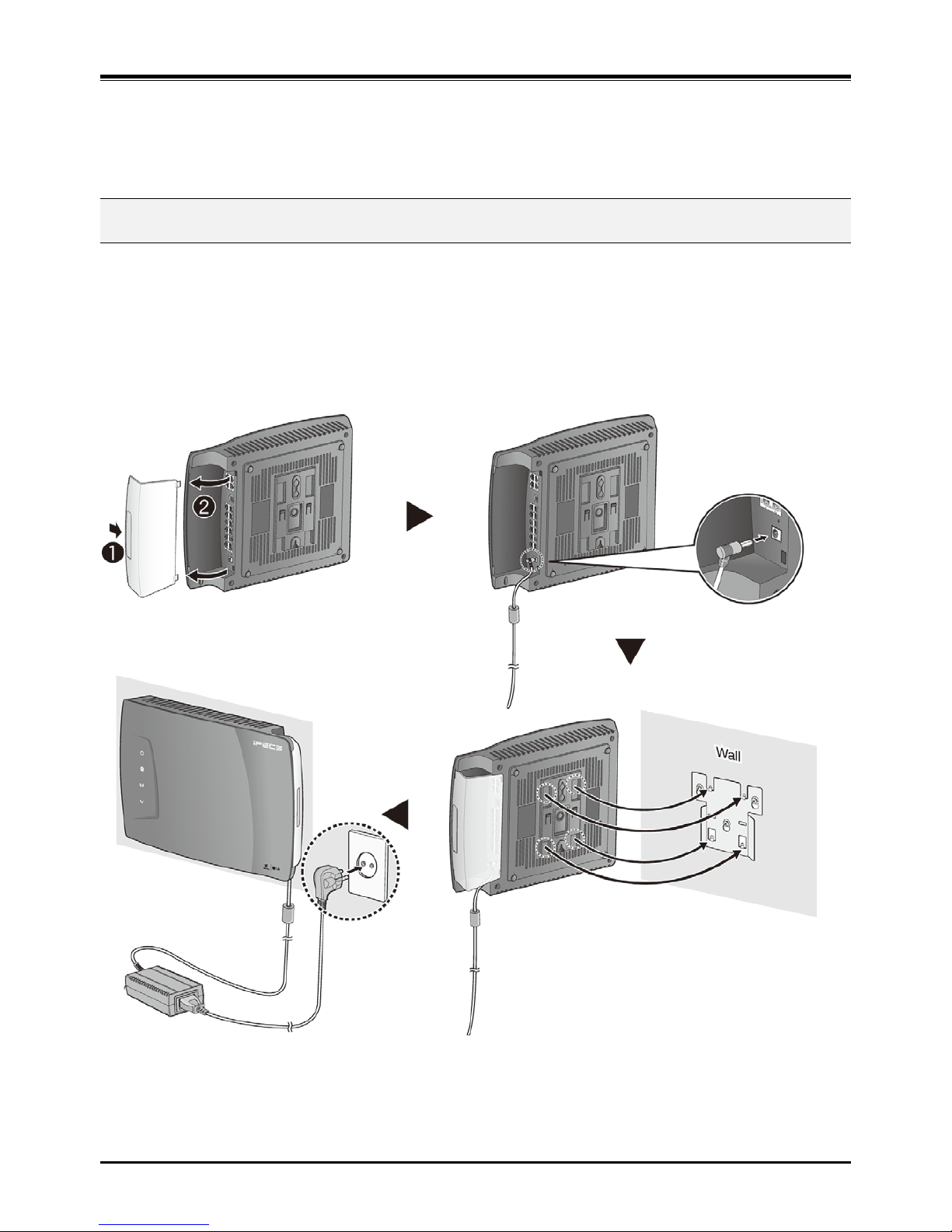
4.1.1 Connection for AC/DC adapter
1. Open the side cover.
2. Connect the plug of AC/DC adapter on the right side of the iPECS SBG-1000 system.
3. Close the side cover and insert iPECS SBG-1000 system to the wall mount bracket.
4. Connect the plug of power cord to a wall outlet.
Figure 4.1.1 Connection for AC/DC Adapter
Page 15
iPECS SBG-1000 Quick Start Guide
9
4.1.2 Connections for LAN/ WAN/ PSTN Back-up
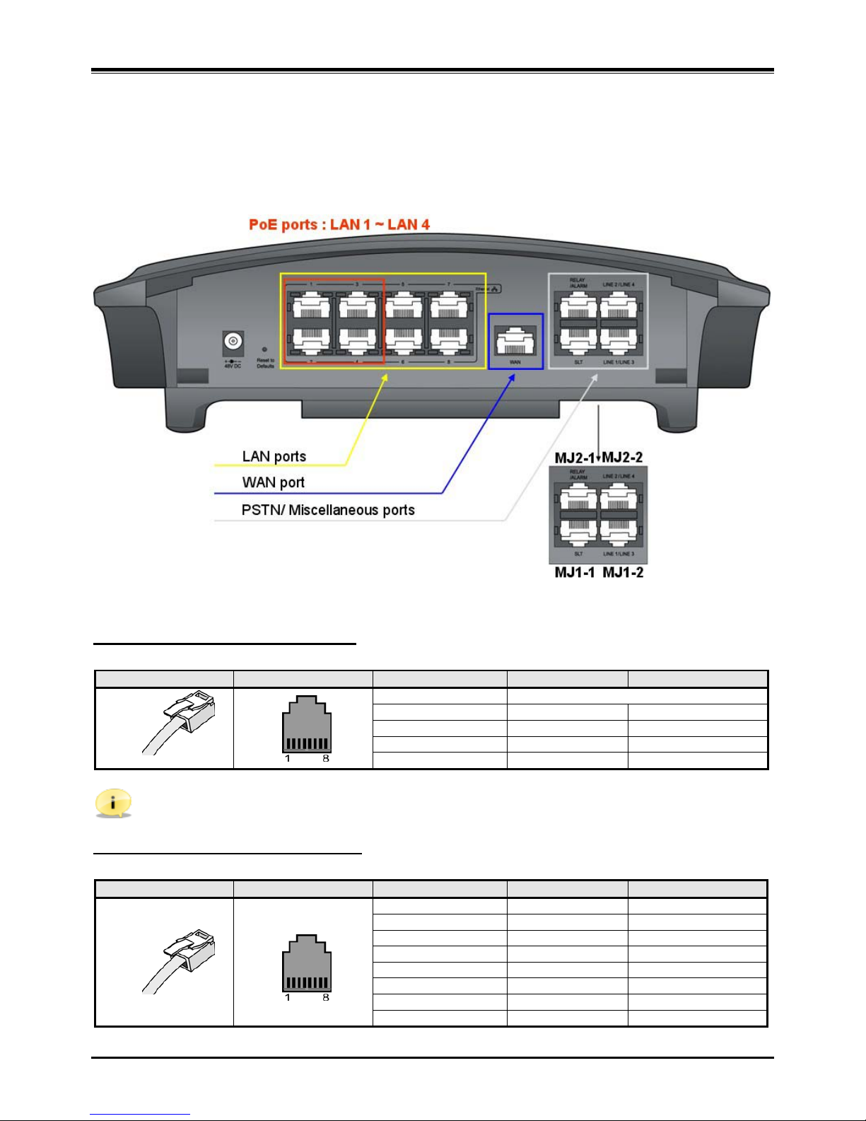
4.1.2.1 Port Definition – Right Side
The following figure shows for port connections.
Figure 4.1.2 Connections for LAN/ WAN/ PSTN Back-up
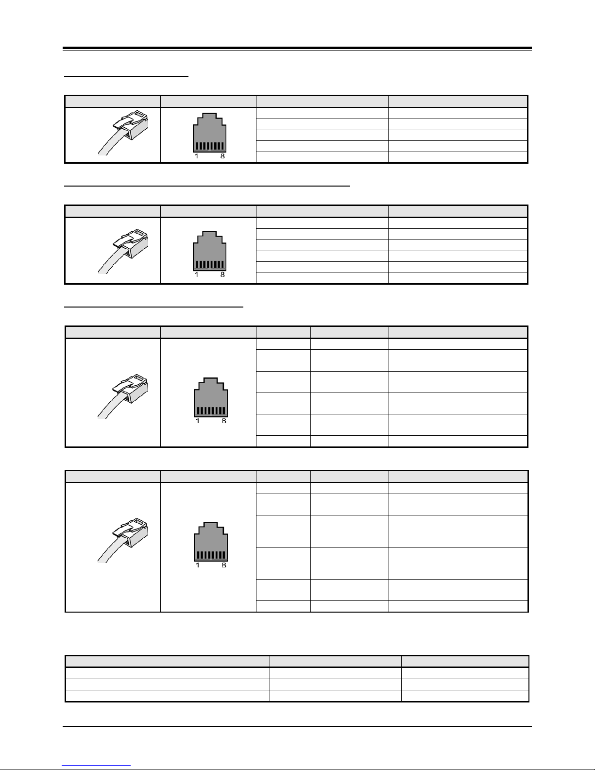
Pin Assignment for Ethernet (LAN)
LAN port
CONNECTOR
PIN NUMBER
NO.
SIGNAL NAME
FUNCTION
RJ45
4,5,7,8
Reserved
1
TX+
Transmit Data
2
TX-
Transmit Data
3
RX-
Receive Data
6
RX+
Receive Data
Note: iPECS SBG-1000 has 4 PoE ports for LAN1 ~ LAN4. (Total PoE Budgets : 20W).
Pin Assignment for Ethernet (WAN)
WAN port
CONNECTOR
PIN NUMBER
NO.
SIGNAL NAME
FUNCTION
RJ45
1
DA_P
Positive Data A
2
DA_N
Negative Data A
3
DB_P
Positive Data B
4
DC_P
Positive Data C
5
DC_N
Negative Data C
6
DB_N
Negative Data B
7
DD_P
Positive Data D
8
DD_N
Negative Data D
Page 16
iPECS SBG-1000 Quick Start Guide
10
Pin Assignment for SLT
SLT port (MJ1-1)
CONNECTOR
PIN NUMBER
NO.
SIGNAL NAME
RJ45
1
N/A
2, 3
N/A 4 Basic SLT_RING
5
Basic SLT_TIP
6, 7, and 8
N/A
Pin Assignment for Relay Contact and Alarm Detection
MISC port (MJ2-1)
CONNECTOR
PIN NUMBER
NO.
SIGNAL NAME
RJ45
1
RELAY-TIP
2
RELAY-RING
3, 4
N/A
5, 6
N/A 7 ALARM-TIP
8
ALARM-RING
Pin Assignment for PSTN Back-up
LINE 1/ LINE 3 (MJ1-2)
CONNECTOR
PIN NUMBER
NO.
SIGNAL NAME
FUNCTION
RJ45
1, 2
N/A
3 TX+/ CO3-R Transmit data for BRIU
/ CO3-RING for CIU4
4
RX+/ CO1-R
Receive data for BRIU or
/ CO1-RING for CIU/ CSIU
5 RX-/ CO1-T Receive data for BRI U or
/ CO1-TIP for CIU/ CSIU
6
TX-/ CO3-T
Transmit data for BRIU
/ CO3-TIP for CIU4
7, 8
N/A
LINE 2/ LINE 4 (MJ2-2)
CONNECTOR
PIN NUMBER
NO.
SIGNAL NAME
FUNCTION
RJ45
1, 2
N/A
3
TX+/ CO4-R
Transmit data for BRIU2
/ CO4-RING for CIU4
4
RX+/
CO2-R/ SLT2-R
Receive data for BRI U2
/CO2-RING for CIU or
SLT2_RING for CSIU
5
RX-/
CO2-T/ SLT2-T
Receive data for BRI U2
/CO2-TIP for CIU or
SLT2_TIP for CSIU
6
TX-/ CO4-T
Transmit data for BRIU2
/ CO4-TIP for CIU4
7, 8
N/A
PSTN Back-up functions can be supported with ONLY one of followin g da ugh t er bo ar d ty pes as sem bl ed fr om th e
factory.
Daughter board types for PSTN Back-up
Resources
Remark
CIU1/ CIU2/ CI U 4 installed in iPECS SB G -1000
1 or 2 or 4 CO Port
CO Interface Uni t
BRIU/ BRIU2 installed in iPECS SBG-1000
1 or 2 BRI Port (2B + D)
Basic Rate Int erface Unit
CSIU installed in iPECS SBG-1000
1 CO & 1 SLT Port
CO & SLT Interface Unit
Page 17
iPECS SBG-1000 Quick Start Guide
11
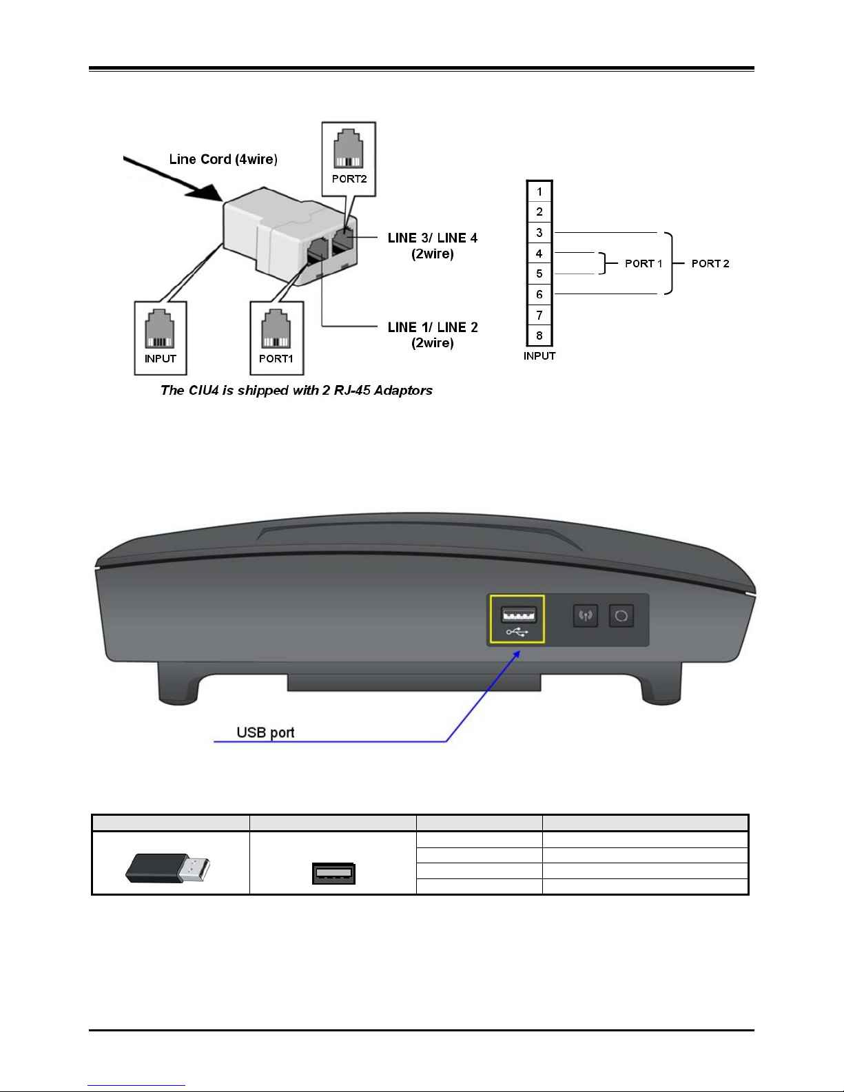
4.1.2.2 Pin Assignment for CIU4
Figure 4.1.3 Pin Assignment for CIU4
4.1.2.3 Port Definition – Left Side
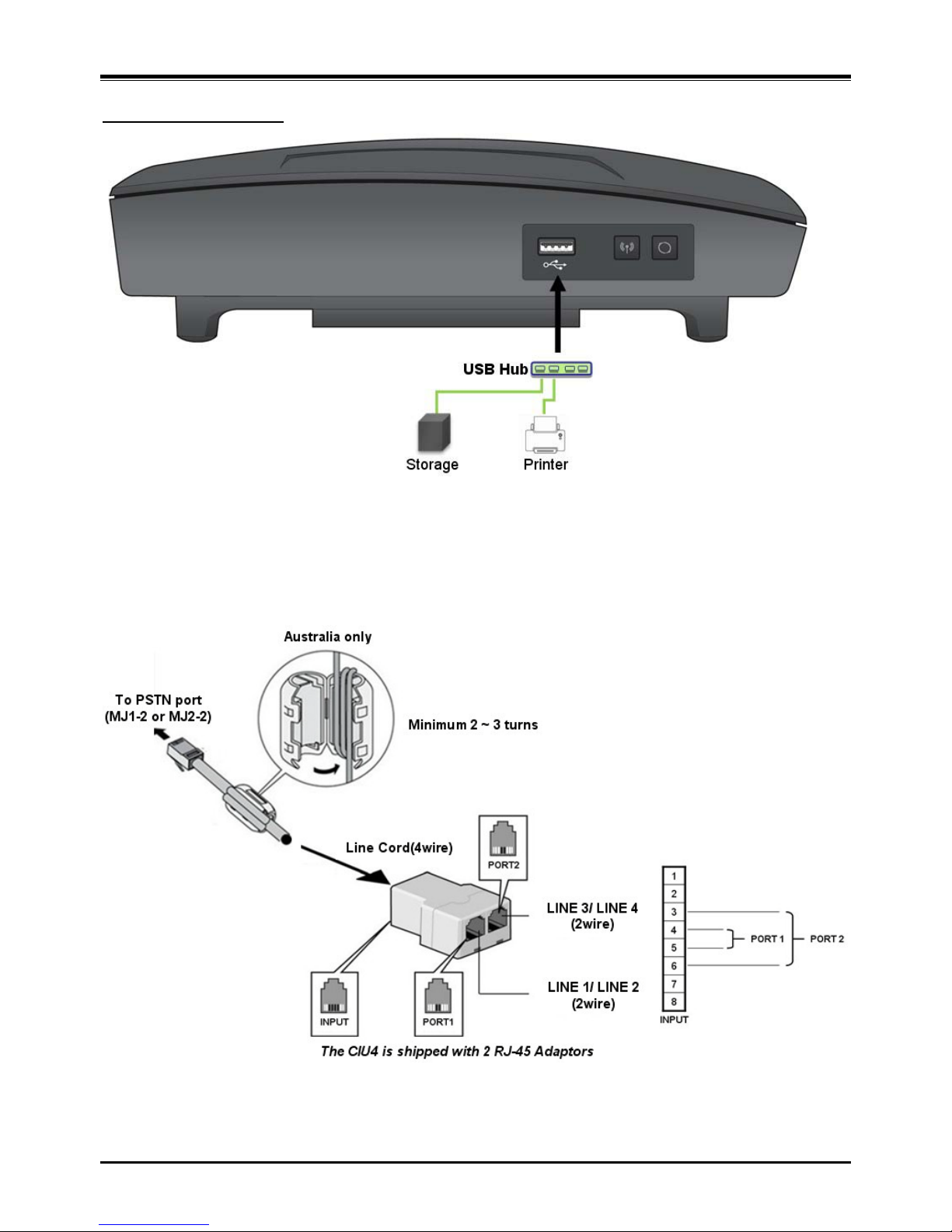
The following figure shows for USB connection.
Figure 4.1.4 Connection for USB
USB port
CONNECTOR
PIN NUMBER
NO.
SIGNAL NAME
USB Type A
1
GND
2
D+
3
D- 4 VBUS (+5V)
4 3 2 1
Page 18
iPECS SBG-1000 Quick Start Guide
12
Example for USB port
Figure 4.1.5 Example for USB port
4.1.2.4 Attaching a ferrite core (Australia only)
The following figure shows how to attach Ferrite cor es .
Figure 4.1.6 Attaching a ferrite core
Page 19
iPECS SBG-1000 Quick Start Guide
13
5 FF
UUNNCCTTIIOONN
B
B
UUTTTTOONNSS
/
/
LLEED
D
I
I
CCOONNSS
/
/
LLEED
D
S
S
5.1 Function Buttons / LED Icons / LEDs
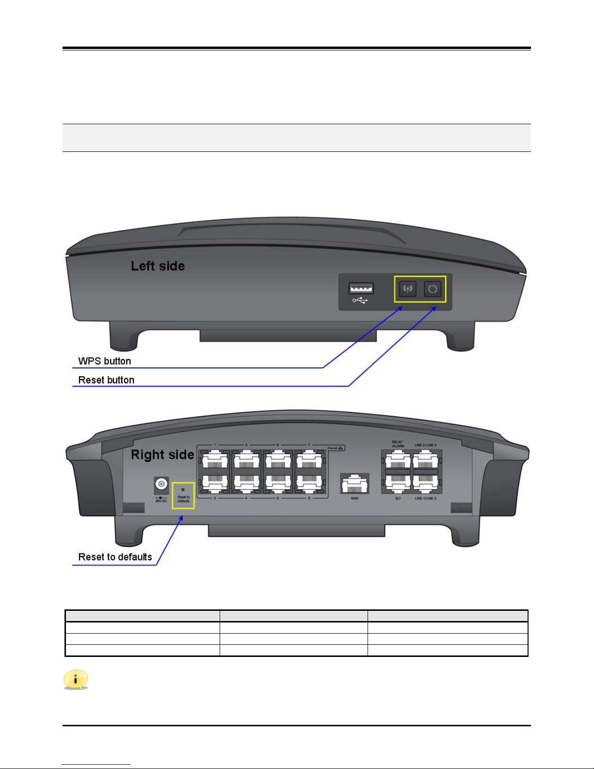
5.1.1 Function Buttons
The following figure shows for button functions.
Figure 5.1.1 Function buttons
iPECS SBG-1000 has 3 function buttons.
Buttons
Functions
Remark
WPS (WiFi Protected Setup)
Simple WiFi Configuration
Refer to CD ma nu al for more detail
Reset
System Reset
Reset to defaults
Database Clear
Refer to CD man ual for mor e de t ail
Note:
. WPS button is used to simplify t he process of configuring security on wireless networks.
. Reset to defaults button is used for clearing iPECS SBG-1000’s database only when pressed more than 5
seconds.
Page 20
iPECS SBG-1000 Quick Start Guide
14
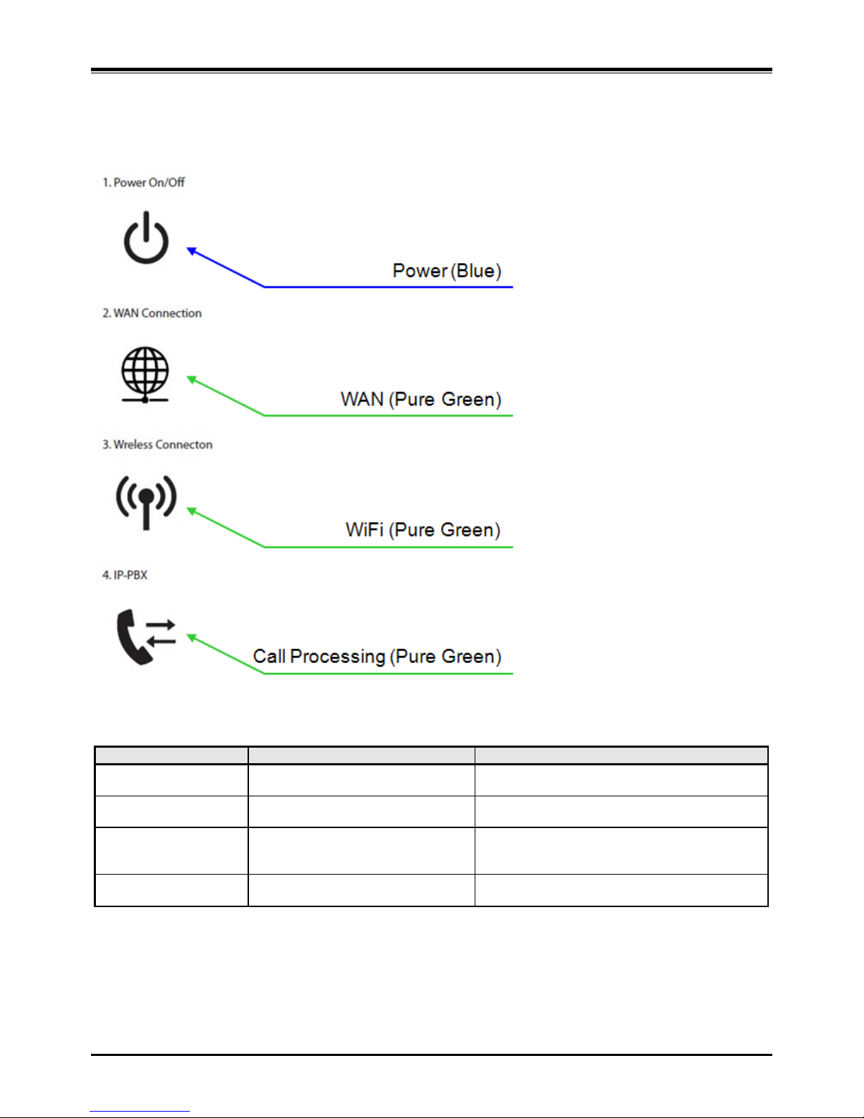
5.1.2 LED Icons
The following figure shows for the Icons on the top of iPECS SBG-1000.
Figure 5.1.2 LED Icons
Icons
Functions
Remark
Power
(Blue)
Power Connection
On – Connected
Off or Blink – Abnormal or not connected
WAN
(Pure Green)
WAN Connection
On – Connected
Off or Blink – Abnormal or not connected
WiFi
(Pure Green)
WiFi Status
On – Normal
Off – Abnormal
Blink – WPS Operation
IP-PBX
(Pure Green)
iPECS Call Processing
Blink – Normal
On or Off - Abnormal
Page 21

iPECS SBG-1000 Quick Start Guide
15
5.1.3 LEDs
The following figure shows for LED functions.
Figure 5.1.3 LEDs
5.1.3.1 LEDs for Ethernet (WAN)
LED Indication (WAN port)
LED
DESCRIPTION
Orange Color
Activity Status LED – Blink : Active, ON : Idle
Green Color
Link Status LED – ON : Link OK, OFF : No Link
5.1.3.2 LEDs for Ethernet (LAN)
LED Indication (LAN ports)
LED
DESCRIPTION
Orange Color
Speed Status LED – ON : 100Mbps, OFF : 10Mbps
Green Color
Link Status LED – ON : Link OK, OFF : No Link,
Blink : Data Trans f er
Page 22
iPECS SBG-1000 Quick Start Guide
16
6 SS
TTAARRTTIINNGG I
I
PPEECCS
S
SSBBGG--11000000
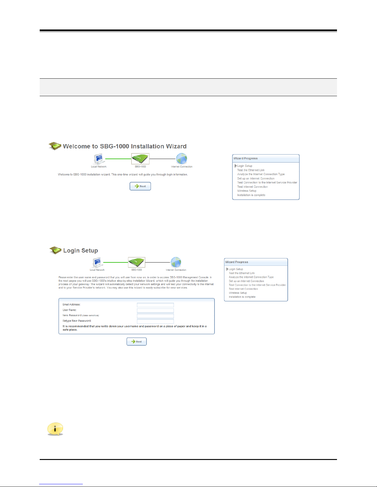
6.1 Installation Wizard
The installation wizard is the first and foremost configuration procedure, which automatically diagnoses your network
environment and configures its components. It is a step-by-step procedure that guides you through establishing an
Internet connection, a wireless network, and helps you to subscribe for different services. The wizard progress box,
located at the right hand side of the screen, provides a monitoring tool for its steps during the installation progress.
Figure 6.1 Welcome to iPECS SBG-1000 Installation Wizard
1. To start the installation wizard, perform the following: Select the desired language and click ‘Next’ to continue.
The ‘Login Setup’ screen appears.
Figure 6.2. Login Setup
2. Enter a valid email address. It will be used by your service provider for sending you important service
information.
3. The ‘User Name’ field is auto-completed by the username part of your email address. You can enter another
username, which may only consist of letters and numbers.
4. Enter a password, and retype it in the next field to verify its correctness.
Note: It is recommended to write down your login details on a piece of paper, and store it in a safe place.
5. Click ‘Next’. The wizard is now ready to begin your gateway’s configuration.
Page 23
iPECS SBG-1000 Quick Start Guide
17
6. Click ‘Next’. The wizard procedure will commence, performing the steps listed in the progress box
consecutively, stopping only if a step fails or if input is required. The following sections describe the wizard
steps along with their success/failure scenarios. If a step fails, use the ‘Retry’ or ‘Skip’ buttons to continue.
Warning: The installation wizard overrides all Internet connection settings, which you may have previously
defined.
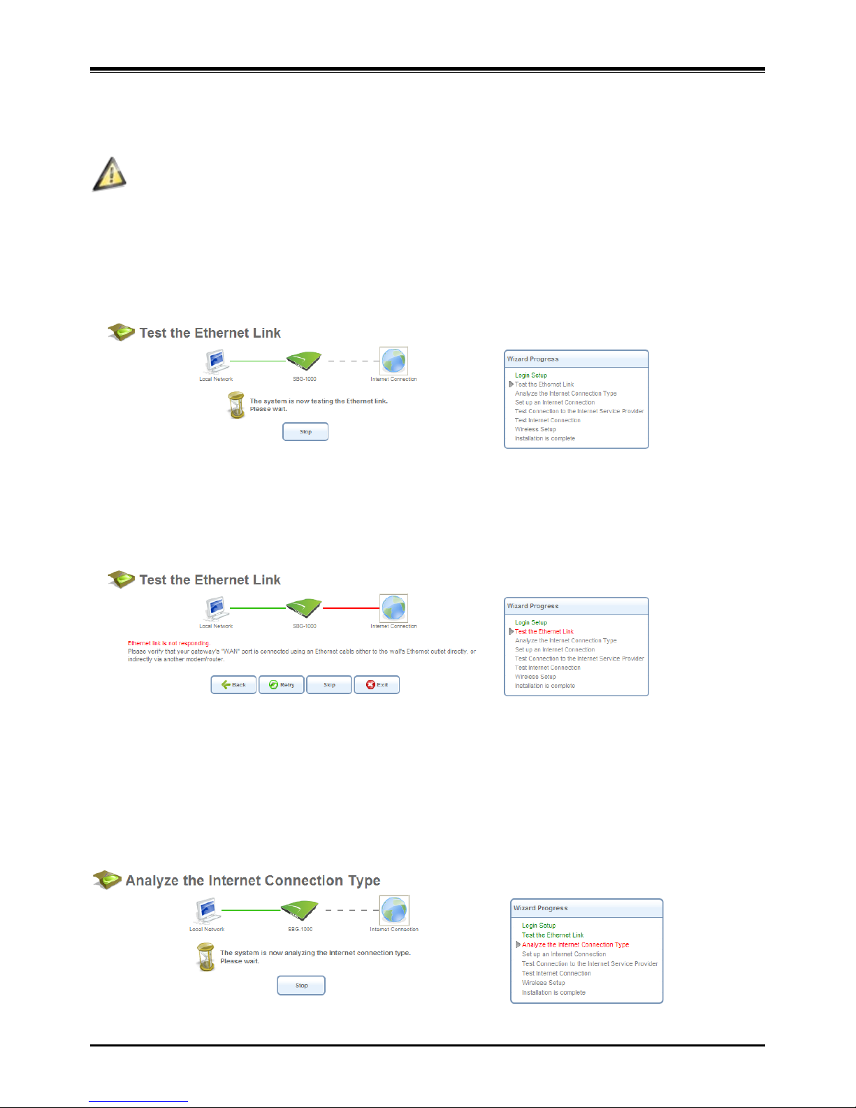
6.1.1 Step 1: Test Ethernet Link
The first step is a test of the Ethernet connection.
Figure 6.3 Test Ethernet Link
This step may fail if iPECS SBG-1000 cannot detect your Ethernet link (for example, if the cable is unplugged). In this
case, the screen changes to the following.
Figure 6.4 Test Ethernet Link – Failure
Verify that your Ethernet/DSL cable is connected properly, and click ‘Retry’.
6.1.2 Step 2: Analyze Internet Connection Type
The next step is an analysis of your Internet connection.
Figure 6.5 Analyze Internet Connection Type
Page 24
iPECS SBG-1000 Quick Start Guide
18
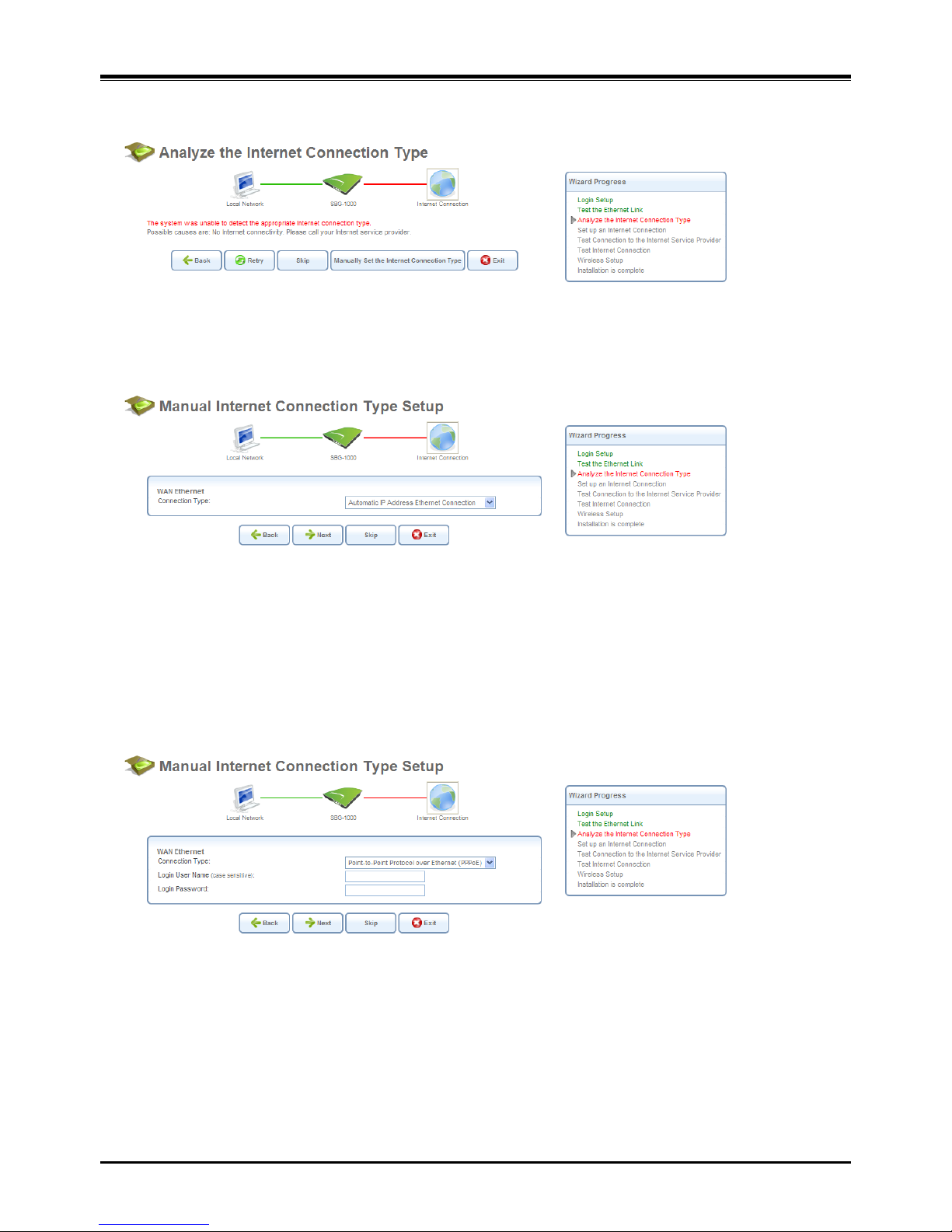
This step may fail if iPECS SBG-1000 is unable to detect your Internet connection type.
Figure 6.6 Analyze Internet Connection Type – Failure
In this case, you can manually set the Internet connection type, by clicking the corresponding button. The following
screen appears.
Figure 6.7 Manual Internet Connection Type Setup
To learn about manually configuring your Internet connection, refer to Section 6.4 in iPECS SBG-1000 User Guide.
6.1.3 Step 3: Setup Internet Connection
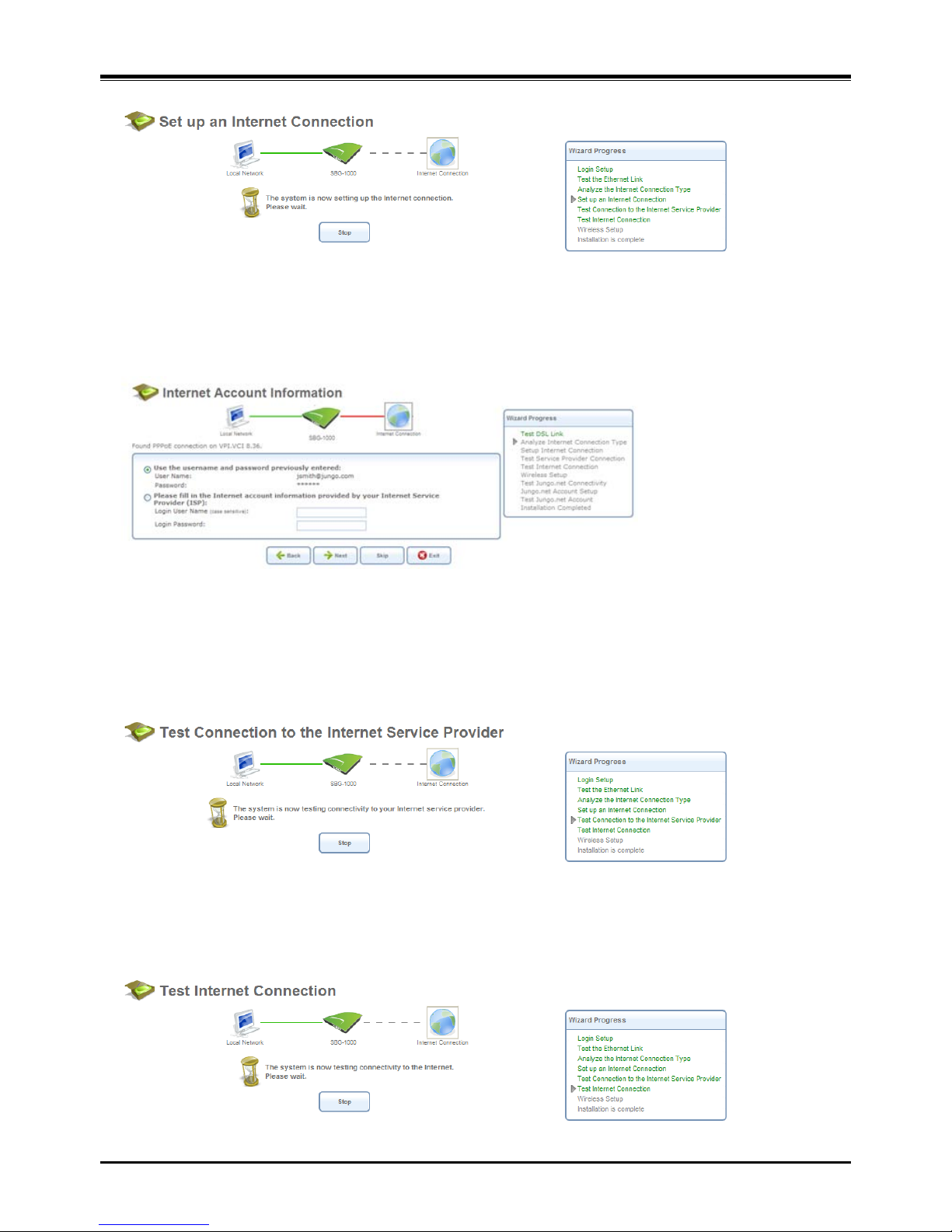
If your Internet connection requires login details provided by your Internet Service Provider (ISP) (e.g. when using
PPPoE), the following screen appears.
Figure 6.8 Internet Account Information
Enter your user name and password and click ‘Next’. Failure to enter the correct details yields the following message.
Click ‘Back’ and try again.
Page 25
iPECS SBG-1000 Quick Start Guide
19
Figure 6.9 Setup Internet Connection
You may have forgotten your login details, issued by your ISP. iPECS SBG-1000 saves the username and password
of the PPPoE connection to the ISP, even if it is restored to the factory default settings. When restoring the connection
with the installation wizard, iPECS SBG-1000 will offer your old login details.
Figure 6.10 Internet Account Information
6.1.4 Step 4: Test Service Provider Connection
This step tests the connectivity to your ISP.
Figure 6.11 Test Service Provider Connection
6.1.5 Step 5: Test Internet Connection
This step tests the connectivity to the Internet.
Figure 6.12 Test Internet Connection
Page 26
iPECS SBG-1000 Quick Start Guide
20
6.1.6 Step 6: Wireless Setup
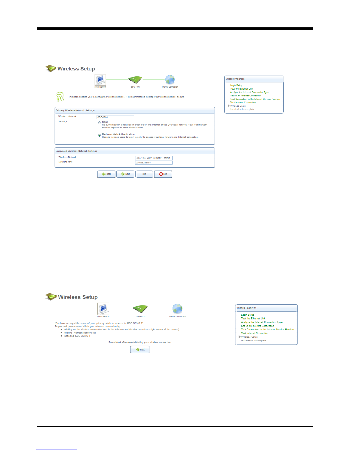
This step enables you to rename your wireless network, as well as change its security level.
Figure 6.13 Wireless Setup
iPECS SBG-1000 assigns a default name for its wireless network, which you may later change. Select the wireless
security level. The default “Medium” level secures your network by requiring users to provide a password in order to
connect. “High” level utilizes the Wi-Fi Protected Access (WPA) protocol, requiring a password (network key) as well,
but also encrypts the wireless traffic. When selecting this option, enter an eight-character password in the provided
field. Click ‘Next’ to continue.
6.1.6.1 Setup via Wireless Connection
If you are running the installation wizard while being connected to iPECS SBG-1000 via a wireless connection, the
wizard does not change the default SSID (to prevent you from disconnecting). If you choose to change it manually,
the following screen appears, requesting that you re-establish your wireless connection (from your computer) before
proceeding with the wizard.
Figure 6.14 Wireless Setup
This screen also appears after selecting the High wireless security level, or after changing the previously entered
WPA password (sees Figure 6.13).
Page 27
iPECS SBG-1000 Quick Start Guide
21
6.1.6.2 Additional SSIDs with Virtual Access Points
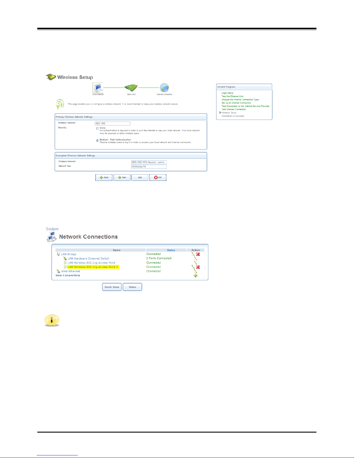
If your gateway supports multiple virtual access points, an additional pre-configured WPA-secured wireless network is
displayed in ‘Wireless Setup’ screen.
Figure 6.15 Wireless Setup
You can change the default name and network key (password) of this encrypted wireless network in their respective
text fields (clicking ‘Next’ will save the new details). This wireless network will also appear in the ‘Network
Connections’ screen under the ‘System’ tab, where it can be edited or deleted such as any other network connection.
Figure 6.16 Network Connections
Note: In order to delete this connection, you must first remove it from under the LAN bridge.
Page 28
iPECS SBG-1000 Quick Start Guide
22
6.1.7 Step 7: Installation Completed
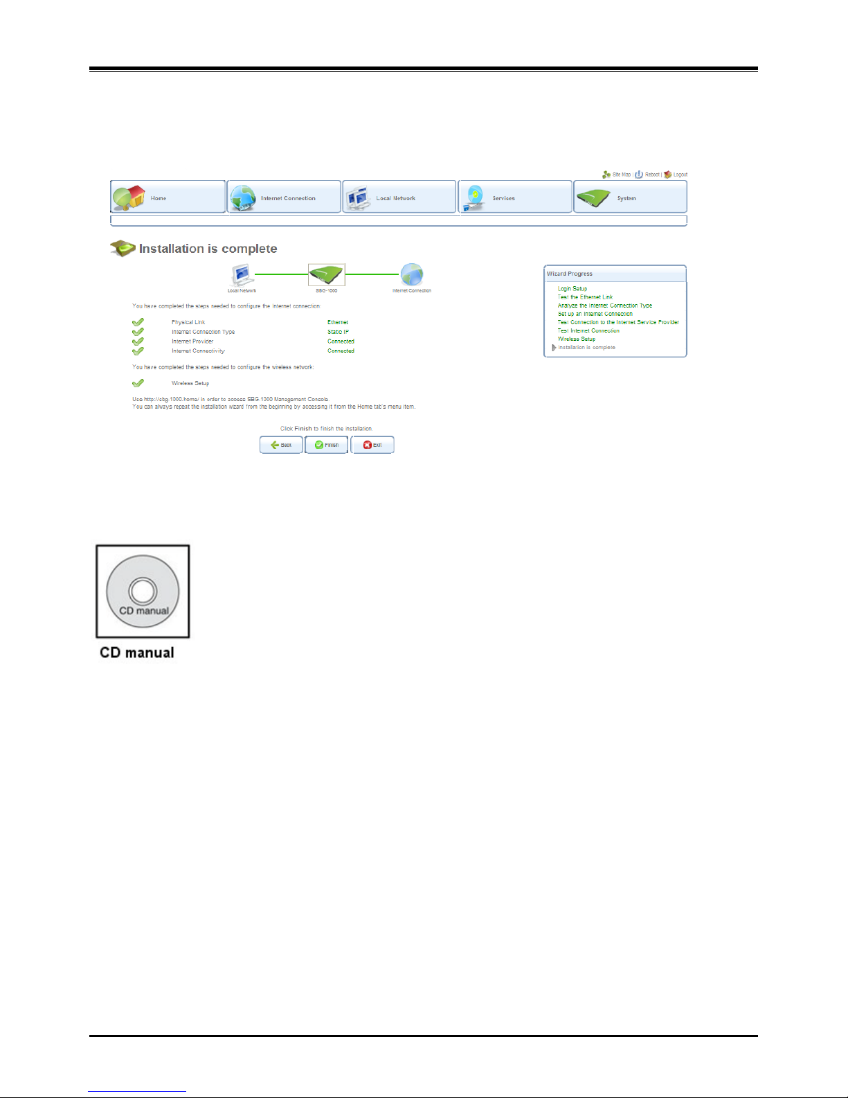
This screen provides a summary of all the above Internet connection configuration steps and their results. Click
‘Finish’ to complete the wizard procedure.
Figure 6.17 Installation Completed
Refer to CD manual for more detailed information.
Page 29

iPECS SBG-1000 Quick Start Guide
23
7 TT
RROOUUBBLLEESSHHOOOOTTIINNG
G
Problem
Cause/Symptom
Solution
System power f a i lu re
AC Power Fail
Check the AC Power s our ce.
Check the Inlet and adapter connection.
Replace AC/DC adapter with a good one.
Power On/Off Icon
(On – Normal, Off or blink – Abnormal)
Check DC Output voltage and DC/DC.
System does not operate
Power Short Circuit
(Adapter, DC/ DC ci rc uit on mai n b oar d)
Check the connection between main board
and PSTN back-up board.
Check AC/DC adapter and DC/DC.
Check a short circuit on the main board
or PSTN back-up board.
Press the Reset button for sy s tem rest ar t.
Press the Reset to defaults button for
The factory def a ul t m o d e.
Bad Board Connection
(PSTN Back-up Board)
IP phone does not
operate
Bad Connection
(Between the LAN port and IP Terminals)
Check the connection between the LAN port
and IP Terminals on MDF.
SBG has 4 PoE port s for L AN1 ~ LA N4.
The other ports (LAN5~LAN8) should be
connected adapter to IP Terminals.
Maximum Distance of LAN port
Check the Max. distance between the LAN
port and IP terminals
Bad IP Terminals
Plug the IP Terminals into another LAN port
that has been verified as working. If the IP
Terminals
still does not work properly,
replace the IP Terminals.
SLT does not operate
Bad Connection
(Between the SLT port and SLT)
Check the connection between the lines of
the SLT on the MDF.
(Refer to connections for MDF)
CO line operation failure
Bad Connection
(Between the CO port and CO line)
Check the connection between the lines of
the CO on the MDF.
(Refer to connections for MDF)
Relay does not operate
Bad Connection
Check the connection.
(Refer to connections for MDF)
Alarm does not operate
Bad Connection
Check the connection.
(Refer to connections for MDF)
WAN does not operate
Bad Connection or IP Setting
Check the network connection.
(Refer to connections for MDF)
Check WAN type and IP setting.
WAN Icon (On : connected)
Check WAN LEDs on modular jack.
LAN does not operate
Bad Connection or IP Setting
Check the network connection.
(Refer to connections for MDF)
Check LAN LEDs on modular jack.
(Link/Activity, Speed)
WiFi does not operate
Bad Connection
Check wireless network and setting.
Recommend the wall mount for WiFi.
DECT does not operate
Bad Connection
Check DECT terminal setting.
Recommend the wall mount for DECT.
 Loading...