

Page 1

iPECS is an Ericsson-LG Brand
Please read this manual carefully before
operating your set. Retain it for future reference.
ES-3052G / ES-3052GP
User Manual
U
SER
G
UIDE
Page 2
U
ES-3052 Series
SER
M
ANUAL
ES-3052G MANAGED 52-PORT GE SWITCH
Layer 2 Managed Switch
with 48 10/100/1000BASE-T (RJ-45) Ports,
and 4 Gigabit SFP Ports
ES-3052GP MANAGED 52-PORT GE POE SWITCH
Layer 2 Managed Switch
with 48 10/100/1000BASE-T (RJ-45) PoE Ports,
and 4 Gigabit SFP Ports
ES-3052G
ES-3052GP
E042013/ST-R01
149100000226A
Page 3
ES-3052 Series
ABOUT THIS GUIDE
PURPOSE This guide gives specific information on how to operate and use the
management functions of the switch.
AUDIENCE The guide is intended for use by network administrators who are
responsible for operating and maintaining network equipment;
consequently, it assumes a basic working knowledge of general switch
functions, the Internet Protocol (IP), and Simple Network Management
Protocol (SNMP).
CONVENTIONS The following conventions are used throughout this guide to show
information:
N
OTE
:
Emphasizes important information or calls your attention to related
features or instructions.
C
AUTION
damage the system or equipment.
W
ARNING
:
Alerts you to a potential hazard that could cause loss of data, or
:
Alerts you to a potential hazard that could cause personal injury.
NOTICE OF CHANGES Ericsson-LG reserves the right to change specifications at any time without
notice.
RELATED PUBLICATIONS The following publication details the hardware features of the switch,
including the physical and performance-related characteristics, and how to
install the switch:
The Installation Guide
Also, as part of the switch’s software, there is an online web-based help
that describes all management related features.
– 3 –
Page 4

A
ES-3052 Series
BOUT THIS GUIDE
REVISION HISTORY This section summarizes the changes in each revision of this guide.
APRIL 2013 REVISION
This is the first version of this guide. This guide is valid for software release
v1.2.16.0.
– 4 –
Page 5

ES-3052 Series
CONTENTS
ABOUT THIS GUIDE 3
ONTENTS 5
C
IGURES 31
F
ABLES 41
T
SECTION I GETTING STARTED 47
1INTRODUCTION 49
Key Features 49
Description of Software Features 50
System Defaults 54
2INITIAL SWITCH CONFIGURATION 57
Connecting to the Switch 57
Configuration Options 57
Required Connections 58
Remote Connections 59
Basic Configuration 60
Console Connection 60
Setting Passwords 60
Setting an IP Address 61
Downloading a Configuration File Referenced by a DHCP Server 67
Enabling SNMP Management Access 69
Managing System Files 71
Saving or Restoring Configuration Settings 72
SECTION II WEB CONFIGURATION 75
3USING THE WEB INTERFACE 77
Connecting to the Web Interface 77
– 5 –
Page 6

C
ES-3052 Series
ONTENTS
Navigating the Web Browser Interface 78
Home Page 78
Configuration Options 79
Panel Display 79
Showing Status Information 80
Main Menu 81
4BASIC MANAGEMENT TASKS 95
Displaying System Information 95
Displaying Switch Hardware/Software Versions 97
Configuring Support for Jumbo Frames 98
Displaying Bridge Extension Capabilities 99
Managing System Files 101
Copying Files via FTP/TFTP or HTTP 101
Saving the Running Configuration to a Local File 103
Setting The Start-Up File 104
Showing System Files 104
Automatic Operation Code Upgrade 105
Setting the System Clock 110
Setting the Time Manually 110
Setting the SNTP Polling Interval 111
Specifying SNTP Time Servers 112
Setting the Time Zone 113
Configuring Summer Time 114
Configuring the Console Port 116
Configuring Telnet Settings 118
Displaying CPU Utilization 120
Displaying Memory Utilization 121
Resetting the System 121
5INTERFACE CONFIGURATION 127
Port Configuration 127
Configuring by Port List 127
Configuring by Port Range 130
Displaying Connection Status 131
Configuring Local Port Mirroring 132
Configuring Remote Port Mirroring 134
Showing Port or Trunk Statistics 138
– 6 –
Page 7

C
ES-3052 Series
ONTENTS
Performing Cable Diagnostics 142
Trunk Configuration 144
Configuring a Static Trunk 145
Configuring a Dynamic Trunk 148
Displaying LACP Port Counters 153
Displaying LACP Settings and Status for the Local Side 154
Displaying LACP Settings and Status for the Remote Side 156
Configuring Trunk Mirroring 158
Saving Power 160
Traffic Segmentation 162
Enabling Traffic Segmentation 162
Configuring Uplink and Downlink Ports 163
VLAN Trunking 164
6 VLAN CONFIGURATION 167
IEEE 802.1Q VLANs 167
Configuring VLAN Groups 170
Adding Static Members to VLANs 171
Configuring Dynamic VLAN Registration 176
IEEE 802.1Q Tunneling 180
Enabling QinQ Tunneling on the Switch 184
Adding an Interface to a QinQ Tunnel 185
Protocol VLANs 187
Configuring Protocol VLAN Groups 187
Mapping Protocol Groups to Interfaces 189
Configuring IP Subnet VLANs 191
Configuring MAC-based VLANs 193
Configuring VLAN Mirroring 195
7ADDRESS TABLE SETTINGS 197
Setting Static Addresses 197
Changing the Aging Time 199
Displaying the Dynamic Address Table 200
Clearing the Dynamic Address Table 201
Configuring MAC Address Mirroring 202
8SPANNING TREE ALGORITHM 205
Overview 205
Configuring Loopback Detection 208
– 7 –
Page 8

C
ES-3052 Series
ONTENTS
Configuring Global Settings for STA 209
Displaying Global Settings for STA 215
Configuring Interface Settings for STA 216
Displaying Interface Settings for STA 220
Configuring Multiple Spanning Trees 222
Configuring Interface Settings for MSTP 226
9CONGESTION CONTROL 229
Rate Limiting 229
Storm Control 231
Automatic Traffic Control 234
Setting the ATC Timers 235
Configuring ATC Thresholds and Responses 237
10 CLASS OF SERVICE 241
Layer 2 Queue Settings 241
Setting the Default Priority for Interfaces 241
Selecting the Queue Mode 242
Mapping CoS Values to Egress Queues 245
Layer 3/4 Priority Settings 248
Setting Priority Processing to DSCP or CoS 248
Mapping Ingress DSCP Values to Internal DSCP Values 249
Mapping CoS Priorities to Internal DSCP Values 252
11 QUALITY OF SERVICE 255
Overview 255
Configuring a Class Map 256
Creating QoS Policies 259
Attaching a Policy Map to a Port 269
12 VOIP TRAFFIC CONFIGURATION 271
Overview 271
Configuring VoIP Traffic 272
Configuring Telephony OUI 273
Configuring VoIP Traffic Ports 275
13 SECURITY MEASURES 279
AAA Authorization and Accounting 280
Configuring Local/Remote Logon Authentication 281
Configuring Remote Logon Authentication Servers 282
Configuring AAA Accounting 287
– 8 –
Page 9

C
ES-3052 Series
ONTENTS
Configuring AAA Authorization 292
Configuring User Accounts 296
Web Authentication 298
Configuring Global Settings for Web Authentication 298
Configuring Interface Settings for Web Authentication 299
Network Access (MAC Address Authentication) 300
Configuring Global Settings for Network Access 303
Configuring Network Access for Ports 304
Configuring Port Link Detection 306
Configuring a MAC Address Filter 307
Displaying Secure MAC Address Information 309
Configuring HTTPS 311
Configuring Global Settings for HTTPS 311
Replacing the Default Secure-site Certificate 312
Configuring the Secure Shell 314
Configuring the SSH Server 317
Generating the Host Key Pair 318
Importing User Public Keys 320
Access Control Lists 322
Showing TCAM Utilization 323
Setting the ACL Name and Type 324
Configuring a Standard IPv4 ACL 326
Configuring an Extended IPv4 ACL 327
Configuring a Standard IPv6 ACL 331
Configuring an Extended IPv6 ACL 333
Configuring a MAC ACL 335
Configuring an ARP ACL 337
Binding a Port to an Access Control List 339
ARP Inspection 340
Configuring Global Settings for ARP Inspection 341
Configuring VLAN Settings for ARP Inspection 343
Configuring Interface Settings for ARP Inspection 345
Displaying ARP Inspection Statistics 346
Displaying the ARP Inspection Log 348
Filtering IP Addresses for Management Access 349
Configuring Port Security 351
– 9 –
Page 10

C
ES-3052 Series
ONTENTS
Configuring 802.1X Port Authentication 353
Configuring 802.1X Global Settings 355
Configuring Port Authenticator Settings for 802.1X 356
Configuring Port Supplicant Settings for 802.1X 361
Displaying 802.1X Statistics 363
IP Source Guard 365
Configuring Ports for IP Source Guard 365
Configuring Static Bindings for IP Source Guard 367
Displaying Information for Dynamic IP Source Guard Bindings 369
DHCP Snooping 370
DHCP Snooping Configuration 373
DHCP Snooping VLAN Configuration 374
Configuring Ports for DHCP Snooping 375
Displaying DHCP Snooping Binding Information 376
DoS Protection 377
14 BASIC ADMINISTRATION PROTOCOLS 379
Configuring Event Logging 379
System Log Configuration 379
Remote Log Configuration 382
Sending Simple Mail Transfer Protocol Alerts 383
Link Layer Discovery Protocol 387
Setting LLDP Timing Attributes 387
Configuring LLDP Interface Attributes 389
Configuring LLDP Interface Civic-Address 393
Displaying LLDP Local Device Information 396
Displaying LLDP Remote Port Information 399
Displaying Device Statistics 404
Power Over Ethernet 406
Displaying the Switch’s Overall PoE Power Budget 407
Setting The Port PoE Power Budget 408
Simple Network Management Protocol 410
Configuring Global Settings for SNMP 412
Setting the Local Engine ID 413
Specifying a Remote Engine ID 414
Setting SNMPv3 Views 416
Configuring SNMPv3 Groups 419
– 10 –
Page 11

C
ES-3052 Series
ONTENTS
Setting Community Access Strings 423
Configuring Local SNMPv3 Users 424
Configuring Remote SNMPv3 Users 426
Specifying Notification Managers 429
Remote Monitoring 434
Configuring RMON Alarms 434
Configuring RMON Events 437
Configuring RMON History Samples 440
Configuring RMON Statistical Samples 443
Switch Clustering 446
Configuring General Settings for Clusters 447
Cluster Member Configuration 448
Managing Cluster Members 450
Setting A Time Range 451
15 IP CONFIGURATION 455
Using the Ping Function 455
Address Resolution Protocol 457
Setting the ARP Timeout 457
Displaying ARP Entries 458
Setting the Switch’s IP Address (IP Version 4) 459
Setting the Switch’s IP Address (IP Version 6) 462
Configuring the IPv6 Default Gateway 462
Configuring IPv6 Interface Settings 463
Configuring an IPv6 Address 465
Showing IPv6 Addresses 467
Showing the IPv6 Neighbor Cache 469
Showing IPv6 Statistics 471
16 IP SERVICES 477
Configuring General DNS Service Parameters 477
Configuring a List of Domain Names 478
Configuring a List of Name Servers 480
Configuring Static DNS Host to Address Entries 481
Displaying the DNS Cache 483
17 MULTICAST FILTERING 485
Overview 485
– 11 –
Page 12

C
ES-3052 Series
ONTENTS
Layer 2 IGMP (Snooping and Query) 486
Configuring IGMP Snooping and Query Parameters 488
Specifying Static Interfaces for a Multicast Router 491
Assigning Interfaces to Multicast Services 493
Setting IGMP Snooping Status per Interface 496
Displaying Multicast Groups Discovered by IGMP Snooping 501
Filtering and Throttling IGMP Groups 502
Enabling IGMP Filtering and Throttling 502
Configuring IGMP Filter Profiles 503
Configuring IGMP Filtering and Throttling for Interfaces 506
Multicast VLAN Registration 507
Configuring Global MVR Settings 509
Configuring MVR Interface Status 510
Assigning Static Multicast Groups to Interfaces 512
Showing Multicast Group Members 514
SECTION III COMMAND LINE INTERFACE 515
18 USING THE COMMAND LINE INTERFACE 517
Accessing the CLI 517
Console Connection 517
Telnet Connection 518
Entering Commands 519
Keywords and Arguments 519
Minimum Abbreviation 519
Command Completion 519
Getting Help on Commands 520
Partial Keyword Lookup 521
Negating the Effect of Commands 521
Using Command History 521
Understanding Command Modes 522
Exec Commands 522
Configuration Commands 523
Command Line Processing 524
Showing Status Information 525
Output Modifiers 526
– 12 –
Page 13

C
ES-3052 Series
ONTENTS
CLI Command Groups 526
19 GENERAL COMMANDS 529
prompt 529
reload (Global Configuration) 530
enable 531
quit 532
show history 532
configure 533
disable 534
reload (Privileged Exec) 534
show reload 535
end 535
exit 535
20 SYSTEM MANAGEMENT COMMANDS 537
Device Designation 537
hostname 538
System Status 538
show access-list tcam-utilization 539
show memory 539
show process cpu 540
show running-config 540
show startup-config 541
show system 542
show tech-support 543
show users 543
show version 544
Frame Size 545
jumbo frame 545
File Management 546
boot system 547
copy 548
delete 551
dir 551
whichboot 552
upgrade opcode auto 553
upgrade opcode path 554
– 13 –
Page 14

C
ES-3052 Series
ONTENTS
Line 556
line 556
databits 557
exec-timeout 558
login 558
parity 559
password 560
password-thresh 561
silent-time 562
speed 562
stopbits 563
timeout login response 564
disconnect 564
show line 565
Event Logging 566
logging facility 566
logging history 567
logging host 568
logging on 568
logging trap 569
clear log 569
show log 570
show logging 571
SMTP Alerts 572
logging sendmail 573
logging sendmail host 573
logging sendmail level 574
logging sendmail destination-email 574
logging sendmail source-email 575
show logging sendmail 576
Time 576
sntp client 577
sntp poll 578
sntp server 578
show sntp 579
clock summer-time 579
– 14 –
Page 15

C
ES-3052 Series
ONTENTS
clock timezone 581
clock timezone-predefined 581
calendar set 582
show calendar 583
Time Range 583
time-range 583
absolute 584
periodic 585
show time-range 586
Switch Clustering 586
cluster 588
cluster commander 588
cluster ip-pool 589
cluster member 590
rcommand 590
show cluster 591
show cluster members 591
show cluster candidates 592
21 SNMP COMMANDS 593
snmp-server 594
snmp-server community 595
snmp-server contact 595
snmp-server location 596
show snmp 596
snmp-server enable traps 597
snmp-server host 598
snmp-server engine-id 601
snmp-server group 602
snmp-server user 603
snmp-server view 604
show snmp engine-id 605
show snmp group 606
show snmp user 607
show snmp view 608
nlm 608
snmp-server notify-filter 609
– 15 –
Page 16

C
ES-3052 Series
ONTENTS
show nlm oper-status 610
show snmp notify-filter 611
22 REMOTE MONITORING COMMANDS 613
rmon alarm 614
rmon event 615
rmon collection history 616
rmon collection rmon1 617
show rmon alarms 618
show rmon events 618
show rmon history 618
show rmon statistics 619
23 AUTHENTICATION COMMANDS 621
User Accounts 621
enable password 622
username 623
Authentication Sequence 624
authentication enable 624
authentication login 625
RADIUS Client 626
radius-server acct-port 626
radius-server auth-port 627
radius-server host 627
radius-server key 628
radius-server retransmit 628
radius-server timeout 629
show radius-server 629
TACACS+ Client 630
tacacs-server host 630
tacacs-server key 631
tacacs-server port 632
show tacacs-server 632
AAA 633
aaa accounting commands 633
aaa accounting dot1x 634
aaa accounting exec 635
aaa accounting update 636
– 16 –
Page 17

C
ES-3052 Series
ONTENTS
aaa authorization exec 637
aaa group server 638
server 638
accounting dot1x 639
accounting exec 639
authorization exec 640
show accounting 640
Web Server 641
ip http port 642
ip http server 642
ip http secure-server 643
ip http secure-port 644
Telnet Server 645
ip telnet max-sessions 645
ip telnet port 646
ip telnet server 646
show ip telnet 647
Secure Shell 647
ip ssh authentication-retries 650
ip ssh server 650
ip ssh server-key size 651
ip ssh timeout 652
delete public-key 652
ip ssh crypto host-key generate 653
ip ssh crypto zeroize 654
ip ssh save host-key 654
show ip ssh 655
show public-key 655
show ssh 656
802.1X Port Authentication 657
dot1x default 658
dot1x eapol-pass-through 658
dot1x system-auth-control 659
dot1x intrusion-action 659
dot1x max-req 660
dot1x operation-mode 660
– 17 –
Page 18

C
ES-3052 Series
ONTENTS
dot1x port-control 661
dot1x re-authentication 662
dot1x timeout quiet-period 662
dot1x timeout re-authperiod 663
dot1x timeout supp-timeout 663
dot1x timeout tx-period 664
dot1x re-authenticate 664
dot1x identity profile 665
dot1x max-start 666
dot1x pae supplicant 666
dot1x timeout auth-period 667
dot1x timeout held-period 667
dot1x timeout start-period 668
show dot1x 668
Management IP Filter 671
management 671
show management 672
24 GENERAL SECURITY MEASURES 675
Port Security 676
port security 676
Network Access (MAC Address Authentication) 678
network-access aging 679
network-access mac-filter 679
mac-authentication reauth-time 680
network-access dynamic-qos 681
network-access dynamic-vlan 682
network-access guest-vlan 683
network-access link-detection 683
network-access link-detection link-down 684
network-access link-detection link-up 684
network-access link-detection link-up-down 685
network-access max-mac-count 685
network-access mode mac-authentication 686
network-access port-mac-filter 687
mac-authentication intrusion-action 688
mac-authentication max-mac-count 688
– 18 –
Page 19

C
ES-3052 Series
ONTENTS
clear network-access 689
show network-access 689
show network-access mac-address-table 690
show network-access mac-filter 691
Web Authentication 691
web-auth login-attempts 692
web-auth quiet-period 693
web-auth session-timeout 693
web-auth system-auth-control 694
web-auth 694
web-auth re-authenticate (Port) 695
web-auth re-authenticate (IP) 695
show web-auth 696
show web-auth interface 696
show web-auth summary 697
DHCP Snooping 697
ip dhcp snooping 698
ip dhcp snooping database flash 700
ip dhcp snooping information option 700
ip dhcp snooping information policy 701
ip dhcp snooping verify mac-address 702
ip dhcp snooping vlan 702
ip dhcp snooping trust 703
clear ip dhcp snooping database flash 704
show ip dhcp snooping 705
show ip dhcp snooping binding 705
IP Source Guard 706
ip source-guard binding 706
ip source-guard 708
ip source-guard max-binding 709
show ip source-guard 710
show ip source-guard binding 710
ARP Inspection 711
ip arp inspection 712
ip arp inspection filter 713
ip arp inspection log-buffer logs 714
– 19 –
Page 20

C
ES-3052 Series
ONTENTS
ip arp inspection validate 715
ip arp inspection vlan 715
ip arp inspection limit 716
ip arp inspection trust 717
show ip arp inspection configuration 718
show ip arp inspection interface 718
show ip arp inspection log 719
show ip arp inspection statistics 719
show ip arp inspection vlan 719
Denial of Service Protection 720
flow tcp-udp-port-zero 720
25 ACCESS CONTROL LISTS 723
IPv4 ACLs 723
access-list ip 724
permit, deny, redirect-to (Standard IP ACL) 725
permit, deny, redirect-to (Extended IPv4 ACL) 726
ip access-group 729
show ip access-group 729
show ip access-list 730
IPv6 ACLs 731
access-list ipv6 731
permit, deny, redirect-to (Standard IPv6 ACL) 732
permit, deny, redirect-to (Extended IPv6 ACL) 733
show ipv6 access-list 735
ipv6 access-group 735
show ipv6 access-group 736
MAC ACLs 737
access-list mac 737
permit, deny, redirect-to
(MAC ACL) 738
mac access-group 740
show mac access-group 741
show mac access-list 741
ARP ACLs 742
access-list arp 742
permit, deny (ARP ACL) 743
show arp access-list 744
– 20 –
Page 21

C
ES-3052 Series
ONTENTS
ACL Information 745
show access-group 745
show access-list 745
26 INTERFACE COMMANDS 747
interface 748
alias 749
capabilities 749
description 750
flowcontrol 751
giga-phy-mode 752
negotiation 753
shutdown 754
speed-duplex 754
switchport packet-rate 755
clear counters 757
show interfaces counters 757
show interfaces status 759
show interfaces switchport 760
show interfaces transceiver 761
test cable-diagnostics 763
show cable-diagnostics 764
power-save 764
show power-save 765
27 LINK AGGREGATION COMMANDS 767
channel-group 768
lacp 769
lacp admin-key (Ethernet Interface) 770
lacp port-priority 771
lacp system-priority 772
lacp admin-key (Port Channel) 772
show lacp 773
28 POWER OVER ETHERNET COMMANDS 777
power inline compatible 777
power inline 778
power inline maximum allocation 779
power inline priority 780
– 21 –
Page 22

C
ES-3052 Series
ONTENTS
power inline time-range 781
show power inline status 781
show power inline time-range 782
show power poe 783
29 PORT MIRRORING COMMANDS 785
Local Port Mirroring Commands 785
port monitor 785
show port monitor 787
RSPAN Mirroring Commands 787
rspan source 789
rspan destination 790
rspan remote vlan 791
no rspan session 792
show rspan 793
30 RATE LIMIT COMMANDS 795
rate-limit 795
31 AUTOMATIC TRAFFIC CONTROL COMMANDS 797
auto-traffic-control apply-timer 798
auto-traffic-control release-timer 799
auto-traffic-control 800
auto-traffic-control action 800
auto-traffic-control alarm-clear-threshold 801
auto-traffic-control alarm-fire-threshold 802
auto-traffic-control auto-control-release 803
auto-traffic-control control-release 804
snmp-server enable port-traps atc broadcast-alarm-clear 804
snmp-server enable port-traps atc broadcast-alarm-fire 805
snmp-server enable port-traps atc broadcast-control-apply 805
snmp-server enable port-traps atc broadcast-control-release 806
snmp-server enable port-traps atc multicast-alarm-clear 806
snmp-server enable port-traps atc multicast-alarm-fire 807
snmp-server enable port-traps atc multicast-control-apply 807
snmp-server enable port-traps atc multicast-control-release 808
show auto-traffic-control 808
show auto-traffic-control interface 809
– 22 –
Page 23

C
ES-3052 Series
ONTENTS
32 ADDRESS TABLE COMMANDS 811
mac-address-table aging-time 811
mac-address-table static 812
clear mac-address-table dynamic 813
show mac-address-table 813
show mac-address-table aging-time 814
show mac-address-table count 815
33 SPANNING TREE COMMANDS 817
spanning-tree 818
spanning-tree cisco-prestandard 819
spanning-tree forward-time 819
spanning-tree hello-time 820
spanning-tree max-age 820
spanning-tree mode 821
spanning-tree pathcost method 822
spanning-tree priority 823
spanning-tree mst configuration 824
spanning-tree transmission-limit 824
max-hops 825
mst priority 825
mst vlan 826
name 827
revision 827
spanning-tree bpdu-filter 828
spanning-tree bpdu-guard 829
spanning-tree cost 830
spanning-tree edge-port 831
spanning-tree link-type 832
spanning-tree loopback-detection 832
spanning-tree loopback-detection release-mode 833
spanning-tree loopback-detection trap 834
spanning-tree mst cost 834
spanning-tree mst port-priority 835
spanning-tree port-priority 836
spanning-tree root-guard 837
spanning-tree spanning-disabled 837
– 23 –
Page 24

C
ES-3052 Series
ONTENTS
spanning-tree loopback-detection release 838
spanning-tree protocol-migration 839
show spanning-tree 839
show spanning-tree mst configuration 841
34 VLAN COMMANDS 843
GVRP and Bridge Extension Commands 844
bridge-ext gvrp 844
garp timer 845
switchport forbidden vlan 846
switchport gvrp 846
show bridge-ext 847
show garp timer 847
show gvrp configuration 848
Editing VLAN Groups 849
vlan database 849
vlan 850
Configuring VLAN Interfaces 851
interface vlan 851
switchport acceptable-frame-types 852
switchport allowed vlan 853
switchport ingress-filtering 854
switchport mode 854
switchport native vlan 855
vlan-trunking 856
Displaying VLAN Information 857
show vlan 857
Configuring IEEE 802.1Q Tunneling 858
dot1q-tunnel system-tunnel-control 859
switchport dot1q-tunnel mode 860
switchport dot1q-tunnel tpid 861
show dot1q-tunnel 862
Configuring Port-based Traffic Segmentation 862
traffic-segmentation 862
show traffic-segmentation 863
Configuring Protocol-based VLANs 864
protocol-vlan protocol-group (Configuring Groups) 865
– 24 –
Page 25

C
ES-3052 Series
ONTENTS
protocol-vlan protocol-group (Configuring Interfaces) 865
show protocol-vlan protocol-group 866
show interfaces protocol-vlan protocol-group 867
Configuring IP Subnet VLANs 868
subnet-vlan 868
show subnet-vlan 869
Configuring MAC Based VLANs 870
mac-vlan 870
show mac-vlan 871
Configuring Voice VLANs 871
voice vlan 872
voice vlan aging 873
voice vlan mac-address 874
switchport voice vlan 875
switchport voice vlan priority 875
switchport voice vlan rule 876
switchport voice vlan security 877
show voice vlan 877
35 CLASS OF SERVICE COMMANDS 879
Priority Commands (Layer 2) 879
queue mode 880
queue weight 881
switchport priority default 882
show queue mode 883
show queue weight 883
Priority Commands (Layer 3 and 4) 884
qos map cos-dscp 884
qos map dscp-mutation 886
qos map phb-queue 887
qos map trust-mode 888
show qos map dscp-mutation 889
show qos map phb-queue 889
show qos map cos-dscp 890
show qos map trust-mode 891
36 QUALITY OF SERVICE COMMANDS 893
class-map 894
– 25 –
Page 26

C
ES-3052 Series
ONTENTS
description 895
match 896
rename 897
policy-map 897
class 898
police flow 899
police srtcm-color 901
police trtcm-color 903
set cos 905
set ip dscp 906
set phb 907
service-policy 908
show class-map 909
show policy-map 909
show policy-map interface 910
37 MULTICAST FILTERING COMMANDS 911
IGMP Snooping 911
ip igmp snooping 912
ip igmp snooping proxy-reporting 913
ip igmp snooping querier 914
ip igmp snooping router-alert-option-check 914
ip igmp snooping router-port-expire-time 915
ip igmp snooping tcn-flood 916
ip igmp snooping tcn-query-solicit 917
ip igmp snooping unregistered-data-flood 917
ip igmp snooping unsolicited-report-interval 918
ip igmp snooping version 919
ip igmp snooping version-exclusive 919
ip igmp snooping vlan general-query-suppression 920
ip igmp snooping vlan immediate-leave 921
ip igmp snooping vlan last-memb-query-count 922
ip igmp snooping vlan last-memb-query-intvl 922
ip igmp snooping vlan mrd 923
ip igmp snooping vlan proxy-address 924
ip igmp snooping vlan proxy-query-interval 925
ip igmp snooping vlan proxy-query-resp-intvl 926
– 26 –
Page 27

C
ES-3052 Series
ONTENTS
ip igmp snooping vlan static 926
show ip igmp snooping 927
show ip igmp snooping group 928
Static Multicast Routing 929
ip igmp snooping vlan mrouter 929
show ip igmp snooping mrouter 930
IGMP Filtering and Throttling 931
ip igmp filter (Global Configuration) 931
ip igmp profile 932
permit, deny 932
range 933
ip igmp filter (Interface Configuration) 934
ip igmp max-groups 934
ip igmp max-groups action 935
show ip igmp filter 936
show ip igmp profile 936
show ip igmp throttle interface 937
Multicast VLAN Registration 937
mvr 938
mvr immediate-leave 939
mvr type 940
mvr vlan group 941
show mvr 942
38 LLDP COMMANDS 945
lldp 947
lldp holdtime-multiplier 947
lldp med-fast-start-count 948
lldp notification-interval 948
lldp refresh-interval 949
lldp reinit-delay 949
lldp tx-delay 950
lldp admin-status 951
lldp basic-tlv management-ip-address 951
lldp basic-tlv port-description 952
lldp basic-tlv system-capabilities 953
lldp basic-tlv system-description 953
– 27 –
Page 28

C
ES-3052 Series
ONTENTS
lldp basic-tlv system-name 954
lldp dot1-tlv proto-ident 954
lldp dot1-tlv proto-vid 955
lldp dot1-tlv pvid 955
lldp dot1-tlv vlan-name 956
lldp dot3-tlv link-agg 956
lldp dot3-tlv mac-phy 957
lldp dot3-tlv max-frame 957
lldp dot3-tlv poe 958
lldp med-location civic-addr 958
lldp med-notification 960
lldp med-tlv ext-poe 961
lldp med-tlv inventory 961
lldp med-tlv location 962
lldp med-tlv med-cap 962
lldp med-tlv network-policy 963
lldp notification 963
show lldp config 964
show lldp info local-device 965
show lldp info remote-device 966
show lldp info statistics 968
39 DOMAIN NAME SERVICE COMMANDS 969
ip domain-list 969
ip domain-lookup 970
ip domain-name 971
ip host 972
ip name-server 973
ipv6 host 974
clear dns cache 974
clear host 975
show dns 975
show dns cache 976
show hosts 976
40 DHCP COMMANDS 979
DHCP Client 979
ip dhcp client class-id 980
– 28 –
Page 29

C
ES-3052 Series
ONTENTS
ip dhcp restart client 980
ipv6 dhcp restart client vlan 981
show ip dhcp client-identifier 982
show ipv6 dhcp duid 982
show ipv6 dhcp vlan 983
41 IP INTERFACE COMMANDS 985
IPv4 Interface 985
Basic IPv4 Configuration 986
ip address 986
ip default-gateway 987
show ip default-gateway 988
show ip interface 988
traceroute 988
ping 989
ARP Configuration 991
arp timeout 991
clear arp-cache 992
show arp 992
IPv6 Interface 993
ipv6 default-gateway 993
ipv6 address 994
ipv6 address autoconfig 996
ipv6 address eui-64 997
ipv6 address link-local 999
ipv6 enable 1000
show ipv6 default-gateway 1001
show ipv6 interface 1001
show ipv6 traffic 1003
clear ipv6 traffic 1007
ping6 1007
clear ipv6 neighbors 1009
show ipv6 neighbors 1009
– 29 –
Page 30

C
ES-3052 Series
ONTENTS
SECTION IV APPENDICES 1011
ASOFTWARE SPECIFICATIONS 1013
Software Features 1013
Management Features 1014
Standards 1015
Management Information Bases 1015
BTROUBLESHOOTING 1017
Problems Accessing the Management Interface 1017
Using System Logs 1018
CLICENSE INFORMATION 1019
The GNU General Public License 1019
GLOSSARY 1023
OMMAND LIST 1031
C
NDEX 1037
I
– 30 –
Page 31

ES-3052 Series
FIGURES
Figure 1: Home Page 78
Figure 2: Front Panel Indicators 79
Figure 3: Displaying Configuration Settings or Status Information 80
Figure 4: System Information 96
Figure 5: General Switch Information 98
Figure 6: Configuring Support for Jumbo Frames 99
Figure 7: Displaying Bridge Extension Configuration 100
Figure 8: Copy Firmware 102
Figure 9: Saving the Running Configuration 103
Figure 10: Setting Start-Up Files 104
Figure 11: Displaying System Files 105
Figure 12: Configuring Automatic Code Upgrade 109
Figure 13: Manually Setting the System Clock 111
Figure 14: Setting the Polling Interval for SNTP 112
Figure 15: Specifying SNTP Time Servers 113
Figure 16: Setting the Time Zone 114
Figure 17: Summer Time Settings 116
Figure 18: Console Port Settings 118
Figure 19: Telnet Connection Settings 119
Figure 20: Displaying CPU Utilization 120
Figure 21: Displaying Memory Utilization 121
Figure 22: Restarting the Switch (Immediately) 123
Figure 23: Restarting the Switch (In) 124
Figure 24: Restarting the Switch (At) 124
Figure 25: Restarting the Switch (Regularly) 125
Figure 26: Configuring Connections by Port List 129
Figure 27: Configuring Connections by Port Range 130
Figure 28: Displaying Port Information 131
Figure 29: Configuring Local Port Mirroring 132
Figure 30: Configuring Local Port Mirroring 133
Figure 31: Displaying Local Port Mirror Sessions 133
– 31 –
Page 32

F
ES-3052 Series
IGURES
Figure 32: Configuring Remote Port Mirroring 134
Figure 33: Configuring Remote Port Mirroring (Source) 137
Figure 34: Configuring Remote Port Mirroring (Intermediate) 137
Figure 35: Configuring Remote Port Mirroring (Destination) 138
Figure 36: Showing Port Statistics (Table) 141
Figure 37: Showing Port Statistics (Chart) 142
Figure 38: Performing Cable Tests 144
Figure 39: Configuring Static Trunks 145
Figure 40: Creating Static Trunks 146
Figure 41: Configuring Connection Parameters for a Static Trunk 147
Figure 42: Showing Information for Static Trunks 147
Figure 43: Configuring Dynamic Trunks 148
Figure 44: Configuring the LACP Aggregator Admin Key 150
Figure 45: Enabling LACP on a Port 150
Figure 46: Configuring LACP Parameters on a Port 151
Figure 47: Configuring Connection Parameters for a Dynamic Trunk 152
Figure 48: Showing Connection Parameters for Dynamic Trunks 152
Figure 49: Showing Members of Dynamic Trunks 153
Figure 50: Displaying LACP Port Counters 154
Figure 51: Displaying LACP Port Internal Information 156
Figure 52: Displaying LACP Port Remote Information 157
Figure 53: Configuring Trunk Mirroring 158
Figure 54: Configuring Trunk Mirroring 159
Figure 55: Displaying Trunk Mirror Sessions 159
Figure 56: Enabling Power Savings 161
Figure 57: Enabling Traffic Segmentation 162
Figure 58: Configuring Members for Traffic Segmentation 163
Figure 59: Configuring VLAN Trunking 164
Figure 60: Configuring VLAN Trunking 165
Figure 61: VLAN Compliant and VLAN Non-compliant Devices 168
Figure 62: Using GVRP 170
Figure 63: Creating Static VLANs 171
Figure 64: Configuring Static Members by VLAN Index 174
Figure 65: Configuring Static VLAN Members by Interface 175
Figure 66: Configuring Static VLAN Members by Interface Range 176
Figure 67: Configuring Global Status of GVRP 178
– 32 –
Page 33

F
ES-3052 Series
IGURES
Figure 68: Configuring GVRP for an Interface 178
Figure 69: Showing Dynamic VLANs Registered on the Switch 179
Figure 70: Showing the Members of a Dynamic VLAN 179
Figure 71: QinQ Operational Concept 181
Figure 72: Enabling QinQ Tunneling 185
Figure 73: Adding an Interface to a QinQ Tunnel 186
Figure 74: Configuring Protocol VLANs 188
Figure 75: Displaying Protocol VLANs 189
Figure 76: Assigning Interfaces to Protocol VLANs 190
Figure 77: Showing the Interface to Protocol Group Mapping 191
Figure 78: Configuring IP Subnet VLANs 192
Figure 79: Showing IP Subnet VLANs 193
Figure 80: Configuring MAC-Based VLANs 194
Figure 81: Showing MAC-Based VLANs 194
Figure 82: Configuring VLAN Mirroring 196
Figure 83: Showing the VLANs to Mirror 196
Figure 84: Configuring Static MAC Addresses 198
Figure 85: Displaying Static MAC Addresses 199
Figure 86: Setting the Address Aging Time 200
Figure 87: Displaying the Dynamic MAC Address Table 201
Figure 88: Clearing Entries in the Dynamic MAC Address Table 202
Figure 89: Mirroring Packets Based on the Source MAC Address 203
Figure 90: Showing the Source MAC Addresses to Mirror 204
Figure 91: STP Root Ports and Designated Ports 206
Figure 92: MSTP Region, Internal Spanning Tree, Multiple Spanning Tree 207
Figure 93: Common Internal Spanning Tree, Common Spanning Tree, Internal
Spanning Tree 207
Figure 94: Configuring Port Loopback Detection 209
Figure 95: Configuring Global Settings for STA (STP) 213
Figure 96: Configuring Global Settings for STA (RSTP) 214
Figure 97: Configuring Global Settings for STA (MSTP) 214
Figure 98: Displaying Global Settings for STA 216
Figure 99: Configuring Interface Settings for STA 219
Figure 100: STA Port Roles 221
Figure 101: Displaying Interface Settings for STA 222
Figure 102: Creating an MST Instance 224
Figure 103: Displaying Global Settings for an MST Instance 224
– 33 –
Page 34

F
ES-3052 Series
IGURES
Figure 104: Adding a VLAN to an MST Instance 225
Figure 105: Displaying Members of an MST Instance 225
Figure 106: Configuring MSTP Interface Settings 227
Figure 107: Displaying MSTP Interface Settings 228
Figure 108: Configuring Rate Limits 231
Figure 109: Configuring Storm Control 233
Figure 110: Storm Control by Limiting the Traffic Rate 234
Figure 111: Storm Control by Shutting Down a Port 235
Figure 112: Configuring ATC Timers 236
Figure 113: Configuring ATC Interface Attributes 239
Figure 114: Setting the Default Port Priority 242
Figure 115: Setting the Queue Mode (Strict) 244
Figure 116: Setting the Queue Mode (WRR) 244
Figure 117: Setting the Queue Mode (Strict and WRR) 245
Figure 118: Mapping CoS Values to Egress Queues 247
Figure 119: Showing CoS Values to Egress Queue Mapping 247
Figure 120: Setting the Trust Mode 249
Figure 121: Configuring DSCP to DSCP Internal Mapping 251
Figure 122: Showing DSCP to DSCP Internal Mapping 251
Figure 123: Configuring CoS to DSCP Internal Mapping 253
Figure 124: Showing CoS to DSCP Internal Mapping 254
Figure 125: Configuring a Class Map 257
Figure 126: Showing Class Maps 258
Figure 127: Adding Rules to a Class Map 258
Figure 128: Showing the Rules for a Class Map 259
Figure 129: Configuring a Policy Map 267
Figure 130: Showing Policy Maps 267
Figure 131: Adding Rules to a Policy Map 268
Figure 132: Showing the Rules for a Policy Map 269
Figure 133: Attaching a Policy Map to a Port 270
Figure 134: Configuring a Voice VLAN 273
Figure 135: Configuring an OUI Telephony List 274
Figure 136: Showing an OUI Telephony List 275
Figure 137: Configuring Port Settings for a Voice VLAN 277
Figure 138: Configuring the Authentication Sequence 282
Figure 139: Authentication Server Operation 282
– 34 –
Page 35

F
ES-3052 Series
IGURES
Figure 140: Configuring Remote Authentication Server (RADIUS) 285
Figure 141: Configuring Remote Authentication Server (TACACS+) 286
Figure 142: Configuring AAA Server Groups 286
Figure 143: Showing AAA Server Groups 287
Figure 144: Configuring Global Settings for AAA Accounting 289
Figure 145: Configuring AAA Accounting Methods 290
Figure 146: Showing AAA Accounting Methods 290
Figure 147: Configuring AAA Accounting Service for 802.1X Service 291
Figure 148: Configuring AAA Accounting Service for Exec Service 291
Figure 149: Displaying a Summary of Applied AAA Accounting Methods 292
Figure 150: Displaying Statistics for AAA Accounting Sessions 292
Figure 151: Configuring AAA Authorization Methods 294
Figure 152: Showing AAA Authorization Methods 294
Figure 153: Configuring AAA Authorization Methods for Exec Service 295
Figure 154: Displaying the Applied AAA Authorization Method 295
Figure 155: Configuring User Accounts 297
Figure 156: Showing User Accounts 297
Figure 157: Configuring Global Settings for Web Authentication 299
Figure 158: Configuring Interface Settings for Web Authentication 300
Figure 159: Configuring Global Settings for Network Access 304
Figure 160: Configuring Interface Settings for Network Access 306
Figure 161: Configuring Link Detection for Network Access 307
Figure 162: Configuring a MAC Address Filter for Network Access 308
Figure 163: Showing the MAC Address Filter Table for Network Access 309
Figure 164: Showing Addresses Authenticated for Network Access 310
Figure 165: Configuring HTTPS 312
Figure 166: Downloading the Secure-Site Certificate 314
Figure 167: Configuring the SSH Server 318
Figure 168: Generating the SSH Host Key Pair 319
Figure 169: Showing the SSH Host Key Pair 320
Figure 170: Copying the SSH User’s Public Key 321
Figure 171: Showing the SSH User’s Public Key 322
Figure 172: Showing TCAM Utilization 324
Figure 173: Creating an ACL 325
Figure 174: Showing a List of ACLs 325
Figure 175: Configuring a Standard IPv4 ACL 327
– 35 –
Page 36

F
ES-3052 Series
IGURES
Figure 176: Configuring an Extended IPv4 ACL 330
Figure 177: Configuring a Standard IPv6 ACL 332
Figure 178: Configuring an Extended IPv6 ACL 334
Figure 179: Configuring a MAC ACL 336
Figure 180: Configuring a ARP ACL 338
Figure 181: Binding a Port to an ACL 340
Figure 182: Configuring Global Settings for ARP Inspection 343
Figure 183: Configuring VLAN Settings for ARP Inspection 345
Figure 184: Configuring Interface Settings for ARP Inspection 346
Figure 185: Displaying Statistics for ARP Inspection 347
Figure 186: Displaying the ARP Inspection Log 348
Figure 187: Creating an IP Address Filter for Management Access 350
Figure 188: Showing IP Addresses Authorized for Management Access 350
Figure 189: Setting the Maximum Address Count for Port Security 352
Figure 190: Configuring the Status and Response for Port Security 353
Figure 191: Configuring Port Security 354
Figure 192: Configuring Global Settings for 802.1X Port Authentication 356
Figure 193: Configuring Interface Settings for 802.1X Port Authenticator 360
Figure 194: Configuring Interface Settings for 802.1X Port Supplicant 362
Figure 195: Showing Statistics for 802.1X Port Authenticator 364
Figure 196: Showing Statistics for 802.1X Port Supplicant 365
Figure 197: Setting the Filter Type for IP Source Guard 367
Figure 198: Configuring Static Bindings for IP Source Guard 368
Figure 199: Displaying Static Bindings for IP Source Guard 369
Figure 200: Showing the IP Source Guard Binding Table 370
Figure 201: Configuring Global Settings for DHCP Snooping 374
Figure 202: Configuring DHCP Snooping on a VLAN 375
Figure 203: Configuring the Port Mode for DHCP Snooping 376
Figure 204: Displaying the Binding Table for DHCP Snooping 377
Figure 205: Setting Action for Packets with Layer 4 Port Set to Zero 378
Figure 206: Configuring Settings for System Memory Logs 381
Figure 207: Showing Error Messages Logged to System Memory 382
Figure 208: Configuring Settings for Remote Logging of Error Messages 383
Figure 209: Configuring General Settings for SMTP Alert Messages 385
Figure 210: Specifying SMTP Servers 386
Figure 211: Showing Configured SMTP Servers 386
– 36 –
Page 37

F
ES-3052 Series
IGURES
Figure 212: Configuring LLDP Timing Attributes 389
Figure 213: Configuring LLDP Interface Attributes 393
Figure 214: Configuring the Civic Address for an LLDP Interface 395
Figure 215: Showing the Civic Address for an LLDP Interface 396
Figure 216: Displaying Local Device Information for LLDP (General) 398
Figure 217: Displaying Local Device Information for LLDP (Port) 398
Figure 218: Displaying Remote Device Information for LLDP (Port) 403
Figure 219: Displaying Remote Device Information for LLDP (Port Details) 404
Figure 220: Displaying LLDP Device Statistics (General) 406
Figure 221: Displaying LLDP Device Statistics (Port) 406
Figure 222: Showing the Switch’s PoE Budget 408
Figure 223: Setting a Port’s PoE Budget 410
Figure 224: Configuring Global Settings for SNMP 413
Figure 225: Configuring the Local Engine ID for SNMP 414
Figure 226: Configuring a Remote Engine ID for SNMP 415
Figure 227: Showing Remote Engine IDs for SNMP 416
Figure 228: Creating an SNMP View 417
Figure 229: Showing SNMP Views 417
Figure 230: Adding an OID Subtree to an SNMP View 418
Figure 231: Showing the OID Subtree Configured for SNMP Views 418
Figure 232: Creating an SNMP Group 422
Figure 233: Showing SNMP Groups 422
Figure 234: Setting Community Access Strings 423
Figure 235: Showing Community Access Strings 424
Figure 236: Configuring Local SNMPv3 Users 425
Figure 237: Showing Local SNMPv3 Users 426
Figure 238: Configuring Remote SNMPv3 Users 428
Figure 239: Showing Remote SNMPv3 Users 428
Figure 240: Configuring Notification Managers (SNMPv1) 432
Figure 241: Configuring Notification Managers (SNMPv2c) 432
Figure 242: Configuring Notification Managers (SNMPv3) 433
Figure 243: Showing Notification Managers 433
Figure 244: Configuring an RMON Alarm 436
Figure 245: Showing Configured RMON Alarms 437
Figure 246: Configuring an RMON Event 439
Figure 247: Showing Configured RMON Events 440
– 37 –
Page 38

F
ES-3052 Series
IGURES
Figure 248: Configuring an RMON History Sample 441
Figure 249: Showing Configured RMON History Samples 442
Figure 250: Showing Collected RMON History Samples 443
Figure 251: Configuring an RMON Statistical Sample 444
Figure 252: Showing Configured RMON Statistical Samples 445
Figure 253: Showing Collected RMON Statistical Samples 446
Figure 254: Configuring a Switch Cluster 448
Figure 255: Configuring a Cluster Members 449
Figure 256: Showing Cluster Members 449
Figure 257: Showing Cluster Candidates 450
Figure 258: Managing a Cluster Member 451
Figure 259: Setting the Name of a Time Range 452
Figure 260: Showing a List of Time Ranges 452
Figure 261: Add a Rule to a Time Range 453
Figure 262: Showing the Rules Configured for a Time Range 453
Figure 263: Pinging a Network Device 456
Figure 264: Setting the ARP Timeout 458
Figure 265: Displaying ARP Entries 459
Figure 266: Configuring a Static IPv4 Address 460
Figure 267: Configuring a Dynamic IPv4 Address 461
Figure 268: Configuring the IPv6 Default Gateway 463
Figure 269: Configuring General Settings for an IPv6 Interface 464
Figure 270: Configuring an IPv6 Address 467
Figure 271: Showing Configured IPv6 Addresses 469
Figure 272: Showing IPv6 Neighbors 470
Figure 273: Showing IPv6 Statistics (IPv6) 475
Figure 274: Showing IPv6 Statistics (ICMPv6) 476
Figure 275: Showing IPv6 Statistics (UDP) 476
Figure 276: Configuring General Settings for DNS 478
Figure 277: Configuring a List of Domain Names for DNS 479
Figure 278: Showing the List of Domain Names for DNS 479
Figure 279: Configuring a List of Name Servers for DNS 480
Figure 280: Showing the List of Name Servers for DNS 481
Figure 281: Configuring Static Entries in the DNS Table 482
Figure 282: Showing Static Entries in the DNS Table 482
Figure 283: Showing Entries in the DNS Cache 483
– 38 –
Page 39

F
ES-3052 Series
IGURES
Figure 284: Multicast Filtering Concept 485
Figure 285: Configuring General Settings for IGMP Snooping 491
Figure 286: Configuring a Static Interface for a Multicast Router 492
Figure 287: Showing Static Interfaces Attached a Multicast Router 493
Figure 288: Showing Current Interfaces Attached a Multicast Router 493
Figure 289: Assigning an Interface to a Multicast Service 494
Figure 290: Showing Static Interfaces Assigned to a Multicast Service 495
Figure 291: Showing Current Interfaces Assigned to a Multicast Service 495
Figure 292: Configuring IGMP Snooping on an Interface 500
Figure 293: Showing Interface Settings for IGMP Snooping 500
Figure 294: Showing Multicast Groups Learned by IGMP Snooping 501
Figure 295: Enabling IGMP Filtering and Throttling 503
Figure 296: Creating an IGMP Filtering Profile 504
Figure 297: Showing the IGMP Filtering Profiles Created 504
Figure 298: Adding Multicast Groups to an IGMP Filtering Profile 505
Figure 299: Showing the Groups Assigned to an IGMP Filtering Profile 505
Figure 300: Configuring IGMP Filtering and Throttling Interface Settings 507
Figure 301: MVR Concept 508
Figure 302: Configuring Global Settings for MVR 510
Figure 303: Configuring Interface Settings for MVR 512
Figure 304: Assigning Static MVR Groups to a Port 513
Figure 305: Showing the Static MVR Groups Assigned to a Port 513
Figure 306: Showing MVR Group Members 514
Figure 307: Configuring VLAN Trunking 856
– 39 –
Page 40

F
ES-3052 Series
IGURES
– 40 –
Page 41

ES-3052 Series
TABLES
Table 1: Key Features 49
Table 2: System Defaults 54
Table 3: Options 60, 66 and 67 Statements 68
Table 4: Options 55 and 124 Statements 68
Table 5: Web Page Configuration Buttons 79
Table 6: Switch Main Menu 81
Table 7: Port Statistics 138
Table 8: LACP Port Counters 153
Table 9: LACP Internal Configuration Information 154
Table 10: LACP Internal Configuration Information 156
Table 11: Recommended STA Path Cost Range 218
Table 12: Default STA Path Costs 218
Table 13: Effective Rate Limit 230
Table 14: IEEE 802.1p Egress Queue Priority Mapping 245
Table 15: CoS Priority Levels 245
Table 16: Mapping Internal Per-hop Behavior to Hardware Queues 246
Table 17: Default Mapping of DSCP Values to Internal PHB/Drop Values 250
Table 18: Default Mapping of CoS/CFI to Internal PHB/Drop Precedence 253
Table 19: Dynamic QoS Profiles 301
Table 20: HTTPS System Support 311
Table 21: Priority Bits Processed by Extended IPv4 ACL 328
Table 22: ARP Inspection Statistics 346
Table 23: ARP Inspection Log 348
Table 24: 802.1X Statistics 363
Table 25: Logging Levels 380
Table 26: LLDP MED Location CA Types 394
Table 27: Chassis ID Subtype 397
Table 28: System Capabilities 397
Table 29: Port ID Subtype 399
Table 30: Remote Port Auto-Negotiation Advertised Capability 401
Table 31: SNMPv3 Security Models and Levels 411
– 41 –
Page 42

T
ES-3052 Series
ABLES
Table 32: Supported Notification Messages 419
Table 33: Address Resolution Protocol 457
Table 34: Show IPv6 Neighbors - display description 469
Table 35: Show IPv6 Statistics - display description 471
Table 36: General Command Modes 522
Table 37: Configuration Command Modes 524
Table 38: Keystroke Commands 525
Table 39: Command Group Index 526
Table 40: General Commands 529
Table 41: System Management Commands 537
Table 42: Device Designation Commands 537
Table 43: System Status Commands 538
Table 44: Frame Size Commands 545
Table 45: Flash/File Commands 546
Table 46: File Directory Information 552
Table 47: Line Commands 556
Table 48: Event Logging Commands 566
Table 49: Logging Levels 567
Table 50: show logging flash/ram - display description 571
Table 51: show logging trap - display description 572
Table 52: Event Logging Commands 572
Table 53: Time Commands 576
Table 54: Time Range Commands 583
Table 55: Switch Cluster Commands 586
Table 56: SNMP Commands 593
Table 57: show snmp engine-id - display description 605
Table 58: show snmp group - display description 607
Table 59: show snmp user - display description 607
Table 60: show snmp view - display description 608
Table 61: RMON Commands 613
Table 62: Authentication Commands 621
Table 63: User Access Commands 621
Table 64: Default Login Settings 623
Table 65: Authentication Sequence Commands 624
Table 66: RADIUS Client Commands 626
Table 67: TACACS+ Client Commands 630
– 42 –
Page 43

T
ES-3052 Series
ABLES
Table 68: AAA Commands 633
Table 69: Web Server Commands 641
Table 70: HTTPS System Support 643
Table 71: Telnet Server Commands 645
Table 72: Secure Shell Commands 647
Table 73: show ssh - display description 656
Table 74: 802.1X Port Authentication Commands 657
Table 75: Management IP Filter Commands 671
Table 76: General Security Commands 675
Table 77: Management IP Filter Commands 676
Table 78: Network Access Commands 678
Table 79: Dynamic QoS Profiles 681
Table 80: Web Authentication 692
Table 81: DHCP Snooping Commands 697
Table 82: IP Source Guard Commands 706
Table 83: ARP Inspection Commands 711
Table 84: DoS Protection Commands 720
Table 85: Access Control List Commands 723
Table 86: IPv4 ACL Commands 723
Table 87: Priority Bits Processed by Extended IPv4 ACL 728
Table 88: IPv4 ACL Commands 731
Table 89: MAC ACL Commands 737
Table 90: ARP ACL Commands 742
Table 91: ACL Information Commands 745
Table 92: Interface Commands 747
Table 93: show interfaces switchport - display description 761
Table 94: Link Aggregation Commands 767
Table 95: show lacp counters - display description 774
Table 96: show lacp internal - display description 774
Table 97: show lacp neighbors - display description 775
Table 98: show lacp sysid - display description 776
Table 99: PoE Commands 777
Table 100: show power inline status - display description 782
Table 101: show power mainpower - display description 783
Table 102: Port Mirroring Commands 785
Table 103: Mirror Port Commands 785
– 43 –
Page 44

T
ES-3052 Series
ABLES
Table 104: RSPAN Commands 787
Table 105: Rate Limit Commands 795
Table 106: ATC Commands 797
Table 107: Address Table Commands 811
Table 108: Spanning Tree Commands 817
Table 109: Recommended STA Path Cost Range 830
Table 110: Default STA Path Costs 830
Table 111: VLAN Commands 843
Table 112: GVRP and Bridge Extension Commands 844
Table 113: Commands for Editing VLAN Groups 849
Table 114: Commands for Configuring VLAN Interfaces 851
Table 115: Commands for Displaying VLAN Information 857
Table 116: 802.1Q Tunneling Commands 858
Table 117: Commands for Configuring Traffic Segmentation 862
Table 118: Protocol-based VLAN Commands 864
Table 119: IP Subnet VLAN Commands 868
Table 120: MAC Based VLAN Commands 870
Table 121: Voice VLAN Commands 871
Table 122: Priority Commands 879
Table 123: Priority Commands (Layer 2) 879
Table 124: Priority Commands (Layer 3 and 4) 884
Table 125: Default Mapping of CoS/CFI to Internal PHB/Drop Precedence 885
Table 126: Default Mapping of DSCP Values to Internal PHB/Drop Values 886
Table 127: Mapping Internal Per-hop Behavior to Hardware Queues 887
Table 128: Quality of Service Commands 893
Table 129: Multicast Filtering Commands 911
Table 130: IGMP Snooping Commands 911
Table 131: Static Multicast Interface Commands 929
Table 132: IGMP Filtering and Throttling Commands 931
Table 133: Multicast VLAN Registration Commands 938
Table 134: show mvr - display description 943
Table 135: show mvr interface - display description 943
Table 136: show mvr members - display description 944
Table 137: LLDP Commands 945
Table 138: LLDP MED Location CA Types 959
Table 139: Address Table Commands 969
– 44 –
Page 45

T
ES-3052 Series
ABLES
Table 140: show dns cache - display description 976
Table 141: show hosts - display description 977
Table 142: DHCP Commands 979
Table 143: DHCP Client Commands 979
Table 144: IP Interface Commands 985
Table 145: IPv4 Interface Commands 985
Table 146: Basic IP Configuration Commands 986
Table 147: Address Resolution Protocol Commands 991
Table 148: IPv6 Configuration Commands 993
Table 149: show ipv6 interface - display description 1002
Table 150: show ipv6 traffic - display description 1004
Table 151: show ipv6 neighbors - display description 1009
Table 152: Troubleshooting Chart 1017
– 45 –
Page 46

T
ES-3052 Series
ABLES
– 46 –
Page 47
ES-3052 Series
S
ECTION
GETTING STARTED
This section provides an overview of the switch, and introduces some basic
concepts about network switches. It also describes the basic settings
required to access the management interface.
This section includes these chapters:
I
◆ "Introduction" on page 49
◆ "Initial Switch Configuration" on page 57
– 47 –
Page 48

S
ES-3052 Series
ECTION
I
| Getting Started
– 48 –
Page 49

ES-3052 Series
1 INTRODUCTION
This switch provides a broad range of features for Layer 2 switching. It
includes a management agent that allows you to configure the features
listed in this manual. The default configuration can be used for most of the
features provided by this switch. However, there are many options that you
should configure to maximize the switch’s performance for your particular
network environment.
KEY FEATURES
Table 1: Key Features
Feature Description
Configuration Backup
and Restore
Using management station or FTP/TFTP server
Authentication Console, Telnet, web – user name/password, RADIUS, TACACS+
General Security
Measures
Access Control Lists Supports up to 512 rules, 64 ACLs,
DHCP Client
DNS Client and Proxy service
Port Configuration Speed and duplex mode and flow control
Port Trunking Supports up to 12 trunks – static or dynamic trunking (LACP)
Port Mirroring 50 sessions, one or more source ports to one analysis port
Congestion Control Rate Limiting
Address Table 16K MAC addresses in the forwarding table, 1K static MAC
Web – HTTPS
Tel n e t – S S H
SNMP v1/2c - Community strings
SNMP version 3 – MD5 or SHA password
Port – IEEE 802.1X, MAC address filtering
Private VLANs
Port Authentication
Port Security
DHCP Snooping
IP Source Guard
and a maximum of 32 rules for an ACL
Throttling for broadcast, multicast, unknown unicast storms
Random Early Detection
addresses, 256 L2 multicast groups
IP Version 4 and 6 Supports IPv4 and IPv6 addressing, and management
IEEE 802.1D Bridge Supports dynamic data switching and addresses learning
Store-and-Forward
Switching
Supported to ensure wire-speed switching while eliminating bad
frames
– 49 –
Page 50

C
ES-3052 Series
HAPTER
Description of Software Features
1
| Introduction
Table 1: Key Features (Continued)
Feature Description
Spanning Tree Algorithm Supports standard STP, Rapid Spanning Tree Protocol (RSTP), and
Virtual LANs Up to 256 using IEEE 802.1Q, port-based, protocol-based, private
Traffic Prioritization Default port priority, traffic class map, queue scheduling, IP
Qualify of Service Supports Differentiated Services (DiffServ)
Link Layer Discovery
Protocol
Multicast Filtering Supports IGMP snooping and query, and Multicast VLAN
DESCRIPTION OF SOFTWARE FEATURES
The switch provides a wide range of advanced performance enhancing
features. Flow control eliminates the loss of packets due to bottlenecks
caused by port saturation. Storm suppression prevents broadcast,
multicast, and unknown unicast traffic storms from engulfing the network.
Untagged (port-based), tagged, and protocol-based VLANs, plus support
for automatic GVRP VLAN registration provide traffic security and efficient
use of network bandwidth. CoS priority queueing ensures the minimum
delay for moving real-time multimedia data across the network. While
multicast filtering provides support for real-time network applications.
Multiple Spanning Trees (MSTP)
VLANs, voice VLANs, and QinQ tunnel
Precedence, or Differentiated Services Code Point (DSCP)
Used to discover basic information about neighboring devices
Registration
Some of the management features are briefly described below.
CONFIGURATION
BACKUP AND
RESTORE
You can save the current configuration settings to a file on the
management station (using the web interface) or an FTP/TFTP server
(using the web or console interface), and later download this file to restore
the switch configuration settings.
AUTHENTICATION This switch authenticates management access via the console port, Telnet,
or a web browser. User names and passwords can be configured locally or
can be verified via a remote authentication server (i.e., RADIUS or
TACACS+). Port-based authentication is also supported via the IEEE
802.1X protocol. This protocol uses Extensible Authentication Protocol over
LANs (EAPOL) to request user credentials from the 802.1X client, and then
uses the EAP between the switch and the authentication server to verify
the client’s right to access the network via an authentication server (i.e.,
RADIUS or TACACS+ server).
Other authentication options include HTTPS for secure management access
via the web, SSH for secure management access over a Telnet-equivalent
connection, SNMP Version 3, IP address filtering for SNMP/Telnet/web
management access, and MAC address filtering for port access.
– 50 –
Page 51

C
ES-3052 Series
HAPTER
Description of Software Features
1
| Introduction
ACCESS CONTROL
LISTS
ACLs provide packet filtering for IP frames (based on address, protocol,
TCP/UDP port number or TCP control code) or any frames (based on MAC
address or Ethernet type). ACLs can be used to improve performance by
blocking unnecessary network traffic or to implement security controls by
restricting access to specific network resources or protocols.
PORT CONFIGURATION You can manually configure the speed and duplex mode, and flow control
used on specific ports, or use auto-negotiation to detect the connection
settings used by the attached device. Use the full-duplex mode on ports
whenever possible to double the throughput of switch connections. Flow
control should also be enabled to control network traffic during periods of
congestion and prevent the loss of packets when port buffer thresholds are
exceeded. The switch supports flow control based on the IEEE 802.3x
standard (now incorporated in IEEE 802.3-2002).
PORT MIRRORING The switch can unobtrusively mirror traffic from any port to a monitor port.
You can then attach a protocol analyzer or RMON probe to this port to
perform traffic analysis and verify connection integrity.
PORT TRUNKING Ports can be combined into an aggregate connection. Trunks can be
manually set up or dynamically configured using Link Aggregation Control
Protocol (LACP – IEEE 802.3-2005). The additional ports dramatically
increase the throughput across any connection, and provide redundancy by
taking over the load if a port in the trunk should fail. The switch supports
up to 12 trunks.
RATE LIMITING This feature controls the maximum rate for traffic transmitted or received
on an interface. Rate limiting is configured on interfaces at the edge of a
network to limit traffic into or out of the network. Traffic that falls within
the rate limit is transmitted, while packets that exceed the acceptable
amount of traffic are dropped.
STORM CONTROL Broadcast, multicast and unknown unicast storm suppression prevents
traffic from overwhelming the network.When enabled on a port, the level of
broadcast traffic passing through the port is restricted. If broadcast traffic
rises above a pre-defined threshold, it will be throttled until the level falls
back beneath the threshold.
STATIC ADDRESSES A static address can be assigned to a specific interface on this switch.
Static addresses are bound to the assigned interface and will not be
moved. When a static address is seen on another interface, the address will
be ignored and will not be written to the address table. Static addresses
can be used to provide network security by restricting access for a known
host to a specific port.
– 51 –
Page 52

C
ES-3052 Series
HAPTER
Description of Software Features
1
| Introduction
IEEE 802.1D BRIDGE The switch supports IEEE 802.1D transparent bridging. The address table
facilitates data switching by learning addresses, and then filtering or
forwarding traffic based on this information. The address table supports up
to 16K addresses.
STORE-AND-FORWARD
SWITCHING
SPANNING TREE
ALGORITHM
The switch copies each frame into its memory before forwarding them to
another port. This ensures that all frames are a standard Ethernet size and
have been verified for accuracy with the cyclic redundancy check (CRC).
This prevents bad frames from entering the network and wasting
bandwidth.
To avoid dropping frames on congested ports, the switch provides 8 MB for
frame buffering. This buffer can queue packets awaiting transmission on
congested networks.
The switch supports these spanning tree protocols:
◆ Spanning Tree Protocol (STP, IEEE 802.1D) – This protocol provides
loop detection. When there are multiple physical paths between
segments, this protocol will choose a single path and disable all others
to ensure that only one route exists between any two stations on the
network. This prevents the creation of network loops. However, if the
chosen path should fail for any reason, an alternate path will be
activated to maintain the connection.
◆ Rapid Spanning Tree Protocol (RSTP, IEEE 802.1w) – This protocol
reduces the convergence time for network topology changes to about 3
to 5 seconds, compared to 30 seconds or more for the older IEEE
802.1D STP standard. It is intended as a complete replacement for STP,
but can still interoperate with switches running the older standard by
automatically reconfiguring ports to STP-compliant mode if they detect
STP protocol messages from attached devices.
◆ Multiple Spanning Tree Protocol (MSTP, IEEE 802.1s) – This protocol is
a direct extension of RSTP. It can provide an independent spanning tree
for different VLANs. It simplifies network management, provides for
even faster convergence than RSTP by limiting the size of each region,
and prevents VLAN members from being segmented from the rest of
the group (as sometimes occurs with IEEE 802.1D STP).
– 52 –
Page 53

C
ES-3052 Series
HAPTER
Description of Software Features
1
| Introduction
VIRTUAL LANS The switch supports up to 256 VLANs. A Virtual LAN is a collection of
network nodes that share the same collision domain regardless of their
physical location or connection point in the network. The switch supports
tagged VLANs based on the IEEE 802.1Q standard. Members of VLAN
groups can be dynamically learned via GVRP, or ports can be manually
assigned to a specific set of VLANs. This allows the switch to restrict traffic
to the VLAN groups to which a user has been assigned. By segmenting
your network into VLANs, you can:
◆ Eliminate broadcast storms which severely degrade performance in a
flat network.
◆ Simplify network management for node changes/moves by remotely
configuring VLAN membership for any port, rather than having to
manually change the network connection.
◆ Provide data security by restricting all traffic to the originating VLAN.
◆ Use private VLANs to restrict traffic to pass only between data ports
and the uplink ports, thereby isolating adjacent ports within the same
VLAN, and allowing you to limit the total number of VLANs that need to
be configured.
IEEE 802.1Q
TUNNELING (QINQ)
TRAFFIC
PRIORITIZATION
◆ Use protocol VLANs to restrict traffic to specified interfaces based on
protocol type.
This feature is designed for service providers carrying traffic for multiple
customers across their networks. QinQ tunneling is used to maintain
customer-specific VLAN and Layer 2 protocol configurations even when
different customers use the same internal VLAN IDs. This is accomplished
by inserting Service Provider VLAN (SPVLAN) tags into the customer’s
frames when they enter the service provider’s network, and then stripping
the tags when the frames leave the network.
This switch prioritizes each packet based on the required level of service,
using four priority queues with strict priority, Weighted Round Robin (WRR)
scheduling, or a combination of strict and weighted queuing. It uses IEEE
802.1p and 802.1Q tags to prioritize incoming traffic based on input from
the end-station application. These functions can
independent priorities for delay-sensitive data and best-effort data.
This switch also supports several common methods of prioritizing layer 3/4
traffic to meet application requirements. Traffic can be prioritized based on
the priority bits in the IP frame’s Type of Service (ToS) octet using DSCP, or
IP Precedence. When these services are enabled, the priorities are mapped
to a Class of Service value by the switch, and the traffic then sent to the
corresponding output queue.
be used to provide
– 53 –
Page 54

C
ES-3052 Series
HAPTER
System Defaults
1
| Introduction
QUALITY OF SERVICE Differentiated Services (DiffServ) provides policy-based management
mechanisms used for prioritizing network resources to meet the
requirements of specific traffic types on a per-hop basis. Each packet is
classified upon entry into the network based on access lists, IP Precedence
or DSCP values, or VLAN lists. Using access lists allows you select traffic
based on Layer 2, Layer 3, or Layer 4 information contained in each
packet. Based on network policies, different kinds of traffic can be marked
for different kinds of forwarding.
MULTICAST FILTERING Specific multicast traffic can be assigned to its own VLAN to ensure that it
does not interfere with normal network traffic and to guarantee real-time
delivery by setting the required priority level for the designated VLAN. The
switch uses IGMP Snooping and Query to manage multicast group
registration.
SYSTEM DEFAULTS
The switch’s system defaults are provided in the configuration file
“Factory_Default_Config.cfg.” To reset the switch defaults, this file should
be set as the startup configuration file.
The following table lists some of the basic system defaults.
Table 2: System Defaults
Function Parameter Default
Console Port Connection Baud Rate 115200 bps
Data bits 8
Stop bits 1
Parity none
Local Console Timeout 0 (disabled)
Authentication Privileged Exec Level Username “admin”
Normal Exec Level Username “guest”
Enable Privileged Exec from
Normal Exec Level
RADIUS Authentication Disabled
TACACS+ Authentication Disabled
Password “adm in”
Password “guest”
Password “super”
802.1X Port Authentication Disabled
HTTPS Enabled
SSH Disabled
Port Security Disabled
IP Filtering Disabled
– 54 –
Page 55

C
ES-3052 Series
HAPTER
Table 2: System Defaults (Continued)
Function Parameter Default
Web Management HTTP Server Enabled
HTTP Port Number 80
HTTP Secure Server Disabled
HTTP Secure Server Port 443
SNMP SNMP Agent Enabled
1
| Introduction
System Defaults
Community Strings “public” (read only)
Traps Authentication traps: enabled
SNMP V3 View: defaultview
Port Configuration Admin Status Enabled
Auto-negotiation Enabled
Flow Control Disabled
Po r t Tru nking St atic Tru n k s None
LACP (all ports) Disabled
Congestion Control Rate Limiting Disabled
Storm Control
Address Table Aging Time 300 seconds
Spanning Tree Algorithm Status Enabled, RSTP
Edge Ports Auto
LLDP Status Enabled
“private” (read/write)
Link-up-down events: enabled
Group: public (read only);
private (read/write)
Broadcast: Enabled (500 kbps)
Multicast: Disabled
Unknown Unicast: Disabled
(Defaults: RSTP standard)
1
Virtual LANs Default VLAN 1
PVID 1
Acceptable Frame Type All
Ingress Filtering Disabled
Switchport Mode (Egress Mode)
GVRP (global) Disabled
GVRP (port interface) Disabled
QinQ Tunneling Disabled
– 55 –
Hybrid
2
Page 56

C
ES-3052 Series
HAPTER
1
| Introduction
System Defaults
Table 2: System Defaults (Continued)
Function Parameter Default
Traffic Prioritization Ingress Port Priority 0
Queue Mode Strict-WRR
Queue Weight Queue: 0 1 2 3
Class of Service Enabled
IP Precedence Priority Disabled
IP DSCP Priority Disabled
IP Settings Management. VLAN VLAN 1
IP Address 192.168.1.10
Subnet Mask 255.255.255.0
Default Gateway 0.0.0.0
DHCP Client: Disabled
DNS Proxy service
BOOTP Disabled
Multicast Filtering IGMP Snooping (Layer 2) Snooping: Disabled
IGMP Proxy Reporting Disabled
IGMP (Layer 3) Disabled
System Log Status Enabled
Messages Logged to RAM Levels 0-7 (all)
Weight: 1 2 4 6
Snooping: Disabled
Querier: Disabled
Messages Logged to Flash Levels 0-3
SMTP Email Alerts Event Handler Enabled (but no server defined)
SNTP Clock Synchronization Disabled
1. By default, broadcast storm control is enabled at a maximum rate of 500 kbps in USA
SKU, and disabled in SKU for other countries.
2. By default, Swtichport Mode is set to Hybrid in USA SKU, and Access in SKU for other
countries.
– 56 –
Page 57

ES-3052 Series
2 INITIAL SWITCH CONFIGURATION
This chapter includes information on connecting to the switch and basic
configuration procedures.
CONNECTING TO THE SWITCH
The switch includes a built-in network management agent. The agent
offers a variety of management options, including SNMP, RMON and a webbased interface. A PC may also be connected directly to the switch for
configuration and monitoring via a command line interface (CLI).
N
OTE
:
An IPv4 address for this switch is obtained via DHCP by default. To
change this address, see "Setting an IP Address" on page 61.
CONFIGURATION
OPTIONS
The switch’s HTTP web agent allows you to configure switch parameters,
monitor port connections, and display statistics using a standard web
browser such as Internet Explorer 5.x or above, and Mozilla Firefox 2.0.0.0
or above. The switch’s web management interface can be accessed from
any computer attached to the network.
The CLI program can be accessed by a direct connection to the RS-232
serial console port on the switch, or remotely by a Telnet connection over
the network.
The switch’s management agent also supports SNMP (Simple Network
Management Protocol). This SNMP agent permits the switch to be managed
from any system in the network using network management software.
The switch’s web interface, console interface, and SNMP agent allow you to
perform the following management functions:
◆ Set user names and passwords
◆ Set an IP interface for a management VLAN
◆ Configure SNMP parameters
◆ Enable/disable any port
◆ Set the speed/duplex mode for any port
◆ Configure the bandwidth of any port by limiting input or output rates
– 57 –
Page 58

C
ES-3052 Series
HAPTER
Connecting to the Switch
2
| Initial Switch Configuration
◆ Control port access through IEEE 802.1X security or static address
filtering
◆ Filter packets using Access Control Lists (ACLs)
◆ Configure up to 256 IEEE 802.1Q VLANs
◆ Enable GVRP automatic VLAN registration
◆ Configure IGMP multicast filtering
◆ Upload and download system firmware or configuration files via HTTP
(using the web interface) or FTP/TFTP (using the command line or web
interface)
◆ Configure Spanning Tree parameters
◆ Configure Class of Service (CoS) priority queuing
◆ Configure static or LACP trunks (up to 12)
REQUIRED
CONNECTIONS
◆ Enable port mirroring
◆ Set storm control on any port for excessive broadcast, multicast, or
unknown unicast traffic
◆ Display system information and statistics
The switch provides an RS-232 serial port that enables a connection to a
PC or terminal for monitoring and configuring the switch. A null-modem
console cable is provided with the switch.
Attach a VT100-compatible terminal, or a PC running a terminal emulation
program to the switch. You can use the console cable provided with this
package, or use a null-modem cable that complies with the wiring
assignments shown in the Installation Guide.
To connect a terminal to the console port, complete the following steps:
1. Connect the console cable to the serial port on a terminal, or a PC
running terminal emulation software, and tighten the captive retaining
screws on the DB-9 connector.
2. Connect the other end of the cable to the RS-232 serial port on the
switch.
3. Make sure the terminal emulation software is set as follows:
■
Select the appropriate serial port (COM port 1 or COM port 2).
■
Set the baud rate to 115200 bps.
■
Set the data format to 8 data bits, 1 stop bit, and no parity.
– 58 –
Page 59
C
ES-3052 Series
HAPTER
■
Set flow control to none.
■
Set the emulation mode to VT100.
■
When using HyperTerminal, select Terminal keys, not Windows
2
| Initial Switch Configuration
Connecting to the Switch
keys.
N
OTE
:
Once you have set up the terminal correctly, the console login screen
will be displayed.
For a description of how to use the CLI, see "Using the Command Line
Interface" on page 517. For a list of all the CLI commands and detailed
information on using the CLI, refer to "CLI Command Groups" on
page 526.
REMOTE
CONNECTIONS
Prior to accessing the switch’s onboard agent via a network connection,
you must first configure it with a valid IP address, subnet mask, and
default gateway using a console connection, or DHCP protocol.
An IPv4 address for this switch is obtained via DHCP by default. To
manually configure this address or enable dynamic address assignment via
DHCP, see "Setting an IP Address" on page 61.
N
OTE
:
This switch supports four Telnet sessions or four SSH sessions.
After configuring the switch’s IP parameters, you can access the onboard
configuration program from anywhere within the attached network. The
onboard configuration program can be accessed using Telnet from any
computer attached to the network. The switch can also be managed by any
computer using a web browser (Internet Explorer 5.0 or above, or Mozilla
Firefox 2.0.0.0 or above), or from a network computer using SNMP
network management software.
The onboard program only provides access to basic configuration functions.
To access the full range of SNMP management functions, you must use
SNMP-based network management software.
– 59 –
Page 60

C
ES-3052 Series
HAPTER
Basic Configuration
2
| Initial Switch Configuration
BASIC CONFIGURATION
CONSOLE
CONNECTION
The CLI program provides two different command levels — normal access
level (Normal Exec) and privileged access level (Privileged Exec). The
commands available at the Normal Exec level are a limited subset of those
available at the Privileged Exec level and allow you to only display
information and use basic utilities. To fully configure the switch
parameters, you must access the CLI at the Privileged Exec level.
Access to both CLI levels are controlled by user names and passwords. The
switch has a default user name and password for each level. To log into the
CLI at the Privileged Exec level using the default user name and password,
perform these steps:
1. To initiate your console connection, press <Enter>. The “User Access
Verification” procedure starts.
2. At the User Name prompt, enter “admin.”
3. At the Password prompt, also enter “admin.” (The password characters
are not displayed on the console screen.)
4. The session is opened and the CLI displays the “ES-3052G#” prompt
indicating you have access at the Privileged Exec level.
SETTING PASSWORDS If this is your first time to log into the CLI program, you should define new
passwords for both default user names using the “username” command,
record them and put them in a safe place.
Passwords can consist of up to 32 alphanumeric characters and are case
sensitive. To prevent unauthorized access to the switch, set the passwords
as follows:
1. Open the console interface with the default user name and password
“admin” to access the Privileged Exec level.
2. Type “configure” and press <Enter>.
3. Type “username guest password 0 password,” for the Normal Exec
level, where password is your new password. Press <Enter>.
4. Type “username admin password 0 password,” for the Privileged Exec
level, where password is your new password. Press <Enter>.
– 60 –
Page 61

C
ES-3052 Series
HAPTER
Username: admin
Password:
CLI session with the ES-3052G* is opened.
To end the CLI session, enter [Exit].
ES-3052G#configure
ES-3052G(config)#username guest password 0 [password]
ES-3052G(config)#username admin password 0 [password]
ES-3052G(config)#
* This manual covers the ES-3052G and ES-3052GP Gigabit Ethernet switches.
Other than the difference in support for PoE (ES-3052GP), there are no other
significant differences. Therefore nearly all of the screen display examples are
based on the ES-3052G.
2
| Initial Switch Configuration
Basic Configuration
SETTING AN IP
ADDRESS
You must establish IP address information for the switch to obtain
management access through the network. This can be done in either of the
following ways:
◆ Manual — You have to input the information, including IP address and
subnet mask. If your management station is not in the same IP subnet
as the switch, you will also need to specify the default gateway router.
◆ Dynamic — The switch can send IPv4 configuration requests to BOOTP
or DHCP address allocation servers on the network, or can
automatically generate a unique IPv6 host address based on the local
subnet address prefix received in router advertisement messages. An
IPv6 link local address for use in a local network can also be
dynamically generated as described in "Obtaining an IPv6 Address" on
page 66.
The current software does not support DHCP for IPv6, so an IPv6 global
unicast address for use in a network containing more than one subnet
can only be manually configured as described in "Assigning an IPv6
Address" on page 62.
MANUAL CONFIGURATION
You can manually assign an IP address to the switch. You may also need to
specify a default gateway that resides between this device and
management stations that exist on another network segment. Valid IPv4
addresses consist of four decimal numbers, 0 to 255, separated by periods.
Anything outside this format will not be accepted by the CLI program.
N
OTE
:
The default IPv4 address for this switch is set to 192.168.1.10, and
the subnet mask to 255.255.255.0.
– 61 –
Page 62

C
ES-3052 Series
HAPTER
Basic Configuration
2
| Initial Switch Configuration
ASSIGNING AN IPV4 ADDRESS
Before you can assign an IP address to the switch, you must obtain the
following information from your network administrator:
◆ IP address for the switch
◆ Network mask for this network
◆ Default gateway for the network
To assign an IPv4 address to the switch, complete the following steps
1. From the Global Configuration mode prompt, type “interface vlan 1” to
access the interface-configuration mode. Press <Enter>.
2. Type “ip address ip-address netmask,” where “ip-address” is the switch
IP address and “netmask” is the network mask for the network. Press
<Enter>.
3. Type “exit” to return to the global configuration mode prompt. Press
<Enter>.
4. To set the IP address of the default gateway for the network to which
the switch belongs, type “ip default-gateway gateway,” where
“gateway” is the IP address of the default gateway. Press <Enter>.
ES-3052G(config)#interface vlan 1
ES-3052G(config-if)#ip address 192.168.1.5 255.255.255.0
ES-3052G(config-if)#exit
ES-3052G(config)#ip default-gateway 192.168.1.254
ASSIGNING AN IPV6 ADDRESS
This section describes how to configure a “link local” address for
connectivity within the local subnet only, and also how to configure a
“global unicast” address, including a network prefix for use on a multisegment network and the host portion of the address.
An IPv6 prefix or address must be formatted according to RFC 2373 “IPv6
Addressing Architecture,” using 8 colon-separated 16-bit hexadecimal
values. One double colon may be used to indicate the appropriate number
of zeros required to fill the undefined fields. For detailed information on the
other ways to assign IPv6 addresses, see "Setting the Switch’s IP Address
(IP Version 6)" on page 462.
Link Local Address — All link-local addresses must be configured with a
prefix of FE80. Remember that this address type makes the switch
accessible over IPv6 for all devices attached to the same local subnet only.
Also, if the switch detects that the address you configured conflicts with
that in use by another device on the subnet, it will stop using the address
in question, and automatically generate a link local address that does not
conflict with any other devices on the local subnet.
– 62 –
Page 63

C
ES-3052 Series
HAPTER
2
| Initial Switch Configuration
Basic Configuration
To configure an IPv6 link local address for the switch, complete the
following steps:
1. From the Global Configuration mode prompt, type “interface vlan 1” to
access the interface-configuration mode. Press <Enter>.
2. Type “ipv6 address” followed by up to 8 colon-separated 16-bit
hexadecimal values for the ipv6-address similar to that shown in the
example, followed by the “link-local” command parameter. Then press
<Enter>.
ES-3052G(config)#interface vlan 1
ES-3052G(config-if)#ipv6 address FE80::260:3EFF:FE11:6700 link-local
ES-3052G(config-if)#ipv6 enable
ES-3052G(config-if)#end
ES-3052G#show ipv6 interface
VLAN 1 is up
IPv6 is enabled.
Link-local address:
FE80::260:3EFF:FE11:6700/64
Global unicast address(es):
(None)
Joined group address(es):
FF02::1:FF11:6700
FF02::1
IPv6 link MTU is 1500 bytes
ND DAD is enabled, number of DAD attempts: 3.
ND retransmit interval is 1000 milliseconds
ES-3052G#
Address for Multi-segment Network — Before you can assign an IPv6
address to the switch that will be used to connect to a multi-segment
network, you must obtain the following information from your network
administrator:
◆ Prefix for this network
◆ IP address for the switch
◆ Default gateway for the network
For networks that encompass several different subnets, you must define
the full address, including a network prefix and the host address for the
switch. You can specify either the full IPv6 address, or the IPv6 address
and prefix length. The prefix length for an IPv6 network is the number of
bits (from the left) of the prefix that form the network address, and is
expressed as a decimal number. For example, all IPv6 addresses that start
with the first byte of 73 (hexadecimal) could be expressed as
73:0:0:0:0:0:0:0/8 or 73::/8.
– 63 –
Page 64

C
ES-3052 Series
HAPTER
Basic Configuration
2
| Initial Switch Configuration
To generate an IPv6 global unicast address for the switch, complete the
following steps:
1. From the global configuration mode prompt, type “interface vlan 1” to
access the interface-configuration mode. Press <Enter>.
2. From the interface prompt, type “ipv6 address ipv6-address” or
“ipv6 address ipv6-address/prefix-length,” where “prefix-length”
indicates the address bits used to form the network portion of the
address. (The network address starts from the left of the prefix and
should encompass some of the ipv6-address bits.) The remaining bits
are assigned to the host interface. Press <Enter>.
3. Type “exit” to return to the global configuration mode prompt. Press
<Enter>.
4. To set the IP address of the IPv6 default gateway for the network to
which the switch belongs, type “ipv6 default-gateway gateway,” where
“gateway” is the IPv6 address of the default gateway. Press <Enter>.
ES-3052G(config)#interface vlan 1
ES-3052G(config-if)#ipv6 address 2001:DB8:2222:7272::/64
ES-3052G(config-if)#exit
ES-3052G(config)#ipv6 default-gateway 2001:DB8:2222:7272::254
ES-3052G(config)end
ES-3052G#show ipv6 interface
VLAN 1 is up
IPv6 is enabled.
Link-local address:
FE80::260:3EFF:FE11:6700/64
Global unicast address(es):
2001:DB8:2222:7272::/64, subnet is 2001:DB8:2222:7272::/64
Joined group address(es):
FF02::1:FF00:0
FF02::1:FF11:6700
FF02::1
IPv6 link MTU is 1500 bytes
ND DAD is enabled, number of DAD attempts: 3.
ND retransmit interval is 1000 milliseconds
ES-3052G#show ipv6 default-gateway
ipv6 default gateway: 2001:DB8:2222:7272::254
ES-3052G#
DYNAMIC CONFIGURATION
Obtaining an IPv4 Address
If you select the “bootp” or “dhcp” option, the system will immediately
start broadcasting service requests. IP will be enabled but will not function
until a BOOTP or DHCP reply has been received. Requests are broadcast
every few minutes using exponential backoff until IP configuration
information is obtained from a BOOTP or DHCP server. BOOTP and DHCP
values can include the IP address, subnet mask, and default gateway. If
the DHCP/BOOTP server is slow to respond, you may need to use the “ip
dhcp restart client” command to re-start broadcasting service requests.
– 64 –
Page 65

C
ES-3052 Series
HAPTER
2
| Initial Switch Configuration
Basic Configuration
Note that the “ip dhcp restart client” command can also be used to start
broadcasting service requests for all VLANs configured to obtain address
assignments through BOOTP or DHCP. It may be necessary to use this
command when DHCP is configured on a VLAN, and the member ports
which were previously shut down are now enabled.
If the “bootp” or “dhcp” option is saved to the startup-config file (step 6),
then the switch will start broadcasting service requests as soon as it is
powered on.
To automatically configure the switch by communicating with BOOTP or
DHCP address allocation servers on the network, complete the following
steps:
1. From the Global Configuration mode prompt, type “interface vlan 1” to
access the interface-configuration mode. Press <Enter>.
2. At the interface-configuration mode prompt, use one of the following
commands:
■
To obtain IP settings via DHCP, type “ip address dhcp” and press
<Enter>.
■
To obtain IP settings via BOOTP, type “ip address bootp” and press
<Enter>.
3. Type “end” to return to the Privileged Exec mode. Press <Enter>.
4. Wait a few minutes, and then check the IP configuration settings by
typing the “show ip interface” command. Press <Enter>.
5. Then save your configuration changes by typing “copy running-config
startup-config.” Enter the startup file name and press <Enter>.
ES-3052G(config)#interface vlan 1
ES-3052G(config-if)#ip address dhcp
ES-3052G(config-if)#end
ES-3052G#show ip interface
Vlan 1 is Administrative Up - Link Up
Address is 00-E0-0C-00-00-FD (via 00-E0-0C-00-00-FD)
Index: 1001, MTU: 1500, Bandwidth: 1g
Address Mode is DHCP
IP Address: 192.168.0.5 Mask: 255.255.255.0
Proxy ARP is disabled
ES-3052G#copy running-config startup-config
Startup configuration file name []: startup
\Write to FLASH Programming.
\Write to FLASH finish.
Success.
– 65 –
Page 66

C
ES-3052 Series
HAPTER
Basic Configuration
2
| Initial Switch Configuration
OBTAINING AN IPV6 ADDRESS
Link Local Address — There are several ways to configure IPv6 addresses.
The simplest method is to automatically generate a “link local” address
(identified by an address prefix of FE80). This address type makes the
switch accessible over IPv6 for all devices attached to the same local
subnet.
To generate an IPv6 link local address for the switch, complete the
following steps:
1. From the Global Configuration mode prompt, type “interface vlan 1” to
access the interface-configuration mode. Press <Enter>.
2. Type “ipv6 enable” and press <Enter>.
ES-3052G(config)#interface vlan 1
ES-3052G(config-if)#ipv6 enable
ES-3052G(config-if)#end
ES-3052G#show ipv6 interface
VLAN 1 is up
IPv6 is enabled.
Link-local address:
FE80::2E0:CFF:FE00:FD/64
Global unicast address(es):
(None)
Joined group address(es):
FF02::1:FF00:FD
FF02::1
IPv6 link MTU is 1500 bytes
ND DAD is enabled, number of DAD attempts: 3.
ND retransmit interval is 1000 milliseconds
ES-3052G#
Address for Multi-segment Network — To generate an IPv6 address that
can be used in a network containing more than one subnet, the switch can
be configured to automatically generate a unique host address based on
the local subnet address prefix received in router advertisement messages.
(DHCP for IPv6 will also be supported in future software releases.)
To dynamically generate an IPv6 host address for the switch, complete the
following steps:
1. From the Global Configuration mode prompt, type “interface vlan 1” to
access the interface-configuration mode. Press <Enter>.
2. From the interface prompt, type “ipv6 address autoconfig” and press
<Enter>.
3. Type “ipv6 enable” and press <Enter> to enable IPv6 on an interface
that has not been configured with an explicit IPv6 address.
ES-3052G(config)#interface vlan 1
ES-3052G(config-if)#ipv6 address autoconfig
ES-3052G(config-if)#ipv6 enable
– 66 –
Page 67

C
ES-3052 Series
HAPTER
ES-3052G(config-if)#end
ES-3052G#show ipv6 interface
VLAN 1 is up
IPv6 is enabled.
Link-local address:
FE80::212:CFFF:FE0B:4600/64
Global unicast address(es):
2005::212:CFFF:FE0B:4600, subnet is 2005:0:0:0::/64
3FFE:501:FFFF:100:212:CFFF:FE0B:4600, subnet is 3FFE:501:FFFF:100::/64
Joined group address(es):
FF01::1/16
FF02::1/16
FF02::1:FF0B:4600/104
MTU is 1500 bytes.
ND DAD is enabled, number of DAD attempts: 1.
ND retransmit interval is 1000 milliseconds
ES-3052G#
2
| Initial Switch Configuration
Basic Configuration
DOWNLOADING A
CONFIGURATION FILE
REFERENCED BY A
DHCP SERVER
Information passed on to the switch from a DHCP server may also include a
configuration file to be downloaded and the TFTP servers where that file
can be accessed. If the Factory Default Configuration file is used to
provision the switch at startup, in addition to requesting IP configuration
settings from the DHCP server, it will also ask for the name of a bootup
configuration file and TFTP servers where that file is stored.
If the switch receives information that allows it to download the remote
bootup file, it will save this file to a local buffer, and then restart the
provision process.
Note the following DHCP client behavior:
◆ The bootup configuration file received from a TFTP server is stored on
the switch with the original file name. If this file name already exists in
the switch, the file is overwritten.
◆ If the name of the bootup configuration file is the same as the Factory
Default Configuration file, the download procedure will be terminated,
and the switch will not send any further DHCP client requests.
◆ If the switch fails to download the bootup configuration file based on
information passed by the DHCP server, it will not send any further
DHCP client requests.
◆ If the switch does not receive a DHCP response prior to completing the
bootup process, it will continue to send a DHCP client request once a
minute. These requests will only be terminated if the switch’s address is
manually configured, but will resume if the address mode is set back to
DHCP.
– 67 –
Page 68
C
ES-3052 Series
HAPTER
Basic Configuration
2
| Initial Switch Configuration
To successfully transmit a bootup configuration file to the switch the DHCP
daemon (using a Linux based system for this example) must be configured
with the following information:
◆ Options 60, 66 and 67 statements can be added to the daemon’s
configuration file.
Table 3: Options 60, 66 and 67 Statements
Option
Keyword Parameter
60 vendor-class-identifier a string indicating the vendor class identifier
66 tftp-server-name a string indicating the tftp server name
67 bootfile-name a string indicating the bootfile name
Statement
◆ By default, DHCP option 66/67 parameters are not carried in a DHCP
serve r reply. To ask for a DHCP reply with option 66/67 in formation, the
DHCP client request sent by this switch includes a “parameter request
list” asking for this information. Besides, the client request also
includes a “vendor class identifier” that allows the DHCP server to
identify the device, and select the appropriate configuration file for
download. This information is included in Option 55 and 124.
Table 4: Options 55 and 124 Statements
Option
Keyword Parameter
55 dhcp-parameter-request-list a list of parameters, separated by ','
124 vendor-class-identifier a string indicating the vendor class identifier
Statement
The following configuration examples are provided for a Linux-based DHCP
daemon (dhcpd.conf file). The server will reply with Options 66/67
encapsulated in Option 43. Note that in the “Vendor class one” section,
if the DHCP request packet's vendor class identifier matches that specified
in this file, the server will send Option 43 encapsulating Option 66 and 67
in the DHCP reply packet. In the “Vendor class two” section, the server will
always send Option 66 and 67 to tell switch to download the “test2”
configuration file from server 192.168.255.101.
ddns-update-style ad-hoc;
default-lease-time 600;
max-lease-time 7200;
log-facility local7;
server-name "Server1";
Server-identifier 192.168.255.250;
#option 43 with encapsulated option 66, 67
option space dynamicProvision code width 1 length 1 hash size 2;
option dynamicProvision.tftp-server-name code 66 = text;
option dynamicProvision.bootfile-name code 67 = text;
– 68 –
Page 69

C
ES-3052 Series
HAPTER
subnet 192.168.255.0 netmask 255.255.255.0 {
range 192.168.255.160 192.168.255.200;
option routers 192.168.255.101;
option tftp-server-name "192.168.255.100";#Default Option 66
option bootfile-name "bootfile"; #Default Option 67
}
class "Option66,67_1" { #DHCP Option 60 Vendor class
one
match if option vendor-class-identifier = "iPECS_ES-3050_Op.bix";
#option 43
option vendor-class-information code 43 = encapsulate
dynamicProvision;
#option 66 encapsulated in option 43
option vendor-class-information.tftp-server-name "192.168.255.100";
#option 67 encapsulated in option 43
option vendor-class-information.bootfile-name "test1"
}
class "Option66,67_2" { #DHCP Option 60 Vendor class
two
match if option vendor-class-identifier = "iPECS_ES-3050_Op.bix";
option tftp-server-name "192.168.255.101";
option bootfile-name "test2";
}
2
| Initial Switch Configuration
Basic Configuration
ENABLING SNMP
MANAGEMENT ACCESS
N
OTE
:
Use “iPECS_ES-3050_Op.bix” for the vendor-class-identifier in the
dhcpd.conf file.
The switch can be configured to accept management commands from
Simple Network Management Protocol (SNMP) applications. You can
configure the switch to respond to SNMP requests or generate SNMP traps.
When SNMP management stations send requests to the switch (either to
return information or to set a parameter), the switch provides the
requested data or sets the specified parameter. The switch can also be
configured to send information to SNMP managers (without being
requested by the managers) through trap messages, which inform the
manager that certain events have occurred.
The switch includes an SNMP agent that supports SNMP version 1, 2c, and
3 clients. To provide management access for version 1 or 2c clients, you
must specify a community string. The switch provides a default MIB View
(i.e., an SNMPv3 construct) for the default “public” community string that
provides read access to the entire MIB tree, and a default view for the
“private” community string that provides read/write access to the entire
MIB tree. However, you may assign new views to version 1 or 2c
community strings that suit your specific security requirements (see
"Setting SNMPv3 Views" on page 416).
– 69 –
Page 70

C
ES-3052 Series
HAPTER
Basic Configuration
2
| Initial Switch Configuration
COMMUNITY STRINGS (FOR SNMP VERSION 1 AND 2C CLIENTS)
Community strings are used to control management access to SNMP
version 1 and 2c stations, as well as to authorize SNMP stations to receive
trap messages from the switch. You therefore need to assign community
strings to specified users, and set the access level.
The default strings are:
◆ public - with read-only access. Authorized management stations are
only able to retrieve MIB objects.
◆ private - with read/write access. Authorized management stations are
able to both retrieve and modify MIB objects.
To prevent unauthorized access to the switch from SNMP version 1 or 2c
clients, it is recommended that you change the default community strings.
To configure a community string, complete the following steps:
1. From the Privileged Exec level global configuration mode prompt, type
“snmp-server community string mode,” where “string” is the
community access string and “mode” is rw (read/write) or ro (read
only). Press <Enter>. (Note that the default mode is read only.)
2. To remove an existing string, simply type “no snmp-server community
string,” where “string” is the community access string to remove. Press
<Enter>.
ES-3052G(config)#snmp-server community admin rw
ES-3052G(config)#snmp-server community private
ES-3052G(config)#
N
OTE
:
If you do not intend to support access to SNMP version 1 and 2c
clients, we recommend that you delete both of the default community
strings. If there are no community strings, then SNMP management access
from SNMP v1 and v2c clients is disabled.
TRAP RECEIVERS
You can also specify SNMP stations that are to receive traps from the
switch. To configure a trap receiver, use the “snmp-server host” command.
From the Privileged Exec level global configuration mode prompt, type:
“snmp-server host host-address community-string
[version {1 | 2c | 3 {auth | noauth | priv}}]”
where “host-address” is the IP address for the trap receiver, “communitystring” specifies access rights for a version 1/2c host, or is the user name
of a version 3 host, “version” indicates the SNMP client version, and “auth |
noauth | priv” means that authentication, no authentication, or
– 70 –
Page 71

C
ES-3052 Series
HAPTER
2
| Initial Switch Configuration
Managing System Files
authentication and privacy is used for v3 clients. Then press <Enter>. For
a more detailed description of these parameters, see "snmp-server host"
on page 598. The following example creates a trap host for each type of
SNMP client.
ES-3052G(config)#snmp-server host 10.1.19.23 batman
ES-3052G(config)#snmp-server host 10.1.19.98 robin version 2c
ES-3052G(config)#snmp-server host 10.1.19.34 barbie version 3 auth
ES-3052G(config)#
CONFIGURING ACCESS FOR SNMP VERSION 3 CLIENTS
To configure management access for SNMPv3 clients, you need to first
create a view that defines the portions of MIB that the client can read or
write, assign the view to a group, and then assign the user to a group. The
following example creates one view called “mib-2” that includes the entire
MIB-2 tree branch, and then another view that includes the IEEE 802.1d
bridge MIB. It assigns these respective read and read/write views to a
group call “r&d” and specifies group authentication via MD5 or SHA. In the
last step, it assigns a v3 user to this group, indicating that MD5 will be
used for authentication, provides the password “greenpeace” for
authentication, and the password “einstien” for encryption.
ES-3052G(config)#snmp-server view mib-2 1.3.6.1.2.1 included
ES-3052G(config)#snmp-server view 802.1d 1.3.6.1.2.1.17 included
ES-3052G(config)#snmp-server group r&d v3 auth mib-2 802.1d
ES-3052G(config)#snmp-server user steve group r&d v3 auth md5 greenpeace priv
des56 einstien
ES-3052G(config)#
For a more detailed explanation on how to configure the switch for access
from SNMP v3 clients, refer to "Simple Network Management Protocol" on
page 410, or refer to the specific CLI commands for SNMP starting on
page 593.
MANAGING SYSTEM FILES
The switch’s flash memory supports three types of system files that can be
managed by the CLI program, web interface, or SNMP. The switch’s file
system allows files to be uploaded and downloaded, copied, deleted, and
set as a start-up file.
The types of files are:
◆ Configuration — This file type stores system configuration information
and is created when configuration settings are saved. Saved
configuration files can be selected as a system start-up file or can be
uploaded via FTP/TFTP to a server for backup. The file named
“Factory_Default_Config.cfg” contains all the system default settings
and cannot be deleted from the system. If the system is booted with
the factory default settings, the switch will also create a file named
– 71 –
Page 72

C
ES-3052 Series
HAPTER
Managing System Files
2
| Initial Switch Configuration
“startup1.cfg” that contains system settings for switch initialization,
including information about the unit identifier, and MAC address for the
switch. The configuration settings from the factory defaults
configuration file are copied to this file, which is then used to boot the
switch. See "Saving or Restoring Configuration Settings" on page 72 for
more information.
◆ Operation Code — System software that is executed after boot-up,
also known as run-time code. This code runs the switch operations and
provides the CLI and web management interfaces. See "Managing
System Files" on page 101 for more information.
◆ Diagnostic Code — Software that is run during system boot-up, also
known as POST (Power On Self-Test).
Due to the size limit of the flash memory, the switch supports only two
operation code files. However, you can have as many diagnostic code files
and configuration files as available flash memory space allows. The switch
has a total of 32 Mbytes of flash memory for system files.
In the system flash memory, one file of each type must be set as the startup file. During a system boot, the diagnostic and operation code files set as
the start-up file are run, and then the start-up configuration file is loaded.
SAVING OR
RESTORING
CONFIGURATION
SETTINGS
Note that configuration files should be downloaded using a file name that
reflects the contents or usage of the file settings. If you download directly
to the running-config, the system will reboot, and the settings will have to
be copied from the running-config to a permanent file.
Configuration commands only modify the running configuration file and are
not saved when the switch is rebooted. To save all your configuration
changes in nonvolatile storage, you must copy the running configuration
file to the start-up configuration file using the “copy” command.
New startup configuration files must have a name specified. File names on
the switch are case-sensitive, can be from 1 to 31 characters, must not
contain slashes (\ or /), and the leading letter of the file name must not be
a period (.). (Valid characters: A-Z, a-z, 0-9, “.”, “-”, “_”)
There can be more than one user-defined configuration file saved in the
switch’s flash memory, but only one is designated as the “startup” file that
is loaded when the switch boots. The copy running-config startup-
config command always sets the new file as the startup file. To select a
previously saved configuration file, use the boot system
config:<filename> command.
The maximum number of saved configuration files depends on available
flash memory. The amount of available flash memory can be checked by
using the dir command.
– 72 –
Page 73

C
ES-3052 Series
HAPTER
2
| Initial Switch Configuration
Managing System Files
To save the current configuration settings, enter the following command:
1. From the Privileged Exec mode prompt, type “copy running-config
startup-config” and press <Enter>.
2. Enter the name of the start-up file. Press <Enter>.
ES-3052G#copy running-config startup-config
Startup configuration file name []: startup
\Write to FLASH Programming.
\Write to FLASH finish.
Success.
ES-3052G#
To restore configuration settings from a backup server, enter the following
command:
1. From the Privileged Exec mode prompt, type “copy tftp startup-config”
and press <Enter>.
2. Enter the address of the TFTP server. Press <Enter>.
3. Enter the name of the startup file stored on the server. Press <Enter>.
4. Enter the name for the startup file on the switch. Press <Enter>.
ES-3052G#copy file startup-config
ES-3052G#copy tftp startup-config
TFTP server IP address: 192.168.0.4
Source configuration file name: startup-rd.cfg
Startup configuration file name [startup1.cfg]:
Success.
ES-3052G#
– 73 –
Page 74

C
ES-3052 Series
HAPTER
2
| Initial Switch Configuration
Managing System Files
– 74 –
Page 75
ES-3052 Series
S
ECTION
WEB CONFIGURATION
This section describes the basic switch features, along with a detailed
description of how to configure each feature via a web browser.
This section includes these chapters:
◆ "Using the Web Interface" on page 77
II
◆ "Basic Management Tasks" on page 95
◆ "Interface Configuration" on page 127
◆ "VLAN Configuration" on page 167
◆ "Address Table Settings" on page 197
◆ "Spanning Tree Algorithm" on page 205
◆ "Congestion Control" on page 229
◆ "Class of Service" on page 241
◆ "Quality of Service" on page 255
◆ "VoIP Traffic Configuration" on page 271
◆ "Security Measures" on page 279
◆ "Basic Administration Protocols" on page 379
◆ "IP Configuration" on page 455
◆ "IP Services" on page 477
◆ "Multicast Filtering" on page 485
– 75 –
Page 76

S
ES-3052 Series
ECTION
II
| Web Configuration
– 76 –
Page 77

ES-3052 Series
3 USING THE WEB INTERFACE
This switch provides an embedded HTTP web agent. Using a web browser
you can configure the switch and view statistics to monitor network
activity. The web agent can be accessed by any computer on the network
using a standard web browser (Internet Explorer 5.0 or above, or Mozilla
Firefox 2.0.0.0 or above).
N
OTE
:
You can also use the Command Line Interface (CLI) to manage the
switch over a serial connection to the console port or via Telnet. For more
information on using the CLI, refer to "Using the Command Line Interface"
on page 517.
CONNECTING TO THE WEB INTERFACE
Prior to accessing the switch from a web browser, be sure you have first
performed the following tasks:
1. Configure the switch with a valid IP address, subnet mask, and default
gateway using an out-of-band serial connection, BOOTP or DHCP
protocol. (See "Setting an IP Address" on page 61.)
2. Set user names and passwords using an out-of-band serial connection.
Access to the web agent is controlled by the same user names and
passwords as the onboard configuration program. (See "Setting
Passwords" on page 60.)
3. After you enter a user name and password, you will have access to the
system configuration program.
N
OTE
:
You are allowed three attempts to enter the correct password; on
the third failed attempt the current connection is terminated.
N
OTE
:
If you log into the web interface as guest (Normal Exec level), you
can view the configuration settings or change the guest password. If you
log in as “admin” (Privileged Exec level), you can change the settings on
any page.
N
OTE
:
If the path between your management station and this switch does
not pass through any device that uses the Spanning Tree Algorithm, then
you can set the switch port attached to your management station to fast
forwarding (i.e., enable Admin Edge Port) to improve the switch’s response
time to management commands issued through the web interface. See
"Configuring Interface Settings for STA" on page 216.
– 77 –
Page 78
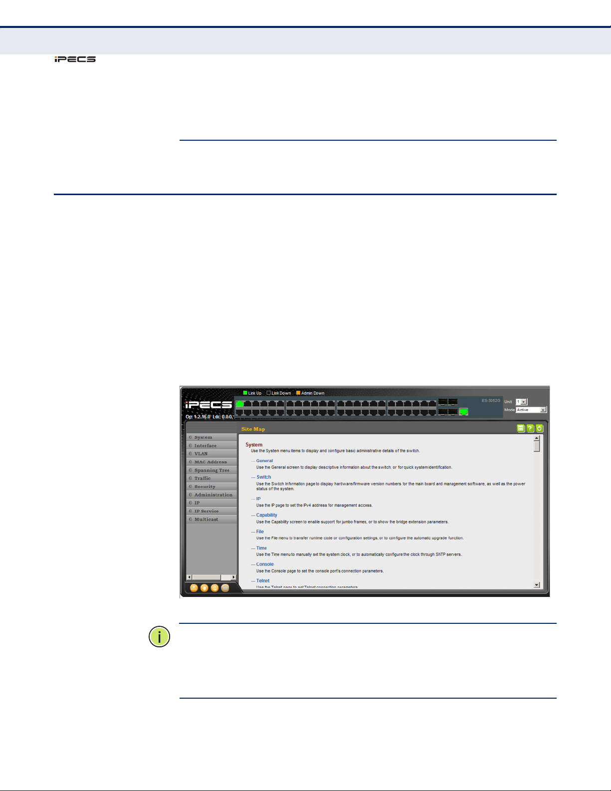
C
ES-3052 Series
HAPTER
Navigating the Web Browser Interface
3
| Using the Web Interface
N
OTE
:
Users are automatically logged off of the HTTP server or HTTPS
server if no input is detected for 600 seconds.
N
OTE
:
Connection to the web interface is not supported for HTTPS using an
IPv6 link local address.
NAVIGATING THE WEB BROWSER INTERFACE
To access the web-browser interface you must first enter a user name and
password. The administrator has Read/Write access to all configuration
parameters and statistics. The default user name and password for the
administrator is “admin.”
HOME PAGE When your web browser connects with the switch’s web agent, the home
page is displayed as shown below. The home page displays the Main Menu
on the left side of the screen and System Information on the right side. The
Main Menu links are used to navigate to other menus, and display
configuration parameters and statistics.
Figure 1: Home Page
N
OTE
:
This manual covers the ES-3052G and ES-3052GP Gigabit Ethernet
switches. Other than the difference in support for PoE (ES-3052GP), there
are no other significant differences. Therefore nearly all of the screen
display examples are based on the ES-3052G. The panel graphics for all of
switch types are shown on the following page.
– 78 –
Page 79
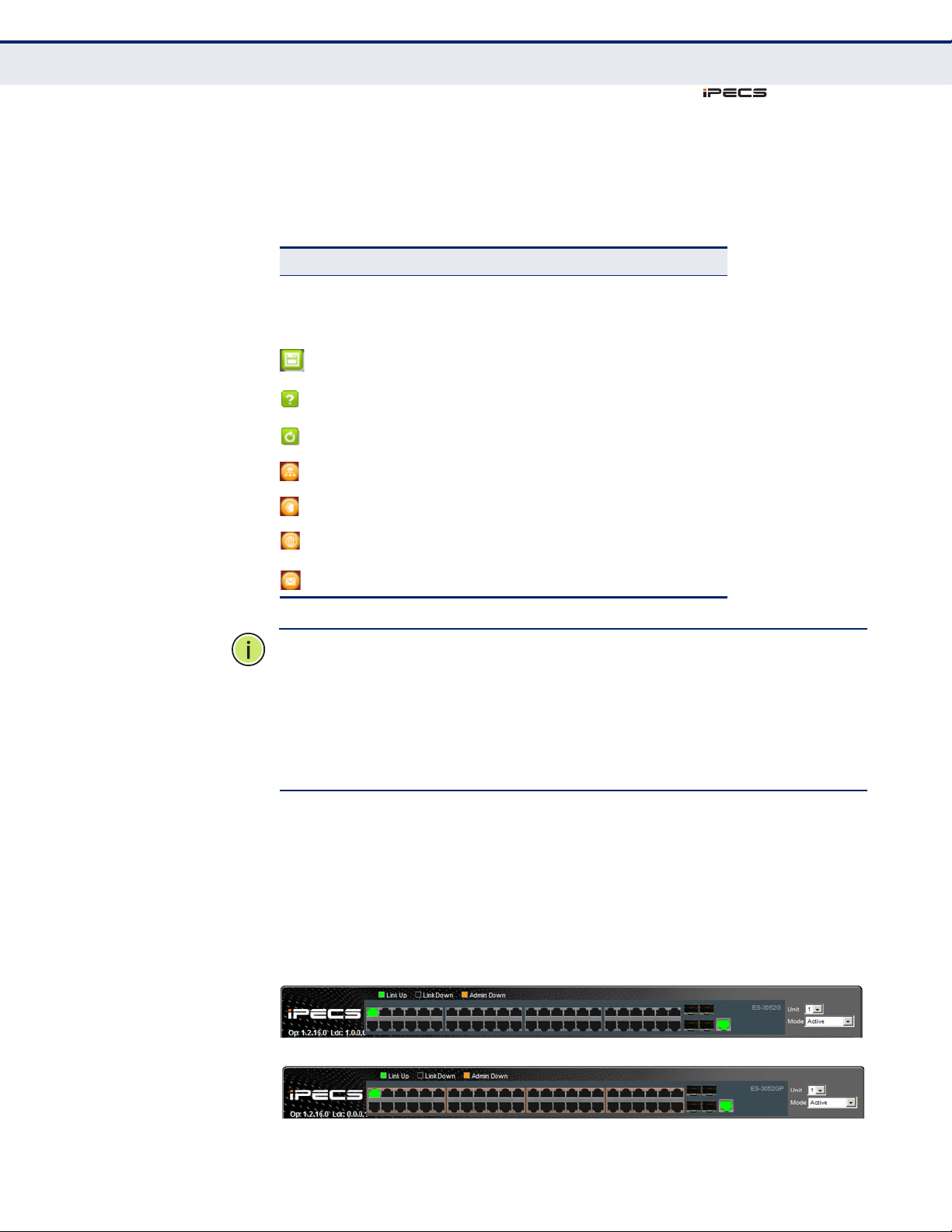
C
ES-3052 Series
ES-3052G
ES-3052GP
HAPTER
Navigating the Web Browser Interface
3
| Using the Web Interface
CONFIGURATION
OPTIONS
Configurable parameters have a dialog box or a drop-down list. Once a
configuration change has been made on a page, be sure to click on the
Apply button to confirm the new setting. The following table summarizes
the web page configuration buttons.
Table 5: Web Page Configuration Buttons
Button Action
Apply Sets specified values to the system.
Revert Cancels specified values and restores current
values prior to pressing “Apply.”
Save current configuration settings.
Displays help for the selected page.
Refreshes the current page.
Displays the site map.
Logs out of the management interface.
Links to the manufacture’s web site.
Sends mail to the manufacturer.
N
OTE
:
To ensure proper screen refresh, be sure that Internet Explorer 5.x
is configured as follows: Under the menu “Tools / Internet Options /
General / Temporary Internet Files / Settings,” the setting for item “Check
for newer versions of stored pages” should be “Every visit to the page.”
N
OTE
:
When using Internet Explorer 5.0, you may have to manually refresh
the screen after making configuration changes by pressing the browser’s
refresh button.
PANEL DISPLAY The web agent displays an image of the switch’s ports. The Mode can be
set to display different information for the ports, including Active (i.e., up
or down), Duplex (i.e., half or full duplex), or Flow Control (i.e., with or
without flow control).
Figure 2: Front Panel Indicators
– 79 –
Page 80
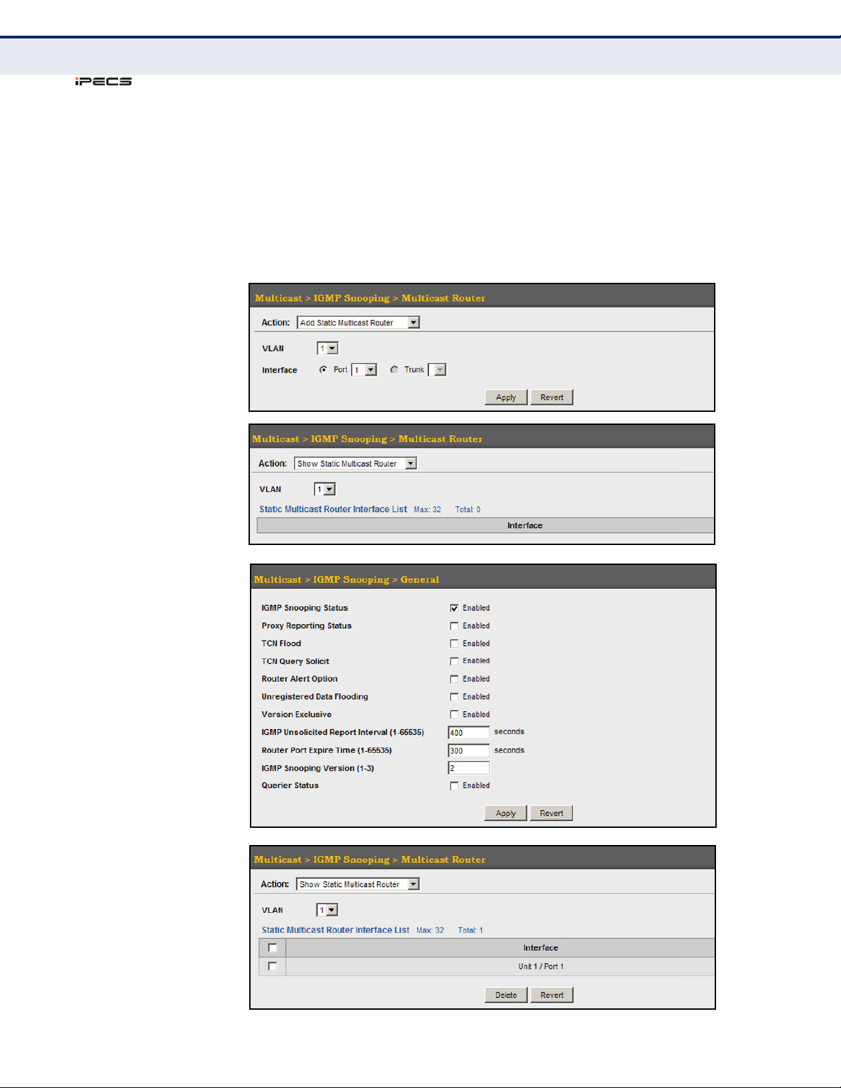
C
ES-3052 Series
HAPTER
Navigating the Web Browser Interface
3
| Using the Web Interface
SHOWING STATUS
INFORMATION
There are various web pages which display configuration settings or the
status of specified processes. Many of these pages will not display any
information unless the switch is properly configured, and in some cases the
interface to which a command applies is up.
For example, if a static router port is configured, the corresponding
information page will not display any information unless IGMP snooping is
first enabled, and the link for the static router port is up.
Figure 3: Displaying Configuration Settings or Status Information
– 80 –
Page 81

C
ES-3052 Series
HAPTER
3
| Using the Web Interface
Navigating the Web Browser Interface
MAIN MENU Using the onboard web agent, you can define system parameters, manage
and control the switch, and all its ports, or monitor network conditions. The
following table briefly describes the selections available from this program.
Table 6: Switch Main Menu
Menu Description Page
System
General Provides basic system description, including contact information 95
Switch Shows the number of ports, hardware version, power status, and
firmware version numbers
IP Sets the IPv4 address for management access 459
Capability Enables support for jumbo frames;
shows the bridge extension parameters
File 101
Copy Allows the transfer and copying files 101
Set Startup Sets the startup file 104
Show Shows the files stored in flash memory; allows deletion of files 104
Automatic Operation Code Upgrade Automatically upgrades operation code if a newer version is
found on the server
Time 110
Configure General
Manually Manually sets the current time 110
SNTP Configures SNTP polling interval 111
Configure Time Server Configures a list of SNTP servers 112
Configure Time Zone Sets the local time zone for the system clock 113
Configure Summer Time Configures summer time settings 114
Console Sets console port connection parameters 116
97
98,
99
105
Telnet Sets Telnet connection parameters 118
CPU Utilization Displays information on CPU utilization 120
Memory Status Shows memory utilization parameters 121
Reload Restarts the switch immediately, at a specified time, after a
Interface 127
Port 127
General
Configure by Port List Configures connection settings per port 127
Configure by Port Range Configures connection settings for a range of ports 130
Show Information Displays port connection status 131
Mirror 132
Add Sets the source and target ports for mirroring 132
Show Shows the configured mirror sessions 132
specified delay, or at a periodic interval
– 81 –
121
Page 82

C
ES-3052 Series
HAPTER
3
| Using the Web Interface
Navigating the Web Browser Interface
Table 6: Switch Main Menu (Continued)
Menu Description Page
Statistics Shows Interface, Etherlike, and RMON port statistics 138
Chart Shows Interface, Etherlike, and RMON port statistics 138
Cable Test Performs cable diagnostics for selected port to diagnose any cable
Tru n k
Static 145
Configure Trunk Creates a trunk, specifying port members 145
Configure General 145
Configure Configures trunk connection settings 145
Show Information Displays trunk connection settings 145
Dynamic 148
Configure Aggregator Configures administration key for specific LACP groups 148
Configure Aggregation Port 145
Configure 145
General Allows ports to dynamically join trunks 148
Actor Configures parameters for link aggregation group members on the
Partner Configures parameters for link aggregation group members on the
Show Information 153
Counters Displays statistics for LACP protocol messages 153
faults (short, open etc.) and report the cable length
local side
remote side
142
148
148
Internal Displays configuration settings and operational state for the local
Neighbors Displays configuration settings and operational state for the
Configure Trunk 148
Show Displays trunk connection settings 148
Configure Configures trunk connection settings 148
Show Member Show port members of dynamic trunks 148
Mirror 158
Add Sets the source trunks and target port for mirroring 158
Show Shows the configured mirror sessions 158
Statistics Shows Interface, Etherlike, and RMON port statistics 138
Chart Shows Interface, Etherlike, and RMON port statistics 138
Green Ethernet Adjusts the power provided to ports based on the length
RSPAN Mirrors traffic from remote switches for analysis at a destination
Traffic Segmentation 162
Configure Global Enables traffic segmentation globally 162
side of a link aggregation
remote side of a link aggregation
of the cable used to connect to other devices
port on the local switch
154
156
160
134
– 82 –
Page 83

C
ES-3052 Series
HAPTER
3
| Using the Web Interface
Navigating the Web Browser Interface
Table 6: Switch Main Menu (Continued)
Menu Description Page
Configure Session Configures the uplink and down-link ports for a segmented group
VLAN Trunking Allows unknown VLAN groups to pass through the specified
VLAN Virtual LAN 167
Static
Configure VLAN Configures VLAN groups, administrative status, and remote type 170
Modify VLAN and Member Ports Configures group name, status, and member attributes 171
Edit Member by Interface Specifies VLAN attributes per interface 171
Edit Member by Interface Range Specifies VLAN attributes per interface range 171
Dynamic
Configure General Enables GVRP VLAN registration protocol globally 176
Configure Interface Configures GVRP status and timers per interface 176
Show Dynamic VLAN 176
Show VLAN Shows the VLANs this switch has joined through GVRP 176
Show VLAN Member Shows the interfaces assigned to a VLAN through GVRP 176
Tunnel IEEE 802.1Q (QinQ) Tunneling 180
Configure Global Sets tunnel mode for the switch 184
Configure Interface Sets the tunnel mode for any participating interface 185
Protocol 187
of ports
interface
163
164
Configure Protocol 187
Add Creates a protocol group, specifying supported protocols 187
Show Shows configured protocol groups 187
Configure Interface 189
Add Maps a protocol group to a VLAN 189
Show Shows the protocol groups mapped to each VLAN 189
IP Subnet 191
Add Maps IP subnet traffic to a VLAN 191
Show Shows IP subnet to VLAN mapping 191
MAC-Based 193
Add Maps traffic with specified source MAC address to a VLAN 193
Show Shows source MAC address to VLAN mapping 193
Mirror 195
Add Mirrors traffic from one or more source VLANs to a target port 195
Show Shows mirror list 195
– 83 –
Page 84

C
ES-3052 Series
HAPTER
3
| Using the Web Interface
Navigating the Web Browser Interface
Table 6: Switch Main Menu (Continued)
Menu Description Page
MAC Address 197
Static 197
Add Configures static entries in the address table 197
Show Displays static entries in the address table 197
Dynamic
Configure Aging Sets timeout for dynamically learned entries 199
Show Dynamic MAC Displays dynamic entries in the address table 200
Clear Dynamic MAC Removes any learned entries from the forwarding database and
clears the transmit and receive counts for any static or system
configured entries
Mirror 202
201
Add Mirrors traffic matching a specified source address from any port
on the switch to a target port
Show Shows mirror list 202
Spanning Tree 205
Loopback Detection Configures Loopback Detection parameters 208
STA Spanning Tree Algorithm
Configure Global
Configure Configures global bridge settings for STP, RSTP and MSTP 209
Show Information Displays STA values used for the bridge 215
Configure Interface
Configure Configures interface settings for STA 216
Show Information Displays interface settings for STA 220
MSTP Multiple Spanning Tree Algorithm 222
Configure Global 222
Add Configures initial VLAN and priority for an MST instance 222
Show Shows configured MST instances 222
Modify Modifies priority for an MST instance 222
Add Member Adds VLAN members for an MST instance 222
202
Show Member Adds or deletes VLAN members for an MST instance 222
Show Information Shows global settings for an MST instance 222
Configure Interface 226
Configure Configures interface settings for an MST instance 226
Show Information Displays interface settings for an MST instance 226
Traffic
Congestion Control
Rate Limit Sets the input and output rate limits for a port 229
Storm Control Sets the traffic storm threshold for each interface 231
– 84 –
Page 85

C
ES-3052 Series
HAPTER
3
| Using the Web Interface
Navigating the Web Browser Interface
Table 6: Switch Main Menu (Continued)
Menu Description Page
Auto Traffic Control Sets thresholds for broadcast and multicast storms which can be
Configure Global Sets the time to apply the control response after traffic has
Configure Interface Sets the storm control mode (broadcast or multicast), the traffic
Priority
Default Priority Sets the default priority for each port or trunk 241
Queue Sets queue mode for the switch; sets the service weight for each
Trust Mode Selects IP Precedence, DSCP or CoS priority processing 248
DSCP to DSCP 249
Add Maps DSCP values in incoming packets to per-hop behavior and
Show Shows the DSCP to DSCP mapping list 249
CoS to DSCP 252
Add Maps CoS/CFI values in incoming packets to per-hop behavior and
Show Shows the CoS to DSCP mapping list 252
PHB to Queue 245
Add Maps internal per-hop behavior values to hardware queues 245
used to trigger configured rate limits or to shut down a port
exceeded the upper threshold, and the time to release the control
response after traffic has fallen beneath the lower threshold
thresholds, the control response, to automatically release a
response of rate limiting, or to send related SNMP trap messages
queue that will use a weighted or hybrid mode
drop precedence values for internal priority processing
drop precedence values for priority processing
234
235
237
242
249
252
Show Shows the PHB to Queue mapping list 245
DiffServ 255
Configure Class 256
Add Creates a class map for a type of traffic 256
Show Shows configured class maps 256
Modify Modifies the name of a class map 256
Add Rule Configures the criteria used to classify ingress traffic 256
Show Rule Shows the traffic classification rules for a class map 256
Configure Policy 259
Add Creates a policy map to apply to multiple interfaces 259
Show Shows configured policy maps 259
Modify Modifies the name of a policy map 259
Add Rule Sets the boundary parameters used for monitoring inbound traffic,
Show Rule Shows the rules used to enforce bandwidth policing for a policy
Configure Interface Applies a policy map to an ingress port 269
and the action to take for conforming and non-conforming traffic
map
259
259
– 85 –
Page 86

C
ES-3052 Series
HAPTER
3
| Using the Web Interface
Navigating the Web Browser Interface
Table 6: Switch Main Menu (Continued)
Menu Description Page
VoIP Voic e o ver IP 271
Configure Global Configures auto-detection of VoIP traffic, sets the Voice VLAN, and
Configure OUI 273
Add Maps the OUI in the source MAC address of ingress packets to the
Show Shows the OUI telephony list 273
Configure Interface Configures VoIP traffic settings for ports, including the way in
VLAN aging time
VoIP device manufacturer
which a port is added to the Voice VLAN, filtering of non-VoIP
packets, the method of detecting VoIP traffic, and the priority
assigned to the voice traffic
272
273
275
Packet Flow Protects against DoS attacks in which the UDP or TCP source port
Security 279
AAA Authentication, Authorization and Accounting 280
System Authentication Configures authentication sequence – local, RADIUS, and TACACS 281
Server 282
Configure Server Configures RADIUS and TACACS server message exchange
Configure Group 282
Add Specifies a group of authentication servers and sets the priority
Show Shows the authentication server groups and priority sequence 282
Accounting Enables accounting of requested services for billing or security
Configure Global Specifies the interval at which the local accounting service updates
Configure Method 287
Add Configures accounting for various service types 287
Show Shows the accounting settings used for various service types 287
Configure Service Sets the accounting method applied to specific interfaces for
or destination port is set to zero
settings
sequence
purposes
information to the accounting server
802.1X, CLI command privilege levels for the console port, and for
Tel n e t
377
282
282
287
287
287
Show Information 287
Summary Shows the configured accounting methods, and the methods
applied to specific interfaces
Statistics Shows basic accounting information recorded for user sessions 287
Authorization Enables authorization of requested services 292
Configure Method 292
Add Configures authorization for various service types 292
Show Shows the authorization settings used for various service types 292
Configure Service Sets the authorization method applied used for the console port,
and for Telnet
– 86 –
287
292
Page 87

C
ES-3052 Series
HAPTER
3
| Using the Web Interface
Navigating the Web Browser Interface
Table 6: Switch Main Menu (Continued)
Menu Description Page
Show Information Shows the configured authorization methods, and the methods
User Accounts 296
Add Configures user names, passwords, and access levels 296
Show Shows authorized users 296
Modify Modifies user attributes 296
Web Authentication Allows authentication and access to the network when 802.1X or
Configure Global Configures general protocol settings 298
Configure Interface Enables Web Authentication for individual ports 299
Network Access MAC address-based network access authentication 300
Configure Global Enables aging for authenticated MAC addresses, and sets the time
Configure Interface 304
General Enables MAC authentication on a port; sets the maximum number
Link Detection Configures detection of changes in link status, and the response
Configure MAC Filter 307
applied to specific interfaces
Network Access authentication are infeasible or impractical
period after which a connected MAC address must be
reauthenticated
of address that can be authenticated, the guest VLAN, dynamic
VLAN and dynamic QoS
(i.e., send trap or shut down port)
292
298
303
304
306
Add Specifies MAC addresses exempt from authentication 307
Show Shows the list of exempt MAC addresses 307
Show Information Shows the authenticated MAC address list 309
HTTPS Secure HTTP 311
Configure Global Enables HTTPs, and specifies the UDP port to use 311
Copy Certificate Replaces the default secure-site certificate 312
SSH Secure Shell 314
Configure Global Configures SSH server settings 317
Configure Host Key 318
Generate Generates the host key pair (public and private) 318
Show Displays RSA and DSA host keys; deletes host keys 318
Configure User Key 320
Copy Imports user public keys from TFTP server 320
Show Displays RSA and DSA user keys; deletes user keys 320
ACL Access Control Lists 322
Configure ACL 324
Show TCAM Shows utilization parameters for TCAM 323
Add Adds an ACL based on IP or MAC address filtering 324
Show Shows the name and type of configured ACLs 324
– 87 –
Page 88

C
ES-3052 Series
HAPTER
3
| Using the Web Interface
Navigating the Web Browser Interface
Table 6: Switch Main Menu (Continued)
Menu Description Page
Add Rule Configures packet filtering based on IP or MAC addresses and other
Show Rule Shows the rules specified for an ACL 324
Configure Interface Binds a port to the specified ACL and time range 339
ARP Inspection 340
Configure General Enables inspection globally, configures validation of additional
Configure VLAN Enables ARP inspection on specified VLANs 343
Configure Interface Sets the trust mode for ports, and sets the rate
Show Information
Show Statistics Displays statistics on the inspection process 346
Show Log Shows the inspection log list 348
IP Filter 349
Add Sets IP addresses of clients allowed management access via the
Show Shows the addresses to be allowed management access 349
Port Security Configures per port security, including status, response for security
Port Authentication IEEE 802.1X 353
packet attributes
address components, and sets the log rate for packet inspection
limit for packet inspection
web, SNMP, and Telnet
breach, and maximum allowed MAC addresses
324
341
345
349
351
Configure Global Enables authentication and EAPOL pass-through 355
Configure Interface Sets authentication parameters for individual ports
Authenticator Sets port authenticator settings 356
Supplicant Sets port supplicant settings 361
Show Statistics Displays protocol statistics for the selected port 363
Authenticator Displays protocol statistics for port authenticator 363
Supplicant Displays protocol statistics for port supplicant 363
IP Source Guard Filters IP traffic based on static entries in the IP Source Guard
table, or dynamic entries in the DHCP Snooping table
Port Configuration Enables IP source guard and selects filter type per port 365
Static Binding 367
Add Adds a static addresses to the source-guard binding table 367
Show Shows static addresses in the source-guard binding table 367
Dynamic Binding Displays the source-guard binding table for a selected interface 369
Administration 379
Log 379
System 379
Configure Global Stores error messages in local memory 379
365
Show Logs Shows logged error messages 379
– 88 –
Page 89

C
ES-3052 Series
HAPTER
3
| Using the Web Interface
Navigating the Web Browser Interface
Table 6: Switch Main Menu (Continued)
Menu Description Page
Remote Configures the logging of messages to a remote logging process 382
SMTP Sends an SMTP client message to a participating server 383
Configure Server Configures a list of recipient SMTP servers 383
Add Adds a recipient SMTP server 383
Show Shows configured SMTP servers 383
Configure General Sets SMTP status, e-mail source and destination addresses 383
LLDP 387
Configure Global Configures global LLDP timing parameters 387
Configure Interface
Configure General Sets the message transmission mode, enables SNMP notification,
Add CA-Type Specifies the location of the device attached to an interface 393
Show CA-Type Shows the location of the device attached to an interface 393
Modify CA-Type Modifies the location of the device attached to an interface 393
Show Local Device Information 396
General Displays general information about the local device 396
Port/Trunk Displays information about each interface 396
Show Remote Device Information 399
Port/Trunk Displays information about a remote device connected to a port on
Port/Trunk Details Displays detailed information about a remote device connected to
Show Device Statistics 404
General Displays statistics for all connected remote devices 404
Port/Trunk Displays statistics for remote devices on a selected port or trunk 404
PoE Power over Ethernet 406
Configure Global Displays the power budget for the switch 407
Configure Interface Configures port power parameters 408
SNMP Simple Network Management Protocol 410
and sets the LLDP attributes to advertise
this switch
this switch
389
399
399
Configure Global Enables SNMP agent status, and sets related trap functions 412
Configure Engine 413
Set Engine ID Sets the SNMP v3 engine ID on this switch 413
Add Remote Engine Sets the SNMP v3 engine ID for a remote device 414
Show Remote Engine Shows configured engine ID for remote devices 414
– 89 –
Page 90

C
ES-3052 Series
HAPTER
3
| Using the Web Interface
Navigating the Web Browser Interface
Table 6: Switch Main Menu (Continued)
Menu Description Page
Configure View 416
Add View Adds an SNMP v3 view of the OID MIB 416
Show View Shows configured SNMP v3 views 416
Add OID Subtree Specifies a part of the subtree for the selected view 416
Show OID Subtree Shows the subtrees assigned to each view 416
Configure Group 419
Add Adds a group with access policies for assigned users 419
Show Shows configured groups and access policies 419
Configure User
Add Community Configures community strings and access mode 423
Show Community Shows community strings and access mode 423
Add SNMPv3 Local User Configures SNMPv3 users on this switch 424
Show SNMPv3 Local User Shows SNMPv3 users configured on this switch 424
Change SNMPv3 Local User Group Assign a local user to a new group 424
Add SNMPv3 Remote User Configures SNMPv3 users from a remote device 426
Show SNMPv3 Remote User Shows SNMPv3 users set from a remote device 424
Configure Notification 429
Add Configures notification managers to receive messages on key
events that occur this switch
Show Shows configured notification managers 429
RMON Remote Monitoring 434
Configure Global
Add
Alarm Sets threshold bounds for a monitored variable 434
Event Creates a response event for an alarm 437
Show
Alarm Shows all configured alarms 434
Event Shows all configured events 437
Configure Interface
Add
History Periodically samples statistics on a physical interface 440
Statistics Enables collection of statistics on a physical interface 443
Show
429
History Shows sampling parameters for each entry in the history group 440
Statistics Shows sampling parameters for each entry in the statistics group 443
– 90 –
Page 91

C
ES-3052 Series
HAPTER
3
| Using the Web Interface
Navigating the Web Browser Interface
Table 6: Switch Main Menu (Continued)
Menu Description Page
Show Details
History Shows sampled data for each entry in the history group 440
Statistics Shows sampled data for each entry in the history group 443
Cluster 446
Configure Global Globally enables clustering for the switch; sets Commander status 447
Configure Member
Add Adds switch Members to the cluster 448
Show Shows cluster members 448
Show Candidate Shows cluster candidates 448
Show Member Shows cluster switch member; managed switch members 450
Time Range Sets active time range for various functions, including ACL and PoE 451
Add Specifies the name of a time range 451
Show Shows the name of configured time ranges 451
Add Rule 451
Absolute Sets exact time or time range 451
Periodic Sets a recurrent time 451
Show Rule Shows the time specified by a rule 451
IP 455
General
Ping Sends ICMP echo request packets to another node on the network 455
ARP Address Resolution Protocol 457
Configure General Sets the aging time for dynamic entries in the ARP cache 457
Show Information Shows entries in the Address Resolution Protocol (ARP) cache 458
IPv6 Configuration 462
Configure Global Sets an IPv6 default gateway for traffic with no known next hop 462
Configure Interface Configures IPv6 interface address using auto-configuration or link-
Add IPv6 Address Adds an global unicast, EUI-64, or link-local IPv6 address to an
Show IPv6 Address Show the IPv6 addresses assigned to an interface 467
Show IPv6 Neighbor Cache Displays information in the IPv6 neighbor discovery cache 469
Show Statistics 471
IPv6 Shows statistics about IPv6 traffic 471
local address, and sets related protocol settings
interface
463
465
ICMPv6 Shows statistics about ICMPv6 messages 471
UDP Shows statistics about UDP messages 471
– 91 –
Page 92

C
ES-3052 Series
HAPTER
3
| Using the Web Interface
Navigating the Web Browser Interface
Table 6: Switch Main Menu (Continued)
Menu Description Page
IP Service 477
DNS Domain Name Service
General 477
Configure Global Enables DNS lookup; defines the default domain name appended
Add Domain Name Defines a list of domain names that can
Show Domain Names Shows the configured domain name list 478
Add Name Server Specifies IP address of name servers for dynamic lookup 480
Show Name Servers Shows the name server address list 480
Static Host Table 481
Add Configures static entries for domain name to address mapping 481
Show Shows the list of static mapping entries 481
Modify Modifies the static address mapped to the selected host name 481
Cache Displays cache entries discovered by designated
DHCP Dynamic Host Configuration Protocol
Snooping 370
Configure Global Enables DHCP snooping globally, MAC-address verification,
Configure VLAN Enables DHCP snooping on a VLAN 374
Configure Interface Sets the trust mode for an interface 375
to incomplete host names
be appended to incomplete host names
name servers
information option; and sets the information policy
477
478
483
373
Show Information Displays the DHCP Snooping binding information 376
Multicast 485
IGMP Snooping 486
General Enables multicast filtering; configures parameters for multicast
Multicast Router 491
Add Static Multicast Router Assigns ports that are attached to a neighboring multicast router 491
Show Static Multicast Router Displays ports statically configured as attached to a neighboring
Show Current Multicast Router Displays ports attached to a neighboring multicast router, either
IGMP Member 493
Add Static Member Statically assigns multicast addresses to the selected VLAN 493
Show Static Member Shows multicast addresses statically configured on the selected
Show Current Member Shows multicast addresses associated with the selected VLAN,
snooping
multicast router
through static or dynamic configuration
VLAN
either through static or dynamic configuration
488
491
491
493
493
– 92 –
Page 93

C
ES-3052 Series
HAPTER
3
| Using the Web Interface
Navigating the Web Browser Interface
Table 6: Switch Main Menu (Continued)
Menu Description Page
Interface 496
Configure Configures IGMP snooping per VLAN interface 496
Show Shows IGMP snooping settings per VLAN interface 496
Forwarding Entry Displays the current multicast groups learned through IGMP
Filter 502
Configure General Enables IGMP filtering for the switch 502
Configure Profile 503
Add Adds IGMP filter profile; and sets access mode 503
Show Shows configured IGMP filter profiles 503
Add Multicast Group Range Assigns multicast groups to selected profile 503
Show Multicast Group Range Shows multicast groups assigned to a profile 503
Configure Interface Assigns IGMP filter profiles to port interfaces and sets throttling
MVR Multicast VLAN Registration 507
Configure General Globally enables MVR, sets the MVR VLAN, adds multicast
Configure Interface Configures MVR interface type and immediate leave mode; also
Configure Static Group Member 512
Add Statically assigns MVR multicast streams to an interface 512
Show Shows MVR multicast streams assigned to an interface 512
Show Member Shows the interfaces associated with multicast groups assigned to
Snooping
action
stream addresses
displays MVR operational and active status
the MVR VLAN
501
506
509
510
514
– 93 –
Page 94

C
ES-3052 Series
HAPTER
3
| Using the Web Interface
Navigating the Web Browser Interface
– 94 –
Page 95

ES-3052 Series
4 BASIC MANAGEMENT TASKS
This chapter describes the following topics:
◆ Displaying System Information – Provides basic system description,
including contact information.
◆ Displaying Switch Hardware/Software Versions – Shows the hardware
version, power status, and firmware versions
◆ Configuring Support for Jumbo Frames – Enables support for jumbo
frames.
◆ Displaying Bridge Extension Capabilities – Shows the bridge extension
parameters.
◆ Managing System Files – Describes how to upgrade operating software
or configuration files, and set the system start-up files.
◆ Setting the System Clock – Sets the current time manually or through
specified SNTP servers.
◆ Configuring the Console Port – Sets console port connection
parameters.
◆ Configuring Telnet Settings – Sets Telnet connection parameters.
◆ Displaying CPU Utilization – Displays information on CPU utilization.
◆ Displaying Memory Utilization – Shows memory utilization parameters.
◆ Resetting the System – Restarts the switch immediately, at a specified
time, after a specified delay, or at a periodic interval.
DISPLAYING SYSTEM INFORMATION
Use the System > General page to identify the system by displaying
information such as the device name, location and contact information.
CLI REFERENCES
◆ "System Management Commands" on page 537
◆ "SNMP Commands" on page 593
– 95 –
Page 96
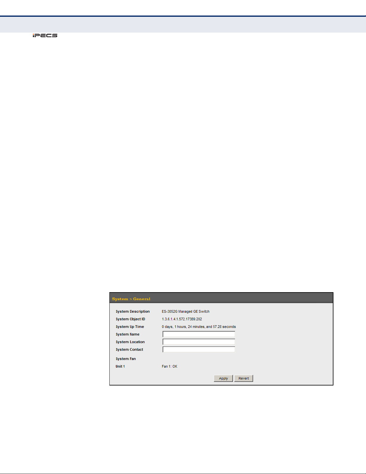
C
ES-3052 Series
HAPTER
Displaying System Information
4
| Basic Management Tasks
PARAMETERS
These parameters are displayed in the web interface:
◆ System Description – Brief description of device type.
◆ System Object ID – MIB II object ID for switch’s network
◆ System Up Time – Length of time the management agent has been
◆ System Name – Name assigned to the switch system.
◆ System Location – Specifies the system location.
◆ System Contact – Administrator responsible for the system.
◆ System Fan – Shows the current status of all system fans.
management subsystem.
(ES-3052G: 1.3.6.1.4.1.572.17389.202,
ES-3052GP: 1.3.6.1.4.1.572.17389.201)
up.
The number of fans provided: ES-3052G - 1, 3052GP - 3
WEB INTERFACE
To configure general system information:
1. Click System, General.
2. Specify the system name, location, and contact information for the
system administrator.
3. Click Apply.
Figure 4: System Information
– 96 –
Page 97

C
ES-3052 Series
Displaying Switch Hardware/Software Versions
DISPLAYING SWITCH HARDWARE/SOFTWARE VERSIONS
Use the System > Switch page to display hardware/firmware version
numbers for the main board and management software, as well as the
power status of the system.
CLI REFERENCES
◆ "System Management Commands" on page 537
PARAMETERS
The following parameters are displayed in the web interface:
Main Board Information
◆ Serial Number – The serial number of the switch.
◆ Number of Ports – Number of built-in ports.
◆ Hardware Version – Hardware version of the main board.
HAPTER
4
| Basic Management Tasks
◆ Internal Power Status – Displays the status of the internal power
supply.
Management Software Information
◆ Role – Shows that this switch is operating as Master or Slave.
◆ CPLD Version – Version number of Complex Programmable Logic
Device.
◆ Loader Version – Version number of loader code.
◆ Operation Code Version – Version number of runtime code.
– 97 –
Page 98
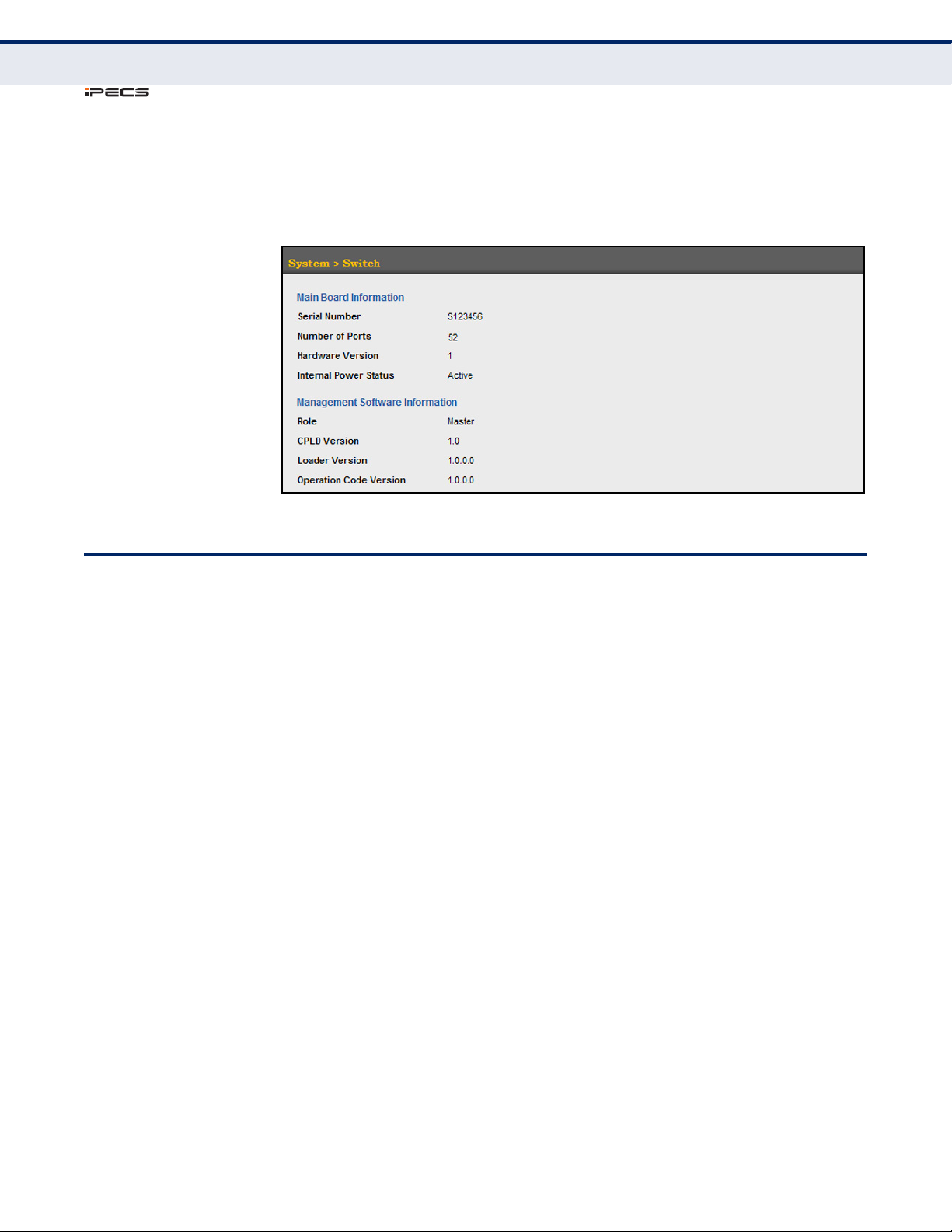
C
ES-3052 Series
HAPTER
Configuring Support for Jumbo Frames
4
| Basic Management Tasks
WEB INTERFACE
To view hardware and software version information.
1. Click System, then Switch.
Figure 5: General Switch Information
CONFIGURING SUPPORT FOR JUMBO FRAMES
Use the System > Capability page to configure support for jumbo frames.
The switch provides more efficient throughput for large sequential data
transfers by supporting jumbo frames up to 10240 bytes for Gigabit
Ethernet. Compared to standard Ethernet frames that run only up to
1.5 KB, using jumbo frames significantly reduces the per-packet overhead
required to process protocol encapsulation fields.
CLI REFERENCES
◆ "System Management Commands" on page 537
USAGE GUIDELINES
To use jumbo frames, both the source and destination end nodes (such as
a computer or server) must support this feature. Also, when the connection
is operating at full duplex, all switches in the network between the two end
nodes must be able to accept the extended frame size. And for half-duplex
connections, all devices in the collision domain would need to support
jumbo frames.
PARAMETERS
The following parameters are displayed in the web interface:
◆ Jumbo Frame – Configures support for jumbo frames.
(Default: Disabled)
– 98 –
Page 99
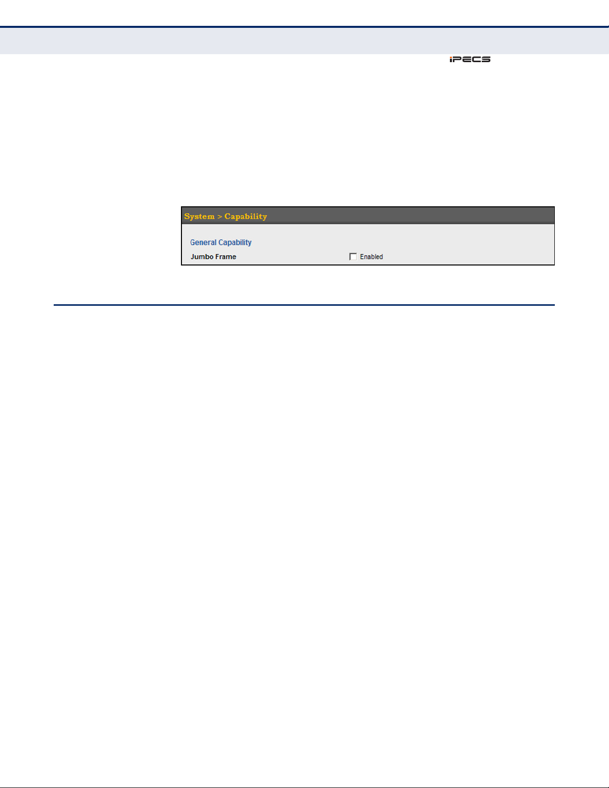
ES-3052 Series
WEB INTERFACE
To configure support for jumbo frames:
1. Click System, then Capability.
2. Enable or disable support for jumbo frames.
3. Click Apply.
Figure 6: Configuring Support for Jumbo Frames
DISPLAYING BRIDGE EXTENSION CAPABILITIES
C
HAPTER
Displaying Bridge Extension Capabilities
4
| Basic Management Tasks
Use the System > Capability page to display settings based on the Bridge
MIB. The Bridge MIB includes extensions for managed devices that support
Multicast Filtering, Traffic Classes, and Virtual LANs. You can access these
extensions to display default settings for the key variables.
CLI REFERENCES
◆ "GVRP and Bridge Extension Commands" on page 844
PARAMETERS
The following parameters are displayed in the web interface:
◆ Extended Multicast Filtering Services – This switch does not
support the filtering of individual multicast addresses based on GMRP
(GARP Multicast Registration Protocol).
◆ Traffic Classes – This switch provides mapping of user priorities to
multiple traffic classes. (Refer to "Class of Service" on page 241.)
◆ Static Entry Individual Port – This switch allows static filtering for
unicast and multicast addresses. (Refer to "Setting Static Addresses"
on page 197.)
◆ VLAN Version Number – Based on IEEE 802.1Q, “1” indicates Bridges
that support only single spanning tree (SST) operation, and “2”
indicates Bridges that support multiple spanning tree (MST) operation.
◆ VLAN Learning – This switch uses Independent VLAN Learning (IVL),
where each port maintains its own filtering database.
◆ Local VLAN Capable – This switch does not support multiple local
bridges outside of the scope of 802.1Q defined VLANs.
– 99 –
Page 100
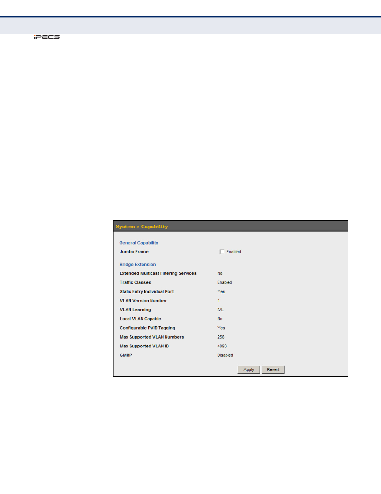
C
ES-3052 Series
HAPTER
Displaying Bridge Extension Capabilities
4
| Basic Management Tasks
◆ Configurable PVID Tagging – This switch allows you to override the
default Port VLAN ID (PVID used in frame tags) and egress status
(VLAN-Tagged or Untagged) on each port. (Refer to "VLAN
Configuration" on page 167.)
◆ Max Supported VLAN Numbers – The maximum number of VLANs
supported on this switch.
◆ Max Supported VLAN ID – The maximum configurable VLAN
identifier supported on this switch.
◆ GMRP – GARP Multicast Registration Protocol (GMRP) allows network
devices to register end stations with multicast groups. This switch does
not support GMRP; it uses the Internet Group Management Protocol
(IGMP) to provide automatic multicast filtering.
WEB INTERFACE
To view Bridge Extension information:
1. Click System, then Capability.
Figure 7: Displaying Bridge Extension Configuration
– 100 –
 Loading...