

Page 1

iPECS eMG80
System DECT Installation Guide
Please read this manual carefully before operating System.
Retain it for future reference.
Page 2

iPECS eMG80
System DECT Installation Guide Issue 1.3
Regulatory Information
Before making connections to the telephone network, you may be required to notify your local
serving telephone company of your intention to use "customer provided equipment.” You may
further be required to provide any or all of the following information:
PSTN line Telephone numbers to be connected to the system
Model name iPECS eMG80 DECT
The required regulatory agency registration number is available from your local Ericsson-LG
Enterprise representative.
This equipment complies with the following regulatory standards, EN 301, EN 406, TBR 10 and
TBR 22. Also, this equipment complies with the safety requirements of EN 60950-1 and the EMC
requirements of EN5022, EN5024, EN301 489-1 and EN 301 489-6.
GDC-450/500H has been designed to comply with the Hearing Aid Compatibility requirements as
defined in Section 68.316 of Part 68 F CC Rules.
If the telephone company determines that customer provided equipment is faulty and may
possibly cause harm or interruption in service to the telephone network, it should be disconnected
until repair can be affected. If this is not done, the telephone company may temporarily
discon nect you r service.
The local telephone company may make changes in its communications facilities or procedures.
If these changes could reasonably be expected to affect the use of iPECS eMG80 or compatibility
with the network, the telephone company is required to give advanced written notice to the user,
allowing the user to take appropriate steps to maintain telephone service.
iPECS eMG80 complies with rules regarding radiation and radio frequency emission as defined
by local regulatory agencies. In accordance with these agencies, you may be required to provide
information such as the following to the end user:
WARNING
“This equipment generates and uses R.F. energy, and if not insta lled and used in
accordance with the Instruction Manual, it may cause interference to radio
communications. It has been tested and found to comply with the appro priate limits for a
telecommunication device. The limits are designed to provide reasonable protection
against such interference, when operated in a commercial environment. Operation of this
equipment in a residential area could cause interference, in which case the user, at his
own expense, will be required to take whatever measures may be required to correct the
interference.”
Page 3

iPECS eMG80
System DECT Installation Guide Issue 1.3
Revision History
Copyright© 2013 Ericsson-LG Enterprise Co., Ltd. All Rights Reserved
This material is copyrighted by Ericsson-LG E nterprise Co., Ltd. (Ericsson-LG Enterprise). Any
unauthorized repr oductions, use or disclosure of this material, or any part thereof, is strictly prohibited
and is a violation of Copyright Laws. Ericsson-LG Enterprise reserves the right to make changes in
specifications at any time without notice. The inform ation furnished by Ericsson-LG Ent er pr ise in t his
material is believed to be accurate and r eliable, but is not warranted to be true in all cases. If yo u are not
the intended reci pient, you should destroy or retrieve this material to Ericsson-LG Enterprise.
iPECS is trademark of Ericsson-LG Enterprise Co., Ltd .
All other brand and product names are trademarks or registered trademarks of their respective companies.
SW version ISSUE DATE DESCRIPTION OF CHANGES
1.0.x
1.0
Sep., 2013
Initial Release
1.1.x 1.1 Dec., 2013 Changed Ericsson-LG to Ericsson-LG Enterprise
1.2.x
1.2
June, 2015
Changed LG logotype
2.0.x 1.3 Jan., 2016 Added GDC-480H and corrected the wrong operation in
subscription and Attendant service
Page 4

iPECS eMG80
System DECT Installation Guide Issue 1.3
i
Table of Contents
1. Introduction .........................................................................1
2. System D ECT Compone nts & S pec if ications
.....................2
2.1 General Specifications .................................................................. 3
2.2 WTIB4 Specifications
.................................................................... 3
2.3 GDC-600BE Specifications
........................................................... 3
2.4 GDC-450H/480H/500H Specifications
........................................... 4
3. Installation ...........................................................................5
3.1 Installation Overview ..................................................................... 5
3.2 Site Planning for Base Stations
.................................................... 5
3.2.1 Ce ll -coverage Region Survey (CRS) ...................................................... 5
3.2.2 Preliminary Positions of Base S tations .................................................... 6
3.2.3 General Procedure for CRS .................................................................... 9
3.2.3.1 Additional Tips for CRS ...................................................................... 10
3.2.4 Base Station General Guidelines .......................................................... 11
3.3 WTIB4 ............................................................................................ 14
3.3.1 Pin Assignment .................................................................................... 15
3.3.2 Connectors, Switch and LED Functions ................................................ 15
3.4 Description and Installation of GDC-600BE .............................. 17
3.4.1 GD C -600E Description ......................................................................... 17
3.4.2 Base Station Installation ....................................................................... 17
3.4.2.1 Mounting Base Station ....................................................................... 18
3.4.2.2 Mounting Base Station - 2 (Using Wedge)
.......................................... 19
3.4.2.3 LED Indications
................................................................................. 20
3.4.2.4 Traffic Guidelines
............................................................................... 20
3.5 Ferrite Core Installation and Wiring ........................................... 21
3.6 User Subscription/Unsubscription
............................................. 23
3.6.1 System ID ............................................................................................. 23
3.6.2 Authentication Code ............................................................................. 24
3.6.3 Us e r S ub script io n ................................................................................. 25
3.6.4 User Unsubscription I ........................................................................... 26
3.6.5 Us e r U ns u bscription II .......................................................................... 27
3.6.6 RSSI Monitoring ................................................................................... 28
Page 5

iPECS eMG80
System DECT Installation Guide Issue 1.3
ii
4. Attendant Services ............................................................ 29
4.1 Enable Subscription .................................................................... 30
4.2 Terminate a Subscription
............................................................ 31
4.3 Authentication Code for DECT Subscription
............................ 32
4.4 Viewing the System ID (PARK code)
.......................................... 33
4.5 Authenticating a User
.................................................................. 34
4.6 Modifying the System ID (PARK code)
...................................... 35
4.7 Deleting all Subscriptions
........................................................... 36
4.8 Deleting a Single Subscription
................................................... 37
4.9 Registering to a Networked System
........................................... 38
5. Troubleshooting ................................................................ 39
Page 6
iPECS eMG80
System DECT Installation Guide Issue 1.3
1
1. INTRODUCTION
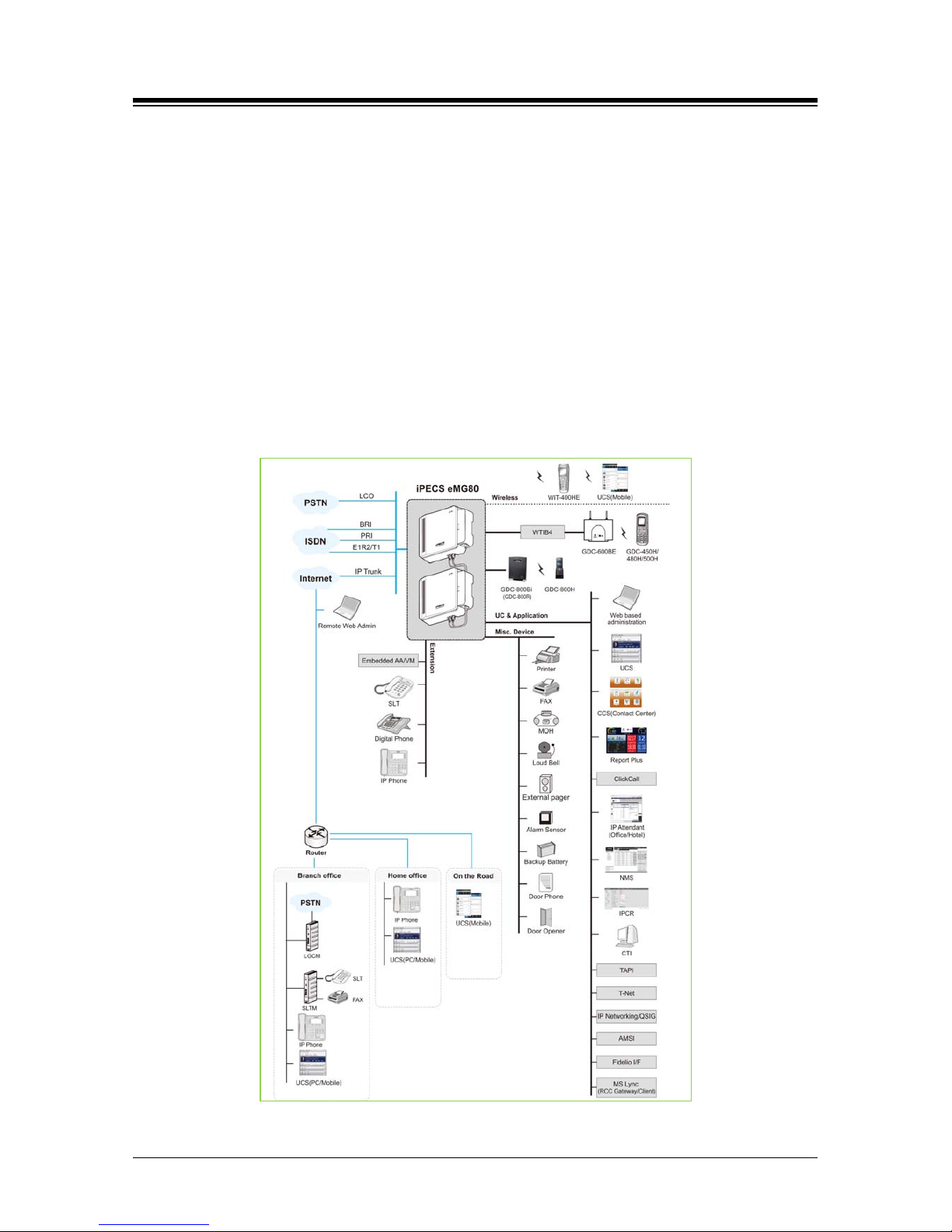
iPECS eMG80 DECT (Dig ital Eu ro Cordless Technology) solution employs Ericsson-LG
Enterprise DECT technology to provide convenience and enhanced productivity with increased
office mobility. With the System DECT solution, any DECT Gap compatible handset such as the
Ericsson-LG En terpr ise GDC-450H/480H/500H DECT handset can use wireless connectivity for
accessing features and functions of the iPECS system. GDC-450H/480H/500H connect with
Ericsson-LG En terpr ise DECT Base Stations, providing a fixed radio coverage area or cell.
Arranging multiple base stations with overlapping cells forms zones of transparent coverage. As
the handset is moved within the zone, a Radio Frequency (RF) connection can be established
with any Base station in the zone for transparent operation of the handset throughout the zone,
using active call hand-off.
Figure 1.1-1 System Connection Diagram
Page 7
iPECS eMG80
System DECT Installation Guide Issue 1.3
2
2. SYSTEM DECT COMPONENTS &
SPECIFICATIONS
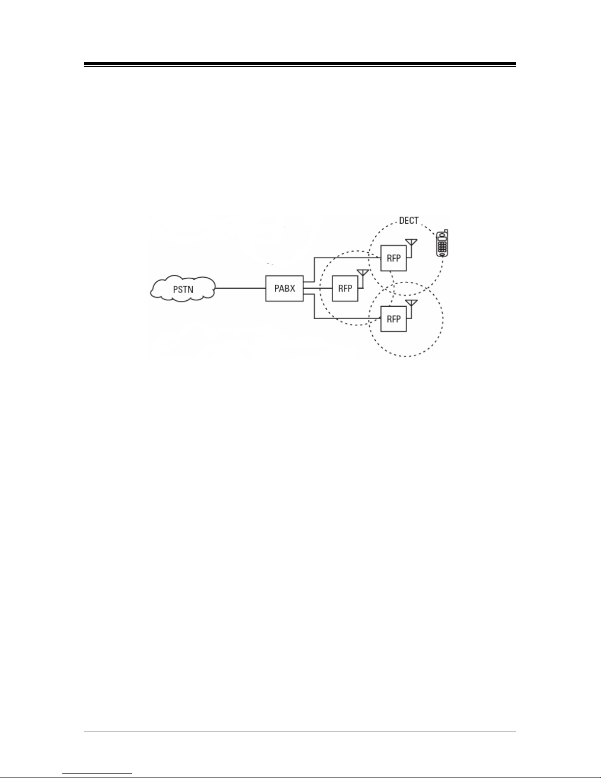
The System DECT solution works well with iPECS eMG80 System which is comprised of WTIB4,
Base Station (RPF), and DE CT term inal. The next figure shows a general DECT reference model
of Wireless Office Terminal System (WOTS).
Figure 2.1 General DECT reference model of Wireless Office Terminal System
PABX – Private Automatic Branch Exchange
RFP – Radio Fixed Part (Base Station)
PSTN – Public Switched Telephone Network
The following is needed to configure the System using DECT phones:
WTIB4 board –One WTIB4 can be connected to the iPECS eMG80 System. WTIB4
can support up t o four Base Stati o ns.
Base Station (GDC-600BE) – The Base St a ti on c an pr ocess up to six si m ul t aneous
calls. The Base Station should be installed indoors and protected from surge because
it is designed for indoor station.
W ireless Terminal (GDC-450H/480H/500H) – Up to 48 wireless ter m i n al s ca n be
registered.
Page 8

iPECS eMG80
System DECT Installation Guide Issue 1.3
3
2.1 General Specifications
Table 2.1-1 Enviro nm ental Specifications
ITEM DEGREES (℃) DEGREES (℉)
Operation T emperatu r e
0~40
32~104
Optimum Operation Temperature
20~26
68~78
Storage Temperature
10~70
32~158
Relative Humidity
0~80% non-condensing
2.2 WTIB4 Specifications
ITEM SPECIFICATION
WTIB4
Power Consumption
3.3W (= 660mA @ +5V)
DECT base station connection port
4
DECT base station interface
E1(line coding : HDB3)
DECT base station feeding voltage
+30V (±2.5%)
Seri al Port for GDK-TRC1
1 (115,200bps); ELG propriet ary 4-pin serial interface
2.3 GDC-600BE Specifications
Table 2.3-1 Base Station Specif i cations
ITEM SPECIFICATION
Power feeding +30VDC
Transmission Max Power 250mW
100mW(USA)
Access Method/Duplex TDMA/TDD
Frequency Band 1,880~1,900MHz
1920~1930MHz (USA)
Channel Spacing 1.728MHz
Modulation GFSK
Data rate 1.152Mbps
Max. Base Station distance from the WTIB4 600m (twisted 2-pair cable)
Page 9

iPECS eMG80
System DECT Installation Guide Issue 1.3
4
2.4 GDC-450H/480H/500H Specificatio n s
Battery type, battery life, charger/base input voltage and current, charger output voltage and
current, minimum receive power for operation, etc.
Table 2.4-1 Wireless Terminal Specifications
ITEM SPECIFICATION
Max. T ransm ission Power 250mW maximum
100mW(USA) maximum
Modulation Method GFSK
Frequency Band 1,880MHz~1,900MHz
1920~1930MHz (USA)
Page 10

iPECS eMG80
System DECT Installation Guide Issue 1.3
5
3. INSTALLATION
3.1 Installation Overview
The installation of System DECT begins with a Site Survey to establish a temporary site map
including initial locations for Base Stations. After the site map is developed, the WTIB(s) is
installed and the iPECS is configured to support System DECT (refer to your system
iPECS
eMG80 Admini stration and Programming Manual
DECT employs RF sign al s to c om municate between the handsets and Base Stations.
for establishing DECT data in Web Admin).
Once configuration is complete, the Base Stations are mounted in their preliminary locations and
an RF coverage survey is conducted to refine the Base Station locations. With the Base Stations
placed and installed in their permanent locations, handsets can be registered to System DECT.
In order to address the variation in range, prior to installation, a site survey should be conducted
to establish a map with the preliminary locations for the DECT Base Stations. After installation,
the handset is employed in the Cell Tool mode to define the actual RF radiation pattern and Base
Station locations can be adjusted to provide seamless coverage.
3.2 Site Planning for Base Stations
The purpose of Site Planning is to provide you with information and explain tasks that should be
considered to ensure the best operation of the system. Read the following information before
installing the unit.
CAUTION
The Base Station should be installed indoors and protected from surge because it
is designed to be an indoor station.
3.2.1 Cell-coverage Region Survey (CRS)
In order to obtain the most complete coverage in your facility, this Section explains the measuring
procedures using the Cell-coverage Region Survey (CRS) tool of GDC-600TBE. The temporary
positions of Base Stations should be determined prior to this measurement according to
instructions outlined in this section. The temporary positions will be adjusted according to the
measurement findings, if necessary. Before reading this part, it is recommended to get used to
the manipulation of the CRS tool. GDC-450H/480H/500H supports CRS function.
Page 11
iPECS eMG80
System DECT Installation Guide Issue 1.3
6
3.2.2 Preliminary Positions of Base Stations
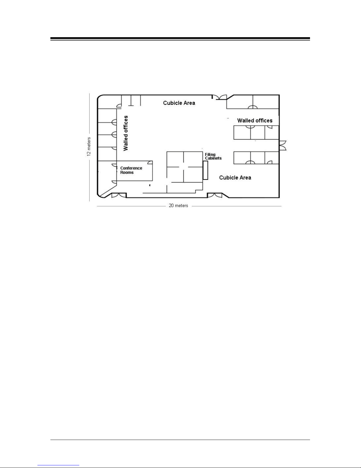
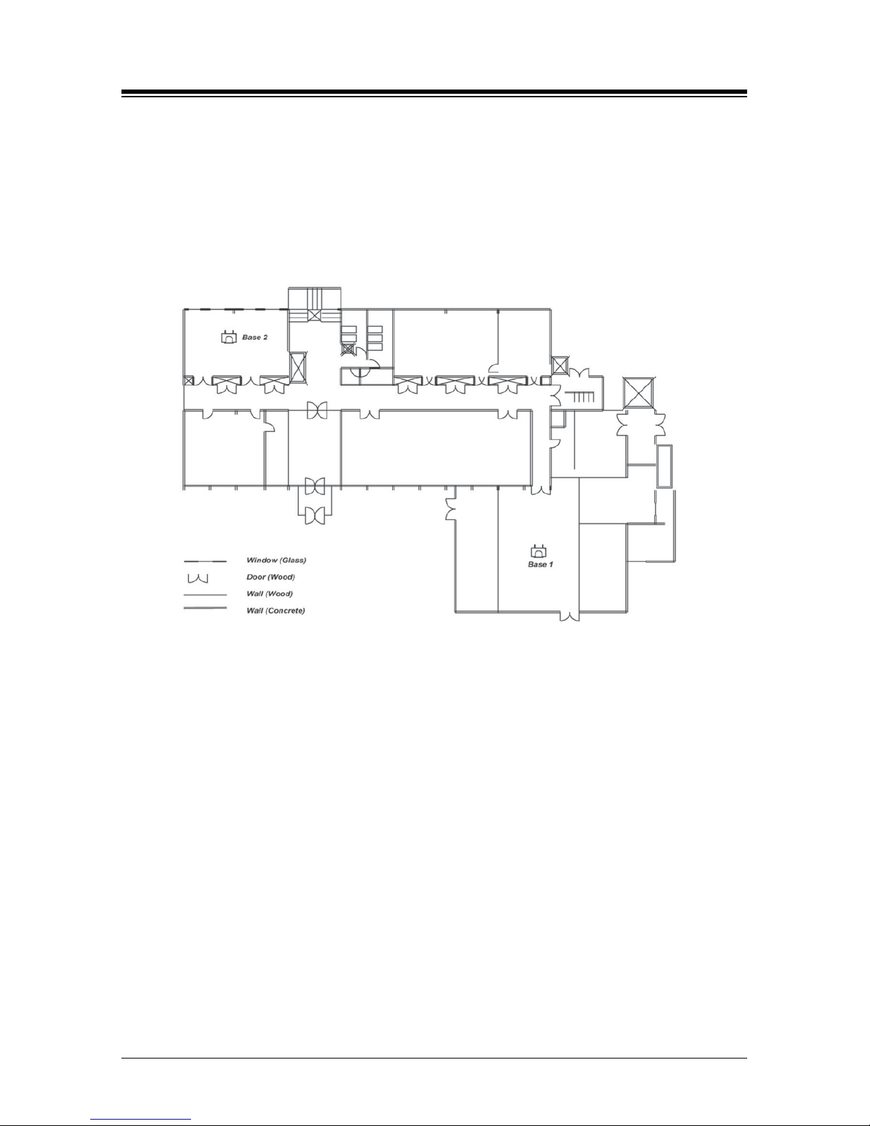
1. Obtain the plane drawings of the building.
First, understand the general constructing materials of the walls, doors, windows, etc.
The materials of the building are the main factors of attenuation of the RF signals.
Figure 3.2.2-1 DECT Site Survey
As the Base Station or Handset RF signal propagates, it is subject to several
characteristics that affect the ability to receive the signal in a useable form. N or mal
attenuation, reflection, and noise all contribute to signal degradation over distance. The
Base Station and Handset transmit at about 10 dbm and can receive a signal of -70
dbm. In an open field with line-of-sight, the handset and Base station can have a
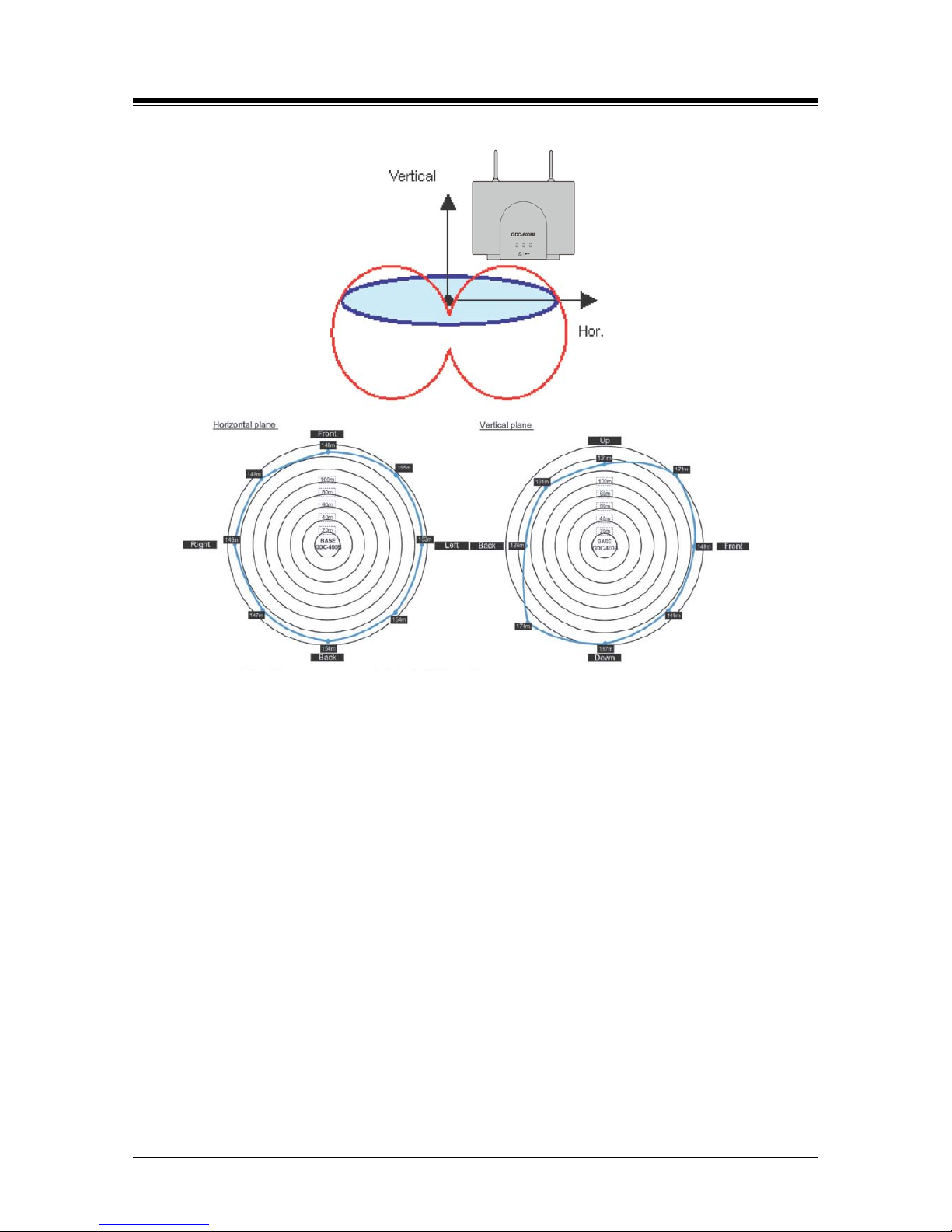
separation of about 175 meters. The antenna radiation pattern is approximately circular
in the horizontal plane (shown Figure 3.2.2-2). In an office environment, walls, doors,
windows, etc. will further attenuate the RF signal to varying degrees (guidelines below),
significantly reducing the coverage area.
Page 12
iPECS eMG80
System DECT Installation Guide Issue 1.3
7
Figure 3.2.2-2 A n t enna Radi at ion P at tern
Office furniture and structures such as filing cabinets, and certain windows and other
surfaces can cause reflections of the original signal. Some materials cause significant
reflections, which can reduce the received signal. GDC-600BE has two antennas to
implement antenna diversity, which minimizes the affects of signal reflections. By
employing the antenna with the best signal, the affects of reflected signals can be
reduced. Although reflections cannot be eliminated in an office, consider locating the
Base Stations away from cabinets and other tall furniture.
High noise levels affect the ability of the receiver to separate the desired signal from the
general noise. Office and industrial equipments such as Fax machines, office
electronics, welders, microwave ovens and even poorly maintained fluorescent lighting
can generate high RF emissions, which appear as background RF noise. Also multiple
reflections of the original signal can appear as noise. Again, although RF noise cannot
be eliminated, noise can be reduced by locating Base stations away from nearby
emitters.
Page 13
iPECS eMG80
System DECT Installation Guide Issue 1.3
8
2. Determine the broadcasting range of a Base Station.
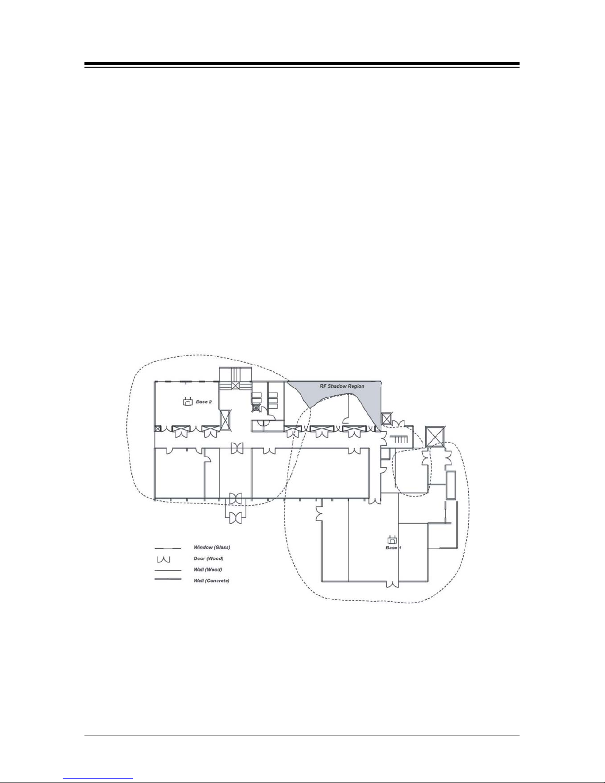
In a typical office environment, the radios of the cell supported by a Base Station is
approximately 25-40 meters. These figures however, are truly dependent on the office
characteristics (ex., construction material of walls, placement of metallic objects, doors,
windows, etc.); make sure to get to know the broadcast range in your environment
taking each office characteristic into account (refer to Figure 3.2.2-3).
Figure 3.2.2-3 Sampl e T emporary Base Station Positio n
3. Mark the position of the offices where wireless handsets (450H/480H/500H) mainly will
be used, and mark the places where high call demands would exist; these areas should
be well covered by the Base Stations.
4. Roughly determine the number of Base Stations and the positions needed according to
the above tips.
Page 14
iPECS eMG80
System DECT Installation Guide Issue 1.3
9
3.2.3 General Procedure for CRS
After getting well-acquainted with the operation of GDC-600TBE, and how the Base Stations
work as applicable to your facility, the CRS can be conducted. Section 3.2.2, Preliminary
Positions of Base Stations should already have been completed.
To conduct a CRS:
1. First, verify that other DECT Base Stations in the area are powered OFF; only the one
you are working with currently should be ON.
2. Enter the same PARK ID in GDC-600TBE and GDC-450H/480H/500H.
3. Mount GDC-600TBE at the determined temporary position as high as possible; it is
recommended to place GDC-600TBE at higher than 2 meters.
4. Check the Received Signal Strength Indicator (RSSI) level in GDC-450H/480H/500H by
walking around the area; decide the cell-coverage range temporarily using the predetermined RSSI level.
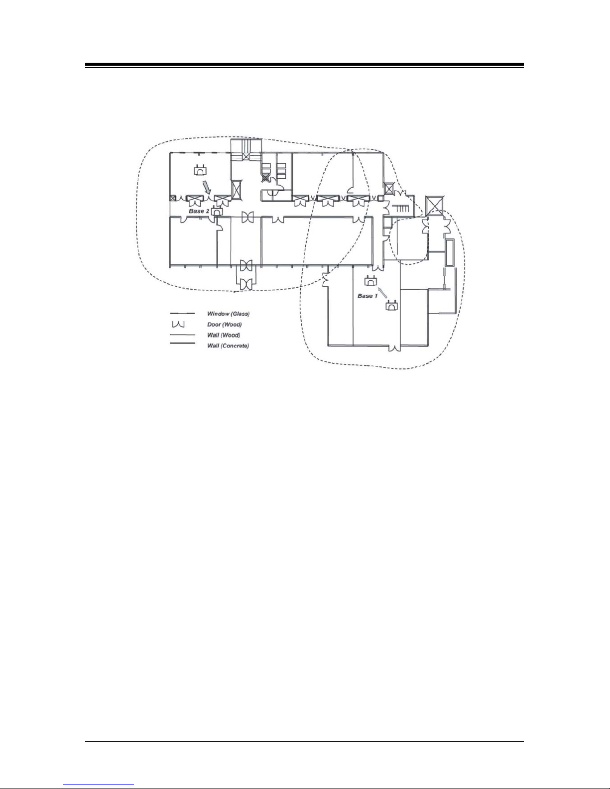
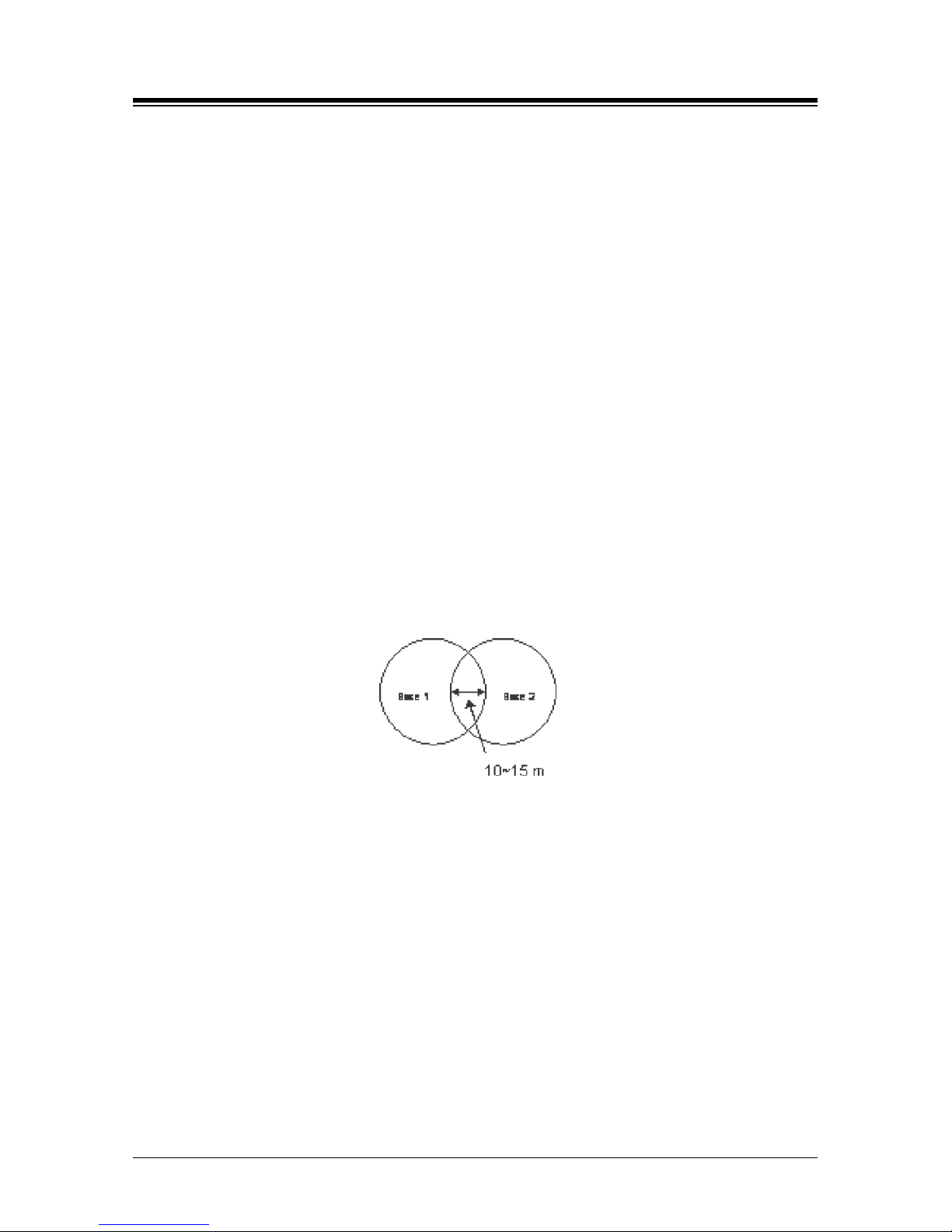
5. Repeat CRS procedure from Step 1 at the next tentative Base Station position; it is
likely and recommended that the cell-coverage will overlap a bit as shown:
Figure 3.2.3-1 Cell Bou ndary Map w i th Bas e 1 and Bas e 2
Page 15
iPECS eMG80
System DECT Installation Guide Issue 1.3
10
6. If marked positions on the drawing need to be adjusted, move Base Station positions by
checking shadow area on plan drawing, and adjusting the Cell-Coverage Regions
(consider traffic of 6 calls per area, and add to plan) as shown:
Figure 3.2.3-2 Adjusting Cell Boundary Positions for Base 1 and Base 2
7. After completing the CRS, install the Base Stations (GDC-600BE) in the optimal
locations.
8. Finalize the Base Station position by performing a handover and call test with wireless
terminals (ex., 450H/480H/500H), by checking the cell coverage region with GDC450H/480H/500H monitor RSSI level (recommended -65 ± 5dBm, walk with 2 handsets
and monitor for voice quality).
3.2.3.1 Additional Tips for CRS
The following lists what you should keep in mind during the CRS Test:
Draw a cell-coverage region map for each Base Station temporary position.
The height of a mounted Base Stati o n hi ghl y affects th e performance of Base Sta ti on ;
it is recommended Radio Fixed Parts (RFP) such as Base Stations, should be
mounted as high as possible, and at least higher than 2 meters.
It is good to locate the position of the RFP in order to secure as many line-of-sight
paths as possible, no obstacles be tw e en the RFP an d Ha nds et ( PP) , an d the path is
direct; a line-of-sight path is a good travel way for Radio Frequency signal.
All other DECT products should be powered-OFF, and GDC-600TBEs cannot work
simultaneously.
Testing during daytime in the real environment is more recommended, as the RSSI is
very sensitive to environmental situations; testing at night when the interfering factors
Page 16
iPECS eMG80
System DECT Installation Guide Issue 1.3
11
are minimized will bring quite different results from a real office environment.
If there is fading due to metal material, the RSSI value can be varied over a wide
range.
Use a fully-charged batt ery pack.
3.2.4 Base Station General Guidelines
Using the guidelines and examples below, determine and indicate the approximate Base station
locations on the drawing.
Maximize line-of-sight
Distance in open field 150 meters ~ -65 dbm
Distance in-office 25 to 40 meters
Distance in hallw ay or open factor y flo or 40 to 70 m eter s
Locate Base stations to minimize obstructions (sprinklers, exit signs, etc.)
Locate Base stations away from noise emitters (FAX machines, etc.)
Locate Base stations away from metal objects (tall fili ng c abinets, s ecur i ty/fire doors,
etc.)
Locate Base stations near the center of the desired coverage area
For proper handover, the coverage area of each Base station should overlap by 10 to
15 meters.
Consider high traffic areas such as conference rooms and cafeterias.
Each Base station supports four (4) simultaneous conversations.
Multiple Base stations can be co-located with a minimum distance of 0.25 meters.
For a multi-floor installation, plan coverage for each floor separately
Attenuation appr oximations considering office equipment and materials:
Open field = 0.5 db/meter
Office environment = 2 to 3 db/meter (25 ~ 40 meters)
Hall or open factory floor = 1 to 2 db/meter (40 to 70 meters)
Concrete and masonry = 15 db/cm
Windows, clear glass = 5 dbWindows, mirrored glass = 15 db
Drywall, standard = 5 db
Drywall, metal backed = 12 db
Metal, 1.5 mm = > 20db
Page 17
iPECS eMG80
System DECT Installation Guide Issue 1.3
12
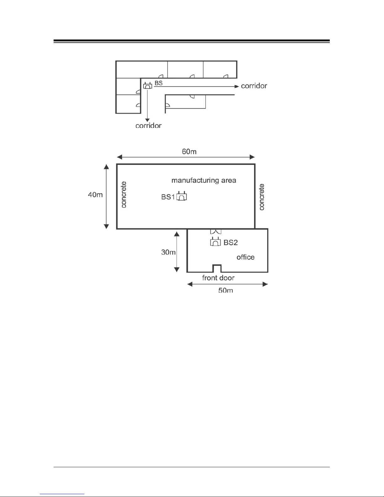
Figure 3.2.4-1 Hal l way Placement
Figure 3.2.4-2 Centralized Base Station Placement
Page 18
iPECS eMG80
System DECT Installation Guide Issue 1.3
13
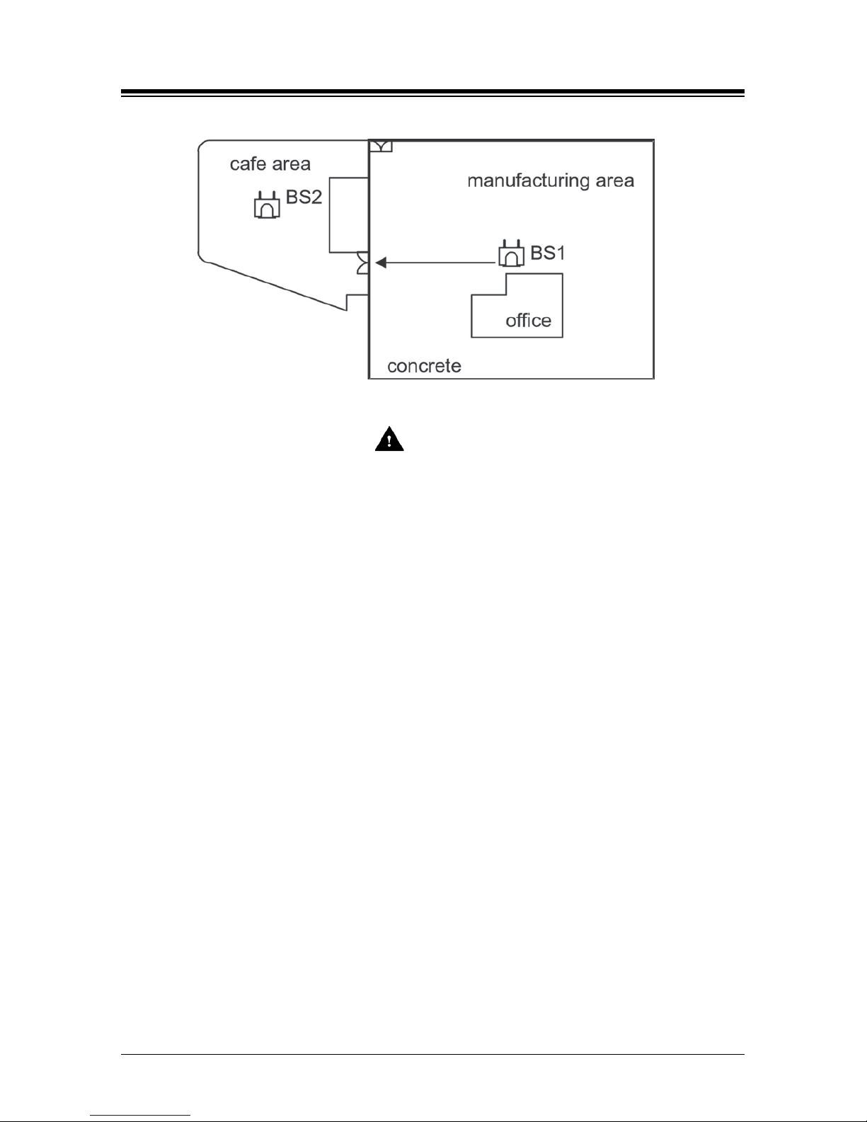
Figure 3.2.4-3 Base Station Aligned with Corridor to Adjoining Area
CAUTION
1. The appropriate position for a Base Station is no closer than 1.8m above the floor
and 0.5m below the ceiling.
- The best c om m unication environment is w h en a Base St ati o n a nd a us er are of
the same height. In an office environment, however, it is recommended to
consider off ic e furniture (especia lly iron desktops or cabinets) to minimize
reflection, diffraction and scatteri ng of DECT wave when you set the po sition o f a
Base Station.
2. Keep away from any electroni c equi pment such as copy machines, printers or
computers.
3. The lower wall of a corridor where many people pass by, corner of a wall, and
narrow indoors also should be avoided.
4. When you insta ll a Base Station on the wall, it is better to include intervals.
- DECT wave is attenuated by reflection indoors. In order to minimize attenuation,
when you install a Base Station on the wall, give at least three-wave-length
intervals. The intervals should be about 45cm because the wavelength is 15cm at
DECT frequency.
In iPECS eMG80 System, WTIB4 is Base Station interface board. iPECS eMG80 System can
have one WTIB4 (up to 4 ports).
Page 19
iPECS eMG80
System DECT Installation Guide Issue 1.3
14
3.3 WTIB4
The WTIB4 can be installed on KSU.
CAUTION
1. Pr ior to installing the WTIB4, System power should be turned OFF to avoid any
damage.
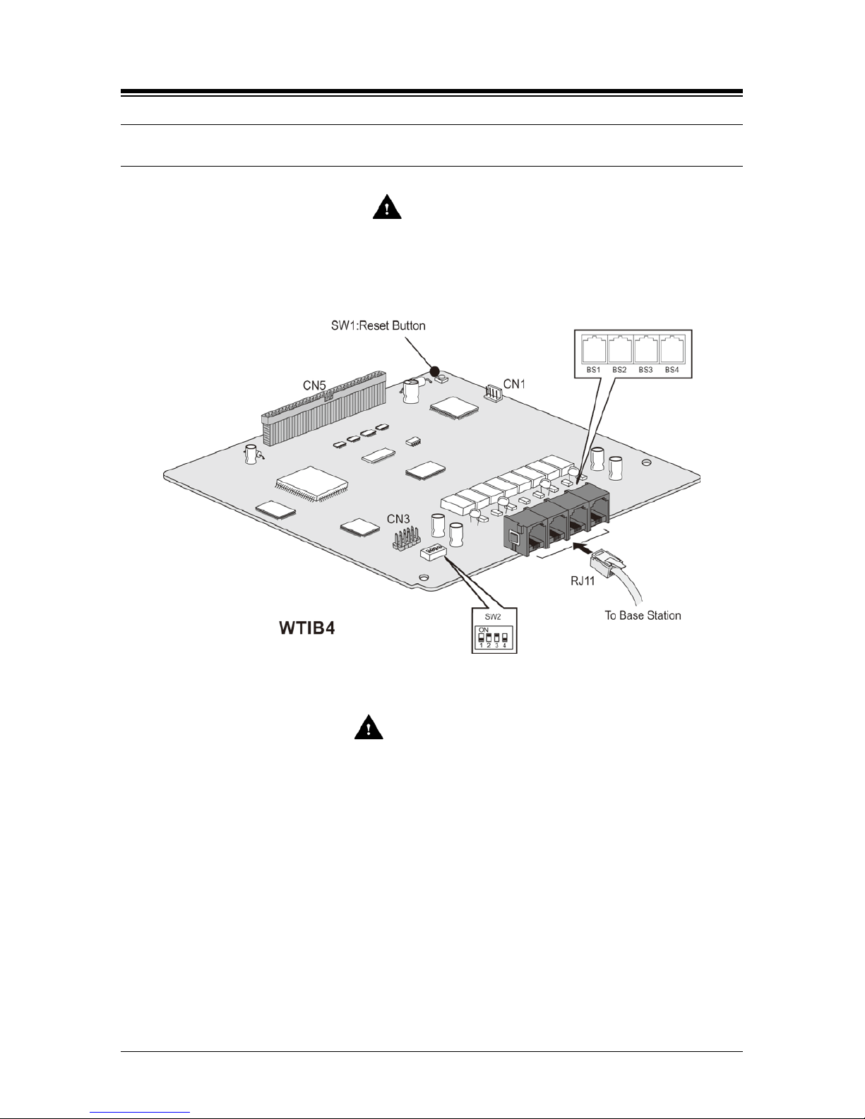
The layout and dip switch setting of WTIB4 of iPECS eMG80 is shown:
Figure 3.3-1 WTIB4
CAUTION
The Base Station is connected to the WTIB4 by an unshielded twisted pair cable (at least
CAT3).
NOTE
The unshielded twisted pair cable (at least CAT3) should be used to conn ect WTIB4
with a Base Station.
Shielded cable can be used if it can withstand interference from noise sources such
as an AC power cable with high voltage. A shorter cable length and/or clear line-ofview between the WTIB4 and Base Station will decrease the possibility of data
degradation.
Even though there are connection points such as MDF or the connection tab between
WTIB4 and Base Station, the connection points should be connected with twisted-pair
cable (at least CAT3). For example, WTIB4 to MDF, MDF to MDF, MDF to connection
tab, and connection tab to Base Station should be joined using twisted-pair cable.
Page 20
iPECS eMG80
System DECT Installation Guide Issue 1.3
15
3.3.1 Pi n Ass i gnment
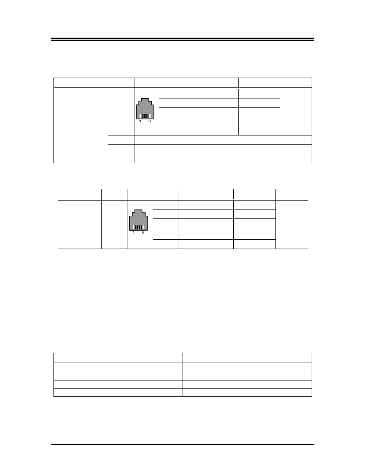
Table 3.3.1-1 WTIB 4
Connector Label PIN number Signal name Function Note
RJ11
WTI1
1, 6 Unused/reserved
Cell1
2 RX+(GND) Receive Data
3 TX-(+30V) Transmit Data
4 TX+(+30V) Transmit Data
5 RX-(GND) Receive Data
WTI2 The same as the above contents Cell2
WTI3 The same as the above contents Cell3
WTI4 The same as the above contents Cell4
Table 3.3.1-2 Base Stat ion
Connector Label PIN number Signal name Function Note
RJ11 MJ1
1, 6 Unused/reserved
2 TX+(GND) T ransmit Data
3 RX(+30V)
Receive Data
4 RX(+30V)
Receive Data
5
TX-(GND)
Transmit Data
NOTE
Using unshielded twisted-pair cable (more than CAT3), wire the Base Station RJ-11 to
the termin ati on point/MDF for connection to a WTIB 4.
Tag or number wiring for maintenance.
3.3.2 Connectors, Switch and LED Functions
The following table shows the relation between modular connector and associated cell numbers.
Table 3.3.2-1 Connector Functions
Connector CELL Number
MJ1-1(WTIB4)
Cell 1
MJ1-2(WTIB4) Cell 2
MJ1-3(WTIB4)
Cell 3
MJ1-4(WTIB4) Cell 4
The 4 LEDs mounted on iPECS eMG80 WTIB4 provide diagnostic information for status of the
board. The following table shows the meaning of the different LED status indicators
Page 21

iPECS eMG80
System DECT Installation Guide Issue 1.3
16
Table 3.3.2-2 Switch Functions
SW1
Switch
Function
Remark
SW1
Reset Button
Static swit ch
SW2 - DIP Switch
Pole
Functions
ON
OFF
Default
1
Operation
TBR6 mode
Normal se rvice mode
OFF
2
Echo canceller Control
Echo canceller on
Echo canceller off
ON
3
Reserved
Reserved
Reserved
ON
4 Registration mode
Registration
Management OFF
Registration
Management ON
OFF
NOTE
TBR6 test mode needs not t o be set for norm al operation because TBR6 test mode is
used only for DECT confirmation test.
Table 3.3.2-3 LED Indications
LED
Color
Description
LD1
Blue
HDLC Interrupt
LD2
Blue
Working indication (400ms period)
LD3
Blue
BASE Message Interrupt
LD4 Blue
On: Echo canceller enable
Off: Ech o canc eller disable
Page 22
iPECS eMG80
System DECT Installation Guide Issue 1.3
17
3.4 Description and Installation of GDC-600BE
3.4.1 GDC-600E Description
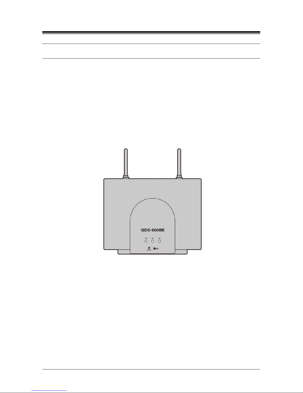
GDC-600BE Base station employs DECT technology to provide an RF link to any standard DECT
GAP handset such as GDC-450H/480H/500H. The Base Station connects to a WTIB4 for access
to features and resources of iPECS with an RJ-11 4-wire connector on the left-side of the unit. In
addition to providing the path for signaling and audio between the Base Station and the WTIB4,
this connection provides power to GDC-600BE.
Two antennas provide antenna diversity to minimize the effects of RF signal reflection. The Base
Station is meant for indoor wall mounting only. The Base Station is directly mounted on the wall
using two (2) screws.
Figure 3.4.1 GDC-600BE DECT Base Station
3.4.2 Base Station Installation
As mentioned in previous sections in this chapter, before permanently mounting a Base Station,
you should determine the most appropriate location for providing the best coverage. Base
Stations may be mounted on wall or desktop up to 600m away from the WTIB4 using a twisted 2pair unshielded cable (0.5φ, AWG 24). They are remotely powered (DC 30 volts) by the WTIB4.
The number of Base Stations used in a system depends on the area to be covered and the traffic
density. The typical in-house coverage is a 75m radius for GDC-600BE. In practice, the cell
outdoor radius in free space may up to 400m for GDC-600BE.
There are two ways to install the Base Station: mounting directly to wall surface, or mounting
usi n g a w edge, as described in the following Section.
Page 23
iPECS eMG80
System DECT Installation Guide Issue 1.3
18
3.4.2.1 Mounting Base Station
The weight of a Base Station is approximately 460g (1.2lb.), so it can be mounted on a masonry
or dry-wall surface, wooden wall, or partition wall.
Before mounting Base Station permanently, you should determine locations that provide the best
coverage (refer to General Procedure for CRS). To wall mount the Base Station, perform the
following Steps:
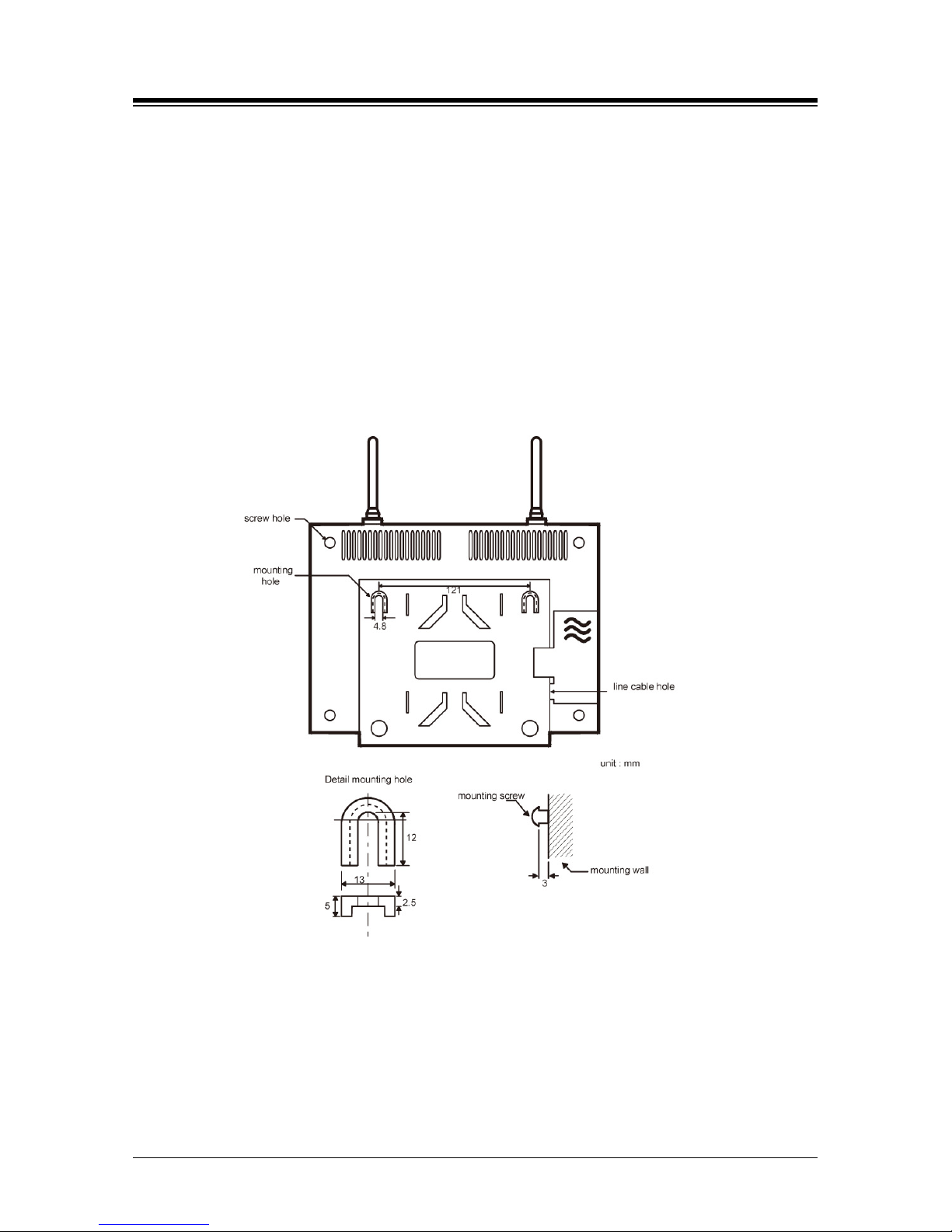
1. Drill two 3.5mm holes in a fixed wall; to properly position the holes, use the mounting
template (last sheet of this manual) and copy it if necessary. The distance between
mounting holes is 121mm as shown in the image.
2. Insert anchors into the drilled holes.
3. Insert screws in the anchors, leaving a 3mm gap between the wall and screw head.
4. Mount the Base Station eyelets on the screws.
Figure 3.4.2.1 Back side of GDC-600BE
Before mounting base station permanently, you should determine locations that provide the best
coverage. The wall mounting procedure of a base station is as follows:
1. Drill two 3.5mm holes in a fixed wa ll. To properly position the holes, you can use mounting
template that is the last sheet of this manual and copy it if necessary.
2. Insert anchors into the drilled holes. Then insert scre ws in the anchors, leaving a 3mm gap
between the wall and screw head.
3. Mount the base station eyelets on the screws.
Page 24
iPECS eMG80
System DECT Installation Guide Issue 1.3
19
3.4.2.2 Mounting Base St ation - 2 (Using Wedge)
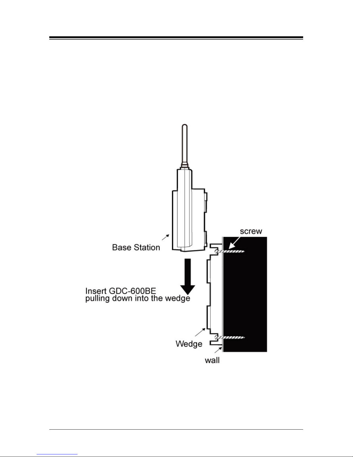
To Install the Base Station using the wedge:
1. First determine the appropriate location on wall where the wedge will be mounted.
2. The wedge should be affixed to the wall using two screws; use the mounting template
as in #1 of the previous procedure.
3. Attach the Base Station to the wedge by aligning the guides to the back the Base
Station and pulling the Base Station down until it is secure on the wedge.
Figure 3.4.2.2 Side of GDC-600BE
Page 25

iPECS eMG80
System DECT Installation Guide Issue 1.3
20
3.4.2.3 LED Indications
Table 3.4.2.3-1 GDC-600BE
LED Description
S1
RED : booting status or communication error
AMBER :
- Steady ON : image downloading mode
- Blinking : normal operation + all 6 channels used
GREEN :
- Stea d y ON : n or mal operation ( idle)
- Blinking : normal operation + up to 5 channels used
S2
RED : Booting status or E1 Sync. error
AMBER : E1 loopback mode or downloading mode
GREEN :
- S teady ON : Sync. OK
- Blinking : Synchronizing
S3
RED : FPGA function error
AMBER :
- Blinking : downloading mode
GREEN :
- Blinking : E1 Tx/Rx operation indication
3.4.2.4 Traffic Guidelines
Each GDC-600BE Base Station supports 6 simultaneous calls, but because all users are not
usual ly simultaneously on calls, a Base Station can support a greater number of wireless terminal
users in practice.
Table 3.4.2.4-1 GDC-600BE
Number of CELL
(Base Station)
Number of Wireless Terminal
Max. Number of simultaneous
conversation
1
Up to 48
6
2
12 3 18 4 24
Page 26
iPECS eMG80
System DECT Installation Guide Issue 1.3
21
3.5 Ferrite Core Installation and Wiring
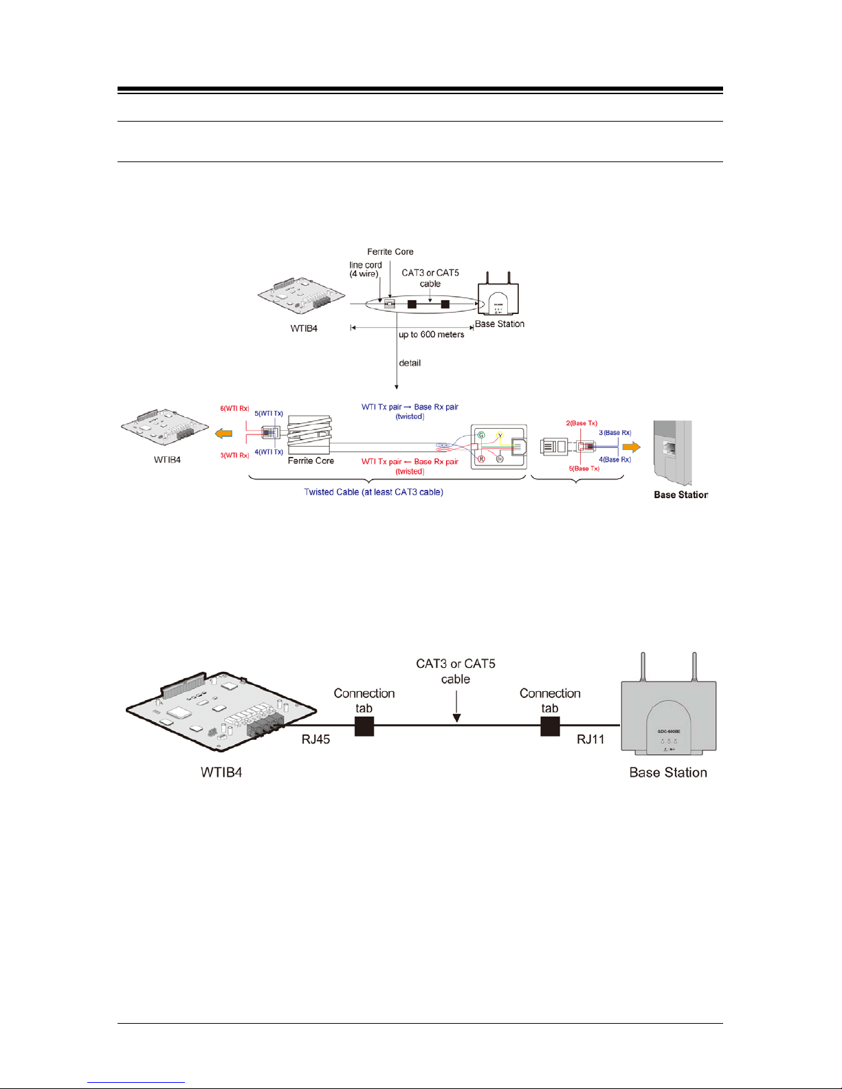
Ferrite core is provided in the packaging of the Base Station for EMI. The Ferrite core should be
installed when the WTIB4 is installed in the system. One Ferrite core is to be used with the line
cord between the Base Station and each port of WTIB4 (as shown).
Figure 3.5-1 Cable connection with Ferrite Core between WTIB4 and Base Station
Figure 3.5-2 Wiring wi th connection tab between WTIB4 and Base Station
CAT5 cable is provided by Ericsson-LG
Enterprise, twisted 2-pair or CAT3 cable
Page 27
iPECS eMG80
System DECT Installation Guide Issue 1.3
22
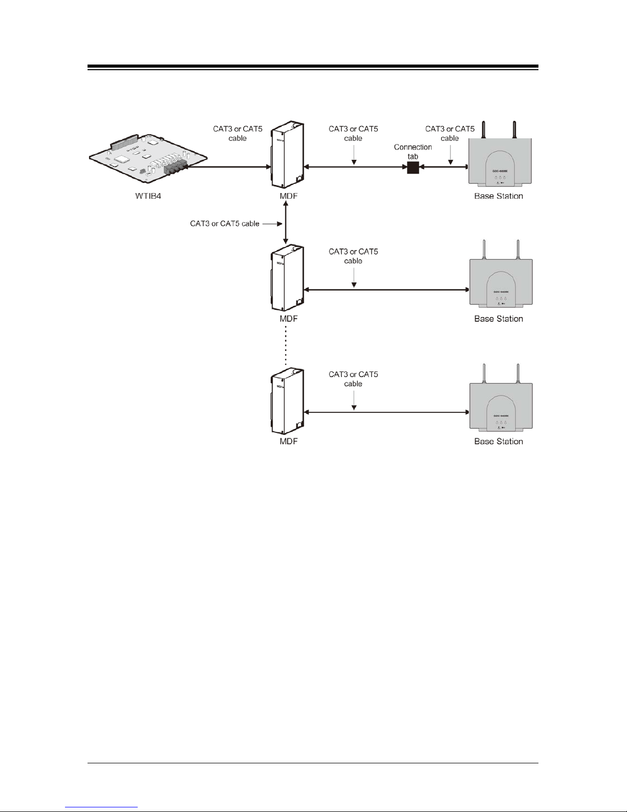
Figure 3.5-3 Wiring wi th MD F and conn e cti o n tab betwe en WTIB4 and Bas e St ation
NOTE
Even though there are connection points such as MDF or connection tab between
WTIB4 and Base Station, the connection points should be connected with twisted-pair
cable (at least CAT3 class) each other. For example, WTIB4 to MDF, MDF to MDF,
MDF to connection tab, and connection tab to Base Station should be connected with
twisted-pair cable
Page 28

iPECS eMG80
System DECT Installation Guide Issue 1.3
23
3.6 User Subscription/Unsubscription
3.6.1 System ID
A System ID is given to iPECS eMG80 system attached to the wireless terminal for identification.
System ID, which is the Potable Access Rights Key (PARK), is written on the KSU.
The Authentication Code as well as System ID should be entered at only the Attendant Station
before subscribing the wireless terminal to iPECS eMG80 system.
To display the System ID, perform the following Steps:
1. From the Attendant station, press [TRANS/PGM] button.
2. Dial 0#.
3. Press the FLEX 4 button.
When modifying or entering the System ID:
1. From the Attendant Station, press [TRANS/PGM] button.
2. Dial 0#.
3. Press the FLEX 6 button.
4. Enter the System ID (PARK code, refer to key sequence description below).
5. When finished, press the [HOLD/SAVE] button; a confirmation tone will be heard.
CAUTION
Normally you should not change the system ID. If you should change it, please
contact Ericsson-LG E nterprise or the local dealer in your country.
The key sequence of the PARK= LLP__________PC
LL – Two digits decimal representation of PARK length (Bit count)
P______P – 11 heximal di gi ts re pr esentati o n o f P AR K
C – Check digit, calculated as the sum of each digit in the input stream multiplied by
its position in the input stream, module of 11; if the result is 10, this is represented by *.
Conditions
1. The System ID must be programmed when the System is installed.
2. When System ID is programmed, all previously entered data related to wireless features
will be erased.
3. The initial PARK value is 00000000000000; the value will display in LCD at first.
Page 29

iPECS eMG80
System DECT Installation Guide Issue 1.3
24
3.6.2 Aut hentication Code
The Authentication Code is entered at the Attendant station before subscribing a User wireless
terminal to iPECS eMG80.
To display the Authentication Code, perform the following Steps:
1. From the Attendant station, press [TRANS/PGM] button.
2. Press 0#.
3. Press th e FLEX 3 button; the current AC code will display on the LCD.
4. If Authentication code is correct, exit the program mode.
1. From the Attendant station, press [TRANS/PGM] button.
If Authentication code is wrong, please follow the procedure:
2. Press 0#.
Press th e FLEX 3 button; the current AC code will display on the LCD.
3. Enter the Authentication Code (up to 8 digits, refer to key sequence description below).
4. When finished, press [HOLD/SAVE]; a confirmation tone will be heard.
The key sequence of the AC code= D______D
D_______D – Up to 8 digits decimal representation.
Condition
1. AC code must be programmed for User Subscription.
2. AC code must be programmed after the system was installed; if AC code is changed
while under system operation, it may not operate properly (ex., subscribed terminal may
not receive incoming calls or not make an outgoing call).
3. If PARK value is changed, AC code must also be entered again.
4. The initial AC code is 000000.
5. AC code change will not affect the system operation except subscribing new wireless
terminals.
Page 30

iPECS eMG80
System DECT Installation Guide Issue 1.3
25
3.6.3 User Subscription
This procedure is for subscribing the wireless terminal to iPECS eMG80 system.
To subscribe the wireless terminal to iPECS eMG80 system at Attendant Station:
1. From the Attendant station, press [TRANS/PGM] button.
2. Dial 0#.
3. Press the FLEX 1 button.
4. Enter the appropriate Station Number.
5. Enter the phone type ( 2=Standard GAP, 3=GDC-40x/45xH, 5=GDC-480H/500H)
6. Press th e [HOLD/SAVE] button; a confirmation tone is heard.
7. The Attendant Station LCD should display “SUBSCRIBED: SUCCESS”; if message is
not received, perform Steps again from #1.
To subscribe at the wireless terminal (e.g. GDC-480H/500H):
1. Press [MENU] button.
2. Select [Phone Register] menu.
3. Select [Subscription] menu.
4. Select the empty base number (1-4) using [UP/DOWN] button, and press [OK] button.
5. The wireless terminal will search for the register system and ‘SEARCHING...X’ is
displayed on the LCD. After searching the register system, PARK value is displayed on
the LCD.
- If value displayed is correct, press [OK] button; confirmation tone will be heard and
displayed at the Attendant Station and at the wireless terminal which will then return to
an idle state displaying the appropriate station number.
- If value is not correct, press the [NO] button; the terminal will retry the search and
display ‘SEARCHING…X” on the LCD.
6. Enter AC code (up to 8 digits decimal representation) and press [OK] button.
7. If search fails, repeat the above steps at the Attendant Station and Wireless Terminal.
Condition
1. Wireless terminal must be subscr ibe d t o sys t em for normal ser vice.
2. Only Attendant can subscribe the wireless terminals (GAP).
3. Attendant can subscribe another wireless terminal after one subscribing procedure.
4. An error tone will be heard if attendant attempts to subscribe a wireless terminal that
was subscribed already.
Page 31

iPECS eMG80
System DECT Installation Guide Issue 1.3
26
3.6.4 User Unsubscription I
This procedure will di s connect a w i reless ter minal from th e iPECS eMG80 system. To
unsubscribe a wireless terminal, it should be in an idle state.
To unsubscribe a wireless terminal from the Attendant Station, perform the following:
1. At the Attendant station, press [TRANS/PGM] button.
2. Dial 0#.
3. Press the FLEX2 button.
4. Enter the appropriate Station Number.
5. Press [HOLD/SAVE] button; a confirmation tone will be heard and displayed to the
Attendant station and the Wireless terminal.
- If using GDC-480H/500H, It will attempt to synchronize the next registered system; if
any available system doesn’t exist, GDC-480H/500H displays “Not Subscribed” on LCD.
6. Power-Off the wireless terminal.
Condition
1. Only an Attendant can unsubscribe a wireless terminal.
2. Attendant can only unsubscribe wireless terminals that were subscribed already; if
attendant attempts to unsubscribe an unsubscribed wireless terminal, an error tone will
be heard.
3. Attendant can unsubscribe another wireless terminal after completing an unsubscribing
procedure.
4. Attendant can perform unsubscribing procedure only when the wireless terminal is in an
idle state.
Page 32

iPECS eMG80
System DECT Installation Guide Issue 1.3
27
3.6.5 User Unsubscription II
If you want to perform the unsubscription procedure at wireless terminal and Attendant station
independently, follow the procedure described below.
To erase all subscriptions from Attendant Station:
1. At the Attendant station, press [TRANS/PGM] button.
2. Dial 0#.
3. Press the FLEX 7 button.
4. Enter the appropriate password (147*).
5. Press th e [HOLD/SAVE] button; a confirmation tone will be heard.
To erase one subscription from Attendant Station:
1. From the wireless terminal, press the [TRANS/PGM] button.
2. Dial 0#.
3. Press the FLEX8 button.
4. Enter the appropriate Station Number.
5. Press the [HOLD/SAVE] button; a confirmation tone will be heard.
Condition
1. Wireless terminal must be unsubscribed from the system for normal service.
2. Only an Attendant can unsubscribe a wireless terminal.
3. Attendant can unsubscribe another wireless terminal after completing the subscribing
procedure; if attendant attempts to unsubscribe an unsubscribed wireless terminal, an
error tone will be heard.
Page 33

iPECS eMG80
System DECT Installation Guide Issue 1.3
28
3.6.6 RSSI Monitoring
Received Signal Strength Indicator (RSSI) Monitoring is a way that the dealer can install Base
Stations without using the CRS tool. The RSSI level of a Base Station to which the wireless
terminal is locked is displayed as a “dBm" value on the LCD (up to 80dbm.); the value is updated
periodically. The handset must be subscribed for this function to work.
To use RSSI Monitoring when using a GDC-480H/GDC-500H wireless terminal:
1. From the wireless terminal.
2. Press th e [Menu] button.
3. Press th e * key.
4. Enter the Technician menu by entering press PIN code (L G G A P = 5 4 4 2 7).
5. Press [OK] button.
6. Select the [CELL TOOL] mode to YES and press the [OK] button.
7. The RSSI value will display on LCD of wireless terminal (automatically updated
periodically).
Page 34

iPECS eMG80
System DECT Installation Guide Issue 1.3
29
4. ATTENDANT SERVICES
The Attendant can manage User subscriptions to iPECS eMG 80 DECT. The Attendant enables
subscriptions, can unsubscribe User data, request authentication and register a User to another
networked system. In addition, the Attendant can view and modify DECT-related codes
(Authentication and PARK). It is recommended these codes not be changed as subscribed
handsets may perform erratically. Subscription management and code control services are
available under the Attendant DECT Data program.
To access the DECT Data program from the Attendant station, perform the following procedure:
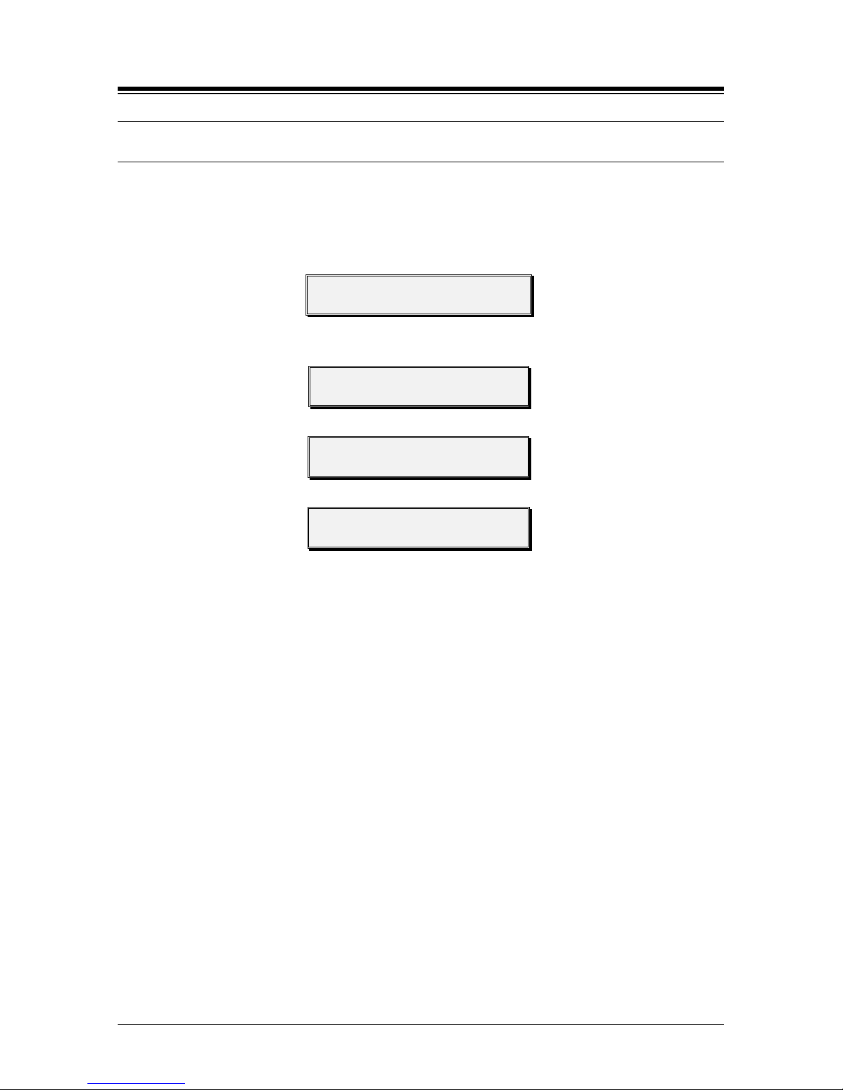
1. Press th e [PGM] button.
STATION 100 (T)
04 SEP 01 02:49 PM
2. Dial 0 and #.
3. Press the desired Flex button (1-9),
WTU (UN) SUBSCRIBE
PRESS FLEX BUTTON
Flex Button 1 – Enter the station number for subscription => 4.1 Enable Subscripti on
Flex Button 2 – Enter the station number for un-subscription => 4.2 Terminate a
Subscription
Flex Button 3 – Enter Authentication Code for Wireless ter minal => 4.3 Authe nti cation
Code for DECT subscription
Flex Button 4 – View the system ID (PARK Code) =>4.4 Viewing System ID (PARK
code)
Flex Button 5 – Enter Authentication Code for Desk terminal => 4.5 Authenticating a
user
Flex Button 6 – Modify the system ID (PARK Code) => 4.6 Modifying the system ID
(PARK code)
Flex Button 7 – Delete all subscriber data => 4.7 Deleting all subscripti ons
Flex Button 8 – Delete each subscriber da ta => 4.8 Deleting a single subscription
Flex Button 9 – DECT zone Mobility => 4.9 Registering to Networked systems
Page 35
iPECS eMG80
System DECT Installation Guide Issue 1.3
30
4.1 Enable Subscription
For security and control, handset subscription must be authorized, and enabled. Once enabled,
the User can subscribe the DECT handset.
To enable a subscription from the Attendant, perform the following procedure:
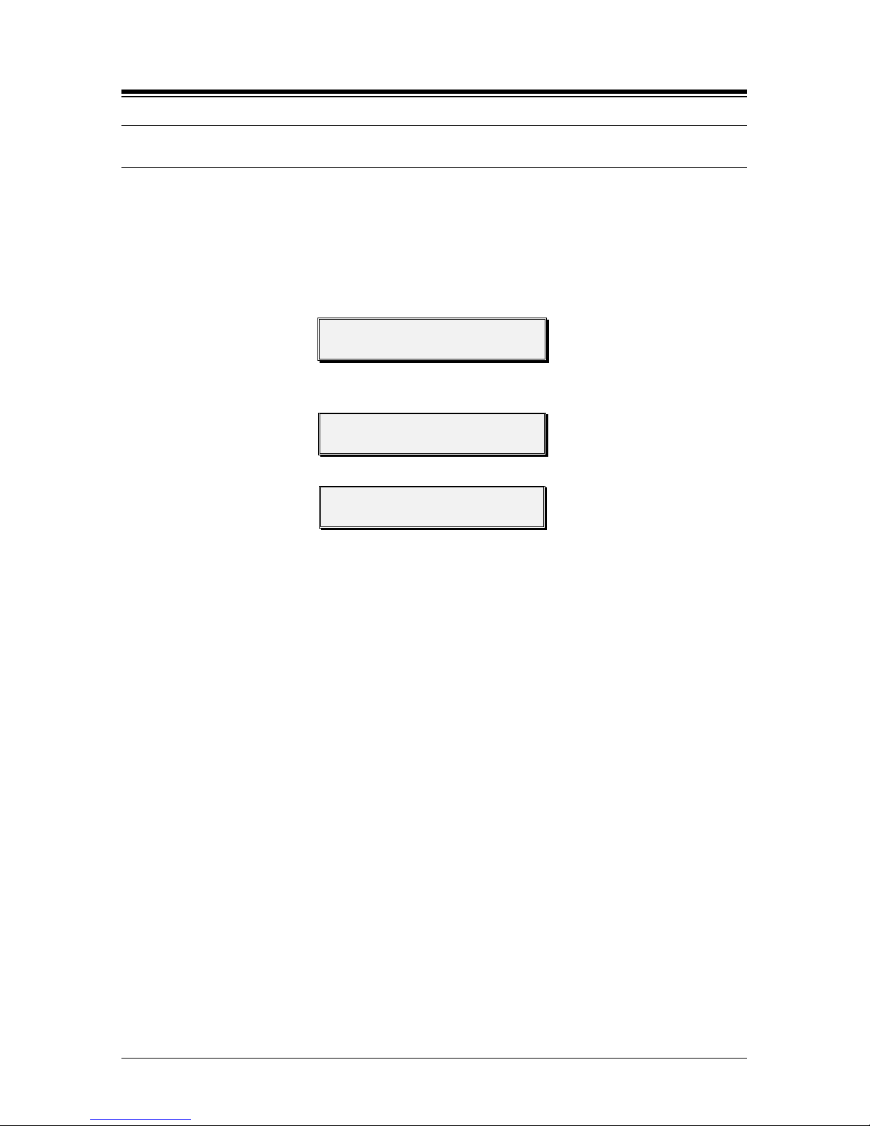
1. Press the [PGM] button.
STATION 100 (T)
04 SEP 01 02:49 PM
2. Dial 0 and #.
3. Press Flex button 1.
WTU (UN) SUBSCRIBE
PRESS FLEX BUTTON
4. Enter the Station number of the subscribing Station.
WTU SUBSCRIBE ENABLE
ENTER STA NO.
5. Enter the Type of Handset,
STATION : XXX
ENTER PHONE TYPE
2 – Standard DECT GAP
3 – GDC-400H/450H
5 – GDC-480H/500H
6. Press [HOLD/SAVE] button and await Success message.
7. Press Speaker to return to idle.
Page 36
iPECS eMG80
System DECT Installation Guide Issue 1.3
31
4.2 Terminate a Subscription
For security and control, a subscription only can be terminated by the Attendant. Once the
subscription is terminated, the wireless handset will no longer have access to iPECS services and
will display an unregistered or not subscribed status. The handset must be idle to terminate the
subscription.
To terminate a subscription from the Attendant, perform the following procedure:
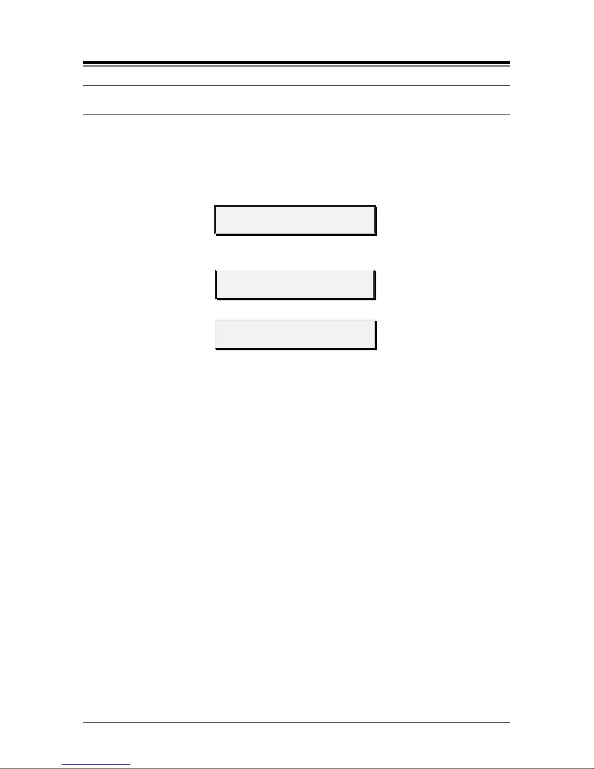
1. Press the [PGM] button.
STATION 100 (T)
04 SEP 01 02:49 PM
2. Dial 0 and #.
3. Press Flex button 2.
WTU (UN)SUBSCRIBE
PRESS FLEX BUTTON
4. Enter the Station number of the subscribing Station.
WTU UNSUBSCRIBE
ENTER STA NO.
5. Press [HOLD/SAVE] and await confirmation tone.
6. Press Speaker to return to idle.
Page 37
iPECS eMG80
System DECT Installation Guide Issue 1.3
32
4.3 Authentication Code for DECT Subscription
When a user subscribes to iPECS eMG80 DECT, entry of the DECT Authentication code is
required. The Authentication Code entered by the User is compared to the code in the system
to ver i fy the User subscription.
To view or enter the Authentication code from the Attendant, perform the following procedure:
1. Press the [PGM] button.
STATION 100 (T)
04 SEP 01 02:49 PM
2. Dial 0 and #.
3. Press Flex button 3.
WTU (UN)SUBSCRIBE
PRESS FLEX BUTTON
4. Enter the new Authentication Code (up to 8 digits).
AC CODE: XXXXXXXX
ENTER DGT & HOLD BTN
5. Press [HOLD/SAVE] button and await confirmation tone.
6. Press Speaker to return to idle.
NOTE
The Authentication Code must be assigned before a user can subscribe for ser vi ce s.
Changing the Authentication Code after handsets have registered will cause
improper operation, handsets may display erratic operation and may not be able to
subscrib e or de-subscribe. If the Authentication Code must be changed, first unsubscribe all handsets, see section 4.7.
If the system Id is changed, the Authentication Code must be reassigned.
Page 38
iPECS eMG80
System DECT Installation Guide Issue 1.3
33
4.4 Viewing the System ID (PARK code)
The system Id, also known as the PARK (Portable Access Rights Key) code, is used to identify
the DECT system. During subscription, the user can verify the handset is subscribing to the
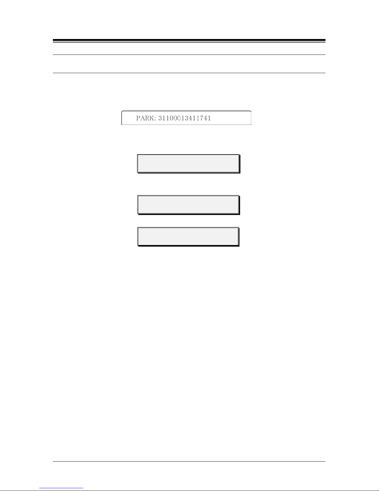
correct DECT system. Each WTIB carries a label with the PARK code as shown in the example.
In a cascade of WTIBs, the PARK code of the master WTIB is used for the system.
To view the Id for the iPECS eMG80 DECT from the Attendant station, follow the procedure
below.
1. Press the [PGM] button.
STATION 100 (T)
04 SEP 01 02:49 PM
2. Dial 0 and #.
3. Press Flex button 4.
WTU (UN)SUBSCRIBE
PRESS FLEX BUTTON
4. The current System ID (PARK code) displays.
PARK: xxxxxxxxxxxxxx
5. Press [HOLD/SAVE] button.
6. Press Speaker to return to idle.
Page 39
iPECS eMG80
System DECT Installation Guide Issue 1.3
34
4.5 Authenticating a User
The Attendant can request a User verify their identification. The Attendant requests an
authentication, and in response the handset displays a request for the user to enter their Personal
ID Number (PIN). The use r must enter their PIN in order to receive further services from System
DECT.
The PIN, which may be up to five (5) digits is assigned in the handset by the user (refer to the
GDC-480H/GDC-500H User Guide).
1. Press the [PGM] button.
STATION 100 (T)
04 SEP 01 02:49 PM
2. Dial 0 and #.
3. Press Flex button 5.
WTU (UN)SUBSCRIBE
PRESS FLEX BUTTON
4. Enter the desired Station number.
WTU USER AUTHENTICATE
ENTER STA NO.
5. Press [HOLD/SAVE], and await Pass/Fail display on the Attendant phone LCD along
with confirmation tone.
6. Press Speaker to return to idle.
Page 40
iPECS eMG80
System DECT Installation Guide Issue 1.3
35
4.6 Modifying the System ID (PARK code)
The System ID (PARK code) is a 14-digit number, which uniquely identifies the DECT system.
Each DECT System must have a unique PARK code. Should a conflict occur between an iPECS
eMG80 DECT and another DECT system, the System ID can be changed.
NOTE
Changing the System ID of an operational i PEC S eMG80 DECT will remove all
subscription and Authentication Code data. It will be necessary to enter an
Authentication Code and subscribe all wireless handsets to System DECT if the
System ID is changed.
To modify System ID from the Attendant, perform the following procedure:
1. Press the [PGM] button.
STATION 100 (T)
04 SEP 01 02:49 PM
2. Dial 0 and #.
3. Press Flex button 6.
WTU (UN)SUBSCRIBE
PRESS FLEX BUTTON
4. The current System ID (PARK code) displays; enter the new PARK code.
PARK: xxxxxxxxxxxxxx
5. Press [HOLD/SAVE] button.
6. Press Speaker to return to idle.
Page 41
iPECS eMG80
System DECT Installation Guide Issue 1.3
36
4.7 Deleting all Subscriptions
DECT handsets can be subscribed to an iPECS eMG80 DECT. In some situations, subscription
data can be deleted from System DECT when moving a DECT Base station or iPECS. In this
case, existing subscriptions are deleted and all handset subscriptions must be re-initialized for
obtaining access to System DECT services:
1. Press the [PGM] button.
STATION 100 (T)
04 SEP 01 02:49 PM
2. Dial 0 and #.
3. Press Flex button 7.
WTU (UN)SUBSCRIBE
PRESS FLEX BUTTON
4. Enter 147* (password).
WTU SUBS ALL DATA ERASE
PRESS PASSWD & HOLD
5. Press [HOLD/SAVE] button.
6. Press Speaker to return to idle.
Page 42
iPECS eMG80
System DECT Installation Guide Issue 1.3
37
4.8 Deleting a Single Subscription
DECT handsets can be subscribed to an iPECS eMG80 DECT. In some situations, subscription
data for a handset can be deleted from System DECT when replacing a handset. When the
subscription is deleted, the handset must be re-initialized for access to System DECT services:
1. Press the [PGM] button.
STATION 100 (T)
04 SEP 01 02:49 PM
2. Dial 0 and #.
3. Press Flex button 8.
WTU (UN)SUBSCRIBE
PRESS FLEX BUTTON
4. Enter desired Station number.
WTU SUBSCRIPTION ERASE
ENTER STA NO.
5. Press [HOLD/SAVE] button.
6. Press Speaker to return to idle.
Page 43
iPECS eMG80
System DECT Installation Guide Issue 1.3
38
4.9 Registering to a Networked System
GDC handset can be subscribed to the System DECT of several iPECS eMG80s simultaneously.
If the iPECS eMG80s are part of a network, the DECT handset can be assigned DECT Mobility
and have calls to one iPECS routed over the network to the DECT handset location. To register a
handset for DECT Mobility from the Attendant station, follow the procedure:
1. Press the [PGM] button.
STATION 100 (T)
04 SEP 01 02:49 PM
2. Dial 0 and #.
3. Press Flex button 9.
WTU (UN)SUBSCRIBE
PRESS FLEX BUTTON
4. Enter desired Station number.
DECT MOBILITY
ENTER STA NO.
5. Enter 1 to enable Network Mobility.
STATION: XXX
(1:ON/0:OFF): ?? ?
6. Press [HOLD/SAVE] button.
7. Press Speaker to return to idle.
Page 44

iPECS eMG80
System DECT Installation Guide Issue 1.3
39
5. TROUBLESHOOTING
PROBLEM CAUSE/SYMPTOM SOLUTION
User cannot place a call usi ng
DECT handset
WTIB4 issue
- Please chec k a t least one DEC T
base st
ation is proper ly conn ec te d
to WTIB4.
DECT Handset issue
- Please chec k the DECT termina l
is regist ered and subscr iption is
completed.
- Please check the DECT terminal
user is located in the RF coverage
area of the DECT base station.
DECT frequen tly drops calls Base Station issue
- Please chec k ce ll-planning of
DECT base stations.
- Please check the DECT terminal
user is located in the RF coverage
of DE CT base stations.
- Please check all WTIBs are
installed on the same KSU when
multiple WTIBs are used together.
Page 45

iPECS eMG80
System DECT Installation Guide Issue 1.3
40
Thanks for purchasing iPECS eMG80
The contents of this document are subject to revision
without notice due t o continued progre ss in methodolog y,
design and manufacturing. Ericsson-LG Ent erpri se shall
have no liability for any error or damage of any kind
resulting from the use of this document.
 Loading...