

Page 1
IPCorder KNR-412 Installation manual
September 28, 2008
Page 2

2
Page 3
Contents
1 Installation 5
1.1 Package contents . . . . . . . . . . . . . . . . . . . . . . . . . . . . . . . . . . . . . . . . . 5
1.2 Disk installation . . . . . . . . . . . . . . . . . . . . . . . . . . . . . . . . . . . . . . . . . 6
1.3 IPCorder connection . . . . . . . . . . . . . . . . . . . . . . . . . . . . . . . . . . . . . . . 6
1.3.1 Connecting . . . . . . . . . . . . . . . . . . . . . . . . . . . . . . . . . . . . . . . . 6
1.3.2 Accessing the IPCorder over network . . . . . . . . . . . . . . . . . . . . . . . . . . 7
1.4 Storage settings . . . . . . . . . . . . . . . . . . . . . . . . . . . . . . . . . . . . . . . . . . 7
2 LED indicators and buttons of the device 9
2.1 Device states and their indication . . . . . . . . . . . . . . . . . . . . . . . . . . . . . . . . 9
2.2 Controlling the device using the buttons . . . . . . . . . . . . . . . . . . . . . . . . . . . . 9
3 Upgrading the rmware 11
4 Factory reset 13
5 Troubleshooting in Rescue Mode 15
6 Exchanging disc 17
3
Page 4

4
CONTENTS
Page 5
Chapter 1
Installation
1.1 Package contents
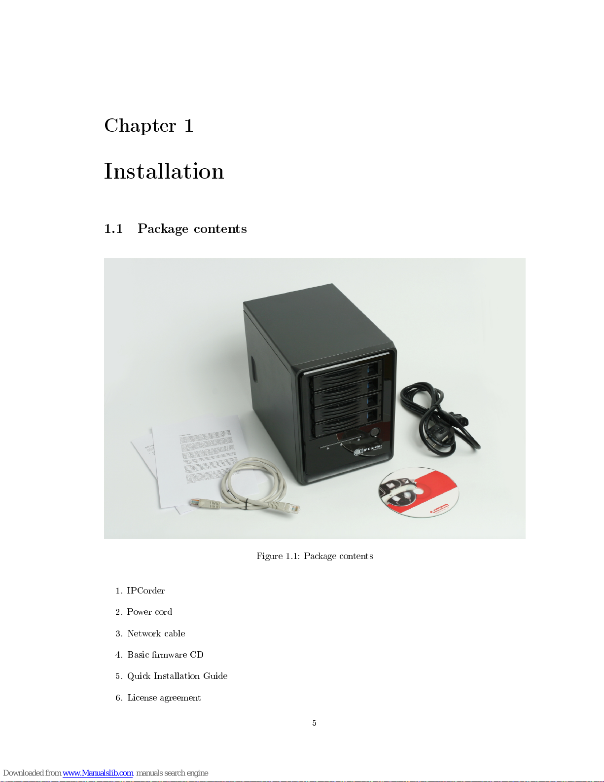
Figure 1.1: Package contents
1. IPCorder
2. Power cord
3. Network cable
4. Basic rmware CD
5. Quick Installation Guide
6. License agreement
5
Page 6
6
CHAPTER 1. INSTALLATION
1.2 Disk installation
It is possible to connect up to six SATA or SATA 2 disks (disk types can be combined) to IPCorder, four
internal and two external.
Each of internal disks must be inserted into one of the llers at the front of the device. Use this
procedure for installation a disk into the ller:
1. remove the ller
2. remove the cover
3. insert the disk and secure it with screws
4. insert the ller back into the device
External disks are to be connected to IPCorder using eSATA interface. Proper connectors marked
eSATA 1 and eSATA 2 are on the back side of the device. External disks must have its own power
source.
Do not remove already installed disks without rst correctly removing them from the system (see Section
1.4).
1.3 IPCorder connection
1.3.1 Connecting
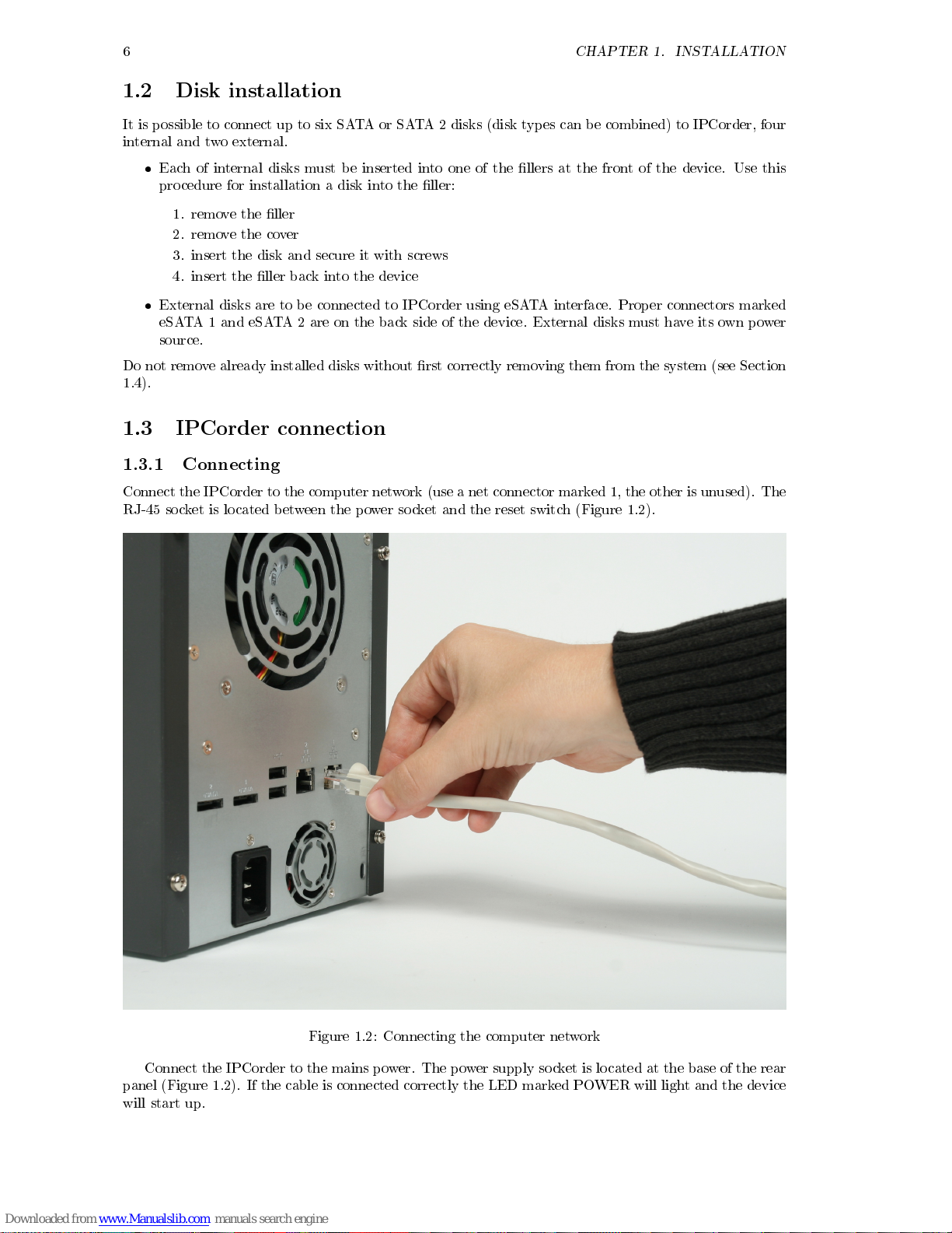
Connect the IPCorder to the computer network (use a net connector marked 1, the other is unused). The
RJ-45 socket is located between the power socket and the reset switch (Figure 1.2).
Figure 1.2: Connecting the computer network
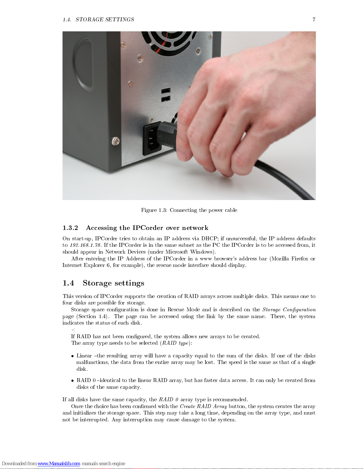
Connect the IPCorder to the mains power. The power supply socket is located at the base of the rear
panel (Figure 1.2). If the cable is connected correctly the LED marked POWER will light and the device
will start up.
Page 7
1.4. STORAGE SETTINGS
7
Figure 1.3: Connecting the power cable
1.3.2 Accessing the IPCorder over network
On start-up, IPCorder tries to obtain an IP address via DHCP; if unsuccessful, the IP address defaults
to
192.168.1.78
. If the IPCorder is in the same subnet as the PC the IPCorder is to be accessed from, it
should appear in Network Devices (under Microsoft Windows).
After entering the IP Address of the IPCorder in a www browser's address bar (Mozilla Firefox or
Internet Explorer 6, for example), the rescue mode interface should display.
1.4 Storage settings
This version of IPCorder supports the creation of RAID arrays across multiple disks. This means one to
four disks are possible for storage.
Storage space conguration is done in Rescue Mode and is described on the
Storage Conguration
page (Section 1.4).The page can be accessed using the link by the same name. There, the system
indicates the status of each disk.
<
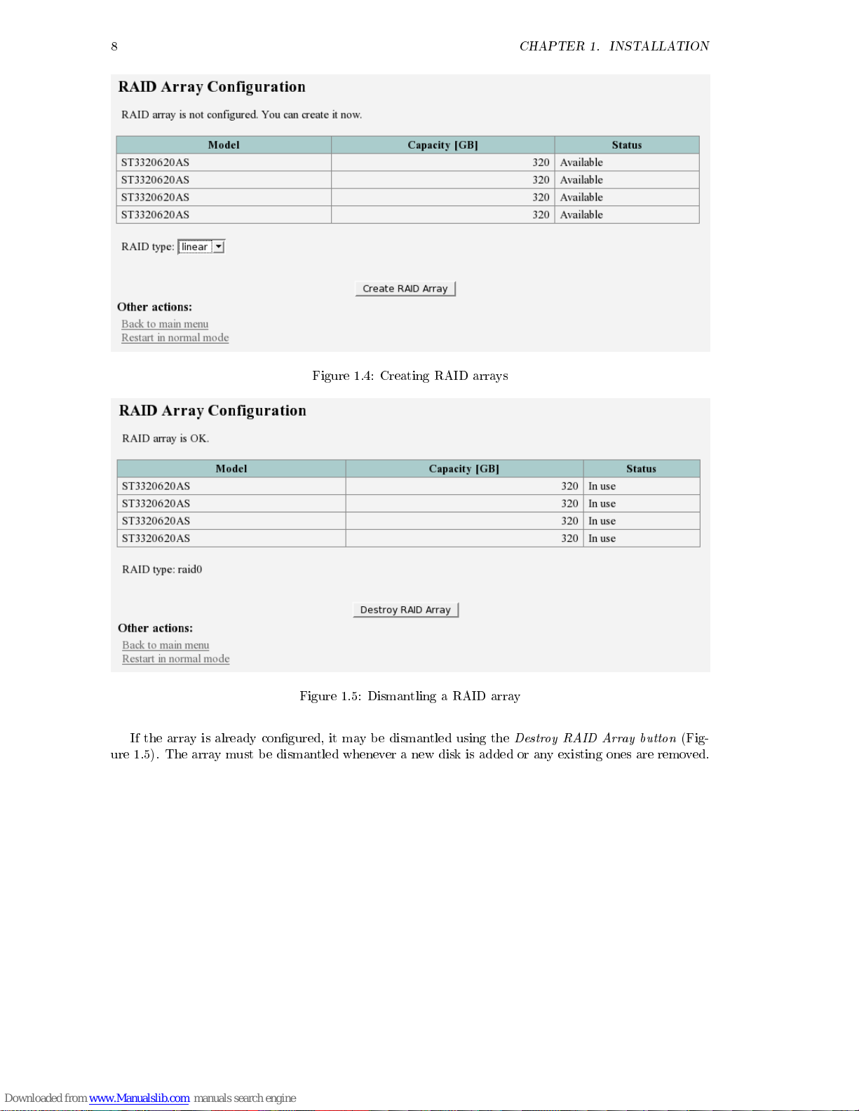
If RAID has not been congured, the system allows new arrays to be created.
The array type needs to be selected (
RAID type
):
Linear the resulting array will have a capacity equal to the sum of the disks. If one of the disks
malfunctions, the data from the entire array may be lost. The speed is the same as that of a single
disk.
RAID 0 identical to the linear RAID array, but has faster data access. It can only be created from
disks of the same capacity.
If all disks have the same capacity, the
RAID 0
array type is recommended.
Once the choice has been conrmed with the
Create RAID Array
button, the system creates the array
and initializes the storage space. This step may take a long time, depending on the array type, and must
not be interrupted. Any interruption may cause damage to the system.
Page 8
8
CHAPTER 1. INSTALLATION
Figure 1.4: Creating RAID arrays
Figure 1.5: Dismantling a RAID array
If the array is already congured, it may be dismantled using the
Destroy RAID Array button
(Fig-
ure 1.5). The array must be dismantled whenever a new disk is added or any existing ones are removed.
Page 9
Chapter 2
LED indicators and buttons of the
device
2.1 Device states and their indication
The Power LED always lights up in blue, which indicates the device is on.
The device may further indicate one of the following statuses:
Normal mode the System LED lights orange
Start the System LED ashes green
Shut down the System LED is simultaneously lit in orange and ashes green
Rescue Mode the System LED is lit in orange, and the individual disk LEDs ash red in sequence
from top to bottom
2.2 Controlling the device using the buttons
The device has two control buttons; the Power button is located on the front panel, and the Reset button
is in a small hole on the rear panel.
When the Power button is pressed and released, the device goes to Shut Down, after which it
restarts.
When the Power button is pressed and held for 2 seconds, the device shuts down. When this is
complete, the device may be safely disconnected from the mains supply.
When the Reset button is pressed in Normal Mode, the device goes to Shut Down, and subsequently
restarts in Rescue Mode.
Similarly, by pressing the Reset button in Rescue Mode, the device reverts back to Normal Mode.
9
Page 10

10
CHAPTER 2. LED INDICATORS AND BUTTONS OF THE DEVICE
Page 11
Chapter 3
Upgrading the rmware
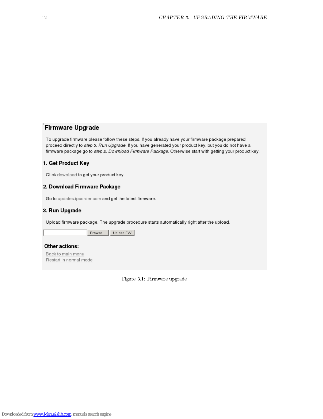
1. Upgrading the rmware is always done with a
device key
. A key should be downloaded from every
device. Downloading a device key is described in the
User Manual
.
2. The rmware upgrade package is always unique for each device. Each device should therefore
be registered under your account at
http://updates.ipcorder.com
. If you do not have an account
at
http://updates.ipcorder.com
, navigate to this address without delay and follow the on-screen
instructions for creating a new account.
3. A
rmware package
can be generated for a given device by following the instructions on the server
at
http://updates.ipcorder.com
.
4. Firmware upgrades are carried out in
Rescue Mode
. Switching to
Rescue Mode
is described in the
User Manual
.
5. Once in
Rescue Mode
go to the
Firmware Upgrade
page.
6. The generated
rmware package
should be entered in step
3. Run Upgrade
. When the
Upload FW
button
is pressed the upgrade will begin.
7. The upgrade must not be interrupted; any interruption may damage the device. When the upgrade
is complete the system will give a notication.
8. To switch back to normal mode, click the
Restart in normal mode
link.
11
Page 12
12
CHAPTER 3. UPGRADING THE FIRMWARE
Figure 3.1: Firmware upgrade
Page 13
Chapter 4
Factory reset
A factory reset may be required, for example, if the device becomes damaged, or before a re-sale. This
function erases all stored data on the disks and returns the settings to their default state.
The process must not be interrupted, otherwise permanent damage to the device may be caused.
Verify in advance that the device's power source is stable, and do not turn the device o until the process
is complete.
Warning:
data on magnetic media (hard disk) cannot ever be entirely removed. If the disk contained
sensitive data, which should not be passed into the hands of any third party, we recommend not reselling
the disks, but rather having them physically destroyed.
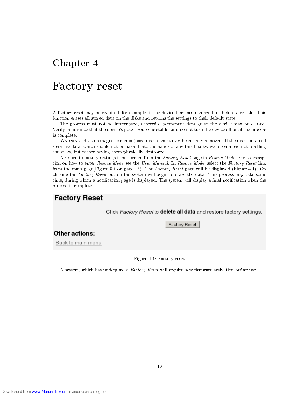
A return to factory settings is performed from the
Factory Reset
page in
Rescue Mode
. For a descrip-
tion on how to enter
Rescue Mode
see the
User Manual
. In
Rescue Mode
, select the
Factory Reset
link
from the main page(Figure 5.1 on page 15). The
Factory Reset
page will be displayed (Figure 4.1). On
clicking the
Factory Reset
button the system will begin to erase the data. This process may take some
time, during which a notication page is displayed. The system will display a nal notication when the
process is complete.
Figure 4.1: Factory reset
A system, which has undergone a
Factory Reset
will require new rmware activation before use.
13
Page 14

14
CHAPTER 4. FACTORY RESET
Page 15
Chapter 5
Troubleshooting in Rescue Mode
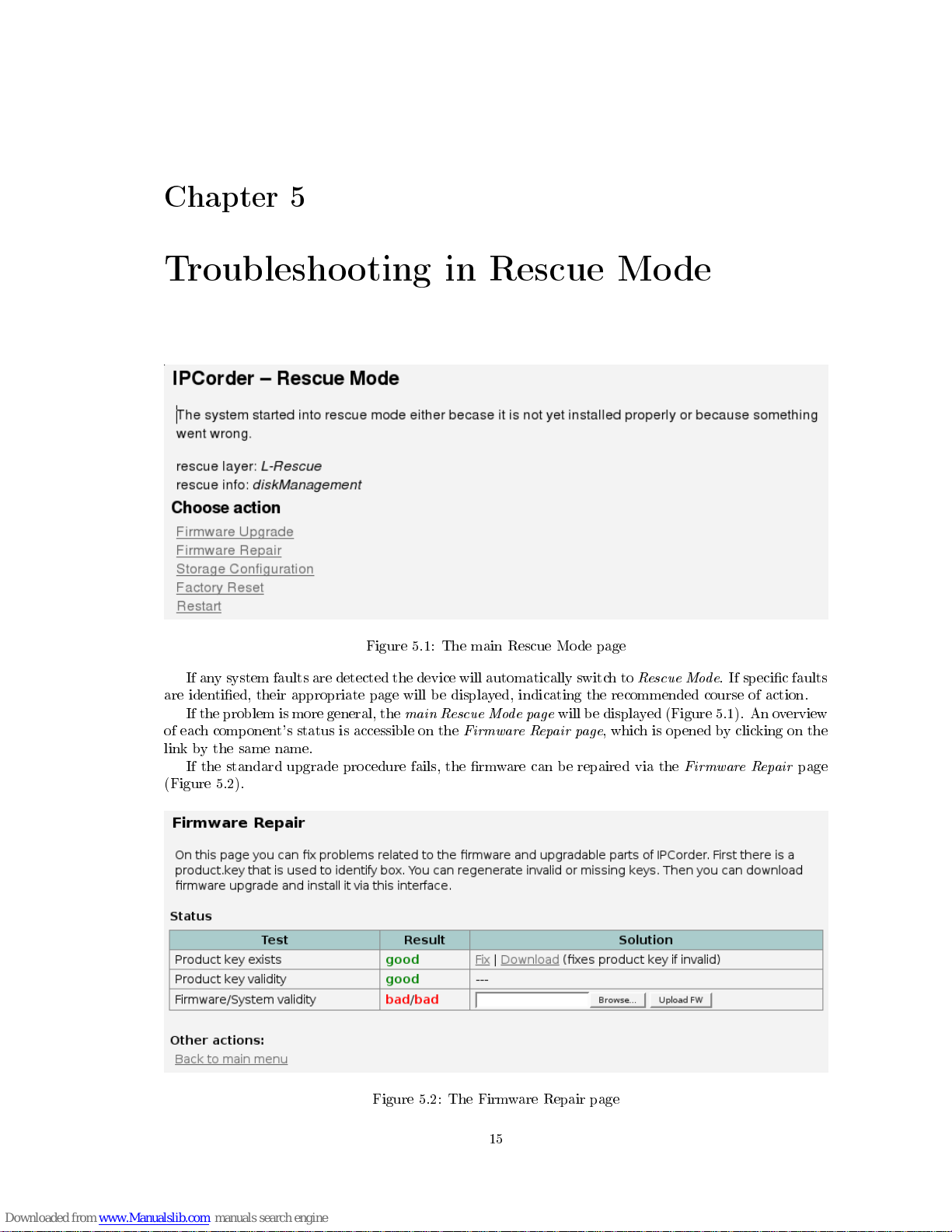
Figure 5.1: The main Rescue Mode page
If any system faults are detected the device will automatically switch to
Rescue Mode
. If specic faults
are identied, their appropriate page will be displayed, indicating the recommended course of action.
If the problem is more general, the
main Rescue Mode page
will be displayed (Figure 5.1). An overview
of each component's status is accessible on the
Firmware Repair page
, which is opened by clicking on the
link by the same name.
If the standard upgrade procedure fails, the rmware can be repaired via the
Firmware Repair
page
(Figure 5.2).
Figure 5.2: The Firmware Repair page
15
Page 16

16
CHAPTER 5. TROUBLESHOOTING IN RESCUE MODE
Page 17
Chapter 6
Exchanging disc
If a disc is broken or lled, for exchanging the disc please follow the instructions:
switch to Rescue mode and destroy RAID array using the button in Storage conguration page
turn the device o a, remove the disc and add a new one like in Disc installation Section 1.2
after turning the device on the RAID array has to be created again
the others congurations will be preserved, the only data, that will be removed, are camera records
17
Page 18

18
CHAPTER 6. EXCHANGING DISC
Page 19
List of Figures
1.1 Package contents . . . . . . . . . . . . . . . . . . . . . . . . . . . . . . . . . . . . . . . . . 5
1.2 Connecting the computer network . . . . . . . . . . . . . . . . . . . . . . . . . . . . . . . 6
1.3 Connecting the power cable . . . . . . . . . . . . . . . . . . . . . . . . . . . . . . . . . . . 7
1.4 Creating RAID arrays . . . . . . . . . . . . . . . . . . . . . . . . . . . . . . . . . . . . . . 8
1.5 Dismantling a RAID array . . . . . . . . . . . . . . . . . . . . . . . . . . . . . . . . . . . . 8
3.1 Firmware upgrade . . . . . . . . . . . . . . . . . . . . . . . . . . . . . . . . . . . . . . . . 12
4.1 Factory reset . . . . . . . . . . . . . . . . . . . . . . . . . . . . . . . . . . . . . . . . . . . 13
5.1 The main Rescue Mode page . . . . . . . . . . . . . . . . . . . . . . . . . . . . . . . . . . 15
5.2 The Firmware Repair page . . . . . . . . . . . . . . . . . . . . . . . . . . . . . . . . . . . 15
19
 Loading...