

Page 1

Page 2

Copyright statement
Copyright © 2016 IP-COM Networks Co., Ltd. All rights reserved.
IP-COM is the registered trademark of IP-COM Networks Co., Ltd. Other brand and product names mentioned
herein are trademarks or registered trademarks of their respective holders. Copyright of the whole product as
integration, including its accessories and software, belongs to IP-COM Networks Co., Ltd. No part of this
publication can be reproduced, transmitted, transcribed, stored in a retrieval system, or translated into any
language in any form or by any means without the prior written permission of IP-COM Networks Co., Ltd.
Disclaimer
Pictures, images and product specifications herein are for references only. To improve internal design, operational
function, and/or reliability, IP-COM reserves the right to make changes to the products described in this document
without obligation to notify any person or organization of such revisions or changes. IP-COM does not assume any
liability that may occur due to the use or application of the product or circuit layout(s) described herein. Every
effort has been made in the preparation of this document to ensure accuracy of the contents, but all statements,
information and recommendations in this document do not constitute a warranty of any kind, express or implied.
- i -
Page 3

Item
Presentation
Example
Menu
Bold
System indicates the "System" menu.
Cascading menus
>
Choose System > Live Users.
Item
Meaning
Note
This format is used to highlight information of importance or special interest. Ignoring this
type of note may result in ineffective configurations, loss of data or damage to device.
Tip
This format is used to highlight a procedure that will save time or resources.
Preface
Thank you for purchasing IP-COM Multi-WAN Hotspot Router! This user manual helps you configure, manage and
maintain the product.
Conventions
This user manual is applicable to IP-COM Multi-WAN Hotspot Router M50.
Unless otherwise specified, “router”, "this router", “product”, or “device” mentioned in this user manual
indicates M50.
Typographical conventions in this user manual:
Symbols in this user manual:
For more documents
Go to our website at http://www.ip-com.com.cn and search for the latest documents for this product.
- ii -
Page 4

Tel: (86 755) 2765 3089
E-mail: info@ip-com.com.cn
Website: http://www.ip-com.com.cn
Search for
documents here.
Technical support
If you need more help, contact us using any of the following means. We will be glad to assist you as soon as
possible.
- iii -
Page 5

Table of contents
Chapter 1 Product overview ....................................................................................... 2
1.1 Overview ..................................................................................................................................................................... 2
1.2 Main features.............................................................................................................................................................. 2
1.3 Appearance ................................................................................................................................................................. 3
1.3.1 Front panel .......................................................................................................................................................... 3
1.3.2 Rear panel ............................................................................................................................................................ 4
Chapter 2 Quick internet connection setup ................................................................ 5
2.1 Logging in to the router web UI .................................................................................................................................. 5
2.2 Configuring the router ................................................................................................................................................ 6
2.2.1 PPPoE ................................................................................................................................................................... 7
2.2.2 Dynamic IP address ............................................................................................................................................. 8
2.2.3 Static IP address ................................................................................................................................................... 9
Chapter 3 Login ........................................................................................................ 11
3.1 Logging in to the router web UI ................................................................................................................................ 11
3.2 Logging out of the router web UI ............................................................................................................................. 11
3.3 Web UI layout ........................................................................................................................................................... 11
3.4 Common buttons on the web UI .............................................................................................................................. 12
Chapter 4 Network ................................................................................................... 13
4.1 Setting up an internet connection ............................................................................................................................ 13
4.2 Setting WAN port parameters .................................................................................................................................. 15
4.2.1 WAN speed ........................................................................................................................................................ 15
4.2.2 MTU ................................................................................................................................................................... 15
4.2.3 MAC address ...................................................................................................................................................... 16
4.3 Setting up your LAN .................................................................................................................................................. 17
4.3.1 LAN port IP addresses ........................................................................................................................................ 18
4.3.2 DHCP server ....................................................................................................................................................... 18
- iv -
Page 6

4.3.3 Static IP addresses assignment using DHCP ...................................................................................................... 19
4.3.4 DHCP Client List ................................................................................................................................................. 21
4.4 Configuring port mirroring........................................................................................................................................ 22
4.4.1 Overview............................................................................................................................................................ 22
4.4.2 Configuring port mirroring ................................................................................................................................ 22
4.4.3 Port mirroring configuration example ............................................................................................................... 23
4.5 Configuring a static route ......................................................................................................................................... 24
4.5.1 Overview............................................................................................................................................................ 24
4.5.2 Configuring a static route .................................................................................................................................. 24
4.5.3 Static route configuration example ................................................................................................................... 26
4.6 Using the Hotel mode ............................................................................................................................................... 28
4.6.1 Overview............................................................................................................................................................ 28
4.6.2 Configuring the Hotel mode .............................................................................................................................. 29
4.7 Configuring the DNS cache ....................................................................................................................................... 29
4.7.1 Overview............................................................................................................................................................ 29
4.7.2 Configuring the DNS cache ................................................................................................................................ 29
Chapter 5 Filter management ................................................................................... 30
5.1 Overview ................................................................................................................................................................... 30
5.1.1 Function description .......................................................................................................................................... 30
5.1.2 Configuration instruction................................................................................................................................... 31
5.2 Setting IP address groups and time groups .............................................................................................................. 32
5.2.1 Setting time groups ........................................................................................................................................... 32
5.2.2 Setting IP address groups .................................................................................................................................. 34
5.3 Setting the MAC address filter .................................................................................................................................. 35
5.3.1 Setting the MAC address filter ........................................................................................................................... 35
5.3.2 Example of setting the MAC address filter ........................................................................................................ 38
5.4 Setting the port filter ................................................................................................................................................ 40
5.4.1 Setting the port filter ......................................................................................................................................... 40
5.4.2 Example of setting the port filter ...................................................................................................................... 42
5.5 Setting the web filter ................................................................................................................................................ 44
5.5.1 Setting the web filter ......................................................................................................................................... 45
5.5.2 Example of setting the web filter ...................................................................................................................... 48
5.6 Setting multi-WAN policies ....................................................................................................................................... 51
5.6.1 Customizing a multi-WAN policy ....................................................................................................................... 52
- v -
Page 7

5.6.2 Example of customizing a multi-WAN policy ..................................................................................................... 54
Chapter 6 Bandwidth control .................................................................................... 56
6.1 Overview ................................................................................................................................................................... 56
6.1.1 Function introduction ........................................................................................................................................ 56
6.1.2 Configuration instruction................................................................................................................................... 56
6.2 Setting bandwidth control ........................................................................................................................................ 57
6.2.1 Enabling user-defined bandwidth control ......................................................................................................... 57
6.2.2 Setting user-defined bandwidth control rules ................................................................................................... 58
6.2.3 Setting bandwidth control parameters for non-specified user devices ............................................................. 60
6.3 Example of setting user-defined bandwidth control ................................................................................................ 60
Chapter 7 VPN .......................................................................................................... 63
7.1 Overview ................................................................................................................................................................... 63
7.1.1 Network topology .............................................................................................................................................. 63
7.1.2 VPN types .......................................................................................................................................................... 63
7.1.3 IPSec-related concepts ...................................................................................................................................... 63
7.2 Configuring a VPN ..................................................................................................................................................... 64
7.2.1 Configuring M50 as a PPTP/L2TP client ............................................................................................................. 64
7.2.2 Configuring M50 as a PPTP/L2TP server ............................................................................................................ 66
7.2.3 Configuring the IPSec function .......................................................................................................................... 69
7.3 Example of configuring a VPN................................................................................................................................... 74
7.3.1 Example of configuring a PPTP/L2TP VPN ......................................................................................................... 74
7.3.2 Example of configuring an IPSec VPN ................................................................................................................ 79
Chapter 8 Security .................................................................................................... 83
8.1 Overview ................................................................................................................................................................... 83
8.2 Binding an IP address with a MAC address ............................................................................................................... 84
8.2.1 Enabling the IP-MAC binding function .............................................................................................................. 84
8.2.2 Configuring an IP-MAC binding entry ................................................................................................................ 85
8.3 Protecting against attacks ......................................................................................................................................... 86
Chapter 9 AC management ....................................................................................... 89
- vi -
Page 8

9.1 Overview ................................................................................................................................................................... 89
9.2 Configuring wireless settings .................................................................................................................................... 90
9.2.1 Enabling the AC management function ............................................................................................................. 90
9.2.2 Delivering wireless network policies to APs ...................................................................................................... 90
9.3 Configuring advanced settings .................................................................................................................................. 93
9.3.1 Configuring RF settings ...................................................................................................................................... 93
9.3.2 Configuring global settings ................................................................................................................................ 96
9.4 Managing APs ........................................................................................................................................................... 99
9.4.1 Exporting information about APs managed by the router ................................................................................ 99
9.4.2 Rebooting APs.................................................................................................................................................... 99
9.4.3 Upgrading APs ................................................................................................................................................. 100
9.4.4 Resetting APs ................................................................................................................................................... 100
9.4.5 Deleting APs ..................................................................................................................................................... 101
9.4.6 Updating AP information ................................................................................................................................. 101
9.4.7 Modifying AP configuration ............................................................................................................................. 101
9.5 Viewing user status ................................................................................................................................................. 102
9.5.1 Exporting user information.............................................................................................................................. 103
9.5.2 Disconnecting a user ....................................................................................................................................... 103
9.6 Updating user information ..................................................................................................................................... 104
Chapter 10 Captive portal ....................................................................................... 105
10.1 Overview ............................................................................................................................................................... 105
10.1.1 Function description ...................................................................................................................................... 105
10.1.2 Configuring web authentication .................................................................................................................... 105
10.2 Configuring web authentication ........................................................................................................................... 106
10.2.1 Configuring basic settings .............................................................................................................................. 106
10.2.2 Managing users ............................................................................................................................................. 109
10.3 Example of configuring web authentication ......................................................................................................... 110
Chapter 11 PPPoE authentication ........................................................................... 114
11.1 Overview ............................................................................................................................................................... 114
11.1.1 Function description ...................................................................................................................................... 114
11.1.2 Configuration instruction............................................................................................................................... 114
11.2 Configuring PPPoE authentication ........................................................................................................................ 114
- vii -
Page 9

11.2.1 Configuring basic settings .............................................................................................................................. 114
11.2.2 Managing accounts........................................................................................................................................ 118
11.3 Example of configuring PPPoE authentication ...................................................................................................... 120
Chapter 12 Virtual server ........................................................................................ 128
12.1 Overview ............................................................................................................................................................... 128
12.1.1 Port forwarding ............................................................................................................................................. 128
12.1.2 UPnP .............................................................................................................................................................. 128
12.1.3 DMZ host ....................................................................................................................................................... 128
12.1.4 DDNS ............................................................................................................................................................. 128
12.2 Port forwarding ..................................................................................................................................................... 129
12.2.1 Configuring port forwarding .......................................................................................................................... 129
12.2.2 Example of port forwarding ........................................................................................................................... 130
12.3 UPnP ..................................................................................................................................................................... 131
12.4 DMZ host .............................................................................................................................................................. 132
12.4.1 Configuring the DMZ host function ............................................................................................................... 132
12.4.2 Example of configuring the DMZ host function ............................................................................................. 132
12.5 DDNS ..................................................................................................................................................................... 134
12.5.1 Configuring the DDNS Function ..................................................................................................................... 134
12.5.2 Example of configuring the DDNS function ................................................................................................... 135
Chapter 13 Maintenance ........................................................................................ 138
13.1 Setting user names and passwords ...................................................................................................................... 138
13.2 Rebooting the router ............................................................................................................................................ 139
13.2.1 Rebooting the router manually ..................................................................................................................... 139
13.2.2 Rebooting the router regularly ...................................................................................................................... 139
13.3 Backing up and restoring configuration ................................................................................................................ 140
13.3.1 Backing up a configuration ............................................................................................................................ 140
13.3.2 Restoring a configuration .............................................................................................................................. 140
13.4 Upgrading the firmware ....................................................................................................................................... 141
13.5 Restoring the factory settings ............................................................................................................................... 141
13.5.1 Resetting the router through web UI ............................................................................................................ 142
13.5.2 Resetting the router using the RESET button ................................................................................................ 142
13.6 Setting the system date and time ......................................................................................................................... 142
- viii -
Page 10

13.6.1 Synchronizing the system time with the internet .......................................................................................... 143
13.6.2 Customizing the system time......................................................................................................................... 143
13.7 Remotly managing the router using the web UI ................................................................................................... 144
13.7.1 Configuring remote web management ......................................................................................................... 144
13.7.2 Example of configuring remote web management ....................................................................................... 145
Chapter 14 System .................................................................................................. 147
14.1 Viewing router information .................................................................................................................................. 147
14.1.1 Port overview ................................................................................................................................................ 147
14.1.2 System information ....................................................................................................................................... 147
14.1.3 LAN information ............................................................................................................................................ 147
14.1.4 WAN information ........................................................................................................................................... 148
14.2 Viewing online users ............................................................................................................................................. 148
14.2.1 DHCP users .................................................................................................................................................... 148
14.2.2 VPN users....................................................................................................................................................... 149
14.2.3 PPPoE users ................................................................................................................................................... 149
14.2.4 Captive portal ................................................................................................................................................ 150
14.2.5 IPSec .............................................................................................................................................................. 150
14.3 Viewing traffic statistics ........................................................................................................................................ 152
14.4 Viewing defense logs ............................................................................................................................................ 152
14.5 Viewing system logs .............................................................................................................................................. 152
Appendix ................................................................................................................ 154
A Troubleshooting ........................................................................................................................................................ 154
B Safety and emission statement ................................................................................................................................. 156
- ix -
Page 11

Product overview
Chapter 1 Product overview
This chapter describes:
Main features
Appearance
1.1 Overview
IP-COM Multi-WAN Hotspot Router M50 is designed for small- and medium-sized enterprises to implement
intelligent network access and management. It offers an AP management system and a multi-authentication
management system, and supports various enterprise-oriented functions including filter management, smart
bandwidth management, PPTP/L2TP/IPSec VPN, and multi-WAN.
1.2 Main features
AP management system
The router is embedded with an AP management system, which is applicable to all IP-COM AP models and can
manage up to 16 APs at the same time. Using the system, you can customize SSIDs, power, channels, user capacity,
reboot policies, and alarm policies for APs.
Multi-authentication management system
The router is embedded with a multi-authentication management system, which supports web authentication,
and PPPoE authentication. This system authenticates, without an additional authentication server, users who
request internet access, which helps reduce enterprise costs.
Web authentication: a portal-based authentication mode, which allows you to add advertisements to the
push page.
PPPoE authentication: a PPPoE server–based authentication mode, which allows users to be authenticated
with PPPoE accounts. This mode enables you to control traffic by account to effectively address network
congestion at peak hours.
Smart bandwidth management
This router supports smart bandwidth control and user-defined bandwidth control.
Smart bandwidth control: You can specify only the actual access bandwidth and leave the router to manage
bandwidth based on bandwidth usage. That is, when the traffic is light, the router allows users to use
excessive bandwidth; when the traffic is heavy, the router strictly controls bandwidth usage.
User-defined bandwidth control: You must specify the upper bandwidth limit per accessing equipment and
the router controls bandwidth usage accordingly.
Filter management
You can configure URL-related filter management policies and application-related filter management policies by IP
address group or time group.
- 2 -
Page 12
Product overview
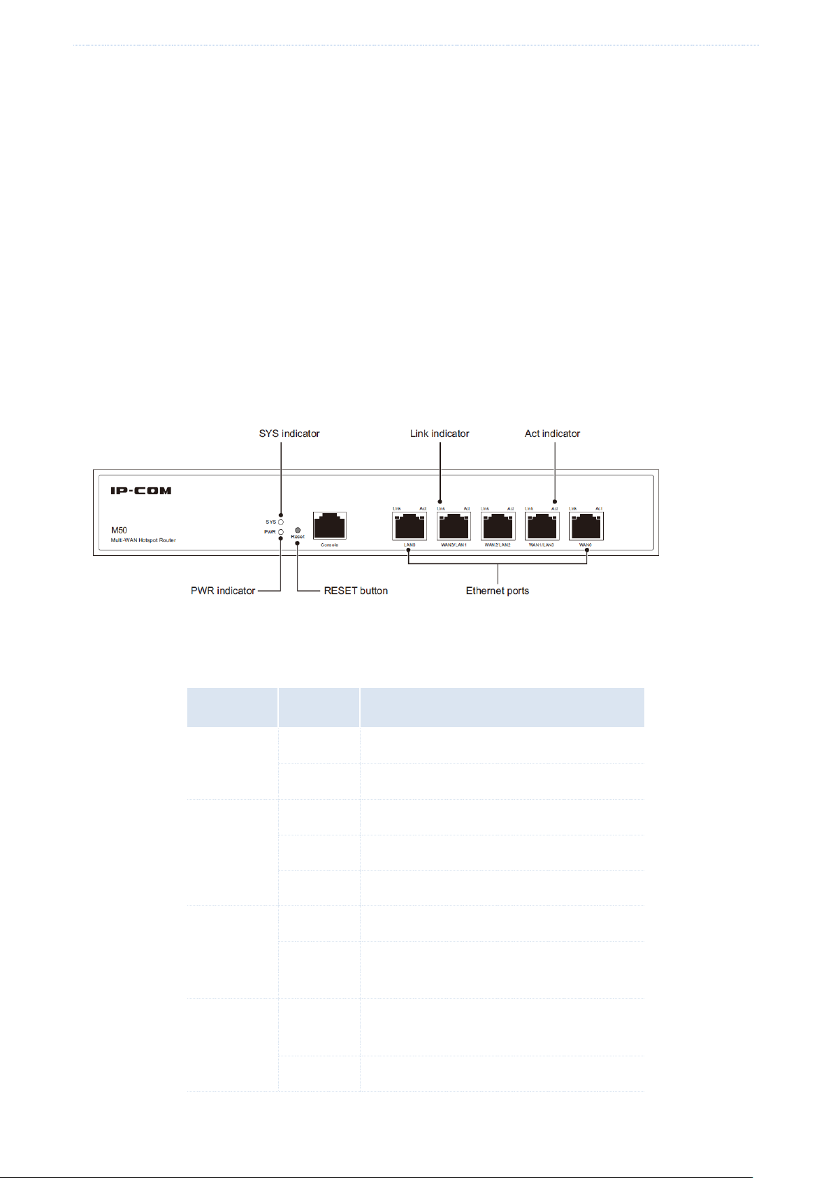
Indicator
Status
Description
PWR
Solid
Power supply is normal.
Off
Power supply is disconnected or fails.
SYS
Blinking
The system is working properly.
Solid
The system is faulty.
Off
System startup is not complete yet.
Link
Solid
The port is connected.
Off
The port is not connected or the connection
is faulty.
Act
Solid
The port is not transmitting or receiving
data.
Blinking
The port is transmitting or receiving data.
The router allows you to add URLs to the database.
Other useful functions
VPN: This function enables you to quickly set up IPsec, PPTP, and L2TP VPNs to facilitate remote access to internal
resources.
Multi-WAN: This function allows a maximum of four ISP network connections.
Hotel mode: This function allows all hosts in a LAN to access the internet with any IP address.
1.3 Appearance
1.3.1 Front panel
The front panel includes 12 LED indicators, 5 RJ45 ports, and 1 RESET button. See the following figure, which
indicates the front panel of M50.
Indicators
There are 1 PWR indicator and 1 SYS indicator. Each RJ45 port has 1 Link indicator and 1 Act indicator.
- 3 -
Page 13
Product overview
Power switch
RJ45 ports
M50 provides five 10/100/1000 Mbps auto-negotiation RJ45 ports. Each RJ45 port has 1 Link indicator and 1 Act
indicator.
The 5 RJ45 ports include 1 LAN port, 1 WAN port, and 3 LAN/WAN ports. You can set the LAN/WAN ports as LAN
or WAN ports as required. By default, the 2 rightmost ports are WAN ports, while the 3 leftmost ports are LAN
ports.
RESET button
This button allows you to restore the default factory settings of the router. To restore the settings, use a pin to
hold down the button for at least 8 seconds and wait about a minute. When the SYS indicator flashes again, you
can infer that the settings are restored successfully.
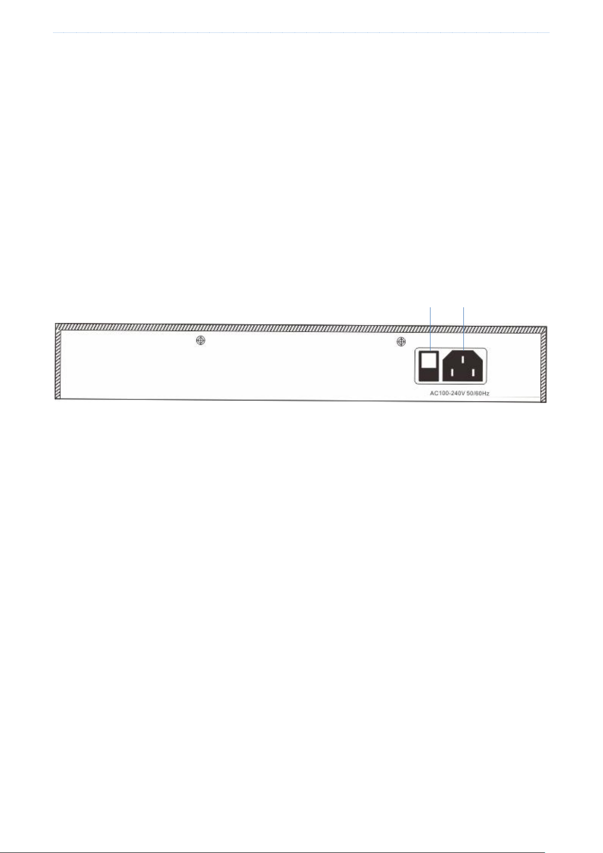
1.3.2 Rear panel
The rear panel includes 1 power switch and 1 power jack. See the following figure.
Power switch
It is used to turn on/off the router.
Power jack
It is used to connect the power cable contained in the product package to the router.
Power Jack
- 4 -
Page 14
Quick internet connection setup
Chapter 2 Quick internet connection setup
This chapter describes:
Logging in to the router web UI
Configuring the router
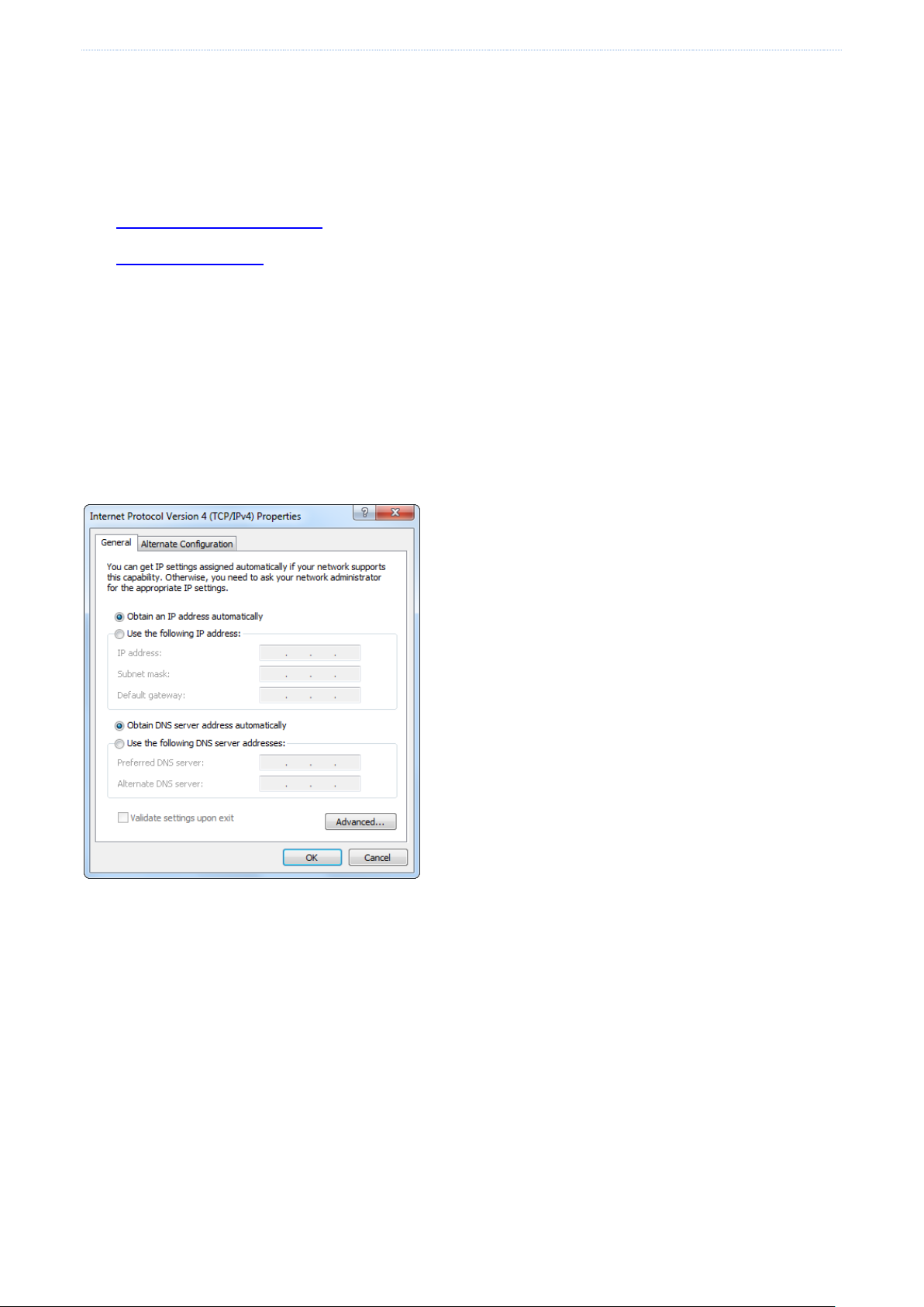
2.1 Logging in to the router web UI
You can use a browser to log in to the router web UI to perform management. To log in to the web UI, connect a
computer to the router (or the switch connected to the router) using an Ethernet cable and perform the following
procedure:
1. Select the Obtain an IP address automatically and Obtain DNS server address automatically options for the
local connection.
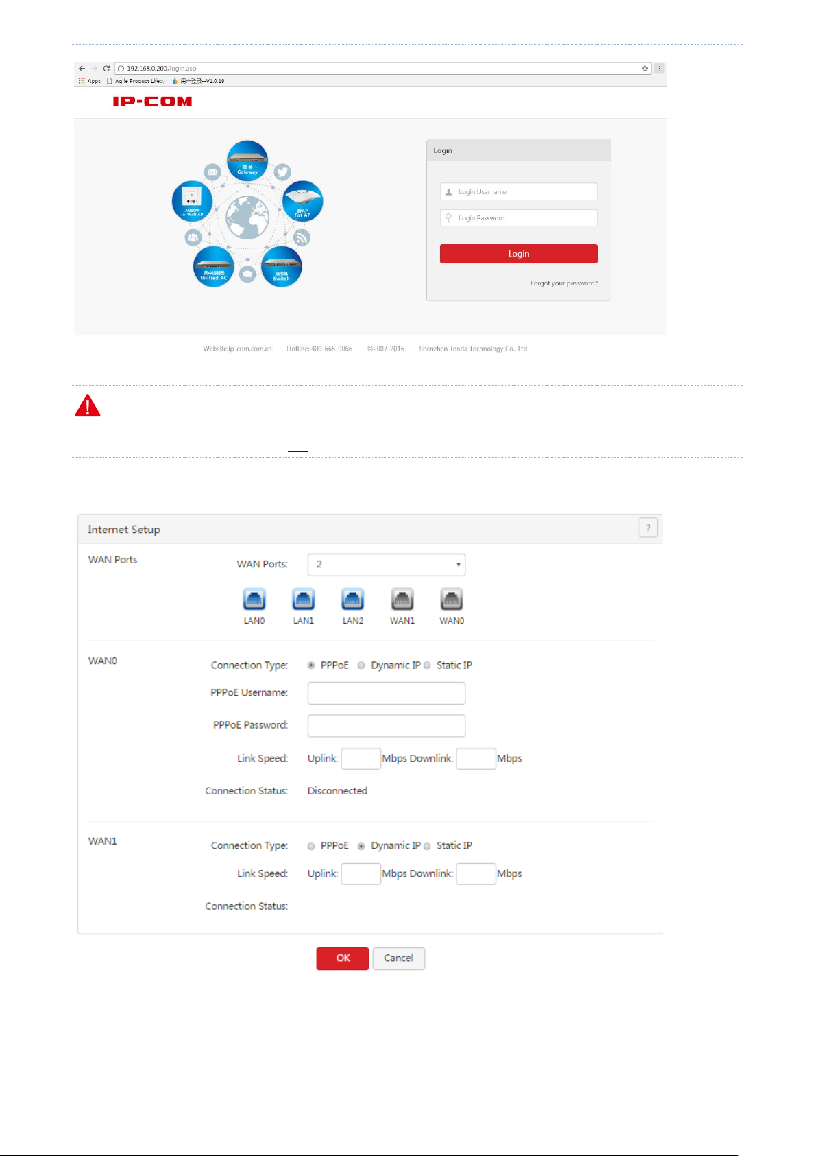
2. Start a browser (such as Internet Explorer) and enter 192.168.0.252 to access the router login page.
3. Enter your user name and password (the default user name and password are admin) and click Login.
- 5 -
Page 15
Quick internet connection setup
Note
If the page does not appear, refer to Q1 in Appendix.
After logging in to the web UI, you can configure the router.
2.2 Configuring the router
By configuring the router, you can enable multiple computers in your LAN to access the internet. Before
- 6 -
Page 16

Quick internet connection setup
Internet Connection
Type
Description
PPPoE
Your internet service provider (ISP) provides a user name and password for you to
access the internet.
Dynamic IP address
Your ISP does not provide any internet connection type information for you or specifies
that you can access the internet using a dynamic IP address.
Static IP address
Your ISP specifies internet connection information including a fixed IP address, a
subnet mask, a default gateway, and DNS servers for you.
configuring the router, consult your ISP on your internet connection type.
Note
The router provides 2 WAN ports. In the following sections, the WAN0 port is used as an example to describe
the configuration method, which is also applicable to the WAN1 port.
By default, the WAN0 port is connected to the internet using PPPoE, while the WAN1 port is connected to the
internet using a dynamic IP address.
All internet access parameters are specified by ISPs. If you are uncertain about the parameters, consult your
ISP.
If a dialog box appears when you configure the router, take measures according to the message in the dialog
box.
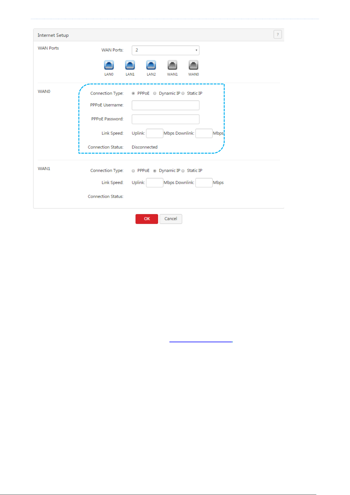
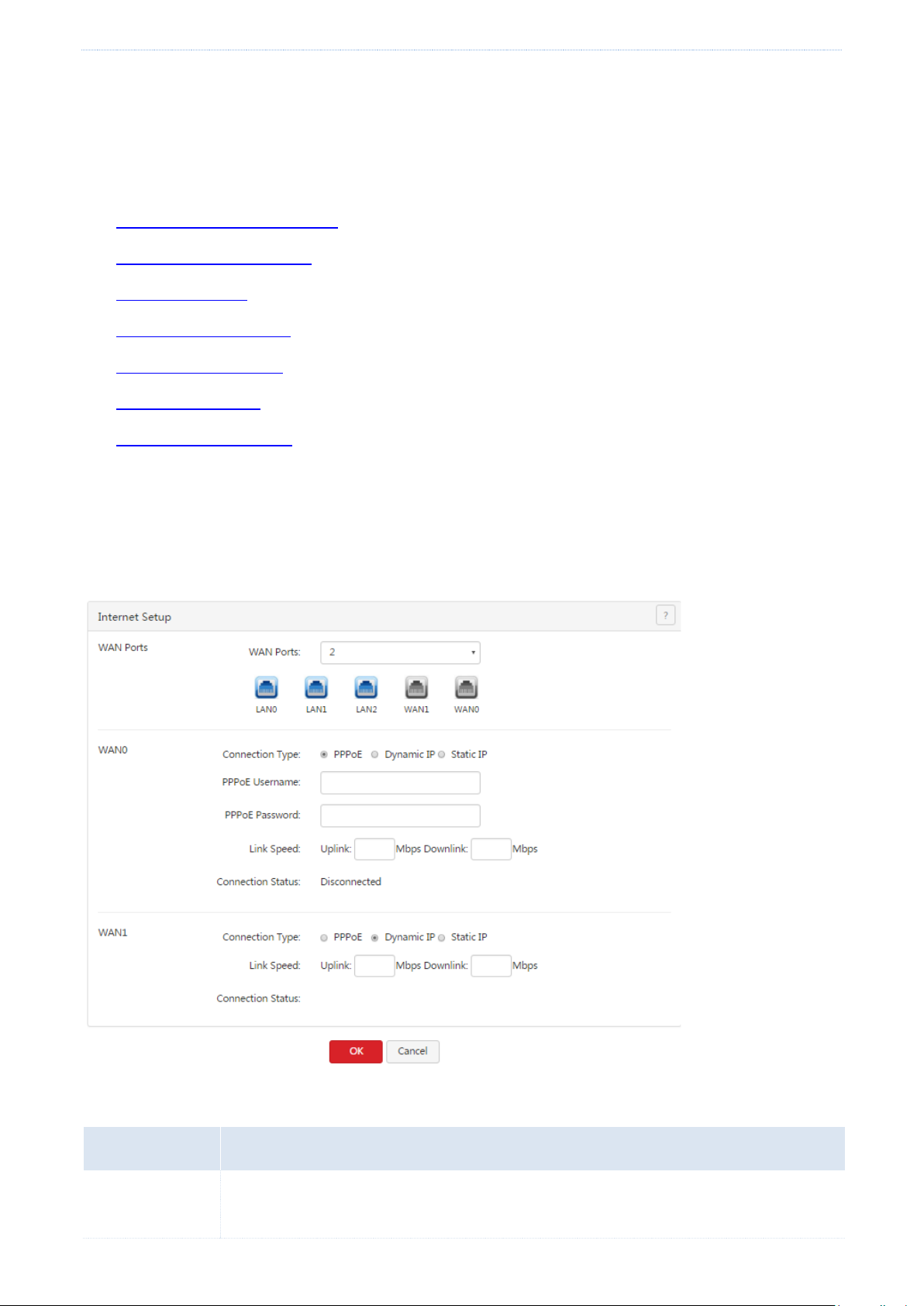
2.2.1 PPPoE
Choose Network > Internet Setup. The following figure shows the configuration page.
- 7 -
Page 17
Quick internet connection setup
Perform the following procedure to configure an internet connection:
1. Set Connection Type to PPPoE.
2. Set PPPoE Username and PPPoE Password to the broadband service user name and password provided by
your ISP.
3. Set Link Speed to the bandwidth of your broadband connection. If you are uncertain about the bandwidth,
consult your ISP.
4. Click OK.
Wait a moment. After Connection Status is changed to Connected, you can access the internet. If the internet is
inaccessible, choose Network > WAN Parameters, and change WAN parameters to resolve the problem.
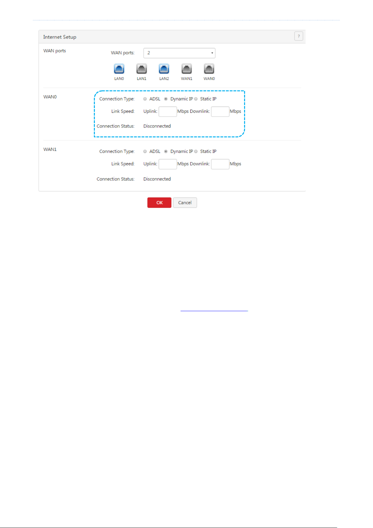
2.2.2 Dynamic IP address
Choose Network > Internet Setup. The following figure shows the configuration page.
- 8 -
Page 18
Quick internet connection setup
Perform the following procedure to configure an internet connection:
1. Set Connection Type to Dynamic IP.
2. Set Link Speed to the bandwidth of your broadband connection. If you are uncertain about the bandwidth,
consult your ISP.
3. Click OK.
Wait a moment. After Connection Status is changed to Connected, you can access the internet. If the internet is
inaccessible, choose Network > WAN Parameters, and change WAN parameters to resolve the problem.
2.2.3 Static IP address
Choose Network > Internet Setup. The following figure shows the configuration page.
- 9 -
Page 19

Quick internet connection setup
Perform the following procedure to configure an internet connection:
1. Set Connection Type to Static IP.
2. Set IP Address, Subnet Mask, Default Gateway, Primary DNS, and Secondary DNS to those provided by your
ISP.
3. Link Speed to the bandwidth of your broadband connection. If you are uncertain about the bandwidth,
consult your ISP.
4. Click OK.
Wait a moment. After Connection Status is changed to Connected, you can access the internet. If the internet is
inaccessible, choose Network > WAN Parameters, and change WAN parameters to resolve the problem.
- 10 -
Page 20
Login
Chapter 3 Login
This chapter describes:
Logging in to the router web UI
Logging out of the router web UI
Web UI layout
Common buttons on the web UI
3.1 Logging in to the router web UI
For details, see section 2.1 “Logging In to the Router Web UI .”
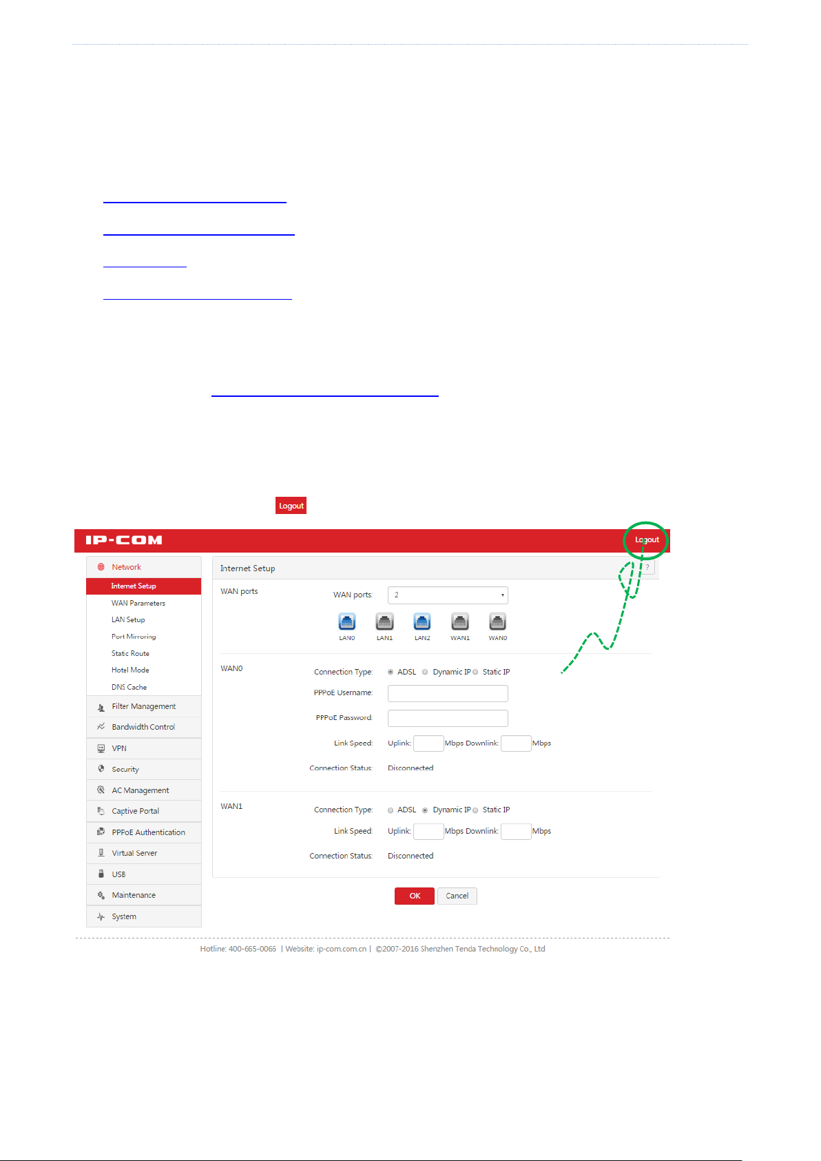
3.2 Logging out of the router web UI
After you log in to the router web UI, the system will log you out if you do not perform any operation within 5
minutes. To log out yourself, click in the upper-right corner.
Click here to log out
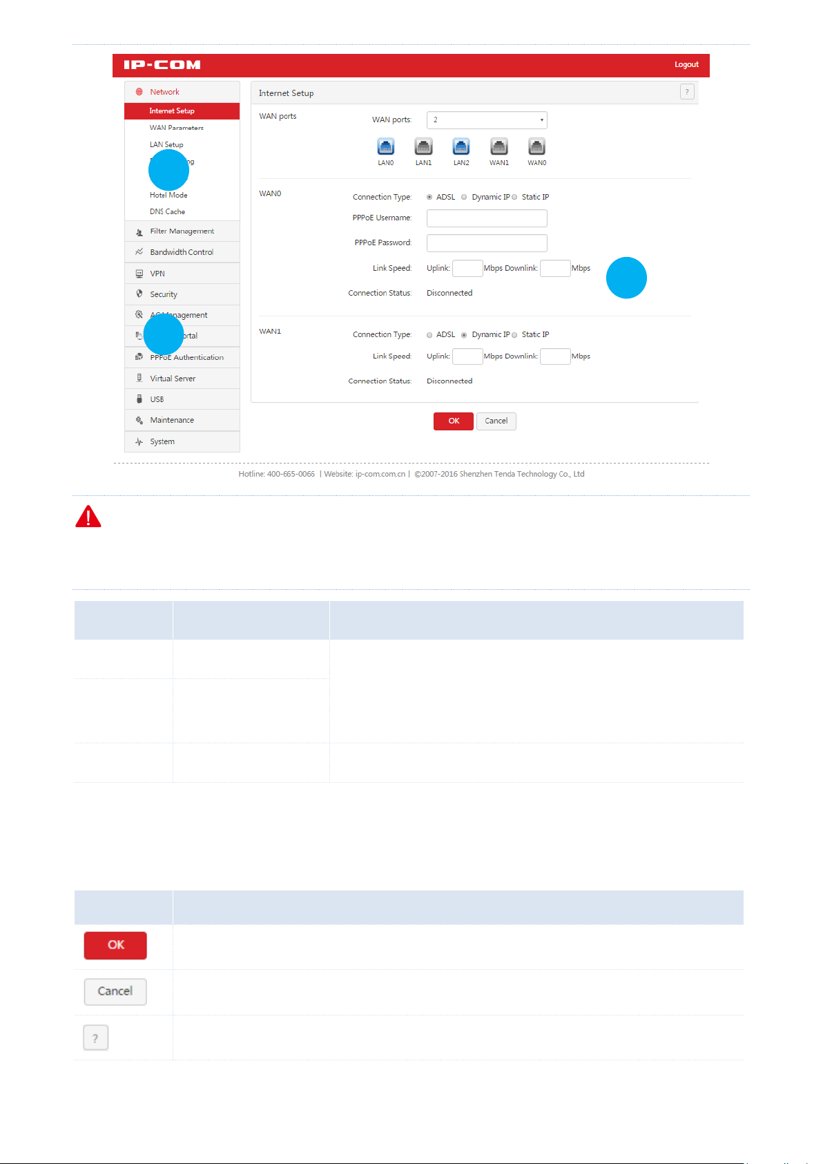
3.3 Web UI layout
The web UI is divided into the level-1 navigation bar, level-2 navigation bar, and configuration area. See the
following figure.
- 11 -
Page 21
Login
SN
Area
Description
❶
Level-1 navigation bar
The navigation bars display router menus. You can easily access
functions by choosing items of the menus. When you choose a
menu item, information corresponding to the menu item appears in
the configuration area.
❷
Level-2 navigation bar
❸
Configuration area
The configuration area enables you to set or view parameters.
Button
Description
It is used to save the settings on the current page and enable the settings to take effect.
It is used to cancel the settings on the current page and restore the original settings.
It is located in the upper-right corner and used to view help information of the parameters on
the current page.
2 1 3
Note
The dimmed functions and parameters on the web UI are functions and parameters not supported by the router
or unavailable for the current configuration.
3.4 Common buttons on the web UI
The following table describes the common management buttons.
- 12 -
Page 22
Network
Parameter
Description
WAN Ports
It specifies the number of WAN ports of the router. By default, the router has 2 WAN ports.
The router supports a maximum of 4 WAN ports. You can change the number as required.
Chapter 4 Network
This chapter describes:
Setting up an internet connection
Setting WAN port parameters
Setting up your LAN
Configuring port mirroring
Configuring a static route
Using the Hotel mode
Configuring the DNS cache
4.1 Setting up an internet connection
This function enables you to share your internet access service among multiple computers on your LAN. To access
the page for setting up an internet connection, choose Network > Internet Setup. See the following figure.
The following table describes the parameters.
- 13 -
Page 23
Network
Parameter
Description
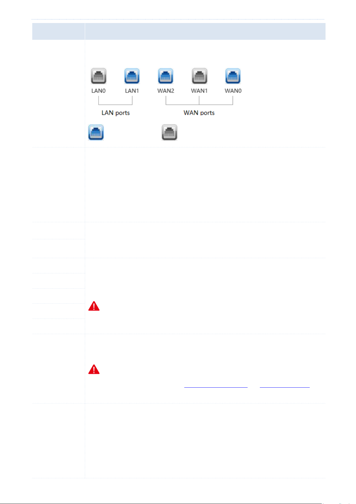
After you change the number of WAN ports, the status of the RJ45 ports changes
accordingly. See the following figure.
: normal connection : disconnected or connection failure
Connection Type
The router can set up an internet connection using PPPoE, a dynamic IP address, or a static
IP address. The connection types are described as follows:
PPPoE: It is used if your ISP provides you with a PPPoE user name and password.
Dynamic IP: It is used if your ISP does not provide you with any internet connection
information.
Static IP: It is used if your ISP provides you with a fixed IP address.
PPPoE Username
A user name and password are required only after you set Connection Type to PPPoE. The
user name and password may be specified on your broadband service note. If the note does
not specify such information, consult your ISP.
PPPoE Password
IP Address
These parameters are required only after you set Connection Type to Static IP. The
information may be specified on your broadband service note. If the note does not specify
such information, consult your ISP.
Note
If your ISP provides you with only 1 DNS IP address, leave Secondary DNS blank.
Subnet Mask
Default Gateway
Primary DNS
Secondary DNS
Link Speed
It specifies the bandwidth of your broadband connection. If you are uncertain about the
bandwidth, consult your ISP.
Note
If you leave this parameter blank, the smart bandwidth control and smart load balacing
functions cannot take effect. Therefore, it is recommended that you set this parameter.
Connection
Status
It displays the WAN port connection status of the WAN port for accessing the internet.
Connected: A WAN port of the router is connected using an Ethernet cable and has
obtained IP address information.
Authenticated success: The router has successfully dialed up and obtained IP address
information.
Connecting…: The router is connecting to an upstream network device.
- 14 -
Page 24

Network
Parameter
Description
Disconnected: No connection is set up or connection fails. In this case, verify the cable
connection and internet connection information, or consult your ISP.
If a state not specified here appears, take measures based on the message corresponding to
the state.
4.2 Setting WAN port parameters
If you have set internet connection parameters but your computer cannot access the internet, try modifying WAN
port parameters.
To access the page for modifying WAN port parameters, choose Network > WAN Parameters. See the following
figure.
4.2.1 WAN speed
If you have correctly connected an Ethernet cable to a WAN port of the router but the Link indicator of the WAN
port does not turn on or it takes over 5 seconds for the Link indicator to turn on after the cable is connected, you
can try resolving the problem by changing WAN Speed of the port to 10M half duplex or 10M full duplex.
Otherwise, it is recommended that you retain the default setting Auto of WAN Speed.
4.2.2 MTU
Maximum Transmission Unit (MTU) indicates the maximum size of a packet that can be transmitted by a network
device. If Connection Type is set to PPPoE, the default MTU value is 1492. If Connection Type is set to Dynamic IP
or Static IP, the default MTU value is 1500. In normal cases, the default values are recommended. If you
encounter any of the following problems, try gradually reducing the value (recommended range: 1400 to 1500) to
- 15 -
Page 25

Network
MTU Value
Usage
1500
It is the most common value for non-PPPoE connections and non-VPN connections.
1492
It is used for PPPoE connections.
1472
It is the maximum value for the pinging function. (If a greater value is used, packets are
splitted.)
1468
It is used for DHCP, which assigns dynamic IP addresses.
1436
It is used for VPNs or PPTP.
find the suitable value that does not lead to the problem:
Some websites are not accessible or some secure websites cannot be displayed properly (such as the login
pages of online banking websites and Alipay’s website).
Emails cannot be received or servers such as FTP and POP servers are not accessible.
4.2.3 MAC address
If your ISP has bound your internet account with the MAC address (physical address) of your computer, the router
cannot access the internet despite internet connection parameters have been set on the router. In this case, only
the computer can use the account to access the internet. The computer refers to the one used to verify your
internet accessibility after your ISP creates the account for you.
You can try MAC address cloning method 1 or 2 described in the following section to resolve the problem.
Method 1:
1. Connect the computer to the router.
2. Log in to the router web UI on the computer.
3. Choose Network > WAN Parameters.
4. Set MAC Address corresponding to the WAN port used to access the internet to Clone Local Host’s MAC.
5. Click OK.
Method 2:
1. Connect a computer other than the above-mentioned computer to the router.
2. Log in to the router web UI on the computer.
3. Choose Network > WAN Parameters.
4. Set MAC Address corresponding to the WAN port used to access the internet to Custom.
- 16 -
Page 26
Network
5. Enter the MAC address of the computer with internet accessibility.
6. Click OK.
To restore the default MAC address of the WAN port, choose Network > WAN Parameters, set MAC Address
corresponding to the WAN port to Default MAC, and click OK.
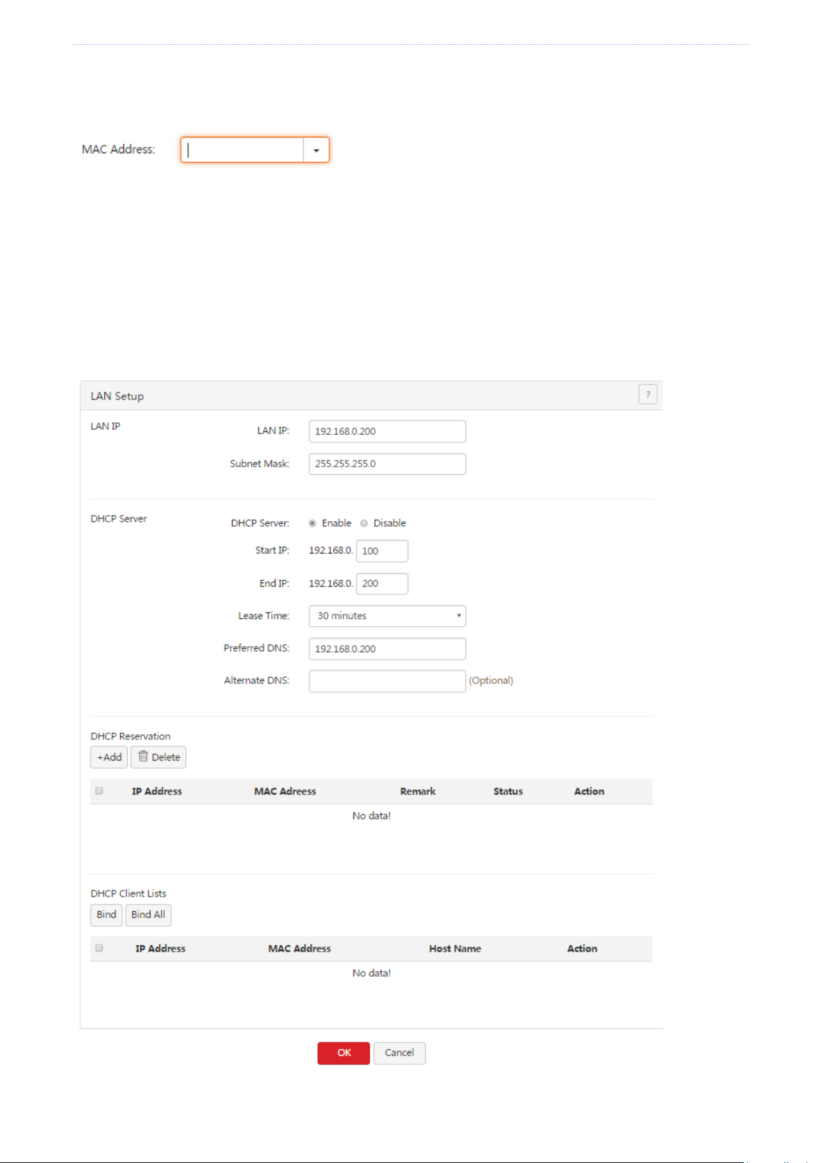
4.3 Setting up your LAN
Choose Network > LAN Setup. On the page that appears, you can set the LAN IP address and DHCP server
parameters for the router.
- 17 -
Page 27
Network
Parameter
Description
DHCP Server
It is used to enable or disable the DHCP function of the router.
4.3.1 LAN port IP addresses
The LAN IP address is set for the router to communicate within your LAN and for you to manage the router. The
default LAN IP address and subnet mask of the router are 192.168.0.252 and 255.255.255.0 respectively.
Generally, you do not need to change the LAN IP address, unless it is in conflict with another IP address. For
example, the WAN IP address and LAN IP address of the router may be in the same network segment or the
default IP address 192.168.0.252 has been assigned to a device on the LAN.
After the LAN IP address is changed, the message shown in the following figure appears.
When the progress bar is complete, the login page appears. If the page does not appear, verify that the Obtain an
IP address automatically option is selected for the local connection of your computer and an IP address is
assigned from the router to your computer. Then, try accessing the login page with the new LAN IP address.
Note
If the new and old LAN IP addresses belong to different network segments, the router changes the DHCP address
pool accordingly so that the IP addresses in the pool belong to the same network segment as the new LAN IP
address.
4.3.2 DHCP server
The DHCP server automatically assigns IP addresses, subnet masks, gateway IP addresses, and DNS IP addresses to
computers on your LAN. If you disable the DHCP function, you need to manually configure this information on the
computers so that the computers can access the internet. Disable this function only when necessary.
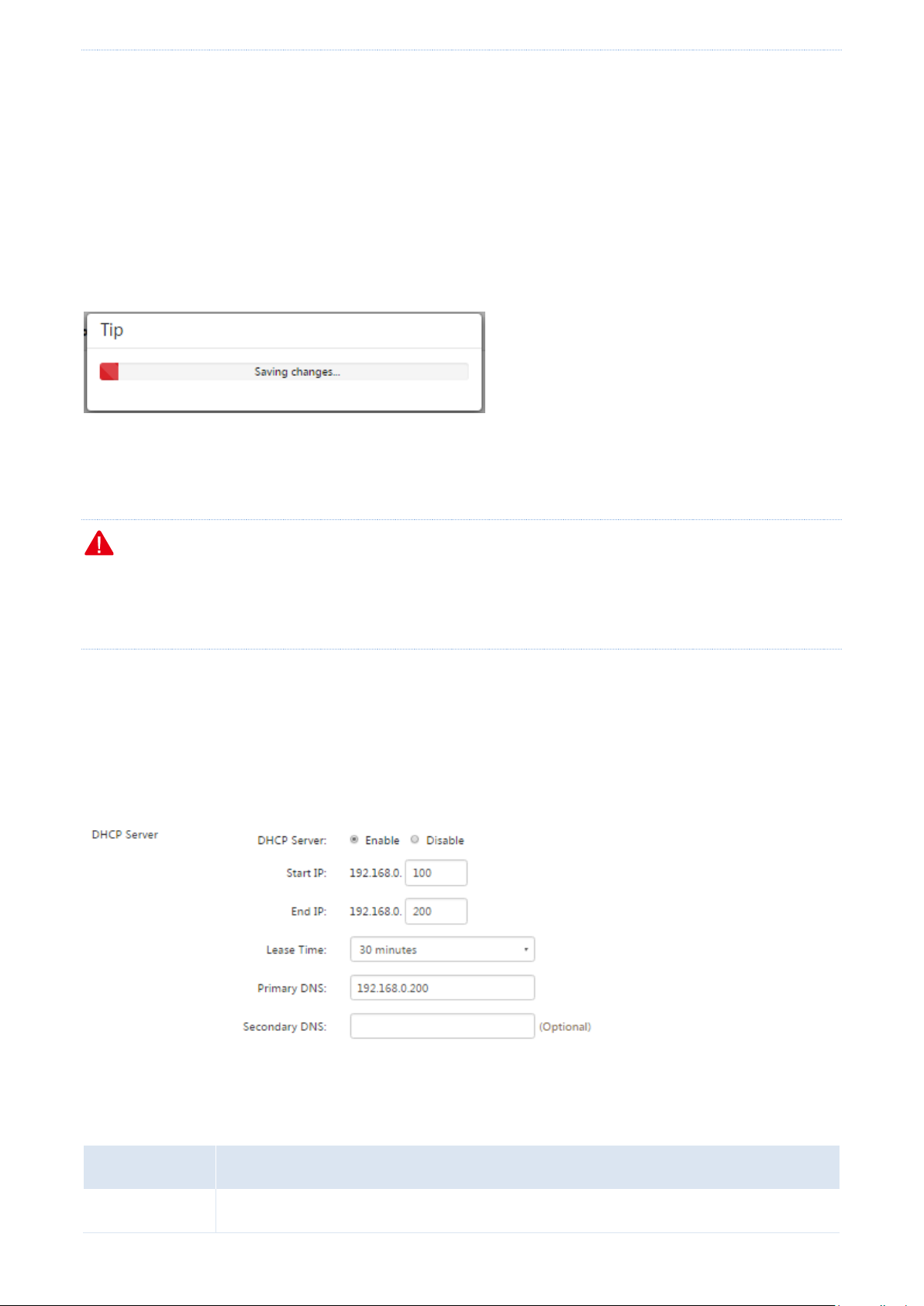
The following table describes the parameters.
- 18 -
Page 28

Network
Parameter
Description
Start IP
It specifies the start IP address of the DHCP address pool (range of IP addresses that can be
assigned by the DHCP server). The default value is 192.168.0.100.
End IP
It specifies the end IP address of the DHCP address pool. The default value is 192.168.0.200.
Note
The start and end IP addresses must belong to the same network segment as the LAN IP
address of the router.
Lease Time
It specifies the validity of an IP address assigned by the DHCP server to a computer. When
the IP address expires:
If the computer is connected to the router, the computer automatically updates the
lease time to continue using the IP address.
If the computer is not connected to the router (for example, the computer is shut
down or the wired or wireless connection of the computer is released), the router
releases the IP address. Then, when another computer requests an IP address, the
router can assign the released IP address to the computer.
Change the default settings only when necessary.
Primary DNS
It specifies the primary DNS IP address that the DHCP server assigned to computers on your
LAN. The router can function as a DNS proxy. Therefore, the LAN IP address of the router is
set as the primary DNS IP address by default.
Note
Generally, the default value is recommended. If you need to change the value ensure that
the new value is the IP address of a correct DNS server or DNS proxy, so that the computers
on your LAN can access the internet properly.
Secondary DNS
It specifies the secondary DNS IP address assigned by the DHCP server to computers on
your LAN. If the value is blank, the DHCP server does not assign the IP address.
4.3.3 Static IP addresses assignment using DHCP
The filter management, flow control, and virtual server functions of the router are implemented based on IP
addresses assigned to computers. These functions fail when the IP addresses change and as a result you need to
update rules for the functions accordingly.
The function of static IP address assignment using DHCP helps address this problem. It allows the DHCP server to
assign a fixed IP address to a computer, enabling the filter management, flow control, and virtual server functions
to work properly.
- 19 -
Page 29
Network
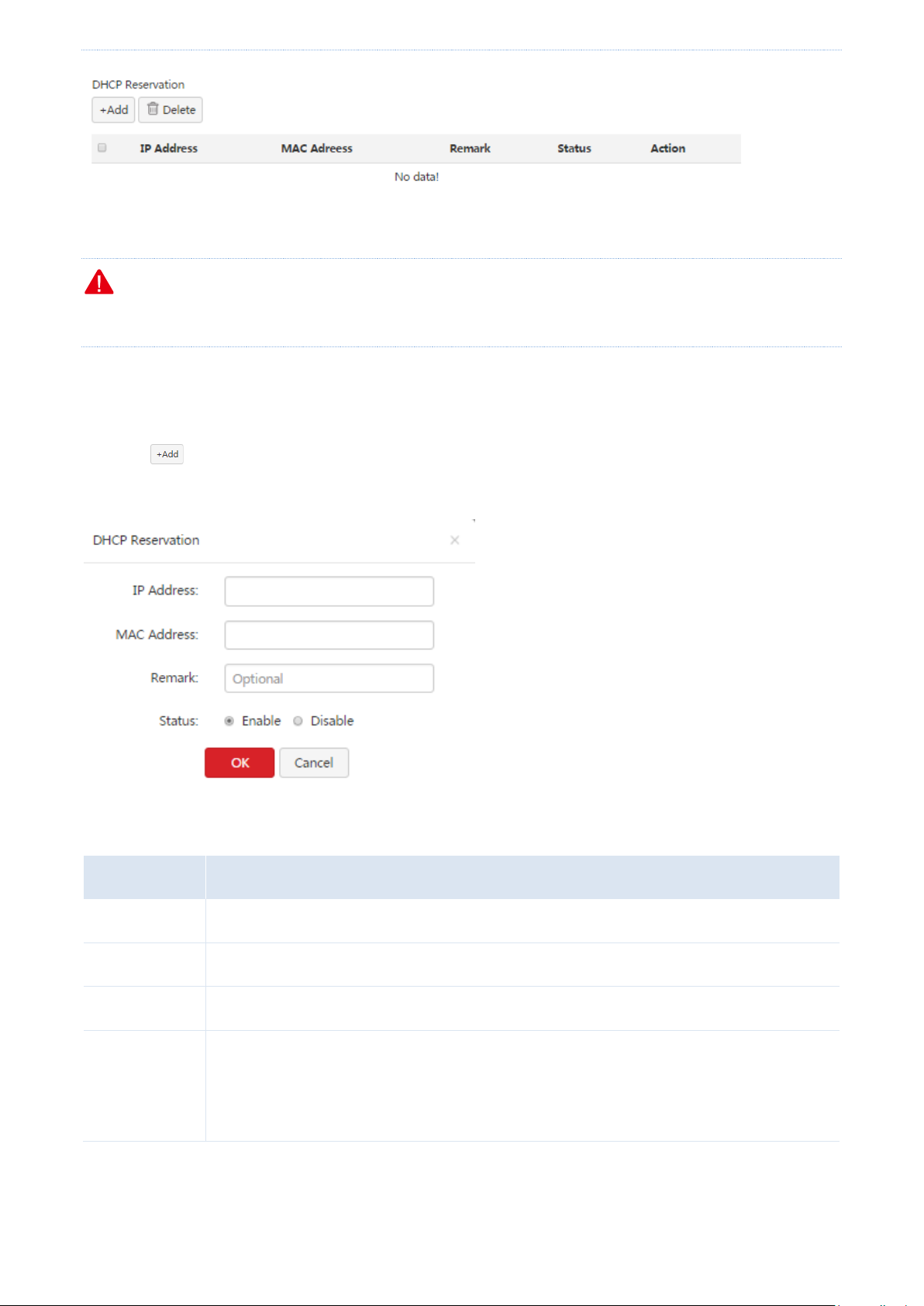
Parameter
Description
IP Address
It specifies the static IP address assigned by the DHCP server.
MAC Address
It specifies the MAC address bound to the static IP address assigned to a computer.
Remark
It specifies the description of a rule. This parameter is optional.
Status
It specifies whether to enable a rule. The options include:
Enable: It indicates that a rule is enabled.
Disable: It indicates that a rule is disabled.
Note
When using this function, ensure that the DHCP server function of the router has been enabled.
Adding a rule
1. Choose Network > LAN Setup.
2. Click in the DHCP Reservation area.
The DHCP Reservation dialog box appears.
The following table describes the parameters.
3. Set the parameters and click OK.
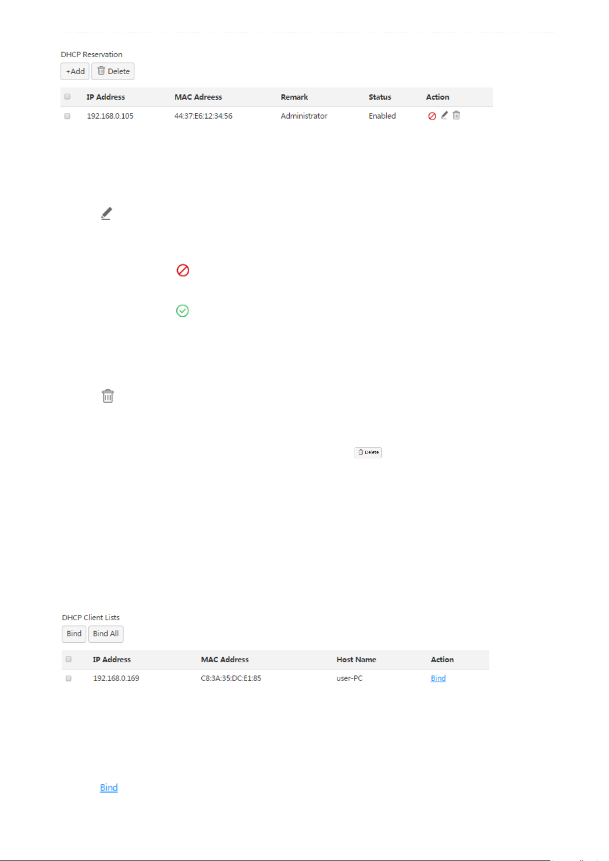
The LAN Setup page appears, showing the added rule. See the following figure.
- 20 -
Page 30
Network
Modifying a rule
1. Choose Network > LAN Setup.
2. Click corresponding to a rule to be modified.
3. Modify the rule.
4. To disable a rule, click corresponding to the rule.
5. To enable a rule, click corresponding to the rule.
Deleting a rule
1. Choose Network > LAN Setup.
2. Click corresponding to a rule to be deleted.
The rule is deleted.
3. To delete multiple rules at the same time, select them and click .
4.3.4 DHCP Client List
If the DHCP server function of the router is enabled, you can refer to the DHCP client list for details (including IP
addresses, MAC addresses, and host names) of the clients that obtain IP addresses from the DHCP server.
In addition, you can quickly bind clients with their current IP addresses so that the DHCP server always assigns the
IP addreses to the clients.
Binding a client
1. Choose Network > LAN Setup.
2. Click corresponding to the client to the bound in the DHCP Client Lists area.
The client is bound with its current IP address.
- 21 -
Page 31

Network
Binding clients in batches
1. Choose Network > LAN Setup.
2. Select the clients to be bound in the DHCP Client Lists area and click .
The clients are bound with their current IP addresses.
Binding all clients
1. Choose Network > LAN Setup.
2. Click in the DHCP Client Lists area.
All the clients are bound with their current IP addresses.
4.4 Configuring port mirroring
4.4.1 Overview
M50 provides the port mirroring function, which enables you to replicate data from one or more ports of the
router (mirrored ports) to a specified port (mirroring port). Generally, a data monitoring device is deployed at the
mirroring port so that network an administrator can monitor traffic, analyze performance, and diagnose faults in
real time. The following figure shows the network topology for port mirroring.
The mirroring port of M50 is fixed to LAN0 and cannot be changed in the current version.
4.4.2 Configuring port mirroring
To access the port mirroring page, choose Network > Port Mirroring. The following figure shows the default
setting.
- 22 -
Page 32

Network
Parameter
Description
Port Mirroring
It is used to enable or disable the port mirroring function. The default option is Disable.
Mirroring Port
It indicates the monitoring port. A piece of monitoring software must be installed on the
computer with this port to perform monitoring. The default mirroring port is LAN0 and
cannot be changed in the current version.
Mirrored Port
It specifies the monitored ports. After the port mirroring function is enabled, packets of
the mirrored ports are replicated to the mirroring port for monitoring.
If this function is required, set Port Mirroring to Enable, select mirrored ports, and click OK.
The following table describes the parameters.
4.4.3 Port mirroring configuration example
Networking requirement
An enterprise has used M50 to set up a LAN. Recently, internet access failures occur frequently and the network
administrator needs to capture data packets from the WAN and LAN ports of the router for analysis.
Configuration procedure
1. Choose Network > Port Mirroring and set Port Mirroring to Enable.
2. Set Mirrored Port to LAN1, LAN2, WAN1, and WAN0.
3. Click OK.
Verification
Run monitoring software such as Wireshark on the monitoring computer and verify that the software can capture
data packets from the mirrored ports.
- 23 -
Page 33

Network
4.5 Configuring a static route
4.5.1 Overview
Routing is an operation to select the optimal route for delivering data from a source to a destination. A static route
is a special route configured manually, which is simple, efficient, and reliable. Proper static routes help reduce
route selection issues and prevent overload caused by route selection data flows, accelerating packet forwarding.
To define a static route, specify the network segment and subnet mask used to identify a destination network or
host, the gateway IP address, and the router WAN port for forwarding packets. After a static route is defined, all
the packets indented for the destination of the static route are directly forwarded through the router WAN port to
the gateway IP address.
Note
If only static routes are used in a large-scale complex network, destinations may be unreachable in case of a
network fault or topology change, which results in network interruption. If the problem occurs, manually modify
the static routes.
4.5.2 Configuring a static route
To access the page for configuring a static route, choose Network > Static Route. See the following figure.
Adding a static route
1. Choose Network > Static Route and click . The Add dialog box appears.
- 24 -
Page 34

Network
Parameter
Description
Destination Network
It specifies the IP address or IP address segment of the destination network.
Subnet Mask
It specifies the subnet mask of the IP address of the destination network.
Gateway
It specifies the IP address of the next hop of the packets forwarded from the router
WAN port.
Port
It specifies the WAN port that forwards packets.
The following table describes the parameters.
2. Set the parameters and click OK.
3. Choose Network > Static Route and view the added static route.
The available static routes are displayed in the Route Table module on the page. See the following figure.
In the route table, the record where Destination Network and Subnet Mask are 0.0.0.0 indicates the default route
of the router. If no route exactly matching the destination address of a packet is found in the route table, the
router uses the default route to forward the packet. The route containing the gateway IP address 0.0.0.0 is a direct
route, which means that the destination network is directly connected to the router using the port specified in the
route.
- 25 -
Page 35

Network
Note
If a static route is in conflict with a user-defined multi-WAN policy, the static route takes preference over the
policy.
Modifying a static route
1. Choose Network > Static Route.
2. Click corresponding to the static route to be modified in the Static Route area.
3. Modify the static route.
Deleting a static route
1. Choose Network > Static Route.
2. Click corresponding to the static route to be deleted in the Static Route area.
The static route is deleted.
4.5.3 Static route configuration example
Networking requirement
An enterprise uses M50 for network construction. The internet is inaccessible to the enterprise LAN. The WAN0
port of M50 accesses the internet using a PPPoE connection and the WAN1 port of M50 accesses the enterprise
LAN using a dynamic IP address. Users on the M50 LAN are allowed to access both the internet and enterprise
LAN.
Assume that the PPPoE user name and password are ip-com and the internet bandwidth and LAN bandwidth are
100 Mbps.
Configuration procedure
On the M50 web UI, set up an internet connection and configure a static route to address the requirement.
- 26 -
Page 36

Network
I. Set up an internet connection.
1. Choose Network > Internet Setup.
2. Set internet connection parameters.
3. Click OK.
II. Configure a static route.
1. Choose Network > Static Route.
2. Click .
3. Configure the static route shown in the following figure.
The configured static route appears in the Route Table module. See the following figure.
- 27 -
Page 37

Network
Verification
Access the internet and enterprise LAN using a computer on the M50 LAN.
Note
If the enterprise LAN is connected to the internet, as shown in the following figure, M50 may point its default
route to the other router, resulting in incorrect routing. In this case, choose Network > Internet Setup and set Link
Speed of the WAN1 port to a value far smaller than the value of Link Speed of the WAN0 port.
If the preceding case occurs, it is recommended that you disable the smart bandwidth control function of M50
and use a user-defined multi-WAN policy to ensure that all M50 LAN users access the internet through the WAN0
port of M50. Otherwise, a network exception may occur.
4.6 Using the Hotel mode
4.6.1 Overview
- 28 -
Page 38

Network
Generally, IP addresses are assigned automatically an M50 LAN for accessing the internet. In addition, IP addresses,
gateway IP addresses, and DNS IP addresses can be manually configured for an M50 LAN to access the internet.
Usually, a hotel has heavy traffic. Some of its guests configure their network adapters to obtain IP addresses
automatically, some assign static IP addresses to their network adapters, and still some do not know how to
configure their network adapters. In this case, hotel employees often need to help their guests configure network
adapters, which bothers both the employees and guests.
To address this issue, M50 offers the Hotel mode. After a hotel enables this mode, computers in the LAN of the
hotel can access the internet using any IP addresses (including IP addresses out of the IP address groups
configured on M50), gateway IP addresses, and DNS IP addresses. Therefore, a guest of the hotel can access the
internet through the hotel LAN without changing the network configuration of his/her network adapter.
4.6.2 Configuring the Hotel mode
To access the page for configuring the Hotel mode, choose Network > Hotel Mode. The following figure shows the
default Hotel mode setting.
To enable the Hotel mode, select Enable and click OK.
4.7 Configuring the DNS cache
4.7.1 Overview
M50 supports the DNS cache function, which enables the router to cache DNS-resolved information about
websites accessed by users. When other users access the websites, the router directly uses the information in the
cache to direct the users to the websites without accessing the DNS server. This improves the website accessing
speed.
4.7.2 Configuring the DNS cache
To access the page for configuring the DNS cache, choose Network > DNS Cache. See the following figure.
By default, the DNS cache contains 1,000 entries. A maximum of 10,000 entries are allowed.
- 29 -
Page 39

Filter management
Chapter 5 Filter management
5.1 Overview
This chapter describes:
Setting IP address groups and time groups
Setting the MAC address filter
Setting the port filter
Setting the web filter
Setting multi-WAN policies
5.1.1 Function description
IP address group and time group
This function sets IP address groups and time groups. Time groups are used for the MAC address filter, port filter,
web filter, and user-defined bandwidth control, while IP address groups are used for the port filter, web filter, and
user-defined multi-WAN policies.
Note
If you set an IP address group, the LAN devices not included in the group cannot access the internet. In this case,
add the devices that require internet accessibility to the group.
MAC address filter
You can set a MAC address whitelist and/or a MAC address blacklist to enable or disable users to access the
internet through the router. The whitelist and blacklist are described as follows:
Whitelist: Users in the whitelist are allowed to access the internet.
Blacklist: Users in the blacklist are not allowed to access the internet.
Port filter
The protocols of various services available over the internet use dedicated port numbers. The common service
port numbers range from 0 to 1023 and are generally assigned to specific services.
A port filter prevents LAN users from accessing certain internet services by disabling the users to access the port
numbers of the services.
Web filter
A web filter prevents LAN users from accessing specified types of website for controlling internet accessibility of
LAN users so that they will not spend time on websites irrelevant to their duties. Before you add web filter rules,
add web categories.
- 30 -
Page 40

Filter management
Step
Task
Description
1
Set time groups.
Time groups are required when a MAC address filter is set. Choose Filter
Management > IP Group & Time Group and set time groups.
2
Set a MAC address filter.
Choose Filter Management > MAC Filter and set a MAC address filter.
Step
Task
Description
1
Set time groups.
Time groups are required when a port filter or web filter is set.
Choose Filter Management > IP Group & Time Group and set time
groups.
2
Set IP address groups.
IP address groups are required when a port filter or web filter is set.
Choose Filter Management > IP Group & Time Group and set IP address
groups.
3
Set a port filter or a web
filter.
Choose Filter Management > Port Filter and set a port filter.
Choose Filter Management > Web Filter and set a web filter.
Multi-WAN policy
The router has 2 WAN ports by default but allows a maximum of 4 WAN ports. When multiple WAN ports are
operational at the same time, an appropriate multi-WAN policy can greatly improve the bandwidth usage of the
router. The router supports the following types of multi-WAN policy:
Smart load balancing (default): If such a policy is applied, the router automatically distributes traffic based on
the following rules through the WAN ports to achieve load balancing:
- If the usage of the bandwidths specified by Link Speed preset on the Network > Internet Setup page is
lower than 50%, the router distributes traffic proportionately according to the ratio between the
bandwidths of the ports.
- If the usage of the bandwidth on a WAN port specified by Link Speed preset on the Network > Internet
Setup page reaches or exceeds 50%, the router distributes traffic preferably to the port with more
available bandwidth.
Custom policy: Such a policy is configured by an administrator to distribute data of specified IP address
groups to specified WAN ports.
5.1.2 Configuration instruction
Setting a MAC address filter
Setting a port filter or web filter
- 31 -
Page 41

Filter management
Step
Task
Description
1
Set IP address groups.
IP address groups are required when a multi-WAN policy is customized.
Choose Filter Management > IP Group & Time Group and set IP address
groups.
2
Customize a multi-WAN
policy.
Choose Filter Management > Multi-WAN Policy and customize a
multi-WAN policy.
Customizing a multi-WAN policy
Setting a multi-WAN policy for smart load balancing
1. Choose Filter Management > Multi-WAN Policy.
2. Select Smart Load Balancing.
5.2 Setting IP address groups and time groups
To access the page for setting IP address groups and time groups, choose Filter Management > IP Group & Time
Group. See the following figure.
5.2.1 Setting time groups
Adding a time group
1. On the Filter Management > IP Group & Time Group page.
2. Click in the Time Group Config area.
The Add dialog box appears.
- 32 -
Page 42

Filter management
Parameter
Description
Name
It specifies the name of a time group. Duplicate group names are not allowed.
Time
It specifies the start time and end time in a day. 00:00~00:00 indicates a whole day.
Day
It specifies the days of week included.
The following table describes the parameters.
3. Set the parameters and click OK.
The IP Group & Time Group page appears, showing the added time group. See the following figure.
Modifying a time group
1. Choose Filter Management > IP Group & Time Group.
2. Click corresponding to an available time group.
3. Modify the group.
If the time group has been referenced, the reference is updated when group modification is complete.
Deleting a time group
1. Choose Filter Management > IP Group & Time Group.
2. Click corresponding to a time group to be deleted.
The group is deleted.
- 33 -
Page 43

Filter management
Parameter
Description
Name
It specifies the name of an IP address group. Duplicate group names are not allowed.
IP Range
It specifies the start IP address and end IP address of an IP address group.
3. To delete multiple time groups at the same time, select them and click .
Note
A time group that has been referenced cannot be deleted.
5.2.2 Setting IP address groups
Note
If you set an IP address group, the LAN devices not included in the group cannot access the internet. In this case,
add the devices that require internet accessibility to the group.
Adding an IP address group
1. Choose Filter Management > IP Group & Time Group.
2. Click in the IP Group Config area.
The Add dialog box appears.
The following table describes the parameters.
3. Set the parameters and click OK.
The IP Group & Time Group page appears, showing the added IP address group. See the following figure.
- 34 -
Page 44
Filter management
Modifying an IP address group
1. Choose Filter Management > IP Group & Time Group.
2. Click corresponding to an available IP address group.
3. Modify the group.
If the IP address group has been referenced, the reference is updated when group modification is complete.
Deleting an IP address group
1. Choose Filter Management > IP Group & Time Group.
2. Click corresponding to an IP address group to be deleted.
The group is deleted.
3. To delete multiple IP address groups at the same time, select them and click .
Note
An IP address group that has been referenced cannot be deleted.
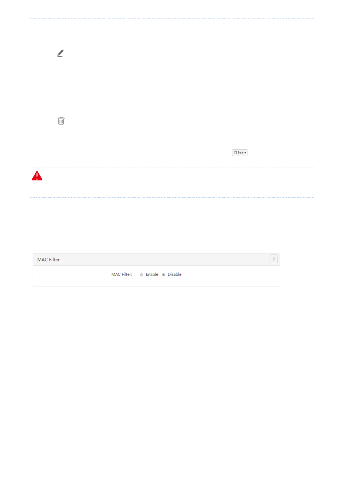
5.3 Setting the MAC address filter
To access the page for setting the MAC address filter, choose Filter Management > MAC Filter. See the following
figure.
5.3.1 Setting the MAC address filter
Enabling the MAC address filter
1. Choose Filter Management > MAC Filter.
2. Set MAC Filter to Enable.
3. Click OK.
The MAC address filter is enabled. Then, you can set MAC address filtering rules.
- 35 -
Page 45
Filter management
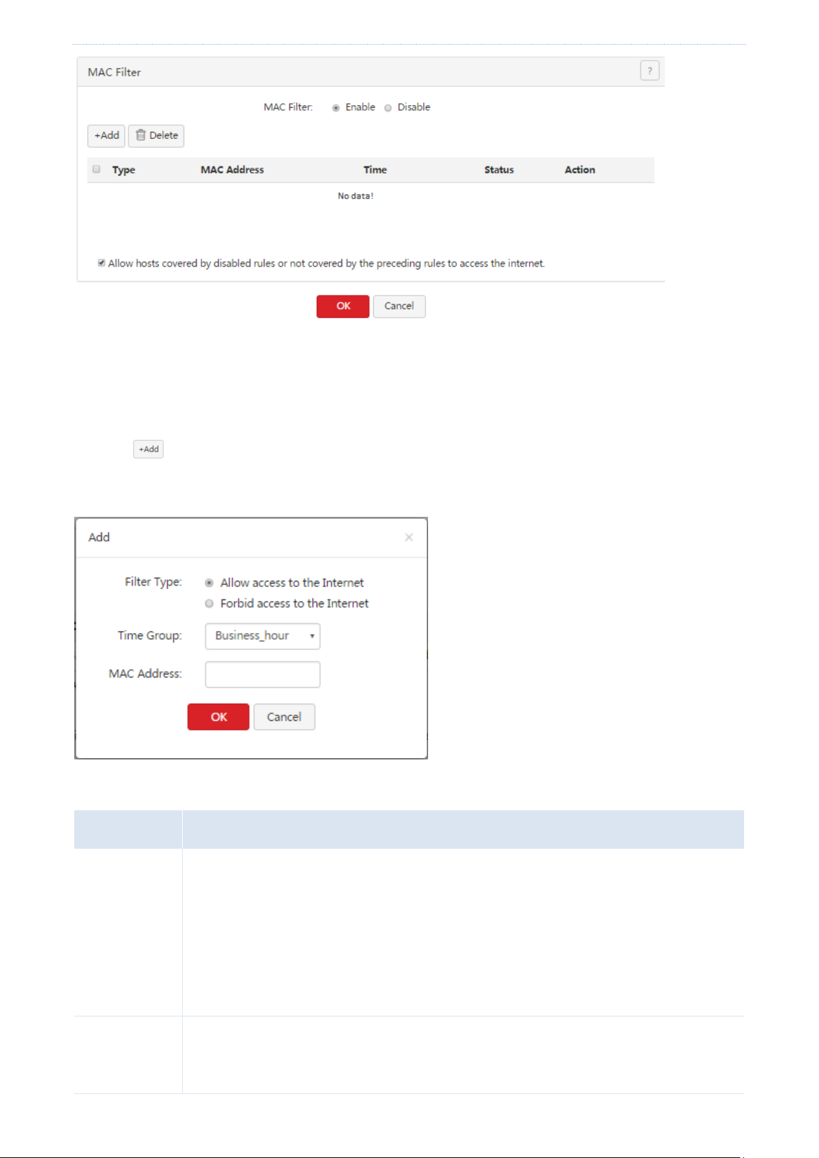
Parameter
Description
Filter Type
It specifies the type of a MAC address filter. The options include
Allow access to the internet: This option indicates the whitelist function. If this option is
used, users with specified MAC addresses can access the internet within specified
periods.
Forbid access to the internet: This option indicates the blacklist function. If this option is
used, users with specified MAC addresses cannot access the internet within specified
periods.
Time Group
It specifies the referenced time group that indicates the validity period of a rule.
Time groups must be configured in advance on the Filter Management > IP Group & Time
Group page.
Setting MAC address filtering rules
Adding a rule
1. Choose Filter Management > MAC Filter.
2. Click .
The Add dialog box appears.
The following table describes the parameters.
- 36 -
Page 46

Filter management
Parameter
Description
MAC Address
It specifies the MAC addresses to which a rule is applicable.
Parameter
Description
Status
It indicates whether a rule is enabled. After a rule is added, it enters the Enabled state by
default.
To disable a rule, click corresponding to the rule. To enable a rule, click
corresponding to the rule.
Allow hosts
covered by
disabled rules
or not covered
by the
preceding rules
to access the
internet.
If it is selected, hosts covered by rules in Disabled state and hosts not covered by rules
are allowed to access the internet.
If it is not selected, hosts covered by rules in Disabled state and hosts not covered by
rules are not allowed to access the internet.
3. Set the parameters and click OK.
The MAC Filter page appears, showing the added rule. See the following figure.
The following table describes the parameters.
Modifying a rule
1. Choose Filter Management > MAC Filter.
2. Click corresponding to a MAC address filtering rule.
3. Modify the rule.
Deleting a rule
1. Choose Filter Management > MAC Filter.
- 37 -
Page 47

Filter management
2. Click corresponding to a MAC address filtering rule to be deleted.
The rule is deleted.
3. To delete multiple MAC address filtering rules at the same time, select them and click .
5.3.2 Example of setting the MAC address filter
Networking requirement
An enterprise uses M50 to set up a LAN to address the following requirement:
During business hours (08:00 to 18:00 every weekday), only the purchaser is allowed to access the internet.
You can use the MAC address filter to meet this requirement. Assume that the MAC address of the purchaser’s
computer is CC:3A:61:71:1B:6E.
Configuration procedure
I. Set a time group.
1. Choose Filter Management > IP Group & Time Group.
2. Set the time group shown in the following figure.
- 38 -
Page 48

Filter management
II. Set the MAC address filter.
1. Enable the MAC address filter.
(1) Choose Filter Management > MAC Filter.
(2) Set MAC Filter to Enable.
(3) Click OK.
2. Set a MAC address filtering rule.
(1) Choose Filter Management > MAC Filter.
(2) Click .
(3) Set Filter Type to Allow access to the internet.
(4) Set Time Group to an available time group, which is Business_hour in this example.
(5) Set MAC Address to the physical address of the purchaser’s computer, which is CC:3A:61:71:1B:6E in this
example.
(6) Click OK.
3. Prevent the hosts covered by disabled rules and the hosts not covered by rules to access the internet.
(1) Choose Filter Management > MAC Filter.
(2) Deselect Allow hosts covered by disabled rules or not covered by the preceding rules to access the
- 39 -
Page 49

Filter management
internet.
(3) Click OK.
Verification
During 08:00 to 18:00 in weekdays, verify that among the computers on the LAN, only the purchaser’s computer
can access the internet.
5.4 Setting the port filter
To access the page for setting the port filter, choose Filter Management > Port Filter. See the following figure.
5.4.1 Setting the port filter
Enabling the port filter
1. Choose Filter Management > Port Filter。
2. Set Port Filter to Enable.
3. Click OK.
Then, you can set port filtering rules.
- 40 -
Page 50

Filter management
Parameter
Description
IP Group
It specifies a referenced IP address group that indicates the users to which a rule is
applicable.
IP address groups must be configured in advance on the Filter Management > IP Group
& Time Group page.
Time Group
It specifies a referenced time group that indicates the validity period of a rule.
Time groups must be configured in advance on the Filter Management > IP Group &
Time Group page.
Ports
It specifies the TCP or UDP ports of inaccessible services.
Setting port filtering rules
Adding a rule
1. Choose Filter Management > Port Filter.
2. Click .
The Add a new rule dialog box appears.
The following table describes the parameters.
- 41 -
Page 51

Filter management
Parameter
Description
Protocol
It specifies the protocol of the inaccessible services. Both indicates TCP and UDP.
3. Set the parameters and click OK.
The Port Filter page appears, showing the added rule. See the following figure.
Modifying a rule
1. Choose Filter Management > Port Filter.
2. Click corresponding to a port filtering rule.
3. Modify the rule.
4. To disable a rule, click corresponding to the rule.
5. To enable a rule, click corresponding to the rule.
Deleting a rule
1. Choose Filter Management > Port Filter.
2. Click corresponding to a port filtering rule to be deleted.
The rule is deleted.
3. To delete multiple port filtering rules at the same time, select them and click .
5.4.2 Example of setting the port filter
Networking requirement
An enterprise uses M50 to set up a LAN to address the following requirement:
During business hours (08:00 to 18:00 every weekday), computers with IP addresses ranging from 192.168.0.2 to
192.168.0.100 are not allowed to browse web pages. (The default port number of the web service is 80.)
You can use the port filter of the router to meet this requirement.
- 42 -
Page 52

Filter management
Configuration procedure
I. Set a time group.
1. Choose Filter Management > IP Group & Time Group.
2. Set the time group shown in the following figure.
II. Set an IP address group.
1. Choose Filter Management > IP Group & Time Group.
2. Set the IP address group shown in the following figure.
To allow the other computers with IP addresses ranging from 192.168.0.101 to 192.168.0.254 to access the
internet, add another IP address group to include these IP addresses. See the following figure.
III. Set the port filter.
1. Enable the port filter as follows:
(1) Choose Filter Management > Port Filter.
(2) Set Port Filter to Enable.
(3) Click OK.
- 43 -
Page 53

Filter management
2. Set a port filtering rule.
(1) Choose Filter Management > Port Filter.
(2) Click .
(3) Set IP Group to the IP address group that includes the computers disallowed to browse web pages.
(4) Set Time Group to the time group configured in step I, which is Business_hour in this example.
(5) Set Ports to port number 80 used to browse web pages.
(6) Retain the default value Both of Protocol.
(7) Click OK.
Verification
During 08:00 to 18:00 in weekdays, verify that the computers with IP addresses ranging from 192.168.0.2 to
192.168.0.100 cannot browse web pages, while the other computers with IP addresses ranging from
192.168.0.101 to 192.168.0.254 can.
5.5 Setting the web filter
To access the page for setting the web filter, choose Filter Management > Web Filter. See the following page.
- 44 -
Page 54

Filter management
5.5.1 Setting the web filter
Enabling the web filter
1. Choose Filter Management > Web Filter.
2. Set Web Filter to Enable.
3. Click OK.
Then, you can set web filtering rules, define website categories, and view websites by category.
Adding a web categories
1. Choose Filter Management > Web Filter, click +New in the Web Category area.
2. Set Group Name to the name of a web category.
3. Set URL to the URL of a website to be used by web filters and the description of the website.
4. Click OK.
- 45 -
Page 55

Filter management
The Web Filter page appears, showing the added web category. See the following figure.
Setting web filtering rules
Adding a rule
1. Choose Filter Management > Web Filter.
2. Click .
The Add dialog box appears.
- 46 -
Page 56

Filter management
Parameter
Description
IP Group
It specifies a referenced IP address group that indicates the users to which a rule is
applicable.
IP address groups must be configured in advance on the Filter Management > IP Group &
Time Group page.
Time Group
It specifies a referenced time group that indicates the validity period of a rule.
Time groups must be configured in advance on the Filter Management > IP Group & Time
Group page.
Category
It specifies categories of websites inaccessible to specified users.
Web filter list
The following table describes the parameters.
3. Set the parameters and click OK.
The Web Filter page appears, showing the added rule. See the following figure.
Modifying a rule
1. Choose Filter Management > Web Filter.
2. Click corresponding to a web filtering rule.
3. Modify the rule.
4. To disable a rule, click corresponding to the rule.
5. To enable a rule, click corresponding to the rule.
Deleting a rule
1. Choose Filter Management > Web Filter.
- 47 -
Page 57

Filter management
2. Click corresponding to a web filtering rule to be deleted.
The rule is deleted.
3. To delete multiple web filtering rules at the same time, select them and click .
5.5.2 Example of setting the web filter
Networking requirement
An enterprise uses M50 to set up a LAN to address the following requirement:
During business hours (08:00 to 18:00 every weekday), computers with IP addresses ranging from 192.168.0.2 to
192.168.0.100 are not allowed to browse news websites.
Configuration procedure
I. Set a time group.
1. Choose Filter Management > IP Group & Time Group.
2. Set the time group shown in the following figure.
II. Set an IP address group.
1. Choose Filter Management > IP Group & Time Group.
2. Set the IP address group shown in the following figure.
To allow the other computers with IP addresses ranging from 192.168.0.101 to 192.168.0.254 to access the
internet, add another IP address group to include these IP addresses. See the following figure.
- 48 -
Page 58

Filter management
III. Enable the web filter.
1. Choose Filter Management > Web Filter.
2. Set Web Filter to Enable,
3. Click OK.
IV. Add a web category.
1. Choose Filter Management > Web Filter.
2. Click +New.
3. Set Group Name to News.
4. Set URL to the URL of a news website not accessible to the computers and the description of the website.
5. Click OK.
- 49 -
Page 59
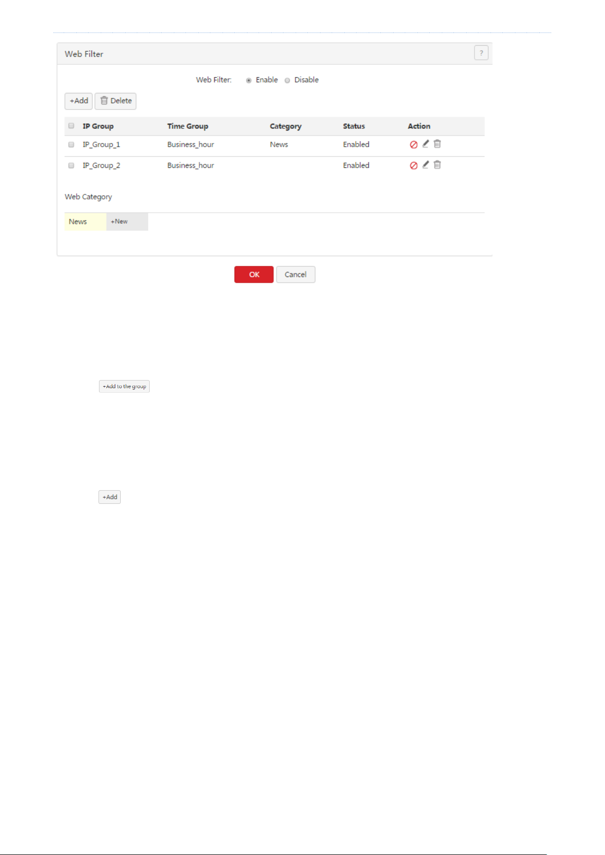
Filter management
V. Add all the news websites inaccessible to the computers.
1. Click News in the Web Category area.
2. Enter the URL of another website inaccessible to the computers and the description of the website.
3. Click .
4. Repeat steps 2 and 3 to add the other websites inaccessible to the computers.
VI. Add a web filtering rule.
1. Choose Filter Management > Web Filter.
2. Click .
3. Set IP Group to the IP address group of the computers allowed to browse only the specified websites.
4. Set Time Group to the time group set in step I.
5. Set Category to News.
6. Click OK.
- 50 -
Page 60

Filter management
Parameter
Description
Smart Load
Balancing
It specifies that the system automatically distributes traffic based on the following rules
through the WAN ports to achieve load balancing:
If the usage of the bandwidths specified by Link Speed preset on the Network >
Internet Setup page is lower than 50%, the router distributes traffic proportionately
according to the ratio between the bandwidths of the ports.
If the usage of the bandwidth on a WAN port specified by Link Speed preset on the
Network > Internet Setup page reaches or exceeds 50%, the router distributes traffic
preferably to the port with more available bandwidth.
5.6 Setting multi-WAN policies
To access the page for setting multi-WAN policies, choose Filter Management > Multi-WAN Policy. See the
following figure.
The following table describes the parameters.
- 51 -
Page 61

Filter management
Parameter
Description
Custom
It enables you to assign WAN ports to source IP addresses as required.
5.6.1 Customizing a multi-WAN policy
Enabling the multi-WAN policy function
1. Choose Filter Management > Multi-WAN Policy.
2. Set Multi-WAN Policy to Custom.
3. Click OK.
Then, you can customize multi-WAN policies.
Setting multi-WAN rules
Adding a rule
(1) Choose Filter Management > Multi-WAN Policy.
(2) Click .
The Add dialog box appears.
The following table describes the parameters.
- 52 -
Page 62

Filter management
Parameter
Description
IP Group
It specifies the referenced IP address group that indicates the users to which a rule is
applicable.
IP address groups must be configured in advance on the Filter Management > IP Group &
Time Group page.
WAN
It specifies the WAN port used for transmitting data traffic of a specified IP address group.
(3) Set the parameters and click OK.
The Multi-WAN Policy page appears, showing the added rule. See the following figure.
Modifying a rule
1. Choose Filter Management > Multi-WAN Policy.
2. Click corresponding to a rule.
3. Modify the rule.
4. To disable a rule, click corresponding to the rule.
5. To enable a rule, click corresponding to the rule.
Deleting a rule
1. Choose Filter Management > Multi-WAN Policy.
2. Click corresponding to a rule to be deleted.
The rule is deleted.
3. To delete multiple web filtering rules at the same time, select them and click .
- 53 -
Page 63

Filter management
5.6.2 Example of customizing a multi-WAN policy
Networking requirement
An enterprise has used M50 to set up a LAN. To meet its internet access requirement, the enterprise has set up
two broadband connections with two different ISPs and can now access the internet properly. To achieve load
balancing, the enterprise raises the following LAN requirements:
The computers with IP addresses ranging from 192.168.0.2 to 192.168.0.100 access the Internal through the
fixed-line broadband connection with ISP A.
The computers with IP addresses ranging from 192.168.0.101 to 192.168.0.250 access the Internal through
the mobile broadband connection with ISP B.
You can use the multi-WAN policy function of the router to meet this requirement.
Network topology
Configuration procedure
I. Set an IP address group.
1. Choose Filter Management > IP Group & Time Group.
2. Set the IP address group shown in the following figure.
- 54 -
Page 64

Filter management
II. Customize a multi-WAN policy.
1. Enable multi-WAN policy customization.
(1) Choose Filter Management > Multi-WAN Policy.
(2) Select Custom.
(3) Click OK.
2. Set multi-WAN rules.
(1) Choose Filter Management > Multi-WAN Policy.
(2) Click .
(3) Set the rules shown in the following figure.
- 55 -
Page 65

Bandwidth control
Step
Task
Description
1
Set the bandwidth
of your broadband
connection.
Set it on the Network > Internet Setup page. For details, see Setting up an
internet connection.
2
Enable smart
bandwidth control.
On the Bandwidth Control page, set Control Mode to Smart Bandwidth Control
and click OK.
Chapter 6 Bandwidth control
6.1 Overview
Internet bandwidth is limited and therefore you must control traffic of users to ensure that the bandwidth is
properly used to effectively access resources over the internet.
This chapter describes:
Setting bandwidth control
Example of setting user-defined bandwidth control
6.1.1 Function introduction
M50 supports the following bandwidth control modes:
Smart bandwidth control
In this mode, the router automatically allocate bandwidth to LAN users based on the Link Speed value that you set
on the Network > Internet Setup page.
Before using smart bandwidth control, set Link Speed to the bandwidth of your broadband connection. Otherwise,
smart bandwidth control may not be accurate.
User-define bandwidth control
In this mode, manually set bandwidth control rules based on the actual environment. User-defined bandwidth
control allows you to set upload bandwidth and download bandwidth shared among the users in IP address
groups or exclusive to specific users in a period. It also allows you to specify the maximum number of concurrent
sessions per user device. Comparatively, user-define bandwidth control is more flexible than smart bandwidth
control, while the latter is easier to use.
6.1.2 Configuration instruction
Smart bandwidth control
- 56 -
Page 66

Bandwidth control
Step
Task
Description
1
Set a time group.
When a user-defined bandwidth control rule is set, a time group is required. Set the
time group on the Filter Management > IP Group & Time Group page.
2
Set an IP address
group.
When a user-defined bandwidth control rule is set, an IP address group is required.
Set the IP address group on the Filter Management > IP Group & Time Group page.
3
Set a
user-defined
bandwidth
control rule.
Set a rule on the Bandwidth Control page.
User-defined bandwidth control
6.2 Setting bandwidth control
To access the page for setting bandwidth control, choose Bandwidth Control. See the following figure. This
section describes how to set user-defined bandwidth control.
6.2.1 Enabling user-defined bandwidth control
1. Choose Bandwidth Control.
2. Set Control Mode to Custom.
3. Click OK.
Then, you can set user-defined bandwidth control rules.
- 57 -
Page 67

Bandwidth control
Parameter
Description
IP Group
It specifies a referenced IP group that indicates the users to which a rule is
applicable.
6.2.2 Setting user-defined bandwidth control rules
Adding a rule
1. Choose Bandwidth Control.
2. Click .
The Add dialog box appears.
The following table describes the parameters.
- 58 -
Page 68

Bandwidth control
Parameter
Description
IP address groups must be configured in advance on the Filter Management > IP
Group & Time Group page.
Time Group
It specifies a referenced time group that indicates the validity period of a rule.
Time groups must be configured in advance on the Filter Management > IP Group &
Time Group page.
Concurrent Session Per
Device
It specifies the maximum number of connections allowed for each user device within
the IP address group. In normal cases, the value 300 is recommended.
Mode
It specifies the bandwidth control mode. The options include:
Shared: In this mode, all the users in specified IP address groups share the
specified upload bandwidth and download bandwidth. The available bandwidth
may differ across the users.
Exclusive: In this mode, the same upload bandwidth and download bandwidth
is allocated to the users in specified IP address groups.
Upload
Upload specifies the upload bandwidth, while Download specifies the download
bandwidth.
Download
3. Set the parameters and click OK.
The Bandwidth Control page appears, showing the added rule. See the following figure.
Modifying a rule
1. Choose Bandwidth Control.
2. Click corresponding to a bandwidth control rule.
3. Modify the rule.
4. To disable a rule, click corresponding to the rule.
- 59 -
Page 69

Bandwidth control
5. To enable a rule, click corresponding to the rule.
Deleting a rule
1. Choose Bandwidth Control.
2. Click corresponding to a rule to be deleted.
The rule is deleted.
3. To delete multiple bandwidth control rules at the same time, select them and click .
6.2.3 Setting bandwidth control parameters for
non-specified user devices
When user-defined bandwidth control is used, you can set bandwidth control parameters for non-specified user
devices, which indicate the user devices whose IP addresses are not covered by bandwidth control rules and user
devices covered by disabled bandwidth control rules.
If you do not select Defaults for unlimited host, the bandwidth and maximum number of concurrent sessions are
not limited.
Set the parameters and click OK.
6.3 Example of setting user-defined bandwidth
control
Networking requirement
An enterprise uses M50 to set up a LAN to address the following requirement:
During business hours (08:00 to 18:00 every weekday), each computer with an IP address ranging from
192.168.0.2 to 192.168.0.100 is allocated 1 Mbps upload and download bandwidth, while the bandwidth
allocated to the computers with an IP address ranging from 192.168.0.101 to 192.168.0.254 is not limited.
You can use the user-defined bandwidth control function of the router to meet this requirement. Assume that the
maximum number of sessions for user device is 300.
Configuration procedure
I. Set a time group.
- 60 -
Page 70

Bandwidth control
1. Choose Filter Management > IP Group & Time Group.
2. Set the time group shown in the following figure.
II. Set an IP address group.
1. Choose Filter Management > IP Group & Time Group.
2. Set the IP address group shown in the following figure.
To allow the other computers with IP addresses ranging from 192.168.0.101 to 192.168.0.254 to access the
internet, add another IP address group to include these IP addresses. See the following figure.
III. Enabling user-defined bandwidth control.
1. On the Bandwidth Control page, select Custom.
2. Click OK.
- 61 -
Page 71

Bandwidth control
IV. Set a user-defined bandwidth control rule.
1. On the Bandwidth Control page, click .
2. Create a rule shown in the following figure (1 Mbps = 128 KB/s).
- 62 -
Page 72

VPN
Chapter 7 VPN
7.1 Overview
A Virtual Private Network (VPN) is a dedicated network set up on a public network (usually the internet). A VPN is
a logically network without physical connections. Using the VPN technology, you can enable your branch
employees to remotely share resources and access your HQ LAN, and meanwhile ensure that the resources are
not accessible to other public network users.
This chapter describes:
Configuring a VPN
Example of configuring a VPN
7.1.1 Network topology
The following figure shows the typical VPN network topology.
7.1.2 VPN types
M50 supports PPTP, L2TP, and IPSec VPNs.
PPTP/L2TP
The Point to Point Tunneling Protocol (PPTP) and Layer 2 Tunneling Protocol (L2TP) are layer-2 VPN tunnel
protocols and the Point to Point Protocol (PPP) is used to encapsulate and add additional headers to data.
M50 can functions as a PPTP/L2TP server or client.
IPSec
IP Security (IPSec) is a protocol suite for transmitting data over the internet in a secure and encrypted manner.
7.1.3 IPSec-related concepts
Security gateway
It refers to a gateway (secure and encrypted router) with the IPSec functionality. IPSec is used to protect data
exchanged between such gateways from tampering and peeping.
IPSec peer
The two IPSec terminals are called IPSec peers. The two peers (security gateways) can securely exchange data only
- 63 -
Page 73

VPN
after a Security Association (SA) is set up between them.
SA
SA specifies some elements of the peers, such as the base protocol (AH, ESP, or both), encapsulation mode
(transport or tunnel), cryptographic algorithm (DES, 3DES, or AES), shared key for data protection in specified
flows, and life cycle of the key. SA has the following features:
- A triplet {SPI, Destination IP address, Security protocol identifier} is used as a unique ID.
- An SA specifies the protocol, algorithm, and key for processing packets.
- Each IPsec SA is unidirectional with a life cycle.
- An SA can be created manually or generated automatically using internet Key Exchange (IKE).
7.2 Configuring a VPN
7.2.1 Configuring M50 as a PPTP/L2TP client
M50 can function as a PPTP/L2TP client to connect to a PPTP/L2TP server. For example, if your branch needs to
exchange information with your HQ in a simple and secure manner, you can set up a PPTP/L2TP server at the HQ
and configure the egress router of your branch as a PPTP/L2TP client to connect to the server.
To access the page for configuring M50 as a PPTP/L2TP client, choose VPN > PPTP/L2TP Client. See the following
figure.
1. Set PPTP/L2TP Client to Enable.
2. Set the parameters.
3. Click OK.
- 64 -
Page 74

VPN
Parameter
Description
PPTP/L2TP Client
It specifies whether the PPTP/L2TP client function is enabled. If this parameter is set to
Enabled, M50 functions as a PPTP/L2TP VPN client.
Type
It specifies the client type of the router. The router supports the following types:
PPTP Client: Select this option if the VPN server to be connected is a PPTP server.
L2TP Client: Select this option if the VPN server to be connected is an L2TP server.
WAN
It specifies the WAN port of the router for setting up a VPN connection.
Server IP
Address/Domain
Name
It specifies the IP address or domain name of the VPN server to be connected. Generally,
it refers to the IP address or domain name of the WAN port of the peer VPN router that
functions as the PPTP/L2TP server.
Username
Username specifies the user name of a PPTP/L2TP account. Password specifies the
password for the account. The user name and password are assigned by the VPN server
to be connected.
Password
Encryption
It specifies whether to enable 128-bit data encryption. The value of this parameter must
be consistent with that of the server. Otherwise, the client is unable to communicate
with the server.
Only PPTP VPNs support this parameter.
The following table describes the parameters.
- 65 -
Page 75

VPN
VPN Proxy
It specifies whether the computers on your LAN access the internet through the router
of the PPTP/L2TP server.
Remote LAN
It specifies the network segment of the LAN of the PPTP/L2TP server.
Remote Subnet
Mask
It specifies the subnet mask of the LAN of the PPTP/L2TP server.
Status
It specifies the current connection status of the VPN client.
7.2.2 Configuring M50 as a PPTP/L2TP server
M50 can function as a PPTP/L2TP server to connect to PPTP/L2TP clients. For example, if your branch needs to
exchange information with your HQ in a simple and secure manner, you can set up a PPTP/L2TP server at the HQ
and configure the egress router of your branch as a PPTP/L2TP client to connect to the server.
To access the page for configuring M50 as a PPTP/L2TP server, choose VPN > PPTP/L2TP Server. See the following
figure.
To configure M50 as a PPTP/L2TP server, enable the PPTP/L2TP server function and configure a PPTP/L2TP
account.
Enabling the PPTP/L2TP server function
1. Choose VPN > PPTP/L2TP Server.
2. Set Status to Enable.
3. Set the parameters and click OK.
- 66 -
Page 76

VPN
Parameter
Description
Status
It specifies whether to enable the PPTP/L2TP server function. If this parameter is set to
Enabled, M50 functions as a PPTP/L2TP server.
Type
It specifies the server type of the router. The router supports the following types:
PPTP Server: If this option is selected, the server is accessible only to PPTP clients.
L2TP Server: If this option is selected, the server is accessible only to L2TP clients.
WAN
It specifies the outgoing port of the tunnel between a PPTP/L2TP server and PPTP/L2TP
clients.
Encryption
It specifies whether to enable 128-bit data encryption. The value of this parameter must
be consistent with that of a client. Otherwise, the client is unable to communicate with
the server.
Only PPTP VPNs support this parameter.
IP Address Pool
It specifies the range of IP addresses assigned by the server to the PPTP/L2TP VPN clients
connected to the server.
Max. Connections
It specifies the maximum VPN clients that can be connected to the PPTP/L2TP server at
the same time. The number is fixed at 15.
The following table describes the parameters.
Configuring a PPTP/L2TP account
A PPTP/L2TP account is required when a VPN user accesses M50 that functions as a PPTP/L2TP server.
- 67 -
Page 77

VPN
Parameter
Description
Username
Username specifies the user name used to set up a PPTP/L2TP VPN connection. Password
specifies the password for the user name.
Password
Type
Network: It indicates that a VPN client is a network. If this option is selected, set the
Network and Subnet Mask parameters as well.
Host: It indicates that a VPN client is a computer.
Network
It specifies the LAN network segment of a VPN client in case that the client is a network.
Subnet Mask
It specifies the subnet mask of the LAN of a VPN client in case that the client is a network.
Remark
(Optional)
It specifies the description of a user. This parameter is optional.
Adding a user
1. Choose VPN > PPTP/L2TP Server.
2. Click .
The Add dialog box appears.
The following table describes the parameters.
3. Set the parameters and click OK.
The PPTP/L2TP Server page appears, showing the added user. See the following figure.
- 68 -
Page 78

VPN
Parameter
Description
IPSec
It specifies whether to enable the IPSec function.
WAN
It specifies the local WAN port assigned to the IPSec function. The IP address of the WAN port
must be set as the value of Remote Gateway of the IPSec peer.
Connection
Name
It specifies the name of the IPSec connection to be set up.
Modifying a user
1. Choose VPN > PPTP/L2TP Server.
2. Click corresponding to a user.
3. Modify the user.
Deleting a user
1. Choose VPN > PPTP/L2TP Server.
2. Click corresponding to a user to be deleted.
The user is deleted.
3. To delete multiple users at the same time, select them and click .
7.2.3 Configuring the IPSec function
To access the page for configuring the IPSec function, choose VPN > IPSec. See the following figure.
The following table describes the parameters.
- 69 -
Page 79

VPN
Tunnel Protocol
It specifies the security service protocol for the IPSec function. M50 supports the following
protocols:
AH: It indicates the Authentication Header (AH) protocol used for verifying data
integrity. If a packet is tampered during transmission, the receiver discards it during data
integrity verification.
ESP: It indicates the Encapsulating Security Payload (ESP) protocol for verifying data
integrity and encrypting data. If a packet processed using this protocol is intercepted
during transmission, it is difficult for the intercepting party to obtain the real
information contained in the packet.
AH+ESP: It indicates both the AH and ESP protocols are used.
Remote
Gateway
It specifies the IP address or domain name of the peer gateway of an IPSec tunnel.
Local
LAN/Mask
It specifies the network segment and subnet mask of the LAN port of the router. For example,
if the IP address of the LAN port of the router is 192.168.0.252 and the subnet mask is
255.255.255.0, set this parameter to 192.168.0.0/24.
Remote
LAN/Mask
It specifies the network segment and subnet mask of the LAN port of the peer gateway, or
the IP address and subnet mask of the peer gateway if the gateway is a mobile device. The
value format is Network segment or IP address of the peer gateway/Subnet mask.
Key
Negotiation
It specifies the key negotiation mode for an IPSec tunnel. The options include:
Auto: It indicates that an SA is set up, maintained, and deleted automatically using IKE.
This reduces configuration complexity and simplifies IPSec usage and management. Such
an SA has a life cycle and is updated regularly, ensuring higher security.
Custom: It indicates that an SA is set up by manually specifying encryption and
authentication algorithms and keys. Such an SA does not have a life cycle, and therefore
it remains valid unless being manually deleted, leading to a security risks. Generally, this
mode is used only for commissioning.
Key negotiation mode – Auto
In this mode, the IPSec peers must use information shared between them to encrypt and decrypt data to ensure
data confidentiality. Therefore, at the beginning of communication, the peers must negotiate a security key, which
is performed by IKE, a combination of ISAKMP, Oakley, and SKEME protocols. The protocols are described as
follows:
ISAKMP: Short for internet Security Association and Key Management Protocol, ISAKMP provides a
framework for key exchange and SA negotiation.
Oakley: It describes a key exchange mechanism.
SKEME: It describes a key exchange mechanism other than that described by the Oakley protocol.
IKE-based negotiation is divided into the following periods:
Period 1: The peers negotiate security proposals such as authentication and encryption algorithms for
- 70 -
Page 80

VPN
Parameter
Description
Authentication
Type
It specifies a shared key negotiated by the IPSec peers by a certain means. The value Shared
key is displayed.
Pre-shared Key
It specifies a pre-shared key used for negotiation. The key consists of a maximum of 128
characters and must be the same as that specified on the peer gateway.
Advanced…
It is a link for you to view advanced parameters for automatic key negotiation. When you
click this link, the parameters shown in the following figure appears.
communication, and set up an ISAKMP SA for exchanging more information in period 2 in a secure manner.
Period 2: The ISAKMP SA set up in period 1 is used as an IPSec security protocol negotiation parameter to set
up an IPSec SA for protecting data exchanged between the peers.
The following figure shows the parameters displayed when Key Negotiation is set to Auto.
The following table describes the parameters.
- 71 -
Page 81

VPN
Parameter
Description
Mode
It specifies a packet exchange mode for IKE in period. The exchanged mode must be
the same as that specified on the peer. The options include:
MAIN: In this mode, the two peers exchange many packets under identity
protection, and therefore this mode is more suitable for scenarios where
high-level identity protection is required.
AGGRESSIVE: In this mode, the two peers exchange only a few packets without
identity protection. This mode features quick negotiation and therefore is more
suitable for scenarios where high-level identity protection is not required.
Encryption Algorithm
It specifies an IKE session encryption algorithm. M50 supports the following
encryption algorithms:
DES/3DES: The Data Encryption Standard (DES) uses a 56-bit key to encrypt 64-bit
data and implements parity check on the last 8 bits of the 64 bits. 3DES indicates
triple DES, where three 56-bit keys are used to encrypt data.
AES-128/AES-192/AES-256: The Advanced Encryption Standard
(AES)-128/192/256 indicates that a key consisting of 128/192/256 bits is used to
encrypt data.
Integrity Verification
It specifies an IKE session verification algorithm. M50 supports the following
The following table describes the parameters.
- 72 -
Page 82

VPN
Parameter
Description
Algorithm
verification algorithms:
MD5: Short for Message Digest 5, MD5 generate a 128-bit digest of a message to
prevent message tampering.
SHA1: Short for Secure Hash Algorithm 1, SHA1 generates a 160-bit digest of a
message to prevent message tampering. Therefore, SHA1 offers better security
than MD5.
Diffie-Hellman Group
It specifies a Diffie-Hellman group for generating an IKE tunnel key.
Key Life Cycle
It specifies the validity period of an IPSec SA.
PFS
It specifies whether to enable the Perfect Forward Secrecy (PFS) feature, which
generates a new key for IKE in period 2. This new key is not related to the key
generated in period 1. In this case, the key generated in period 2 ensures data security
when the key generated in period 1 is cracked.
If this feature is disabled, the new key is generated in period 2 based on the key
generated in period 1. In this case, when the key generated in period 1 is cracked, the
new key for ensuring data security is at stake, seriously threatening the security of
communication between the two peers.
Key negotiation mode – Custom
The following figure shows the parameters available in this mode. (Tunnel Protocol is set to AH+ESP.)
The following table describes the parameters.
- 73 -
Page 83

VPN
Parameter
Description
ESP Encryption
Algorithm
It specifies the ESP encryption algorithm required in case that Tunnel Protocol is set to ESP.
M50 supports the following encryption algorithms:
DES/3DES: DES uses a 56-bit key to encrypt 64-bit data and implements parity check on
the last 8 bits of the 64 bits. 3DES indicates triple DES, where three 56-bit keys are used
to encrypt data.
AES-128/AES-192/AES-256: AES-128/192/256 indicates that a key consisting of
128/192/256 bits is used to encrypt data.
ESP Encryption
Key
It specifies an ESP encryption key, which must be adopted by the two IPSec peers.
ESP
Authentication
Algorithm or
AH
Authentication
Algorithm
ESP Authentication Algorithm is used in case that Tunnel Protocol is set to ESP. AH
Authentication Algorithm is used in case that Tunnel Protocol is set to AH. M50 provides the
following authentication algorithm options:
NONE: If this option is selected, no ESP authentication key is required.
MD5: If this option is selected, a 128-bit digest of a message is generated to prevent
tampering.
SHA1: If this option is selected, a 160-bit digest of a message is generated to prevent
tampering. SHA1 offers better security than MD5.
ESP
Authentication
Key or AH
Authentication
Key
ESP Authentication Key is used in case that Tunnel Protocol is set to ESP. AH Authentication
Key is used in case that Tunnel Protocol is set to AH.
The IPSec peers must adopt the same authentication key.
ESP Outgoing
SPI or AH
Outgoing SPI
It specifies an outgoing Security Parameter Index (SPI).
An SPI, the peer gateway address of a tunnel, and a protocol type together identify an IPSec
SA. The outgoing SPI specified here must be the same as the incoming SPI of the peer.
ESP Incoming
SPI or AH
Incoming SPI
An SPI, the peer gateway address of a tunnel, and a protocol type together identify an IPSec
SA. The incoming SPI specified here must be the same as the outgoing SPI of the peer.
7.3 Example of configuring a VPN
7.3.1 Example of configuring a PPTP/L2TP VPN
Networking requirement
An enterprise has used M50 to set up a LAN and access the internet. Employees of its branch must be allowed to
access, through the internet, the HQ’s resources over the HQ LAN in a secure manner, including internal materials
as well as the OA, ERP, CRM, and project management systems.
- 74 -
Page 84

VPN
You can set up a PPTP/L2TP VPN using the router to meet this requirement. This example describes the method to
set up a PPTP VPN. You can set up an L2TP VPN using the same method.
Network topology
Configuration procedure
Configure M50_1 as a VPN server and M50_2 as a VPN client as follows:
I. Configure M50_1.
1. Enable the PPTP server function.
(1) On M50_1, choose VPN > PPTP/L2TP Server.
(2) Set Status to Enable.
(3) Set Type to the type of the VPN server, which is PPTP Server in this example.
(4) Set WAN to the outgoing port of the VPN server for setting up a tunnel with the VPN client, which is WAN0 in
this example.
(5) Set Encryption to specify whether to enable data encryption. The PPTP server and client must use the same
setting.
(6) Click OK.
- 75 -
Page 85

VPN
2. Configure a PPTP/L2TP user.
(1) On M50_1, choose VPN > PPTP/L2TP Server.
(2) Click .
(3) Set Username to the user name used to connect the VPN client to the VPN server, which is Branch_1 in this
example.
(4) Set Password to the password for the user name, which is Branch_1 in this example.
(5) Set Type to Network.
(6) Set Network to the LAN IP address of the VPN client, which is 192.168.1.0 in this example.
(7) Set Subnet Mask to 255.255.255.0.
(8) Set Remark (Optional) to the description of the user, which is Branch_1 in this example.
- 76 -
Page 86

VPN
(9) Click OK.
II. Configure M50_2.
(1) On M50_2, choose VPN > PPTP/L2TP Client.
(2) Set PPTP/L2TP Client to Enable.
(3) Set Type to the value matching the VPN server, which is PPTP Client in this example.
(4) Set WAN to the outgoing port of the VPN client for setting up a tunnel with the VPN server, which is WAN0 in
this example.
(5) Set Server IP Address/Domain Name to the IP address of the outgoing port of the VPN server, which is
202.105.11.22 in this example.
(6) Set Username and Password to the user name and password assigned by the VPN server, which are
Branch_1 in this example.
(7) Set Encryption to Enable. This setting must be the same as that on the VPN server.
(8) Set VPN Proxy to Disable.
(9) Set Remote LAN to the LAN network segment of the VPN server, which is 192.168.0.0 in this example.
(10) Set Remote Subnet Mask to the LAN subnet mask of the VPN server, which is 255.255.255.0 in this example.
(11) Click OK.
- 77 -
Page 87

VPN
Verification
1. On M50_2, choose VPN > PPTP/L2TP Client.
2. Verify that Status is Connected and an IP address has been obtained.
See the following figure.
- 78 -
Page 88

VPN
After the preceding configuration, employees at the branch and HQ can remotely access resources on the branch
and HQ LANs through the internet in a secure manner.
7.3.2 Example of configuring an IPSec VPN
Networking requirement
An enterprise has used M50 to set up a LAN and access the internet. Employees of its branch must be allowed to
access, through the internet, the HQ’s resources over the HQ LAN in a secure manner, including internal materials
as well as the OA, ERP, CRM, and project management systems.
You can set up an IPSec VPN using the router to meet this requirement.
- 79 -
Page 89

VPN
Network topology
Configuration procedure
Assume that the two routers share the following basic IPSec tunnel information:
Key negotiation mode: auto
Pre-shared key: 12345678
I. Configure M50_1.
(1) On M50_1, choose VPN > IPsec.
(2) Click .
(3) Set IPSec to Enable.
(4) Set WAN to the WAN port bound to the IPSec tunnel, which is WAN0 in this example.
(5) Set Connection Name to the name of the IPSec tunnel, which is IPSec_1 in this example.
(6) Set Remote Gateway (Domain Name) to the IP address of the M50_2 WAN port bound to the IPSec tunnel,
which is 202.105.88.77 in this example.
(7) Set Local LAN/Mask to the LAN network segment and subnet mask of M50_1, which is 192.168.0.0/24 in this
example.
(8) Set Remote LAN/Mask to the LAN network segment and subnet mask of M50_2, which is 192.168.1.0/24 in
this example.
(9) Set Pre-shared Key to 12345678.
- 80 -
Page 90

VPN
(10) Click OK.
II. Configure M50_2.
(1) On M50_2, choose VPN > IPsec.
(2) Click .
The Add page appears. See the following figure.
- 81 -
Page 91

VPN
(3) Follow the M50_1 configuration procedure to set the parameters.
Verification
1. Log in to the routers, choose System > Live Users.
2. Verify that IPSec displays the number of connections and related connection information.
After the preceding configuration, employees at the branch and HQ can remotely access resources on the branch
and HQ LANs through the internet in a secure manner.
Note
If advanced settings of the IPSec tunnel are required, apply the same settings to both routers.
If Key Negotiation is set to Custom, the same encryption algorithm encryption key, and authentication
algorithm must be applied to the IPSec peers. The outgoing SPI of M50_1 must be the same as the incoming
SPI of M50_2, and the incoming SPI of M50_1 must be the same as the outgoing SPI of M50_2.
- 82 -
Page 92

Security
Chapter 8 Security
This chapter describes:
Binding an IP address with a MAC address
Protecting against attacks
8.1 Overview
The Security module of M50 allows you to bind IP addresses with MAC addresses and implement attack
protection.
IP-MAC binding
You can use this function to bind IP addresses with MAC addresses for the computers on your LAN. After this
function is enabled, only the computers on the Binging List can access the internet. This can effectively prevents
unauthorized usage of LAN IP addresses, improving the network security.
M50 supports both manual and dynamic binding modes, which are described as follows:
Manual binding: In this mode, you need to create a binding list. Therefore, the administrator needs to know
the MAC addresses of all the computers in your LAN and mapping between the IP addresses and MAC
addresses of the computers.
Dynamic binding: In this mode, Dynamic Binding on the Security > IP-MAC Binding page displays the
mapping between the IP address and MAC address of a computer after the computer connects to the router.
You only need to click Bind corresponding to the mapping on the page to bind the IP address with the MAC
address.
Attack protection
M50 can implement ARP attack defense, DDoS attack defense, IP attack defense, and WAN ping attack defense,
which are described as follows:
ARP attack defense: This function protects against ARP spoofing and ARP broadcast.
DDoS attack defense: This function protects against various DDoS attacks, including ICMP flood, UDP flood,
and SYN flood attacks, which are used to consume resources of a target system to disable the system to
properly provide services.
IP attack defense: This function blocks the data packets with special IP options as configured. The IP options
include the IP timestamp option, IP security option, IP stream option, IP record route option, IP loose source
route option, and invalid IP option.
WAN ping attack defense: This function enables the router to ignore ping requests when a computer on a
WAN pings the WAN port IP address of the router, so as to prevent exposing the router and protect against
ping attacks.
After an attack defense function is enabled, the router logs the attack time, attack type, attack count, and attacker
IP address and MAC address on the System > Defense Logs page when an attack corresponding to the defense
function is carried out. This log helps you maintain network security.
- 83 -
Page 93

Security
Parameter
Description
IP-MAC Binding
It specifies whether to enable the IP-MAC binding function. The default option
is Disable.
After the function is enabled, only the computers listed on the Binding List
can access the internet.
Binding List
+Add
It is used to manually bind IP addresses and MAC addresses.
Unbind
It is used to unbind IP addresses from MAC addresses.
8.2 Binding an IP address with a MAC address
To access the page for binding an IP address with a MAC address, choose Security > IP-MAC Binding. See the
following figure.
8.2.1 Enabling the IP-MAC binding function
To enable the IP-MAC binding function, set IP-MAC Binding to Enable and click OK. Then, you can bind IP
addresses with MAC addresses.
The following table describes the parameters.
- 84 -
Page 94

Security
Parameter
Description
IP Address
IP Address specifies the IP addresses bound with MAC addresses. MAC
Address specifies the MAC addresses bound with IP addresses.
MAC Address
Remark
It specifies the description of a binding between an IP address and a MAC
address. In a binding entry, this parameter is blank if no description is
specified when the entry is created.
Action
It specifies the operations that can be performed on binding entries. To
modify an entry, click corresponding to the entry. To delete an entry, click
corresponding to the entry.
Dynamic
Binding
Bind
It is used to add a mapping between an IP address and a MAC address to the
binding list. Such mappings are displayed on the dynamic binding list after
computers on your LAN connect to the router.
Bind All
It is used to add all the mappings between IP addresses and MAC addresses
from the dynamic binding list to the binding list.
IP Address
IP Address specifies the IP addresses of the computers connected to the
router. MAC Address specifies the MAC addresses of the computers
connected to the router.
MAC Address
Action
It specifies a link that can be used on add the mapping between an IP address
and a MAC address corresponding to the link to the binding list.
8.2.2 Configuring an IP-MAC binding entry
Manually adding an entry
1. Choose Security > IP-MAC Binding.
2. Click .
3. Set the parameters.
- 85 -
Page 95

Security
4. Click OK.
The IP-MAC Binding page appears, showing the added IP-MAC binding entry.
Modifying an entry
1. Choose Security > IP-MAC Binding.
2. Click corresponding to an entry to be modify.
3. Modify the entry.
Deleting an entry
1. Choose Security > IP-MAC Binding.
2. Click corresponding to an entry to be deleted.
The entry is deleted.
3. To delete multiple entries at the same time, select the entries and click .
Automatically adding an entry
1. Choose Security > IP-MAC Binding.
2. Add entries in the dynamic binding list to the binding list.
8.3 Protecting against attacks
To access the page for protecting against attacks, choose Security > Firewall. See the following figure.
- 86 -
Page 96
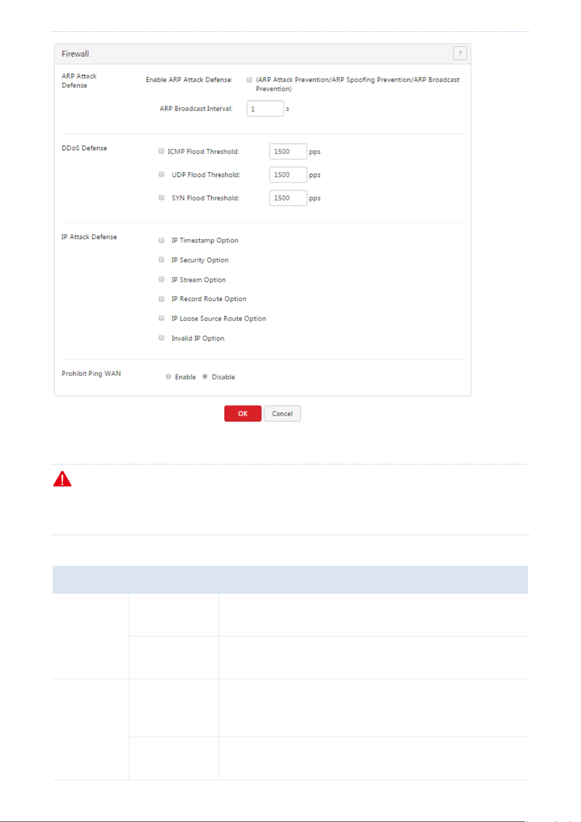
Security
Parameter
Description
ARP Attack
Defense
Enable ARP Attack
Defense
It specifies whether the ARP attack defense function, which protects
against ARP attacks, ARP spoofing, and ARP broadcast, is enabled.
ARP Broadcast
Interval
It specifies the interval at which the router sends ARP broadcast
packets.
DDoS Defense
ICMP Flood
Threshold
It specifies the maximum number of incoming ICMP packets allowed in
one second. If the threshold is exceeded, it is inferred that the router is
under ICMP Flood attack.
UDP Flood
Threshold
It specifies the maximum number of incoming UDP packets allowed in
one second. If the threshold is exceeded, it is inferred that the router is
After enabling attack protection, you can view attack information on the System > Defense Logs page.
Note
Some data packets detected by the attack protection functions, such as some data packets used for network tests,
are not attack packets. Therefore, enable the functions only when necessary.
The following table describes the parameters.
- 87 -
Page 97

Security
Parameter
Description
under UDP Flood attack.
SYN Flood
Threshold
It specifies the maximum number of incoming TCP SYN packets allowed
in one second. If the threshold is exceeded, it is inferred that the router
is under SYN Flood attack.
IP Attack
Defense
IP Timestamp
Option
It enables the router to block IP packets with the Internet Timestamp
option.
IP Security Option
It enables the router to block IP packets with the Security option.
IP Stream Option
It enables the router to block IP packets with the Stream ID option.
IP Record Route
Option
It enables the router to block IP packets with the Record Route option.
IP Loose Source
Route Option
It enables the router to block IP packets with the Loose Source Route
option.
Invalid IP Option
It enables the router to block IP packets with integrity or correctness
problems.
Prohibit Ping WAN
It specifies whether to enable the WAN ping attack defense function.
The default option is Disable.
After this function is enabled, devices on a WAN cannot ping the IP
address of the WAN port of the router.
- 88 -
Page 98

AC management
Chapter 9 AC management
This chapter describes:
Configuring wireless settings
Configuring advanced settings
Managing APs
Viewing user status
Updating user information
9.1 Overview
M50 can work as an AC to manage a maximum of 16 IP-COM APs. The following figure shows the network
topology where M50 functions as an AC to manage APs.
The AC management function of M50 allows you to configure wireless settings, Configuring advanced settings,
Managing APs, Viewing user status.
Wireless Settings: This module allows you to enable or disable the AC management function of the router
and configure SSID-related parameters for the APs on your LAN in a centralized manner. The parameters
allow you to specify SSIDs, SSID status, frequencies, maximum number of users, VLAN IDs, authentication
types, and passwords, specify whether to hide specific SSIDs, and so on.
Advanced Settings: This module allows you to configure RF settings and global settings for all the APs on you
LAN after the AC management function is enabled.
AP Management: This module allows you to view information about APs on your LAN after the AC
management function is enabled. It also allows you to export, reboot, upgrade, reset, delete, and refresh APs
- 89 -
Page 99

AC management
in batches.
User Status: This module allows you to view, after the AC management function is enabled, information
about users connected to the APs managed by the router.
9.2 Configuring wireless settings
To access the page for configuring wireless settings, choose AC Management > Wireless Settings. See the
following figure.
9.2.1 Enabling the AC management function
1. Choose AC Management > Wireless Settings.
2. Set AC Management to Enable.
Then, you can manage all the APs on your LAN in a centralized manner. To view the APs being managed by the
router, choose AC Management > AP Management.
Note
You can use the functions of the AC management module only after setting AC Management to Enable.
9.2.2 Delivering wireless network policies to APs
1. Choose AC Management > Wireless Settings.
2. Configure SSID-related policies for APs managed by the router.
3. Click OK.
Note
The AC management function allows you to set various AP parameters. Some parameters not supported by APs
can be delivered but do not take effect. For example, if you use the AC management function to deliver the 5 GHz
frequency parameter to APs that do not support the 5 GHz frequency, the parameter can be delivered successfully
to the APs but the APs are not switched to the 5 GHz frequency.
- 90 -
Page 100

AC management
Parameter
Description
Item
It specifies the serial number of a wireless network policy. SNs 1 to 4 correspond to SSIDs 1 to
4 for the 2.4 GHz or 5 GHz frequency respectively, while SNs 5 to 8 correspond to SSIDs 5 to 8
for the 2.4 GHz frequency respectively.
The first 4 policies can contain SSID-related parameters applicable to the 2.4 GHz or 5 GHz
frequency or both of them. The last 4 policies can contain only the SSID-related parameters
applicable to the 2.4 GHz frequency.
Status
It specifies whether a wireless network policy and its corresponding SSID are enabled. By
default, wireless network policy 1 is enabled and the other wireless network policies are
disabled.
Note
Disabling wireless network policy 1 may disable the wireless network function of APs.
Therefore, it is recommended that you leave wireless network policy 1 enabled. If you disable
wireless network policy 1 and then enable it again, the wireless network function of APs may
not be enabled as well. In that case, you can enable it on the AC Management > Advanced
The following table describes the parameters.
- 91 -
 Loading...