

Page 1

User Guide
Gigabit Cloud Managed Switch
Page 2

i
Copyright statement
Copyright © 2021 IP-COM Networks Co., Ltd. All rights reserved.
is the registered trademark of IP-COM Networks Co., Ltd. Other brand and
product names mentioned herein are trademarks or registered trademarks of their respective
holders. Copyright of the whole product as integration, including its accessories and software,
belongs to IP-COM Networks Co., Ltd. No part of this publication can be reproduced,
transmitted, transcribed, stored in a retrieval system, or translated into any language in any
form or by any means without the prior written permission of IP-COM Networks Co., Ltd.
Disclaimer
Pictures, images and product specifications herein are for references only. To improve internal
design, operational function, and/or reliability, IP-COM reserves the right to make changes to
the products described in this document without obligation to notify any person or
organization of such revisions or changes. IP-COM does not assume any liability that may occur
due to the use or application of the product or circuit layout(s) described herein. Every effort
has been made in the preparation of this document to ensure accuracy of the contents, but all
statements, information and recommendations in this document do not constitute a warranty
of any kind, express or implied.
Page 3
ii
Preface
Thank you for choosing IP-COM! This user guide helps you configure, manage and maintain the
product.
Conventions
This user guide is applicable to the following switches. For product features and software
screenshots, please refer to the actual product. G3326P-24-410W is used for illustration if
there is no other specification.
Model
Product Name
G3310P-8-150W
8GE+2SFP Cloud Managed PoE Switch
G3318P-16-250W
16GE+2SFP Cloud Managed PoE Switch
G3326P-24-410W
24GE+2SFP Cloud Managed PoE Switch
G3310F
8GE+2SFP Cloud Managed Switch
Tip
Functions of different models may differ. Please refer to the actual web UI of the product.
The typographical elements that may be found in this document are defined as follows.
Item
Presentation
Example
Cascading menus
>
Choose System > Live Users.
Parameter and
value
Bold
Set User Name to Tom.
Variable
Italic
Format: XX:XX:XX:XX:XX:XX
UI control
Bold
On the Policy page, click the OK button.
The symbols that may be found in this document are defined as follows.
Item
Meaning
This format is used to highlight information of importance or special interest.
Ignoring this type of note may result in ineffective configurations, loss of data or
damage to device.
Note
Page 4
iii
Item
Meaning
This format is used to highlight a procedure that will save time or resources.
For more documents
Go to our website at www.ip-com.com.cn and search for the latest documents for this product.
Product materials
Document
Description
Data sheet
It introduces the basic information of the device, including product overview,
selling points, and specifications.
Quick installation
guide
It introduces how to set up the device quickly for internet access, the descriptions
of LED indicators, ports, and buttons, FAQ, statement information, and so on.
User guide
It introduces how to set up more functions of the device for more requirements,
including all functions on the web UI of the device.
Technical support
If you need more help, contact us using any of the following means. We will be glad to assist
you as soon as possible.
(86 755) 2765 3089
www.ip-com.com.cn
Revision history
IP-COM is constantly searching for ways to improve its products and documentation. The
following table indicates any changes that might have been made since the user guide was
released.
Version
Date
Description
V1.0
2021-11-18
Original publication
Tip
Page 5

iv
Contents
1 Web login .................................................................................................................................... 1
1.1 Login ............................................................................................................................................. 1
1.2 Logout ........................................................................................................................................... 3
2 Web UI introduction .................................................................................................................... 4
2.1 Web layout.................................................................................................................................... 4
2.2 Commonly used buttons .............................................................................................................. 5
3 System management ................................................................................................................... 6
3.1 System info ................................................................................................................................... 6
3.2 User management ........................................................................................................................ 8
3.3 Restore to factory settings ............................................................................................................ 9
3.3.1 Software reset ........................................................................................................................ 9
3.3.2 Hardware reset ...................................................................................................................... 9
3.4 Reboot ........................................................................................................................................ 10
3.5 Firmware upgrade ...................................................................................................................... 11
4 Port management...................................................................................................................... 12
4.1 Port configuration ....................................................................................................................... 12
4.2 Port mirroring ............................................................................................................................. 14
4.3 Port statistics .............................................................................................................................. 15
5 Link aggregation ........................................................................................................................ 16
6 Network extension .................................................................................................................... 18
7 PoE management ...................................................................................................................... 19
8 VLAN management .................................................................................................................... 21
8.1 Overview ..................................................................................................................................... 21
8.2 Configure 802.1Q VLAN .............................................................................................................. 22
8.2.1 Create VLAN rules ................................................................................................................ 22
8.2.2 Configure VLAN port members ............................................................................................ 22
8.3 Example of 802.1Q VLAN configuration ..................................................................................... 24
9 Device management .................................................................................................................. 27
9.1 MAC binding ............................................................................................................................... 27
9.1.1 Overview .............................................................................................................................. 27
9.1.2 Configure MAC binding ........................................................................................................ 27
9.1.3 Example of configuring MAC binding ................................................................................... 28
9.2 QoS ............................................................................................................................................. 30
Page 6

v
9.2.1 Overview .............................................................................................................................. 30
9.2.2 Configure QoS ...................................................................................................................... 31
9.3 STP .............................................................................................................................................. 33
9.3.1 Overview .............................................................................................................................. 33
9.3.2 STP global settings ............................................................................................................... 37
9.3.3 STP port configuration ......................................................................................................... 39
9.4 Diagnosis ..................................................................................................................................... 41
9.5 IMS cloud management ............................................................................................................. 42
9.5.1 Overview .............................................................................................................................. 42
9.5.2 Management on IP-COM IMS Cloud .................................................................................... 43
9.5.3 Management on IP-COM IMS app ....................................................................................... 44
10 Configuration .......................................................................................................................... 48
10.1 Back up system configurations ................................................................................................. 48
10.2 Import configuration file .......................................................................................................... 48
Appendix ...................................................................................................................................... 50
Acronyms and Abbreviations ............................................................................................................ 50
Configure the switch to access the internet ..................................................................................... 51
Page 7
Version 1.0
Chapter 1 Web login 1
1 Web login
1.1 Login
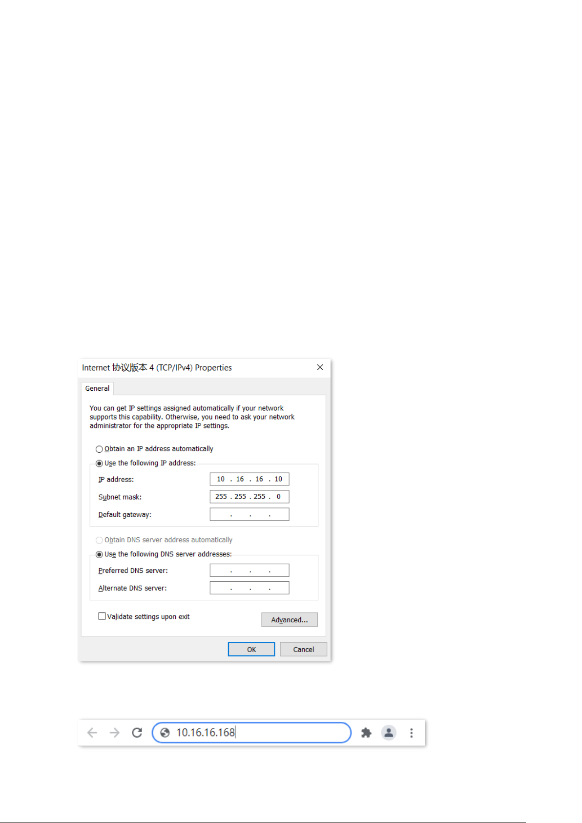
1. Connect the computer to one of the RJ45 ports of the switch using an Ethernet cable.
2. Set the IP address of Ethernet (or Local Area Connection) of the computer to an unused one
belonging to the same network segment of the IP address of the switch.
For example, the default IP address of the switch is 10.16.16.168, you can set the IP address of
the computer to 10.16.16.X (X is an unused number ranging from 2 to 254 except 168), and
subnet mask to 255.255.255.0.
3. Start a browser (such as Chrome) and enter the IP address of the switch (default:
10.16.16.168) in the address bar to access the login page.
Page 8
Version 1.0
Chapter 1 Web login 2
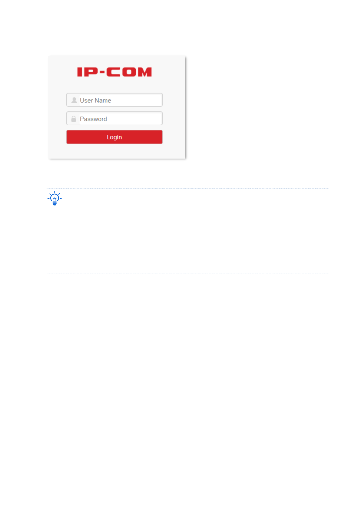
4. Enter your user name and password (both are admin by default) and click Login.
----End
Tip
If the above page does not appear, try the following solutions:
− Clear the cache of the web browser or try another web browser.
− Check whether another device with the IP address 10.16.16.168 exists in the local network.
− If the problem persists, reset the switch and try again. Reset method: When the SYS LED indicator is
blinking, press down the reset button (RESET) using a sharp item (such as a pin) for about 7 seconds,
and then release it when all LED indicators are solid on. When the SYS LED indicator blinks again, the
switch is reset successfully.
After logging in to the web UI, you can start to configure the switch.
Page 9

Version 1.0
Chapter 1 Web login 3
1.2 Logout
After you log in to the switch’s web UI page, the system will automatically log you out if there
is no operation within five minutes. Alternatively, you can directly click Logout on the upper
right corner to exit the web UI page.
Page 10
2 Web UI introduction
No.
Name
Description
❶
Level-1 navigation bar
The navigation bars and tab pages display the function menu of the
switch. When you select a function in navigation bar, the
configuration of the function appears in the configuration area.
❷
Level-2 navigation bar
❸
Tab page area
❹
Configuration area
This area enables you to view and modify configuration.
Tip
Features and parameters in gray indicate that they are not
available or cannot be changed under the current condition.
❹
2.1 Web layout
The Web UI page can be divided into four parts: level-1 navigation bar, level-2 navigation bar,
tab page area, and the configuration area.
❸
❶
Version 1.0
❷
Chapter 2 Web UI introduction 4
Page 11

Version 1.0
Chapter 2 Web UI introduction 5
2.2 Commonly used buttons
Common buttons
Description
Used for adding new rules on the current page.
Used for deleting the rules on the current page.
Used for selecting ports.
Used for saving the configurations on the current page and enabling the
configurations to take effect.
Note
Used for saving the modified configurations of the current page temporarily.
When the switch is suddenly powered off (for example, unplugging of switch), the
configurations will be cleared after reboot.
Used for saving all current configurations of the switch.
When the switch is suddenly powered off, the configurations still remain after
reboot.
Used for viewing help information corresponding to the settings on the current
page.
Page 12
Version 1.0
Chapter 3 System management 6
3 System management
3.1 System info
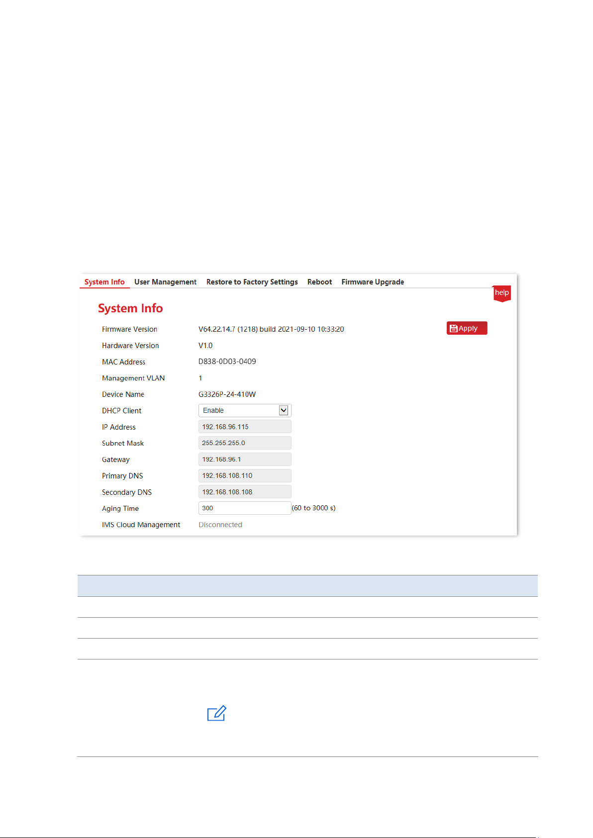
Click System Management > System Info to enter the page. On this page, you can view and
modify basic parameters of the switch.
Parameter description
Name
Description
Firmware Version
It displays the firmware version of the switch.
Hardware Version
It displays the hardware version of the switch.
MAC Address
It displays the MAC address of the switch.
Management VLAN
When VLAN mode is 802.1Q VLAN, the management VLAN of the switch is 1
and cannot be modified.
Note
The switch can be visited only when the computer is connected to the VLAN
port member (PVID of the port is 1).
Page 13

Version 1.0
Chapter 3 System management 7
Name
Description
Device Name
It displays the name of the switch.
DHCP Client
Enable/Disable DHCP client function
- Enable: The switch will automatically acquire IP address, subnet
mask, gateway and DNS server address from the DHCP server.
- Disable: Manual settings are required for IP address, subnet mask,
gateway and DNS server address to manage the device and connect
to Internet.
IP Address
The IP address of the switch. The default IP address is 10.16.16.168 and can
be modified when DHCP client is disabled.
Also, it is the management IP address of the switch which can be used to log
in to the web UI.
Subnet Mask
The subnet mask of the IP address. The default subnet mask is
255.255.255.0, and can be modified when DHCP client is disabled.
Gateway
The gateway address of the switch by default. It can be modified when
DHCP client is disabled.
Primary DNS
The primary/secondary DNS server address of the switch. It can be modified
when DHCP client is disabled.
Secondary DNS
Aging Time
The dynamic MAC aging time of the switch, which is 300s by default.
Tip
Short aging time will drive the dynamic MAC address table to refresh more
frequently and destination addresses in the received data packages cannot
be found. As a result, the switch is only capable of broadcasting these
packages to all ports, at the price of damaging the switch performance.
Long aging time will force the dynamic MAC address table to save up too
many stale addresses until it uses up all address tables. Eventually, the
switch fails to refresh them upon changing network.
IMS Cloud Management
It displays whether the switch is connected to the IP-COM IMS cloud
platform.
Page 14
Version 1.0
Chapter 3 System management 8
3.2 User management
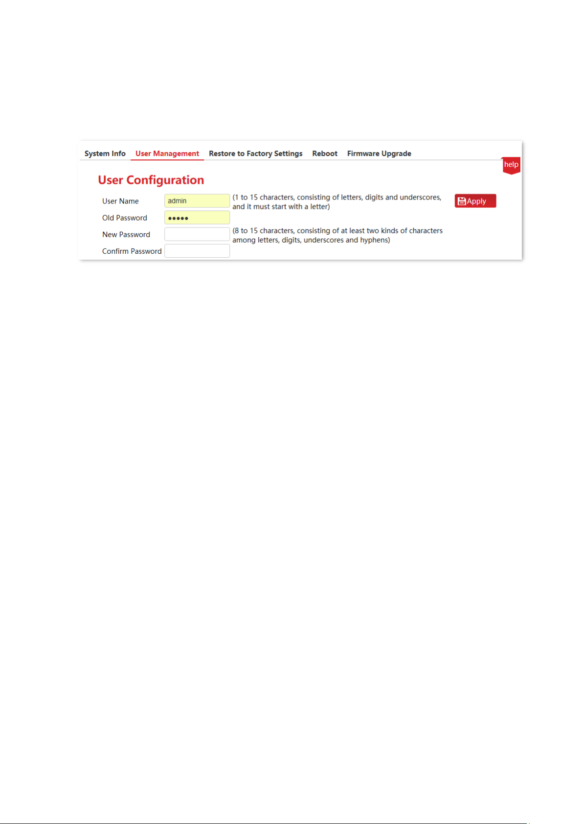
Click System Management > User Management to enter the page. Here, you can change the
login user name and password.
When you click Apply to save the change, the switch will reboot automatically and redirect to
the login page. Enter the new user name and password to log in to the web UI.
Page 15
Version 1.0
Chapter 3 System management 9
3.3 Restore to factory settings
If you cannot solve certain network issues, or you forget your user name or password when
logging in to the web UI of the switch, you can restore the switch to factory settings, and then
use the default user name and password (both are admin) to log in. This switch supports
Software reset and Hardware reset.
3.3.1 Software reset
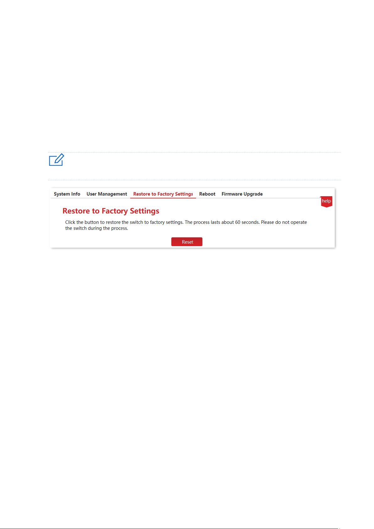
Click System Management > Restore to Factory Settings to enter the page.
Note
To avoid any damages, please ensure stable power supply to the switch during the resetting process.
3.3.2 Hardware reset
When the SYS LED indicator is blinking, press down the reset button (RESET) using a sharp item
(such as a pin) for about 7 seconds, and then release it when all indicators are solid on. When
the SYS LED indicator blinks again, the switch is restored to factory settings.
Page 16
Version 1.0
Chapter 3 System management 10
3.4 Reboot
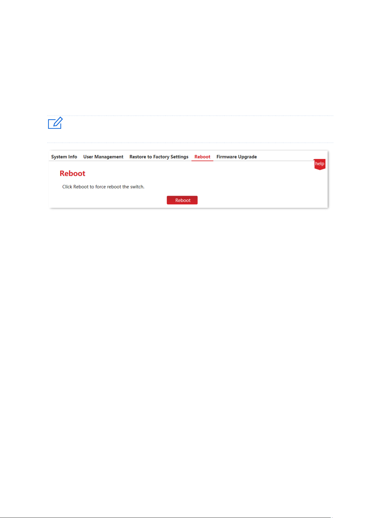
When a parameter you set does not work properly, you can try to reboot the switch to fix this
issue.
Click System Management > Reboot to enter the page. On this page, you can click Reboot to
restart the switch.
Note
Please click Save on the upper right corner to save all settings before rebooting the switch.
Page 17
Version 1.0
Chapter 3 System management 11
3.5 Firmware upgrade
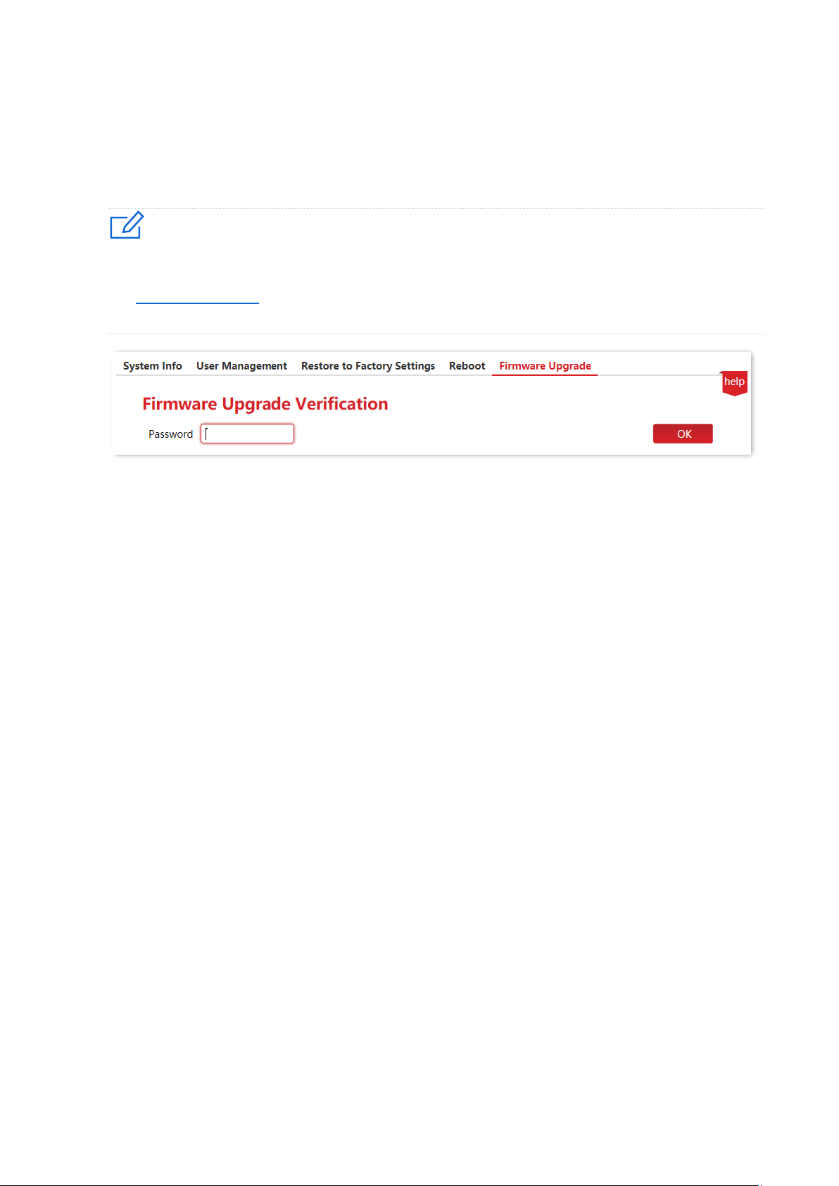
Click System Management > Firmware upgrade to enter the page. On this page, you can
upgrade firmware of the switch, getting better user experience.
Note
To avoid damages to the switch, ensure that the switch is upgraded properly. Please note that:
− Before upgrading, you can download the latest firmware of the switch on the IP-COM official website:
www.ip-com.com.cn. Generally, the filename extension of the upgrading file is .bin.
− During the upgrading process, ensure stable power supply to the switch.
The upgrade verification password is the login password of the web UI.
Page 18
Version 1.0
Chapter 4 Port management 12
4 Port management
4.1 Port configuration
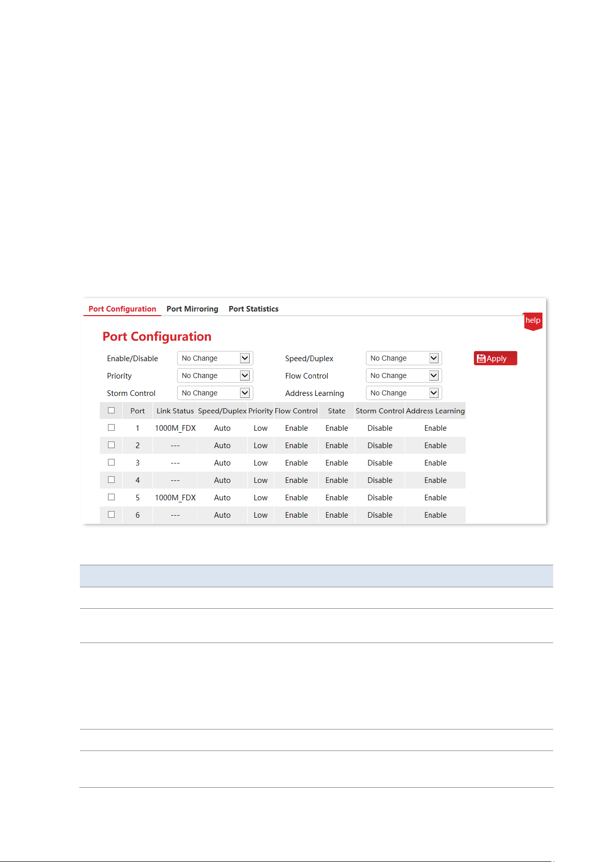
Click Port Management > Port Configuration to enter the page. On this page, you can view and
configure the basic parameters of the ports.
Parameter description
Name
Description
Port
It specifies the ID of the port.
Link Status
It specifies the current connection status and duplex mode of the port. “---”
indicates that the port is not connected or not negotiated successfully.
Speed/Duplex
It specifies the negotiation speed and duplex mode of the port.
−
Auto (Auto-negotiation): The port automatically negotiates the speed
and duplex mode with the peer device.
−
HDX: Half duplex mode.
−
FDX: Full duplex mode.
Priority
Select the port priority when setting QoS.
Flow Control
Enable/Disable the flow control function of the selected port. By default, the
port flow control is enabled.
Page 19

Version 1.0
Chapter 4 Port management 13
Name
Description
When the flow control of the switch and the terminal equipment are all
enabled, if some port congestion of the switch occurs, the port will send the
pause frame to the terminal equipment that will be suspended to send data
after receiving the pause frame. Meanwhile, when one port of the switch
receives a pause frame, the port also will be paused to send data.
Note
Enable the flow control to avoid the data packet loss caused by the
inconsistency of the sending and receiving rate. Yet that will also affect the
communication rate of the data source port and other facilities. Please be
careful with this function when linking the network port.
State
Enable/Disable the forwarding function of the selected port.
Storm Control
Enable/Disable the broadcasting storm control function of the selected port. By
default, the storm control is disabled.
Broadcast storm means that the broadcasting frame quantities are soaring up
due to the continuous transmissions, which brings negative effect on the
communication, degrades the system performance and even results in
breakdown of the network.
While enabling the storm control, the switch will discard the excessive
broadcasting messages as the broadcast traffic on the port exceeds the limited
value (2000pps), thus reducing the proportion of the broadcast traffic to the
limited range.
Address Learning
Enable/Disable the address learning function of the selected port.
While enabling the address learning, if no corresponding MAC address in the
MAC address table as the switch receives the data package, it will broadcast
this package to all ports. The switch will record the corresponding MAC port to
the MAC table when the destination host returns some information from one
port.
The MAC address table keeps the system port corresponding to the MAC
address of the host linking with that port.
Page 20
Version 1.0
Chapter 4 Port management 14
4.2 Port mirroring
Port mirroring is a method of copying and sending data from a port or multiple ports (source
ports) to a specified port (destination port) of the switch. The destination port is usually
connected to a data monitoring device, enabling you to monitor data traffic, analyze
performance and diagnose faults.
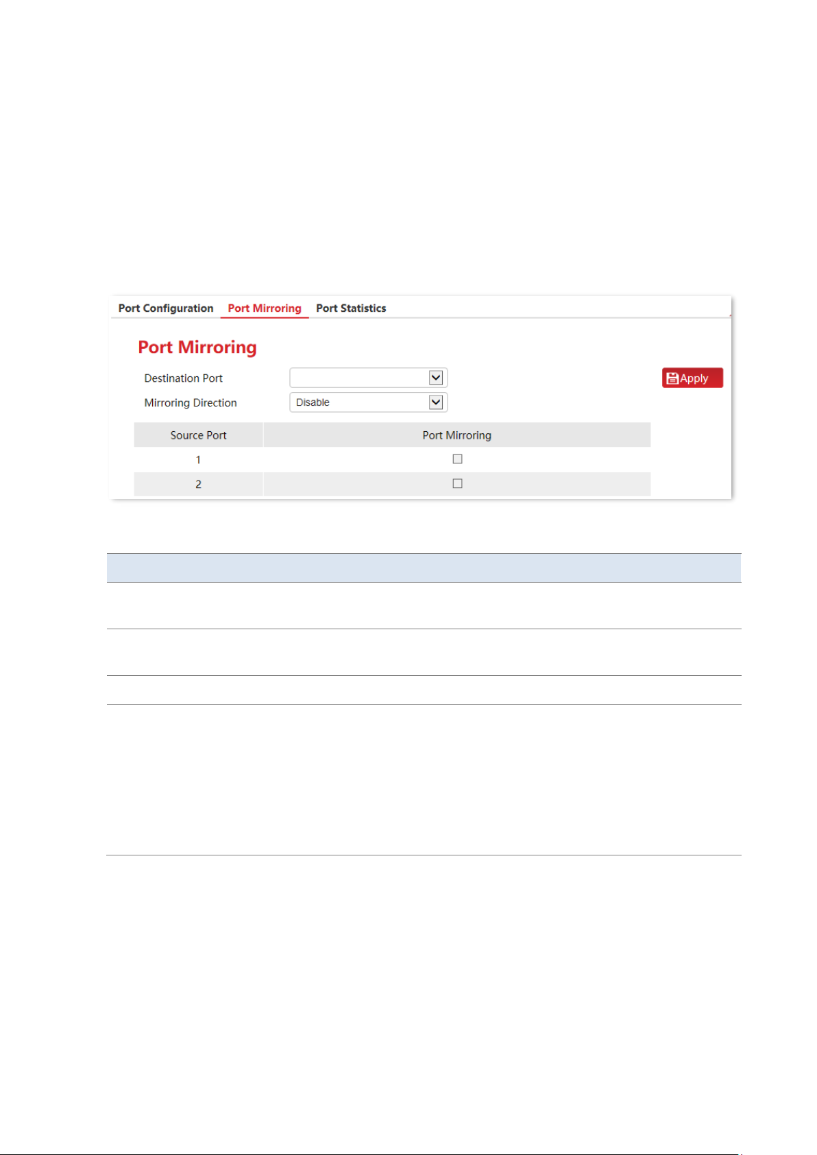
Click Port Management > Port Mirroring to enter the page. On this page, you can configure
the port mirroring rules.
Parameter description
Name
Description
Source Port
It specifies the ports whose packets will be copied. Multiple ports can be
selected.
Destination Port
Packets of source ports will be copied to this port. A mirroring group can
contain only one destination port.
Port Mirroring
Select the source port for port mirroring.
Mirroring Direction
It specifies the packet type.
−
Ingress: Packets received by source ports will be copied to the
destination port.
−
Egress: Packets transmitted by source ports will be copied to the
destination port.
−
Both (Two-way): Packets transmitted and received by source ports will
be copied to the destination port.
Page 21
Version 1.0
Chapter 4 Port management 15
4.3 Port statistics
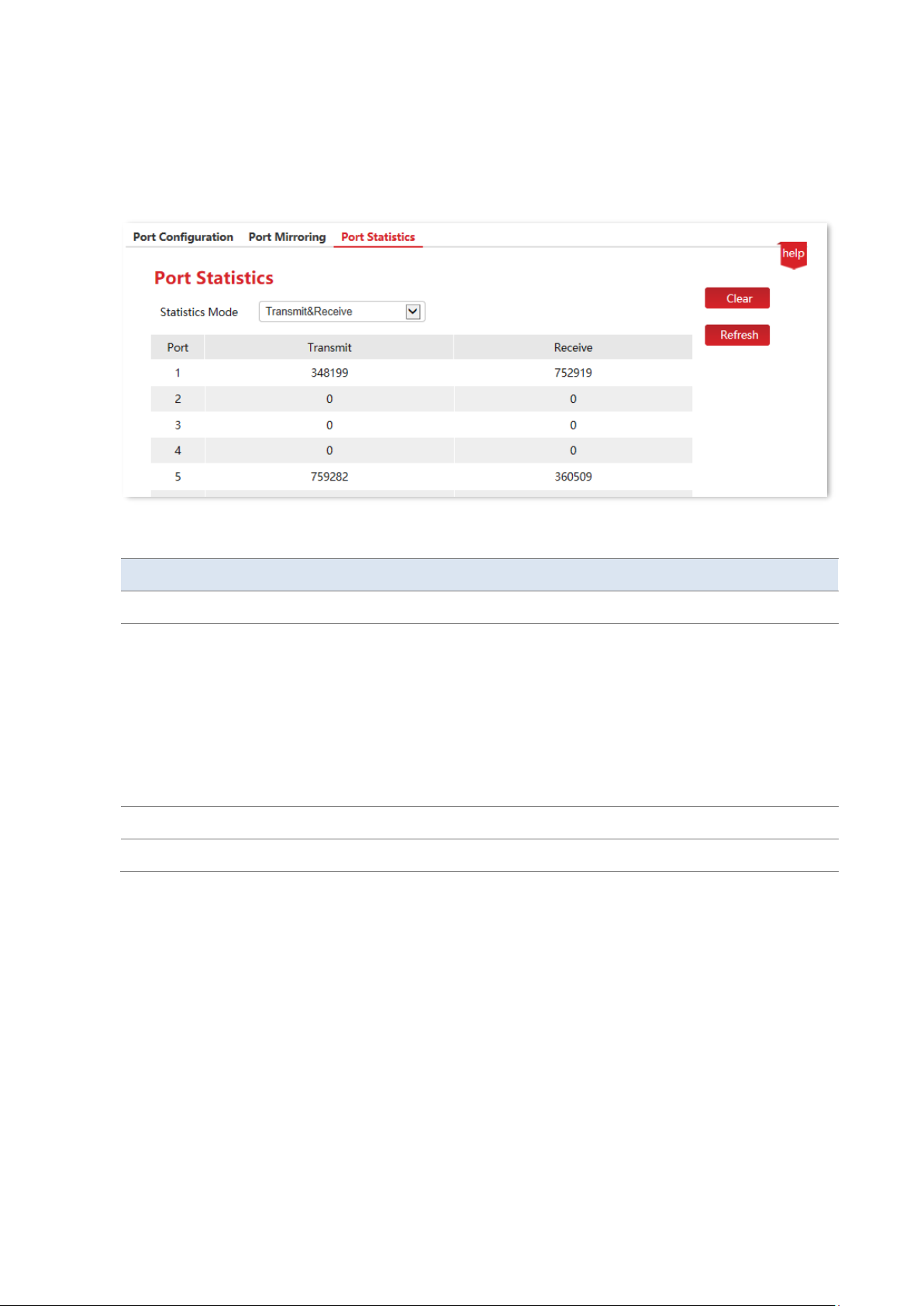
Click Port Management > Port Statistics to enter the page. On this page, you can view and
clear the packet statistics of each port.
Parameter description
Name
Description
Port
It specifies the ID of the port.
Statistics Mode
It specifies the statistics mode of port packets.
- Transmit & Receive: It specifies the number of transmitted and received
packets.
- Conflict & Transmit: It specifies the number of collision packets and the
number of transmitted packets.
- CRC Error & Receive: It specifies the number of CRC verification error
packets and received packets.
Clear
Clear port statistics of all ports.
Refresh
Refresh port statistics of all ports.
Page 22
Version 1.0
Chapter 5 Link aggregation 16
5 Link aggregation
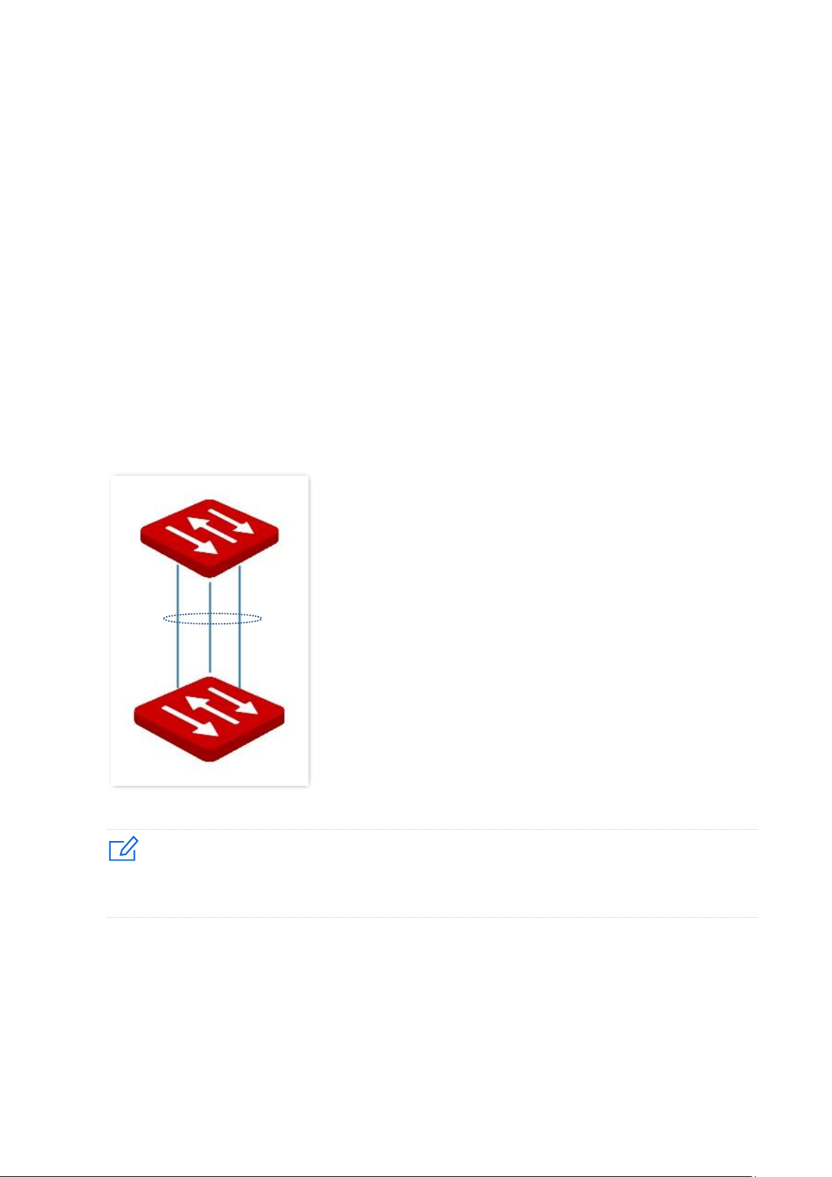
Link aggregation is used to converge multiple physical ports into a logical aggregation group.
Multiple physical links in one aggregation group are regarded as one logical link. The link
aggregation function binds multiple physical links into one logic link and enables them to share
traffic load for each other, thus increasing the bandwidth between the switch and the peer
device. Meanwhile, each member in an aggregation group backs up each other’s data
dynamically, improving connection reliability.
The network topology of link aggregation is as shown below.
In the same aggregation group, all member ports must be set to the same configurations with respect to STP,
QoS, VLAN configuration and port management.
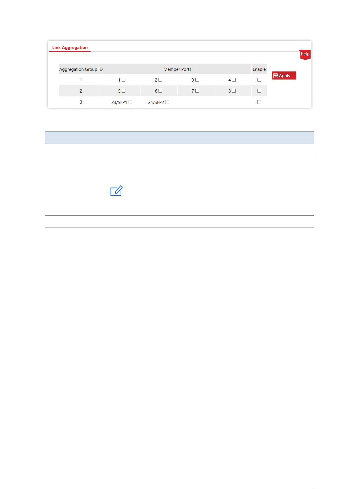
Click Link Aggregation to enter the page. On this page, you can configure the link aggregation
rules.
Note
This switch
Aggregation
group
Peer device
Page 23
Version 1.0
Chapter 5 Link aggregation 17
Parameter description
Name
Description
Aggregation Group ID
It specifies the ID of aggregation groups.
Member Ports
Select the members of an aggregation group.
The switch only supports static aggregation. In the static aggregation mode, all
member ports in the aggregation group converge into one logical port.
The aggregation mode of the switch needs to be the same as that of the peer
device. Otherwise, the data cannot be forwarded properly or the loops occur.
Enable
Enable the aggregation group.
Note
Page 24
Version 1.0
Chapter 6 Network extension 18
6 Network extension
Tip
This section only applies to the switches G3310P-8-150W, G3318P-16-250W and G3326P-24-410W.
The switch offers you the network extension function, which can extend the data transmission
and PoE Power Distance of downlink ports to make network deployment more convenient.
Once network extension is enabled, the port link speed will be automatically negotiated to
10Mbps. In this situation, if using the CAT5, CAT5E cable or better, the data transmission and
PoE power distance can break 100 meters and reach 250 meters.
It is recommended to enable the function when multiple IP cameras are connected to the
switch with long distance.
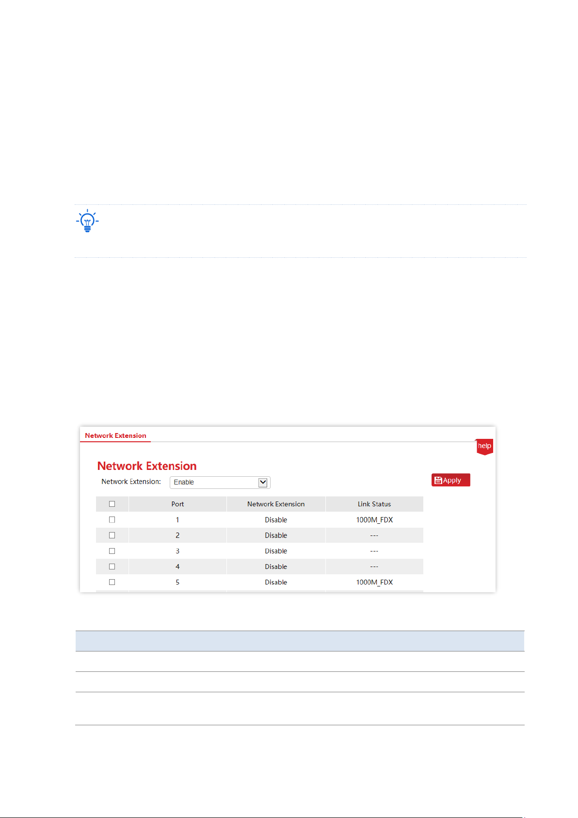
Click Network Extension to enter the page.
Parameter description
Name
Description
Network Extension
Enable/Disable network extension of the selected port.
Port
It displays the number of the port which can supply PoE power.
Link Status
It displays the speed and duplex mode of the port. If not connected or
negotiated failure, it will be shown as “---”.
Page 25
Version 1.0
Chapter 7 PoE management 19
7 PoE management
Tip
This section only applies to the switches G3310P-8-150W, G3318P-16-250W and G3326P-24-410W.
All downlink ports support PoE power supply and conform to IEEE 802.3af and IEEE 802.3at.
The switch will automatically supply required PoE power to the powered device which is
connected to the PoE port.
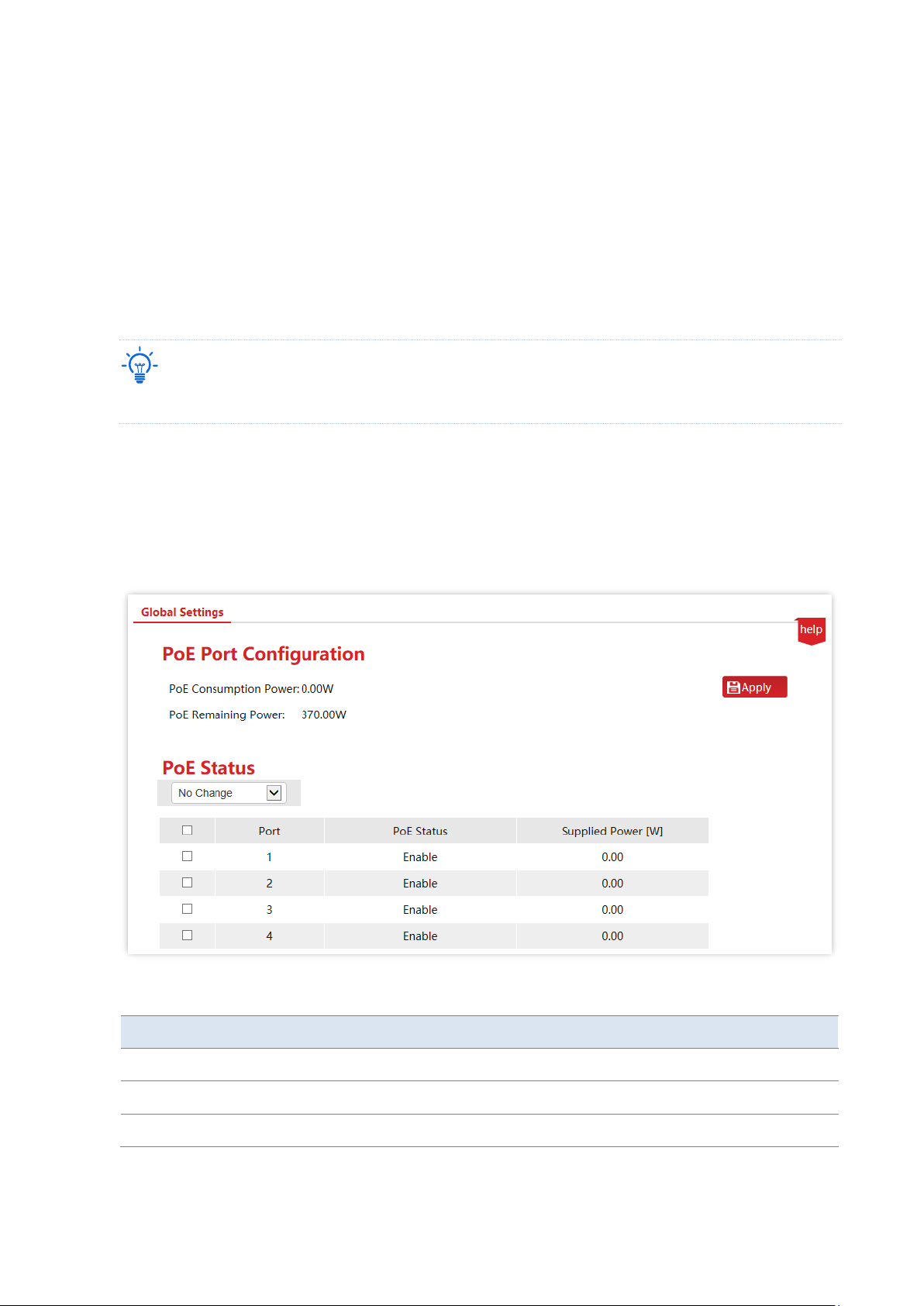
Click PoE Management to enter the page. You can check the PoE power status of the current
switch and enable/disable the PoE power function of the downlink port as well.
Parameter description
Name
Description
PoE Status
Enable/Disable the PoE power function of the selected port.
Port
It displays the downlink port number of the switch.
Supplied Power [W]
It displays the output power of the downlink port supplied by PoE.
Page 26

Version 1.0
Chapter 7 PoE management 20
Name
Description
PoE Consumption
Power
It displays the total output power of the switch supplied by PoE.
PoE Remaining Power
It displays the remaining output power of the switch supplied by PoE.
Page 27
Version 1.0
Chapter 8 VLAN management 21
8 VLAN management
8.1 Overview
VLAN (Virtual Local Area Network) is a technology that divides devices in LAN into different
logical, instead of physical, network segments to form virtual working groups. VLANs allow a
network station constituted by switches to be logically segmented into different domains for
broadcast isolation. All members in a VLAN are treated as in the same broadcast domain and
communicate as if they were on the same network segment, regardless of their physical
locations. Different VLANs cannot intercommunicate directly. Inter-VLAN communication can
only be achieved using a router or other layer-3 devices that are able to perform layer-3
forwarding.
The switch supports 802.1Q VLAN and can communicate with devices that support 802.1Q
VLAN in VLAN as well.
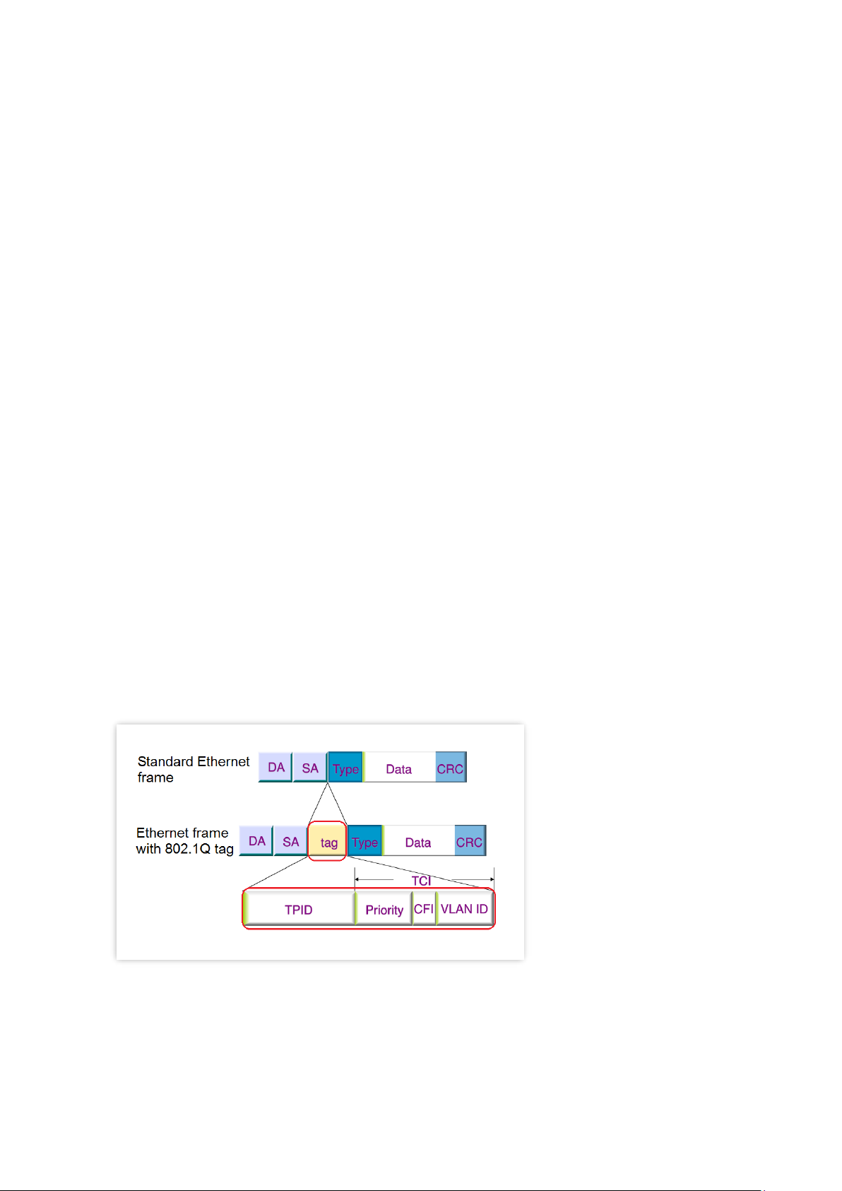
As defined by IEEE 802.1q protocol, one 4 bytes 802.1Q VLAN tab is bound to be wrapped
behind the destination MAC address and the source MAC address of the Ethernet frame for
identifying the relevant information of VLAN. As shown below, the Ethernet frame with 802.1Q
tag is produced by adding an 802.1Q VLAN tag behind the destination MAC address and the
source MAC address of the standard Ethernet frame.
Page 28
Version 1.0
Chapter 8 VLAN management 22
8.2 Configure 802.1Q VLAN
8.2.1 Create VLAN rules
A VLAN rule is created by default to ensure communication between switches in factory
settings. All ports are set to be members of this VLAN by default with the VLAN ID of 1 and the
IP address of 10.16.16.168. This rule cannot be deleted.
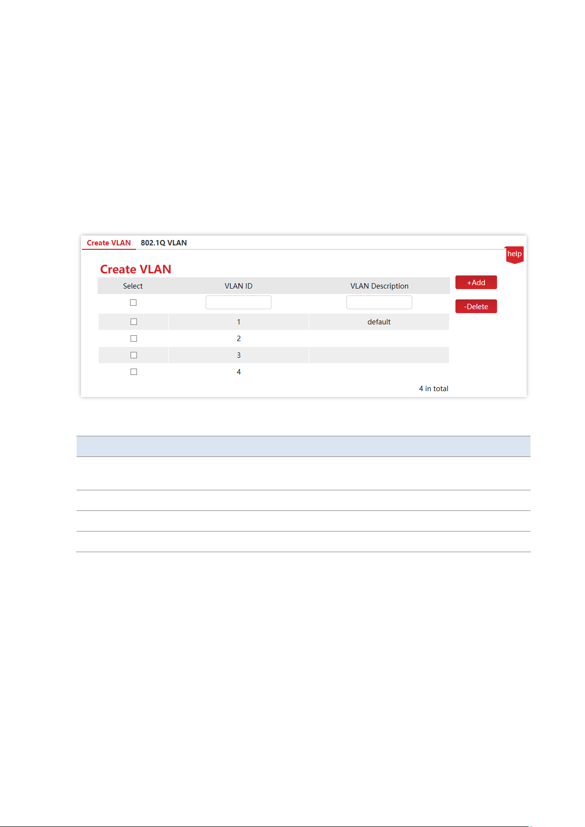
Click VLAN Management > Create VLAN to enter the page. On this page, you can configure the
rules of 802.1Q VLAN.
Parameter description
Name
Description
VLAN ID
It specifies the VLAN ID, used for identifying the VLAN to which the packet
belongs. The management VLAN ID is 1 and cannot be deleted.
VLAN Description
It is used to identify VLAN.
Add
It is used to add VLAN.
Delete
It is used to delete VLAN.
8.2.2 Configure VLAN port members
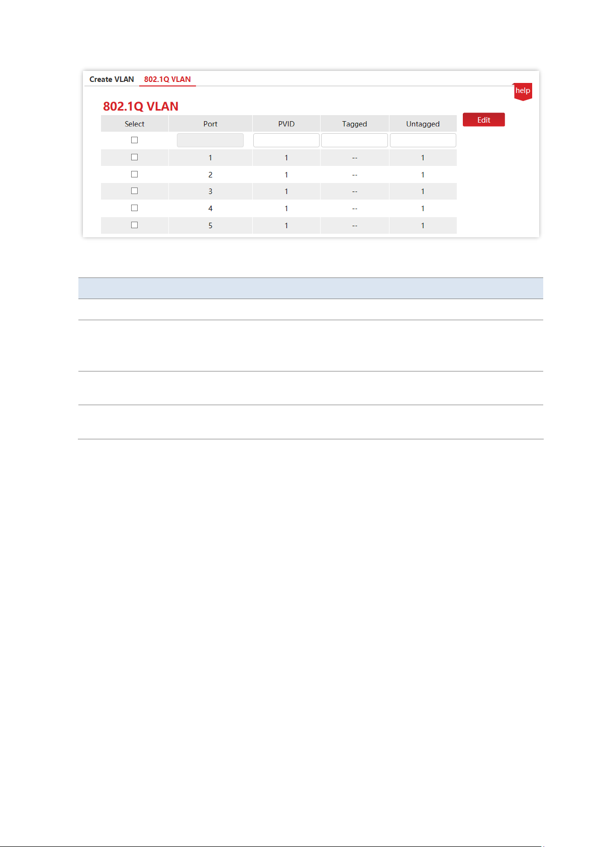
Click VLAN Management > 802.1Q VLAN to enter the page. On this page, you can configure
the PVID and Tag treatment policies of each port to realize VLAN isolation.
Page 29
Version 1.0
Chapter 8 VLAN management 23
Parameter description
Name
Description
Port
It specifies the ID of the port.
PVID
It specifies the VLAN ID of a port, which is 1 by default.
When receiving untagged packets, the port forwards them to the corresponding
VLAN based on the PVID of the port itself.
Tagged
If the VLAN ID of the tagged packets received by the port is the same with the
tagged VLAN, the port retains the tags of the packets and transmit them.
Untagged
If the VLAN ID of the tagged packets received by the port is the same with the
untagged VLAN, the port removes the tags of the packets and transmit them.
Page 30
Version 1.0
Chapter 8 VLAN management 24
8.3 Example of 802.1Q VLAN configuration
Networking requirement
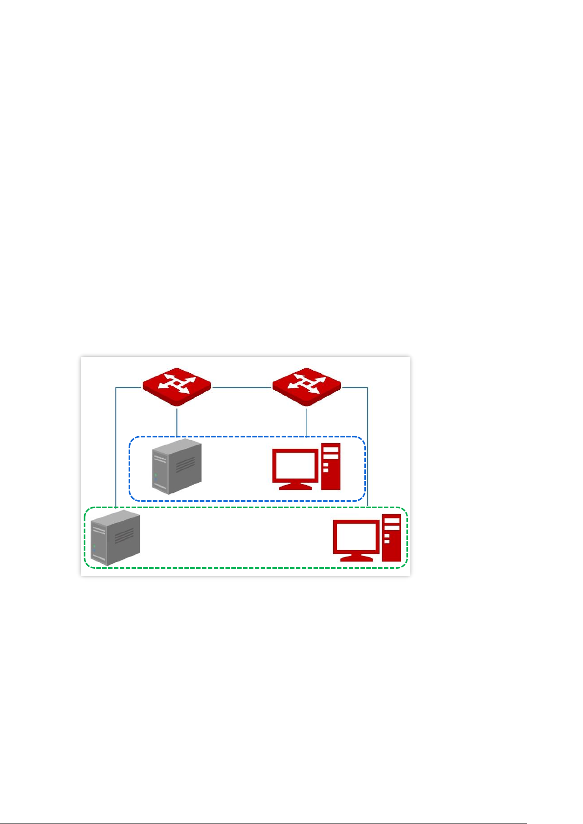
The staff in the financial department and marketing department of a company work on the
second floor, while the servers for these two departments are on the third floor. Now it is
required that the communication is available within each department and the servers can be
accessible respectively, but the two departments cannot communicate with each other.
Solution
Configure 802.1Q VLAN for two switches:
− Create two VLANs for the switches. Assign the ports connected to the financial
department’s devices to VLAN 5, and the ports to the marketing department’s
devices to VLAN 7.
− Add the ports that connect two switches to both VLAN 5 and VLAN 7.
Configuration procedure
Ⅰ. Configure Switch A
1. Create VLANs.
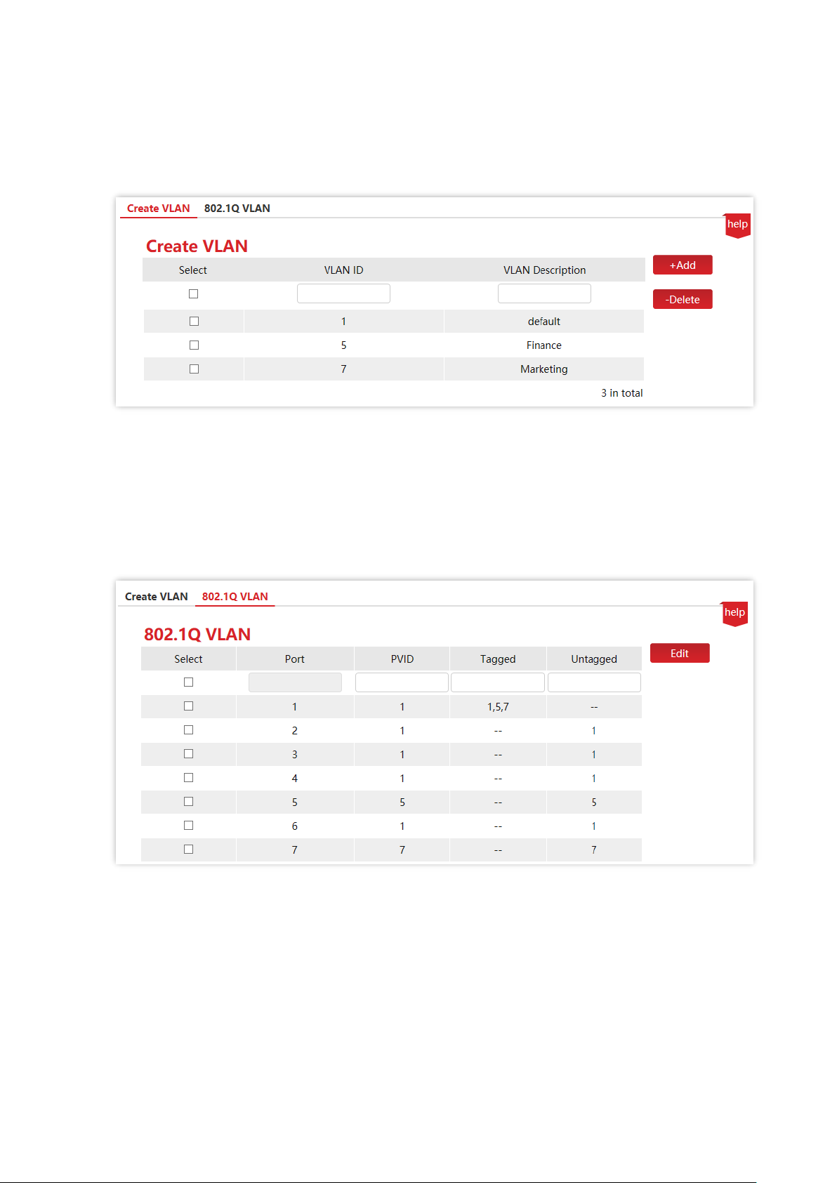
(1) Log in to the web UI of Switch A and click VLAN Management > Create VLAN.
(2) Enter the VLAN ID and VLAN Description and click +Add.
Port 1
Port 1
Port 5
Port 5
Port 7
Port 7
Financial
Department
VLAN 5
Marketing Department
VLAN 7
Switch A
Switch B
Page 31
Version 1.0
Chapter 8 VLAN management 25
- Set VLAN ID to 5.
- Set VLAN Description to Finance.
(3) Repeat step (2) and add another VLAN with the VLAN ID of 7 and VLAN Description of
Marketing.
2. Configure port attribute.
(1) Click VLAN Management > 802.1Q VLAN.
(2) Select port 5, set its PVID to 5, Untagged to 5, and click Edit.
(3) Select port 7, set its PVID to 7, Untagged to 7, and click Edit.
(4) Select port 1, set Tagged to 1,5,7, and click Edit.
Ⅱ. Configure Switch B
Refer to the steps of configuring Switch A.
----End
Page 32

Version 1.0
Chapter 8 VLAN management 26
Verification
The staff can access the server of their department, but cannot access the server of the other department.
The staff in the same department can communicate with each other but cannot communicate to the staff of
other departments.
Page 33
Version 1.0
Chapter 9 Device management 27
9 Device management
9.1 MAC binding
9.1.1 Overview
MAC binding provides the function of static MAC address table: After a port is bound with a
MAC address, the device that matches the designated MAC address can access the network
only through this port, not through other ports.
The MAC binding function ensures network security and user authority and effectively
prevents unauthorized users from gaining data by cheating and performing loiter net.
Tip
Bound MAC addresses are manually added and deleted, and will not be aged over time.
9.1.2 Configure MAC binding
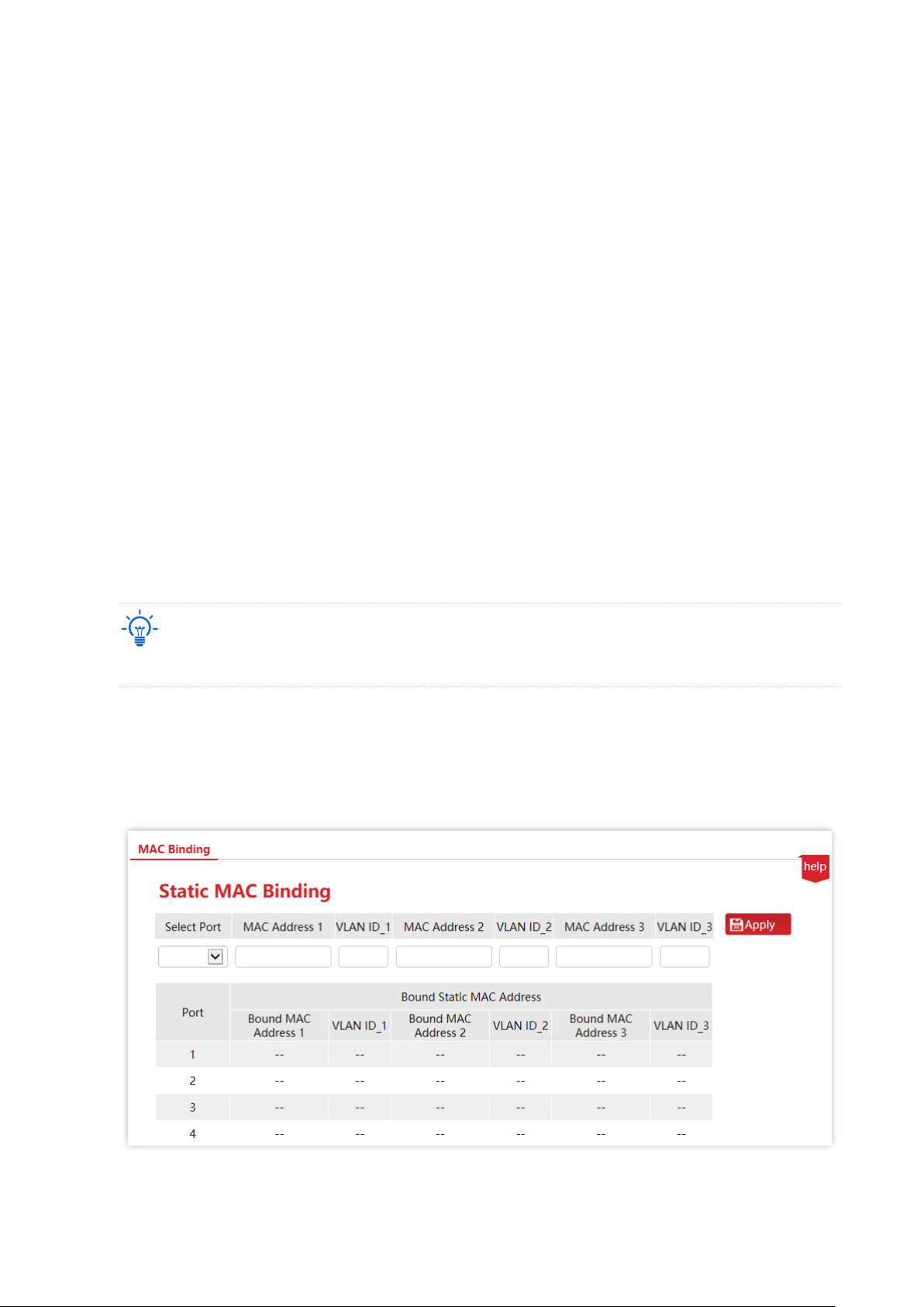
Click Device Management > MAC Binding to enter the page. On this page, you can perform
static MAC address binding.
Page 34
Version 1.0
Chapter 9 Device management 28
Parameter description
Name
Description
Select Port
Select a port whose static MAC address binding function needs to be configured.
MAC Address 1/2/3
Enter an access device MAC address bound to this port. The switch supports
binding up to three access devices.
Note
Broadcast or multicast address binding is not allowed.
VLAN ID_1/2/3
It specifies the VLAN to which the MAC address belongs.
Bound MAC
Address 1/2/3
It displays the bound MAC address.
9.1.3 Example of configuring MAC binding
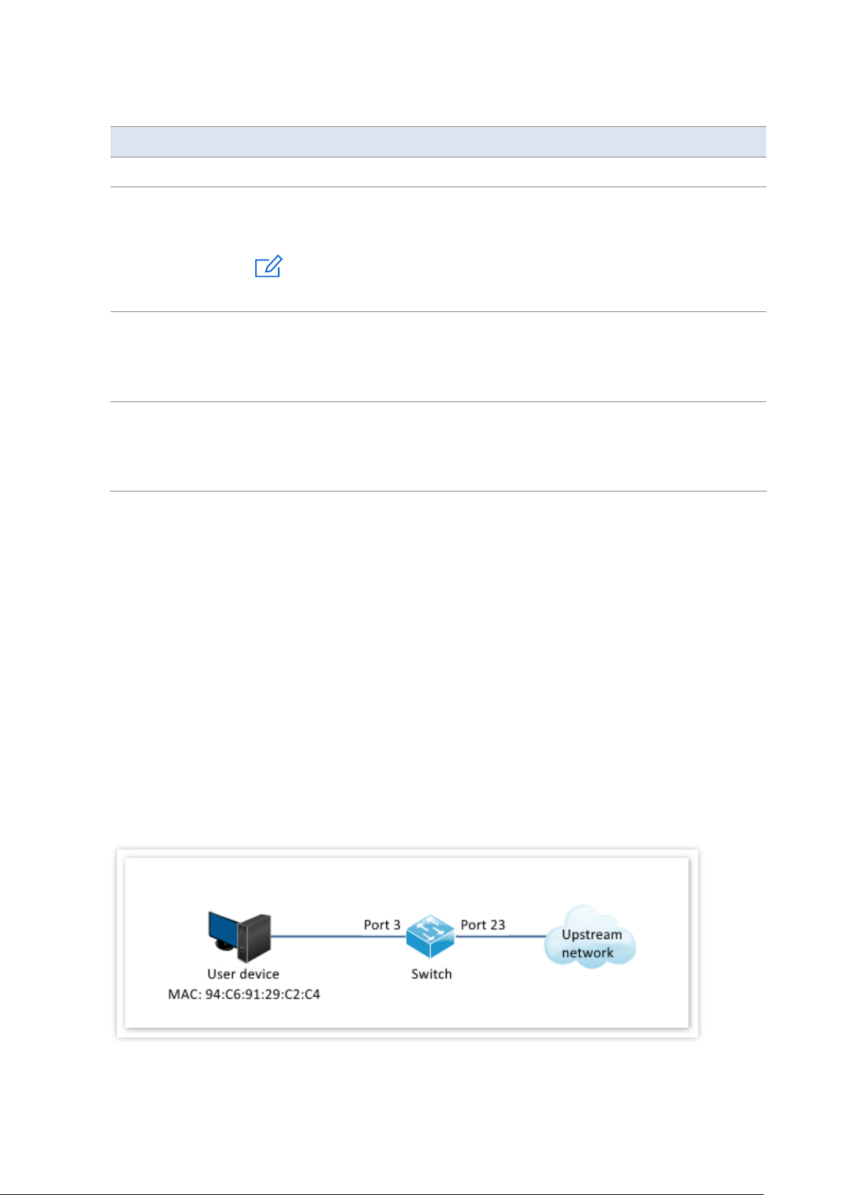
Networking requirement
The MAC address of the user device is 94:C6:91:29:C2:C4. Connect it to port 3 of the switch to
prevent other unauthorized users from performing loiter net or MAC addresses pretending to
be the authorized user from gaining data from other ports of the switch.
Solution
Bind the MAC address of the user device to port 3 of the switch.
Assume that the user device belongs to VLAN 1.
Page 35
Version 1.0
Chapter 9 Device management 29
Configuration procedure
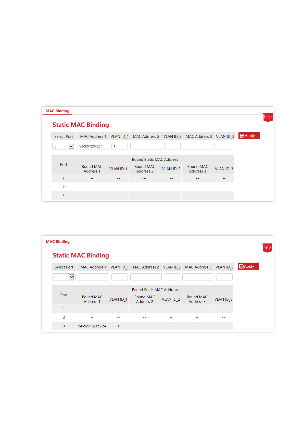
1. Log in to the web UI of the switch and click Device Management > MAC Binding.
2. Click the Select Port drop-down menu and select 3.
3. Enter the user device MAC address 94C69129C2C4 in the MAC Address 1 column, and set
VLAN ID_1 to 1.
4. Click Apply.
----End
MAC address is bound successfully. See the following figure.
Verification
The device with MAC address 94:C6:91:29:C2:C4 must be connected to port 3 of the switch to
access the higher-level network. If the device with MAC address 94:C6:91:29:C2:C4 is
connected to other ports of the switch, this device cannot access the higher-level network.
Page 36

Version 1.0
Chapter 9 Device management 30
9.2 QoS
Tip
This section only applies to the switches G3310P-8-150W, G3318P-16-250W and G3326P-24-410W.
9.2.1 Overview
In traditional IP network, packets are treated equally. This network service policy is known as
Best-Effort, which delivers the packets to their destinations with the best effort, with no
assurance and guarantee for delivery delay, reliability, and so on. Nowadays, in addition to
traditional applications such as www, FTP and E-mail, new services occur, such as video
conference, remote education, Video-on-Demand (VoD) and video telephone, which need
higher requirements for bandwidth, delay and jitter. QoS (Quality of Service) policy can meet
the above demands and improve the quality of service in the network.
This switch classifies the messages according to priority at the ingress stage, then maps them
to different queues at the egress stage, and finally forwards these messages by queues
according to the scheduling mode, so as to guarantee the quality of network service.
Scheduling mode
This switch provides the simple QoS function. By setting a port priority, the system first
discards packets on low-priority ports during network congestion to ensure transmission of
packets on high-priority ports. The switch has a total of two priority queues. Queue Low is of
low priority. Queue High is of high priority. The scheduling algorithms supported by the switch
are First in First out (FIFO), Strict Priority (SP), and Weighted Round Robin (WRR). By default,
the scheduling algorithm is FIFO.
Queue scheduling algorithms
◼ First in First out (FIFO)
FIFO is that packets that are received first are forwarded first. It applies to most network
applications such as email and FTP.
◼ Strict Priority (SP)
Strict priority scheduling algorithm is specially designed for critical service applications. An
important feature of critical services is that they demand preferential service in congestion in
order to reduce the response delay.
In queue scheduling, the messages are sent in queues strictly following the priority order from
high to low. When the queue with higher priority is empty, messages in the queue with lower
priority are sent. You can put critical service messages into the queues with higher priority and
put non-critical service messages (such as E-mail) into the queues with lower priority. In this
Page 37

Version 1.0
Chapter 9 Device management 31
way, critical service messages are sent preferentially, and non-critical service messages are sent
when the critical service messages are not sent.
Disadvantage of Strict Priority: If there are messages in the queues with higher priority for a
long time during congestion, the messages in the queues with lower priority will keep stuck
because they are not served.
◼ Weighted Round Robin Mode (WRR)
In this mode, packets in all the queues are sent in order based on the weight value for each
queue and every queue can be assured of a certain service time. Assuming there are 2 egress
queues on the port. The two weight values (namely, w2 and w1) indicate the proportion of
resources assigned to the two queues respectively. On a 100M port, if you set the weight
values of WRR queue-scheduling algorithm to 7 and 3 (correspond to w2 and w1 respectively).
Then the queue with the lowest priority can be ensured of, at least, 30 Mbps bandwidth, thus
WRR queue overcomes the disadvantage of SP queue that the packets in the queues with
lower priority cannot get service for a long time.
In WRR mode, though the queues are scheduled in order, the service time for each queue is
not fixed, that is to say, if a queue is empty, the next queue will be scheduled. In this way, the
bandwidth resources are made full use of.
Egress Discard
Messages are discarded on the egress port when congestion occurs in order to reduce the
loading of the ingress port.
This is applicable to following special scenarios: Both 100 Mbps ports and 1000 Mbps ports
exist when multicast packets are transmitted; perform RFC2889 test. This function is not
recommended in common scenarios.
9.2.2 Configure QoS
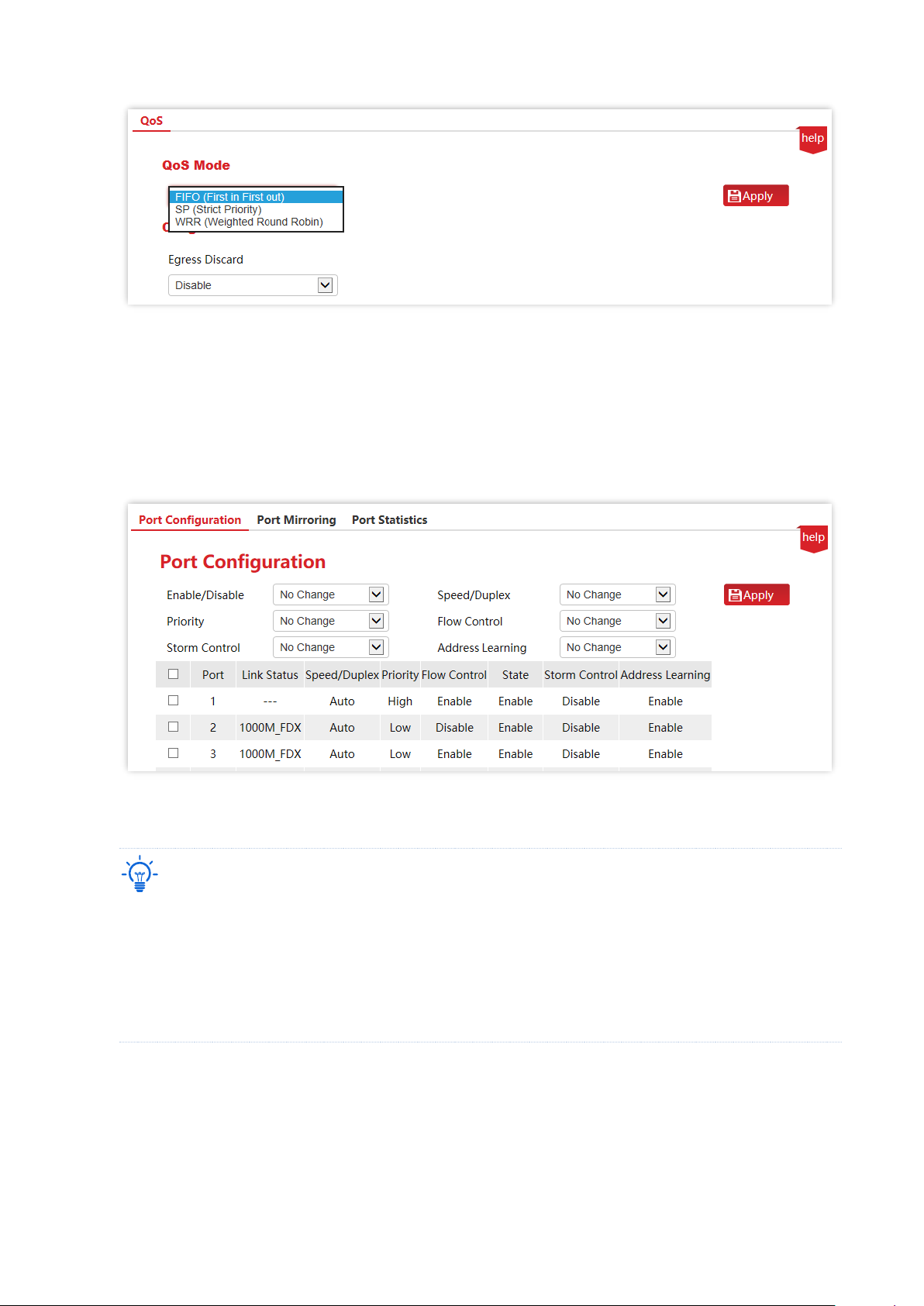
1. Configure QoS mode.
(1) Click Device Management > QoS.
(2) Select a priority mode from the QoS Mode drop-down menu. If WRR is selected, you must
also set Low weight and High weight. Note that the proportion of High must be greater
than that of Low. This series of switches support a proportion of 1-7.
Page 38
Version 1.0
Chapter 9 Device management 32
(3) Click Apply.
2. Set port priority.
(1) Click Port Management > Port Configuration.
(2) Select a port (port 1 and port 2 in this example) and set the Priority (High or Low).
(3) Click Apply.
----End
Tip
− Priority for all ports should be set to Low when FIFO mode is used.
− If the QoS mode is SP, set Port 1 to High and Port 2 to Low in Priority. When both ports send packets to
the same port at the same time, this port will let packets from Port 1 pass, followed by packets from
Port 2.
− If WRR is selected, set weights to High=7 and Low=1 respectively. When both ports send packets to the
same port at the same time, this port will send packets in a traffic proportion of 7:1.
Page 39

Version 1.0
Chapter 9 Device management 33
9.3 STP
9.3.1 Overview
Spanning Tree helps avoid loops in the network to protect the network from broadcast storms,
and provide link redundancy backup.
STP is a network protocol based on IEEE 802.1d. It is a protocol that ensures a loop-free
topology for local area network and provides backup redundant links. The devices under this
protocol discover the loops in the network by communicating with each other, and selectively
block some ports, and eventually establish a spanning tree structure without loops, so as to
prevent the decline of the message processing capacity of the devices due to the continuous
proliferation and endless circulation of messages in the loop network.
STP protocol message
To implement spanning tree function, switches in the network transfer BPDUs (Bridge Protocol
Data Unit) between each other to exchange information. BPDUs carry the information that is
needed for switches to calculate the spanning tree.
The network topology is determined by BPDU transmission among devices. There are two
types of BPDUs of STP protocol:
− Configuration BPDU: It is used for spanning tree calculation and spanning tree
topology maintenance.
− TCN BPDU (Topology Change Notification BPDU): It is used to notify the changes of
the network topology structure.
Basic concepts of STP
◼ Bridge ID
The bridge ID contains both bridge priority and MAC address, in which the bridge priority is a
configurable parameter. The smaller the bridge ID, the higher the bridge priority. The root
bridge is the bridge with the smallest bridge ID.
◼ Root bridge
Root bridge acts as the root of a tree. There is only one root bridge in the network and it is
changeable according to the network topology changes.
Initially, all devices regard themselves as the root bridges. They generate their own
configuration BPDUs and send them out periodically. When the network topology becomes
stable, only the root bridge device can send configuration BPDUs out and other devices can
only forward these BPDUs.
Page 40
Version 1.0
Chapter 9 Device management 34
◼ Root port
The root port is the port in a non-root bridge device that has the smallest path cost from the
bridge to the root bridge, responsible for communication with the root bridge. There is only
one root port on the non-root bridge device and no root port on the root bridge device.
◼ Designated bridge and designated port
− Designated bridge: For a switch, designated bridge is the device that connects to and
forwards BPDUs to the switch. For the LAN, it is the device that forwards BPDUs in
the same network segment.
In each network segment, the device with the least path cost to the root bridge is the
designated bridge. If more than one switch has the same path cost to the root bridge,
the one with the smallest bridge ID is the designated bridge.
− Designated port: As for a device, the designated port is the port that forwards BPDUs
to the host. As for a LAN, it is the port that forwards BPDUs in the same network
segment.
◼ Path cost
It is a parameter for choosing the link path by STP. By calculating the path cost, STP chooses the
better links and blocks the redundant links, so as to disbranch the loop-network to form a treetopological loop-free network.
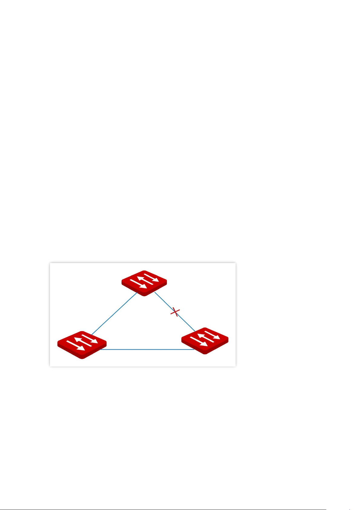
The basic network diagram of STP is shown as the following figure. The switch A, B and C are
connected successively.
After calculation, switch A is selected as the root bridge, and the link between ports A2 and C6
is blocked.
− Bridges: Switch A is the root bridge of the network, while switch B is the designated
bridge of switch C.
− Ports: Port B3 and port C5 are the root ports of switch B and switch C respectively.
Port A1 and port B4 are the designated ports of switch A and switch B respectively.
Port C6 is the blocking port of switch C.
Switch B
Switch C
Port A1
Port A2
Port B3
Port B4
Port C5
Port C6
Switch A
Page 41

Version 1.0
Chapter 9 Device management 35
BPDU priority in STP mode
The smaller the bridge ID is, the higher the bridge priority is. If the root bridge ID is the same,
then the root path costs are compared. The comparison method is to assume the root path
cost in BPDU and the path cost corresponding to this port to be S, then the BPDU with smaller
S has higher priority.
If the root path costs are the same, compare the designated bridge ID, designated port ID and
ID of the port that receives the BPDU successively, one with the smallest ID has higher priority.
STP computing process
1. Initial status
Initially, each port of the switch generates a BPDU regarding the switch as the root bridge, with
the root path cost being 0, the ID of the designated bridge being the switch ID, and the
designated port being itself.
2. Optimal BPDU selection
Each switch sends out its BPDUs and receives BPDUs from other switches. The following table
shows the procedure to select the optimal BPDU.
Step
Content
1
Receiving BPDU with lower priority: If the priority of the BPDU received by a port is lower than
that of the port itself, the switch discards the received BPDU and does not deal with the BPDU of
that port.
Receiving BPDU with higher priority: If the priority of the received BPDU is higher than that of
the port itself, the switch replaces the BPDU of the port with the received one.
2
The switch selects the best BPDU by comparing BPDUs on all ports.
3. Root bridge selection
The root bridge is selected by BPDU exchange and root bridge ID comparison. The switch with
the smallest root bridge ID is chosen as the root bridge.
4. Root port and designated port selection
The selection procedure is shown in the following table.
Step
Content
1
For each switch (except the root bridge), the port that receives the optimal BPDU is chosen as
the root port of the switch.
2
The switch calculates a designated port BPDU for each port according to the root port BPDU and
root port path cost.
−
The ID of the root bridge is replaced with that of the root port.
Page 42

Version 1.0
Chapter 9 Device management 36
Step
Content
−
Root path cost is replaced with the sum of the root path cost of the root port BPDU and
the path cost corresponding the root port.
−
The ID of the designated bridge is replaced with that of the switch itself.
−
The ID of the designated port is replaced with the port ID itself.
3
The switch compares the calculated BPDU with the BPDU of the port whose role requires to be
determined, and deals with the port according to different comparison results.
−
If the calculated BPDU takes the precedence over the BPDU of the port, the port is chosen
as the designated port with its BPDU replaced with the calculated BPDU, and regularly
sends out the BPDU.
−
If the BPDU of this port takes the precedence over the calculated BPDU, the BPDU of this
port is not changed and the port is blocked. The port only receives BPDUs but cannot
forward BPDU or other data.
Tip
In a stable topology, only the root ports and designated ports can forward data, and other ports are blocked.
The blocked ports can only receive BPDUs, but not forward data.
STP Timer
◼ Hello Time
It specifies the interval for the root bridge to send BPDU messages to other switches, used to
test if the links malfunction.
◼ Maximum Aging Time
It specifies the maximum duration during which if a switch does not receive a BPDU message
from the root bridge, it sends BPDU packets to all the other switches for recalculating the new
STP.
◼ Forwarding Delay
It specifies the delay time the port state migration takes after the network topology changes.
Link malfunction leads to STP recalculation in the network, in which case, the STP structure will
change accordingly. However, as the new BPDUs cannot be spread to the whole network
immediately, the temporal loops might occur if the new root ports and the designated ports
forward data at once. Therefore, STP adopts a state migration mechanism, that is, the new root
ports and designated ports begin to forward data after twice forwarding delay, which ensures
the new BPDUs have been spread to the whole network.
Page 43
Version 1.0
Chapter 9 Device management 37
RSTP
RSTP is defined by the IEEE 802.1w standard and downward compatible with IEEE 802.1d STP.
In addition to a loop-free network and redundant links, it features with fast convergence. If all
bridges in a LAN support RSTP, it enables a rapid topology tree generation when the network
topology changes (traditional STP topology tree: 50 seconds, RSTP topology tree: 1 second).
RSTP determines the network topology by exchanging BPDUs among switches. However, the
BPDU format of RSTP differs from that of STP. When the topology is changing, RST-BPDU
messages are spread by floods to notify the change to the whole network.
Conditions for rapid state migration of the root ports and designated ports in RSTP:
− Root port: The original root port of the switch stops forwarding data and the
designated port of the upstream switch begins to forward data.
− Designated port: If the designated port is an edge port, it can directly transit to
forwarding state; if the designated port is a P2P port, it can transit to forwarding
state once it gets response from the downstream switch through handshake.
◼ Edge Port
An edge port is a designated port on the edge of the switching network. It is directly connected
to terminal devices. An edge port can transit to forwarding state immediately without going
through listening and learning states. If it receives a BPDU, it immediately turns from an edge
port to a common spanning tree port, and joins the STP generation.
◼ P2P Port
A P2P port used to connect to other switches. Under RSTP/MSTP, all ports operating in fullduplex mode are P2P ports.
9.3.2 STP global settings
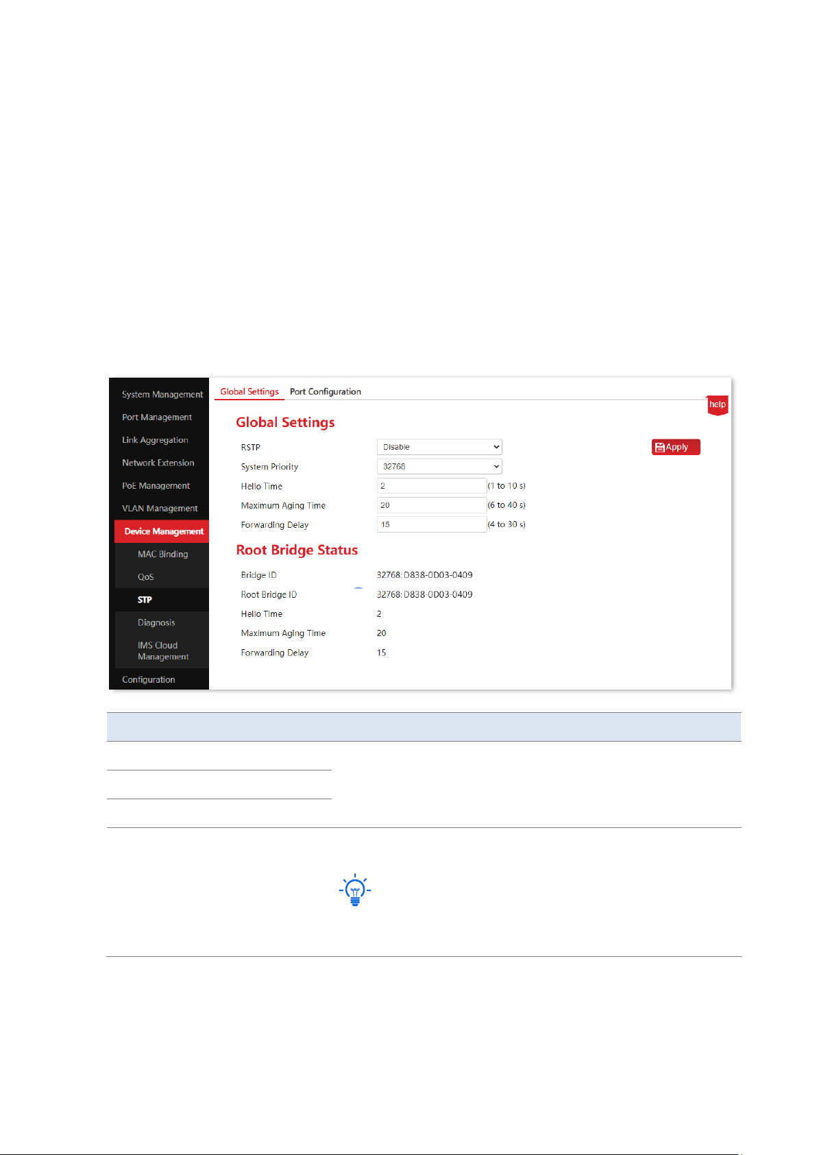
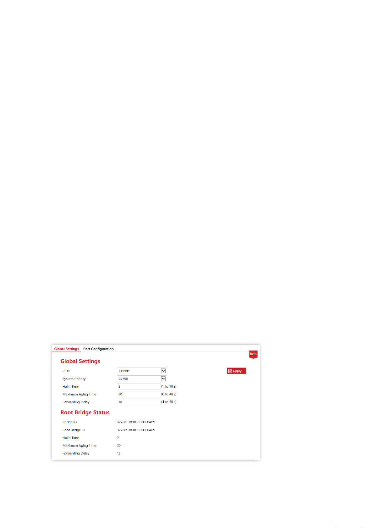
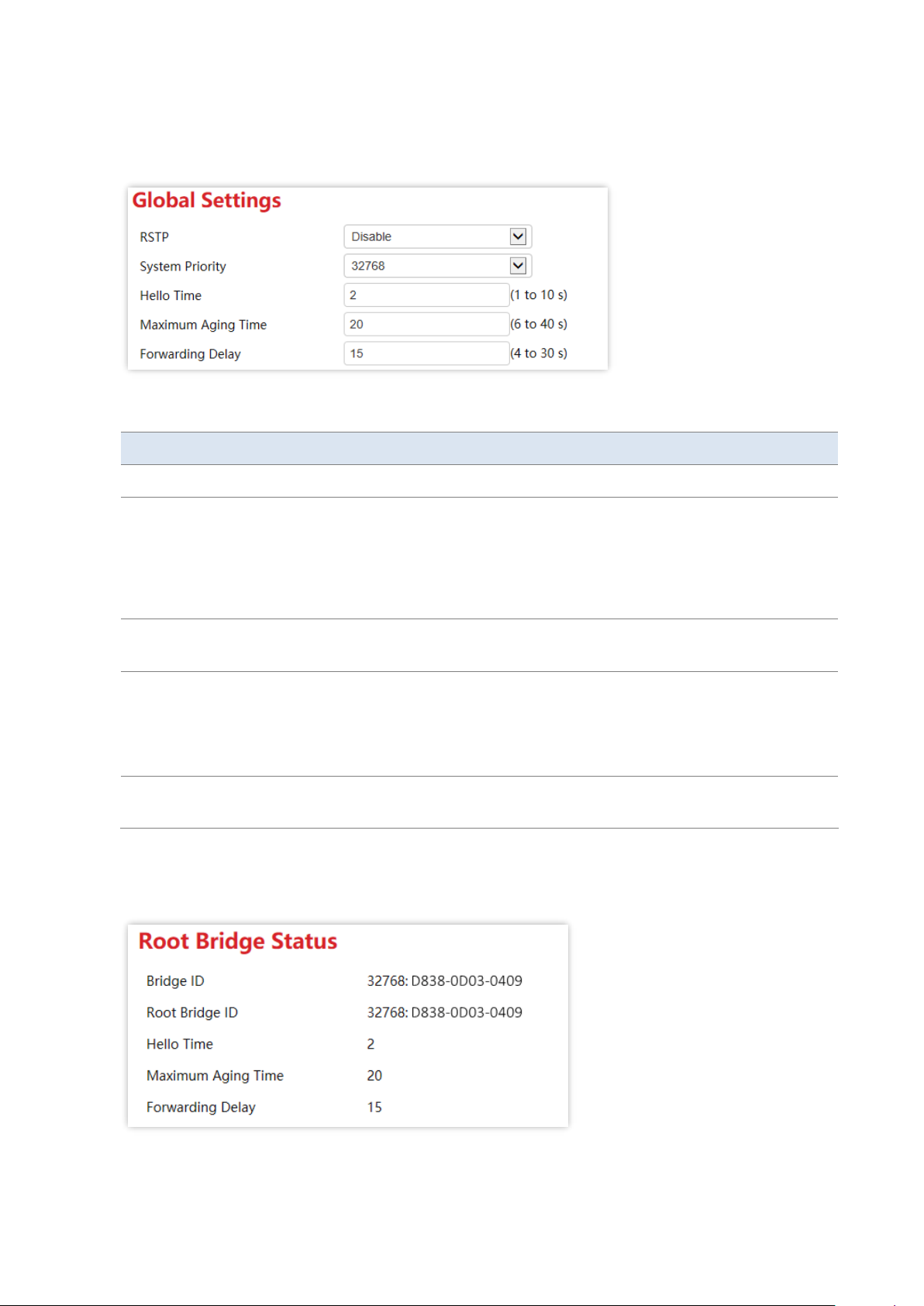
Click Device Management > STP > Global Settings to enter the page.
Page 44
Version 1.0
Chapter 9 Device management 38
Global settings
It is used to configure and view the global properties of spanning tree functions of the switch.
Parameter description
Name
Description
RSTP
Enable/Disable RSTP function of the switch.
System Priority
Set the priority of the switch.
Priority is an important reference to determine whether the switch will be selected
to work as root bridge, and switch with higher priority will be selected to work as
root bridge under equivalent conditions. The lower the value, the higher the
priority. Priority is 32768 by default.
Hello Time
It specifies the interval at which the switch sends BPDU, which is set to 2 seconds
by default.
Maximum Aging
Time
It specifies the maximum duration during which the BPDU can be kept in the
switch. The configuration should meet the following formulas:
−
Maximum Aging Time ≥ 2 × (Hello Time + 1)
−
Maximum Aging Time ≤ 2 × (Forwarding Delay - 1)
Forwarding Delay
It specifies the delay that the port state migration takes after the network topology
changes, which is set to 15 seconds by default.
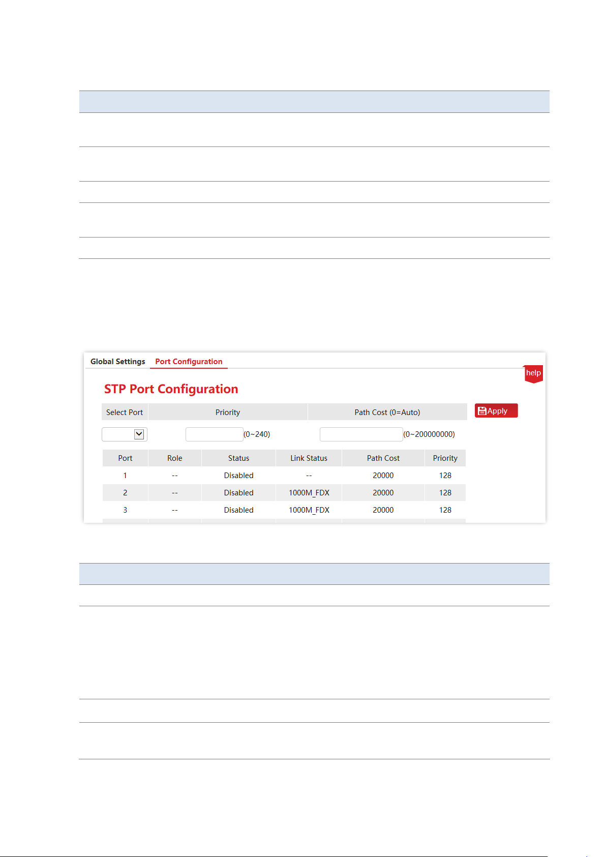
Root bridge status
Page 45
Version 1.0
Chapter 9 Device management 39
Parameter description
Name
Description
Bridge ID
It displays the bridge ID of current switch which is comprised of the system priority
and MAC address of the switch.
Root Bridge ID
In the entire network spanning tree, it is selected to serve as a bridge ID of root
bridge device.
Hello Time
It displays the Hello Time value of Root bridge setting.
Maximum Aging
Time
It displays the value of maximum aging time of root bridge setting.
Forwarding Delay
It displays the value of forwarding delay of root bridge setting.
9.3.3 STP port configuration
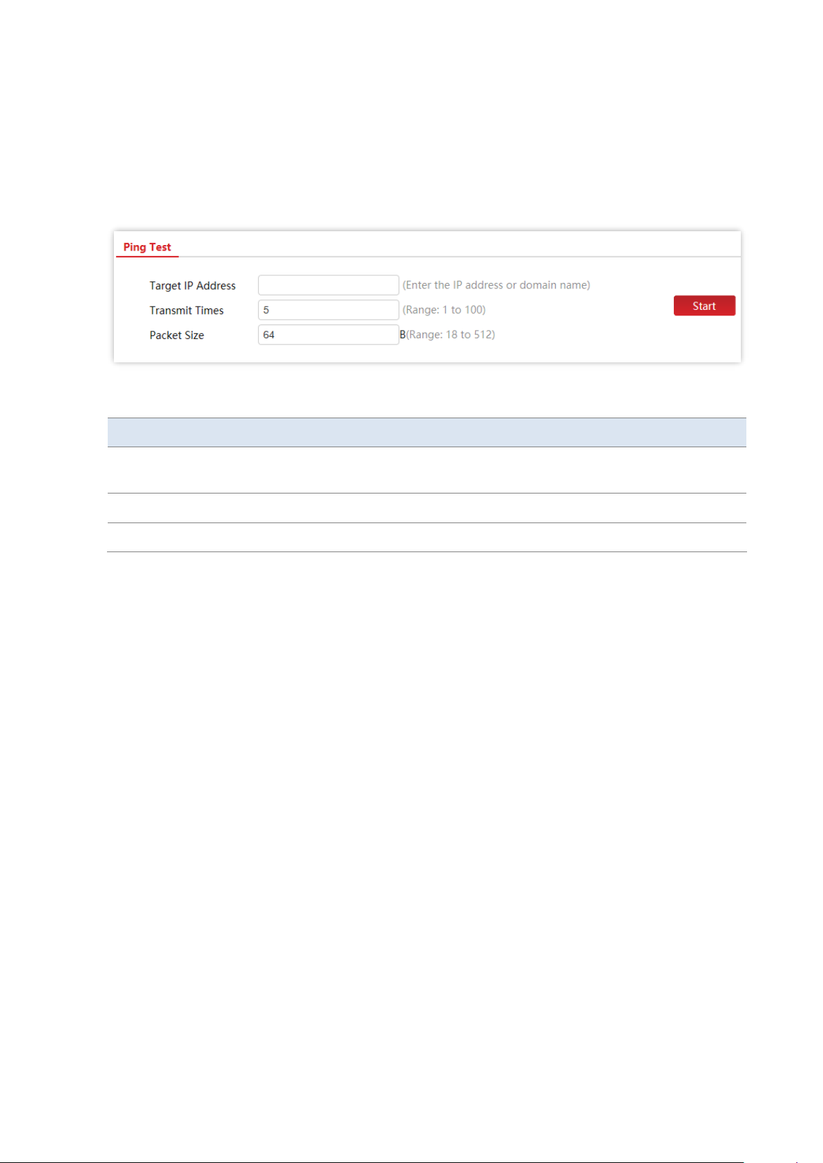
Click Device Management > STP > Port Configuration to enter the page. On this page, you can
configure the STP parameters of the ports.
Parameter description
Name
Description
Select Port
Select the port to be set.
Priority
Set the port priority, effective values are integral multiples of 16, and the lower the
value, the higher the priority.
Port priority is an important reference to determine whether the ports connected
to port will be selected to work as root ports. Ports on downstream device
connected to a port with a higher priority will be selected to work as root port
under equivalent conditions.
Path Cost (0=AUTO)
Set the path cost of port.
Role
It displays the role of port: Root, Designated, Alternate, Backup and --.
“--” indicates that the port is not connected or that the STP function of switch is
Page 46

Version 1.0
Chapter 9 Device management 40
Name
Description
disabled.
Status
It displays the status of the port: Forwarding, Learning, Listening, Blocking, Discard
and Disabled.
Link Status
It displays the rate and duplexing mode of the port. “--” indicates that the port is
not connected or negotiation fails.
Page 47
Version 1.0
Chapter 9 Device management 41
9.4 Diagnosis
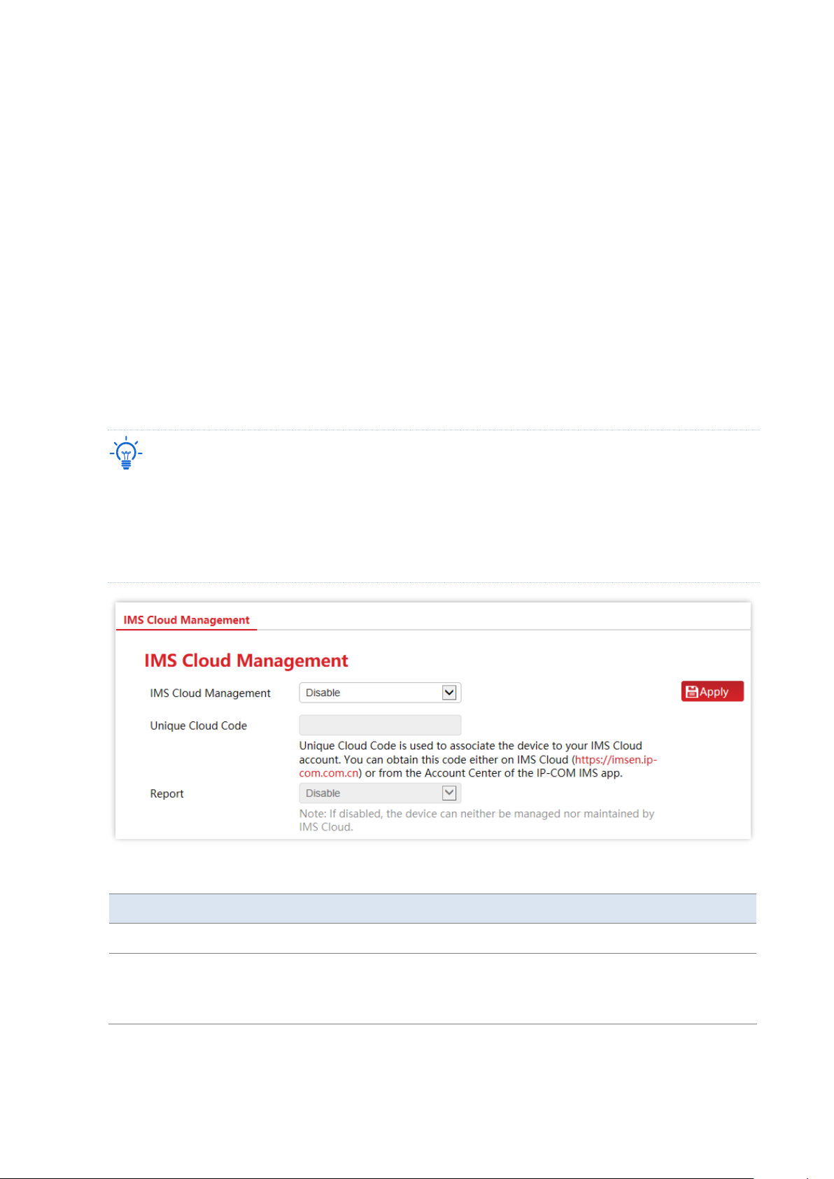
Click Device Management > Diagnosis to enter the page. On this page, you can perform Ping
test to test network connection and connection quality.
Parameter description
Name
Description
Target IP Address
It specifies the IP address or domain name of the destination device to
be pinged.
Transmit Times
It specifies the number of data packets sent by Ping.
Packet Size
It specifies the size of data packets sent by Ping.
Page 48
Version 1.0
Chapter 9 Device management 42
9.5 IMS cloud management
9.5.1 Overview
IP-COM IMS Business Cloud Platform is a cloud platform established by IP-COM, providing
central management for IP-COM devices that support IMS cloud management.
With this switch managed by the IMS cloud platform, you can configure and check the
parameters of the switch on the IMS cloud platform. You can also configure and check these
parameters on the web UI of the switch.
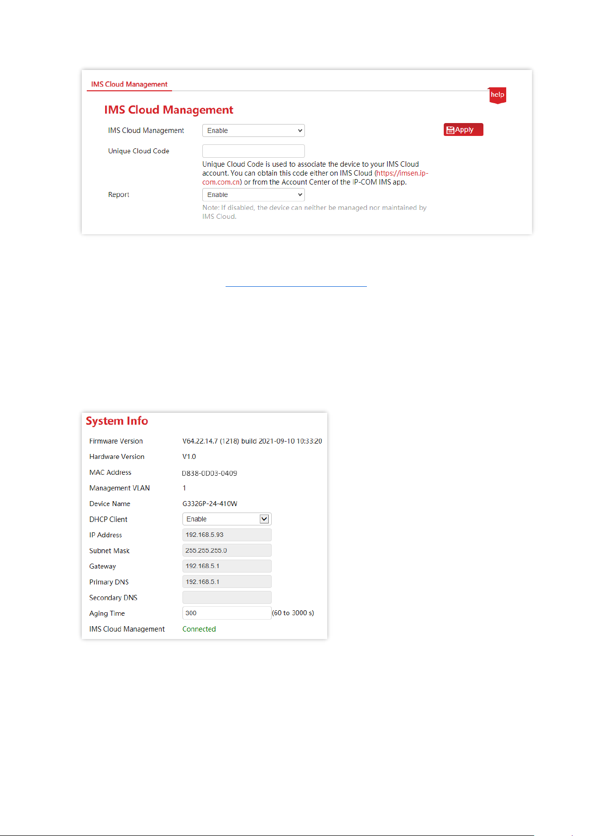
To enable IMS Cloud Management function of the switch, click Device Management > IMS
Cloud Management to enter the page.
Tip
− Please ensure that the switch can access the internet, otherwise it cannot be managed by the IMS cloud
platform.
− With the switch managed by the IMS cloud platform, you can modify the parameters of the switch on
both the IMS cloud platform or web UI of the switch. The parameters of the switch take effect based on
the last modification.
Parameter description
Name
Description
IMS Cloud Management
It is used to enable or disable the IMS Cloud Management function.
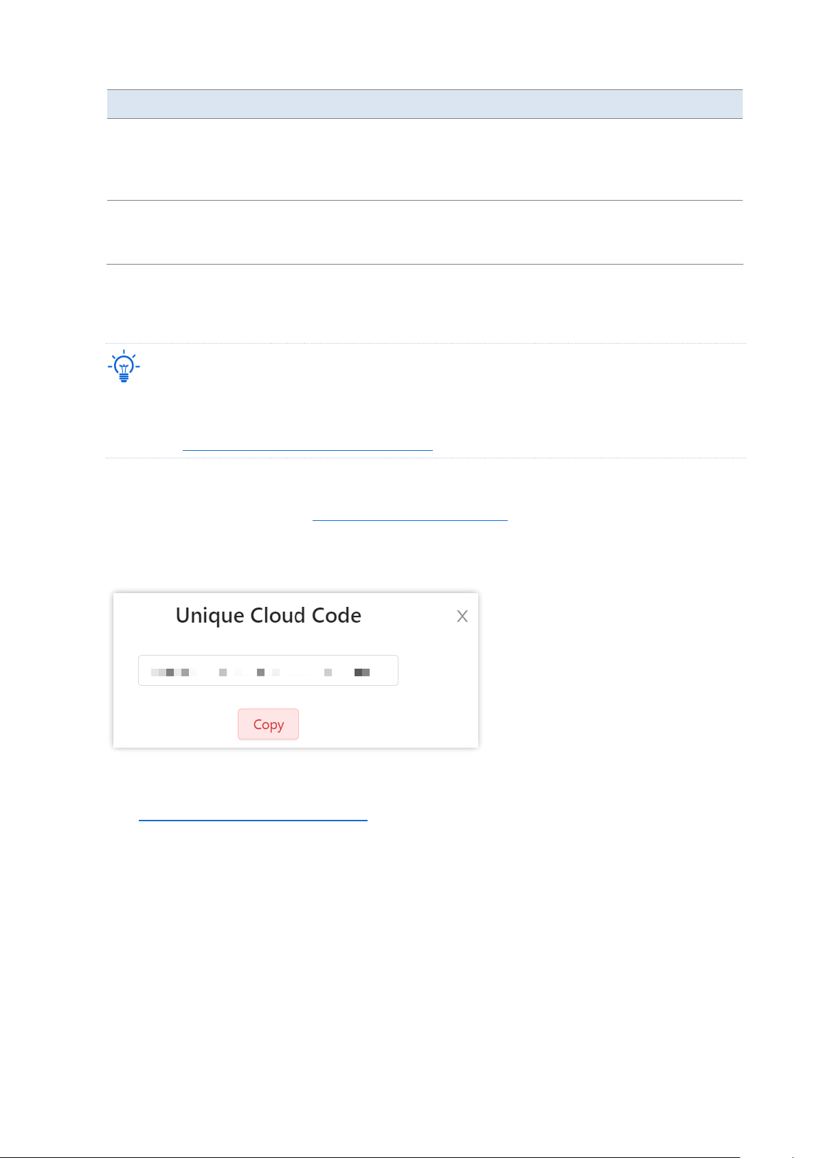
Unique Cloud Code
It is used to associate the device with your IP-COM IMS Business Cloud
Platform account.
Methods to obtain this code:
Page 49
Version 1.0
Chapter 9 Device management 43
Name
Description
−
IMS cloud platform: Log in to the IP-COM IMS Business Cloud
Platform, click your account name on the upper right corner, and
you can find Unique Cloud Code on the drop-down list.
−
IMS app: Find it in the Account Center of the IP-COM IMS app.
Report
Only with this function enabled, the switch can be managed by the IMS
cloud platform, and its configuration can be reported to the IMS cloud
platform.
9.5.2 Management on IP-COM IMS Cloud
Tip
− Before configuring the IMS Cloud Management function, please ensure that the switch has connected to
the internet.
− Refer to Configure the switch to access the internet if necessary.
1. Log in to IP-COM IMS Cloud and obtain Unique Cloud Code.
(1) Start a web browser, visit https://imsen.ip-com.com.cn, and log in to IP-COM IMS Cloud.
(2) Click the personal avatar at the upper right corner and select Unique Cloud Code.
(3) Click Copy to copy the Unique Cloud Code.
2. Enable the IMS Cloud Management function of the switch.
(1) Log in to the web UI of the switch.
(2) Click Device Management > IMS Cloud Management.
(3) Enable the IMS Cloud Management function, paste the copied Unique Cloud Code,
enable the Report function, and click Apply.
Page 50
Version 1.0
Chapter 9 Device management 44
3. Log in to the IMS cloud platform and add the switch to a project.
(1)
Start a web browser, visit https://imsen.ip-com.com.cn, and log in to IP-COM IMS Cloud.
(2)
Click the personal avatar at the upper right corner and select Device-Joining Alert.
(3) Locate this switch and add it to your project.
----End
After successful configuration, you can find the status of IMS Cloud Management on System
Management > System Info page is Connected, which indicates that you can use the IMS cloud
platform to remotely manage the switch.
9.5.3 Management on IP-COM IMS app
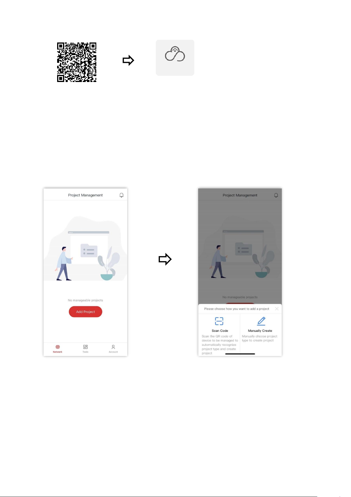
1. Scan the following QR code or search for the IP-COM IMS app (app v1.3.1 is used for
illustration below) in App Store or the app market to download and install the IP-COM IMS app
on your mobile phone.
Page 51
Version 1.0
Chapter 9 Device management 45
2. Log in to the IP-COM IMS app. On the Network page, add a Traditional WLAN project.
- Scan Code (recommended): Scan the Scan to Add Device QR code on the Ethernet port
surface of the switch to automatically recognize project type and create project.
- Manually Create: Manually choose project type and create project.
Scan Code method is used for illustration below.
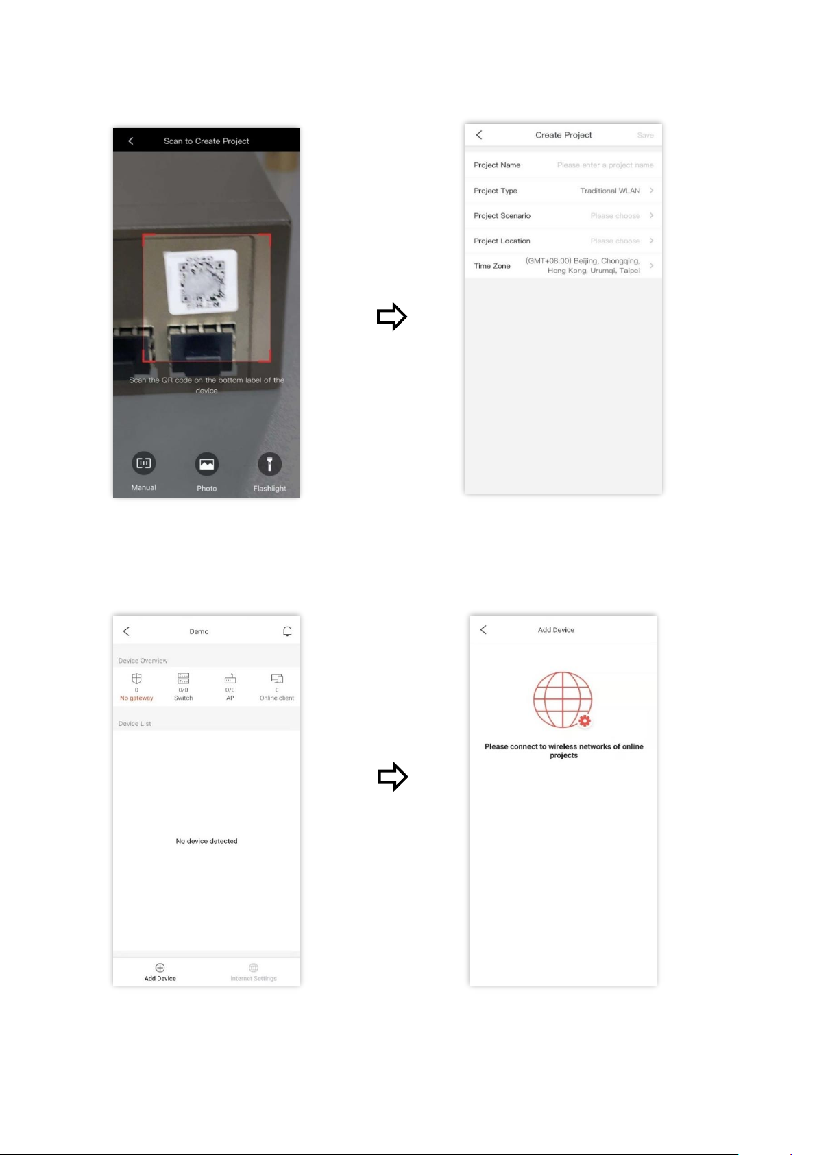
(1) Create project.
Click Add Project Click Scan Code
IP-COM IMS
Page 52
Version 1.0
Chapter 9 Device management 46
Scan the QR code on the switch Project type is automatically recognized
Set other project parameters and click Save ✓ Project created
(2) Add device.
Enter the project, click Add Device. The following prompt appears
Page 53
Version 1.0
Chapter 9 Device management 47
✓ The switch is added successfully
----End
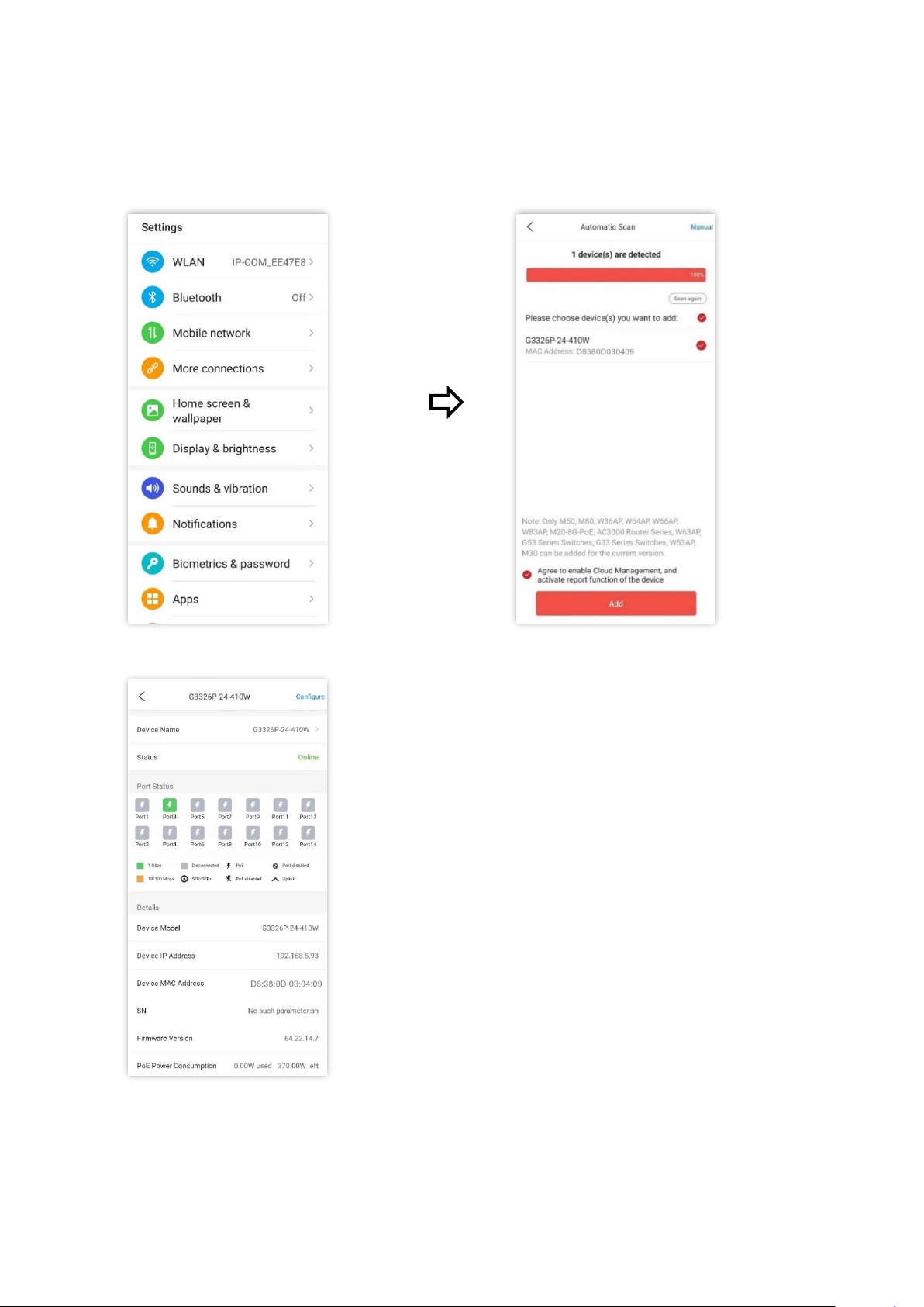
You can manage and maintain the switch on IP-COM IMS app.
On the Settings page, connect to the
WiFi network of the LAN where this
switch is deployed (this WiFi network
should have internet access)
Go back to the app. Wait until the
switch to be added is automatically
detected, tick the switch, and tick
Agree to enable Cloud Management,
and activate report function of the
device to add the switch
Page 54
Version 1.0
Chapter 10 Configuration 48
10 Configuration
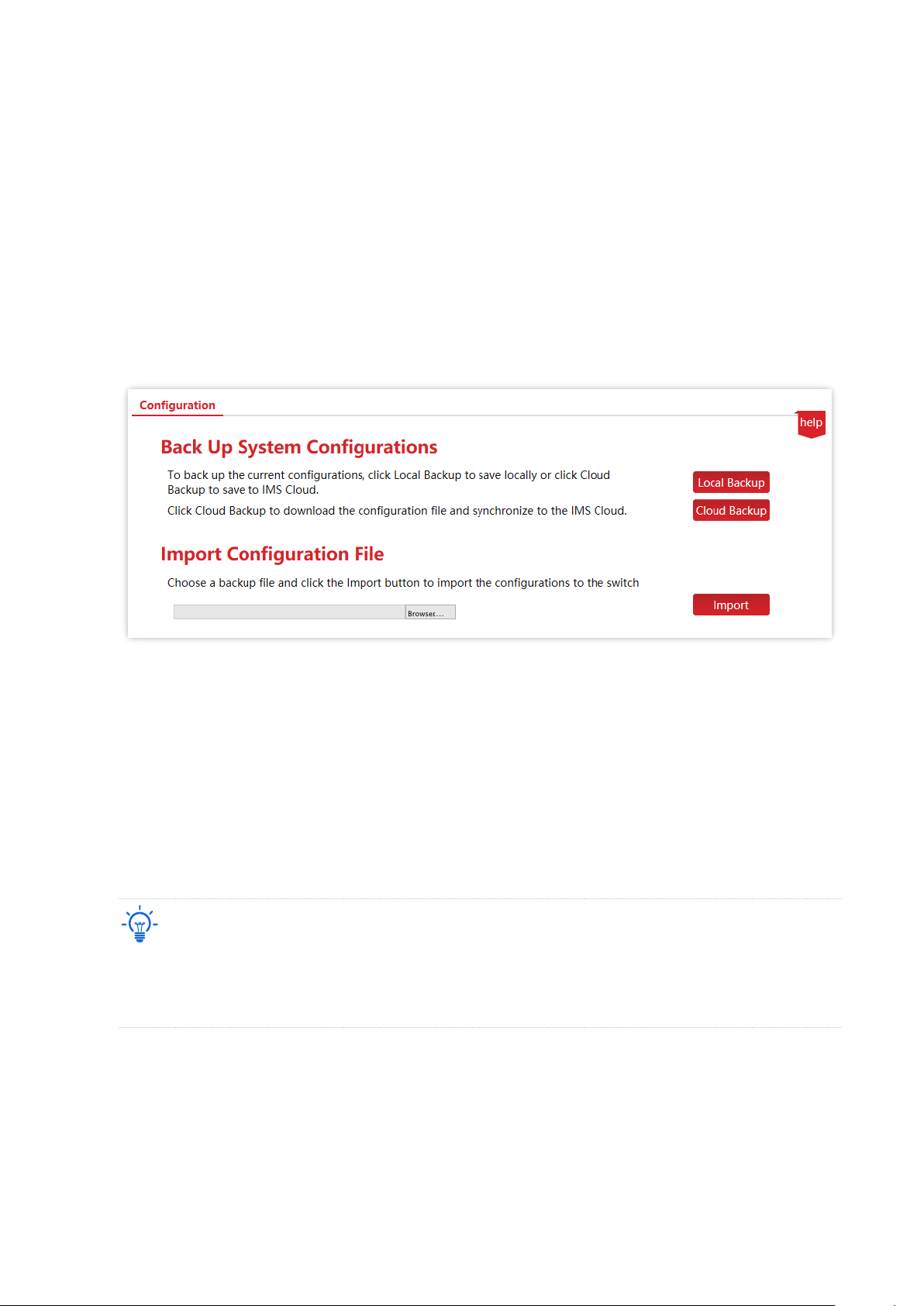
Click Configuration to enter the page. On this page, you can back up system configurations and
import configuration files.
10.1 Back up system configurations
If you have made configurations to the switch for better performance, it is recommended to
back up the configurations. After you upgrade the switch or restore the switch to factory
settings, you can import this backup configuration file to restore the configurations to the
switch.
The switch supports two backup methods: local backup and cloud backup.
Tip
− Please click Save on the upper right corner of the page to save all settings before backup.
− Only when the switch is managed by the IMS cloud platform can the configurations be backed up to the
IMS cloud platform.
10.2 Import configuration file
If you need to make same configuration on several switches, or performance degradation of
Page 55

Version 1.0
Chapter 10 Configuration 49
switch occurs due to wrong operations, you can click Import to import the backup
configuration file to the switch.
Page 56

Version 1.0
Appendix 50
Appendix
Acronyms and Abbreviations
Acronym or Abbreviation
Full Spelling
BPDU
Bridge Protocol Data Unit
CRC
Cyclic Redundancy Check
DA
Destination Address
DHCP
Dynamic Host Configuration Protocol
DNS
Domain Name System
FDX
Full Duplex
FIFO
First Input First Output
HDX
Half Duplex
IP
Internet Protocol
LAN
Local Area Network
MAC
Medium Access Control
PoE
Power over Ethernet
PVID
Port-based VLAN ID
QoS
Quality of Service
RSTP
Rapid Spanning Tree Protocol
SA
Source Address
SP
Strict Priority
STP
Spanning Tree Protocol
TTL
Time to Live
VLAN
Virtual Local Area Network
WAN
Wide Area Network
WRR
Weighted Round Robin
Page 57
Version 1.0
Appendix 51
Configure the switch to access the internet
Networking requirement
You want to configure the switch to access the internet.
Tip
The following shows the steps to access the internet when the switch’s DHCP client is disabled.
(When the DHCP client is enabled, the switch automatically obtains IP address and other parameters from
the upstream router.)
Assume that:
− LAN IP address/subnet mask of the upstream router: 192.168.1.1/255.255.255.0
− Primary & secondary DNS server address: 192.168.108.108, 192.168.108.110
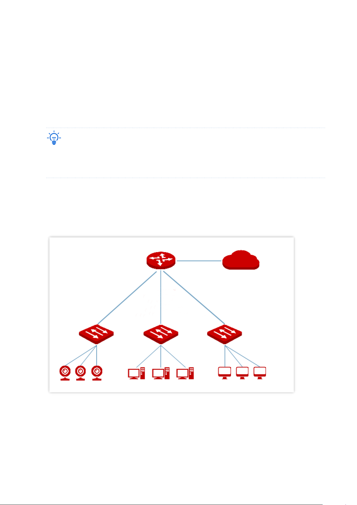
The network topology is as shown below.
Configuration procedure
1. Log in to the web UI of the switch.
2.
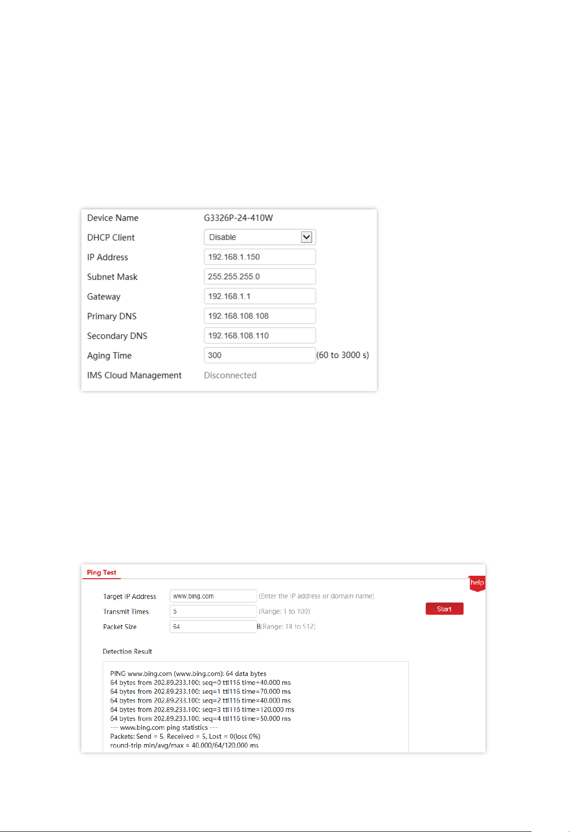
Configure the IP address, subnet mask, gateway and DNS server addresses of the switch.
Router
Internet
Surveillance network
Office area
Meeting room
This switch
This switch
This switch
LAN port
WAN port
Page 58
Version 1.0
Appendix 52
(1)
Click System Management > System Info.
(2) Set IP Address to an IP address in the same network segment as that of the LAN IP
address of the router, which is 192.168.1.150 in this example.
(3) Set Subnet Mask to 255.255.255.0, Gateway to 192.168.1.1.
(4) Set the Primary DNS and Secondary DNS to DNS server addresses that can properly
resolve the URL of the IMS cloud platform, which are 192.168.108.108, 192.168.108.110
respectively in this example.
(5) Click Apply.
----End
Verification
After configuration, you can test whether the switch can access the internet through the Ping
test on Device Management > Diagnosis page.
You can ping a domain name to test the internet connection status, which is www.bing.com in
this example. The switch accesses the internet successfully if the test results are as shown
below.
 Loading...