

Page 1
i
1 Product Overview
Page 2

ii
1 Product Overview
Copyright Statement
©2015 IP-COM Networks Co., Ltd. All rights reserved.
IP-COM is the registered trademark of IP-COM Networks Co., Ltd. Other brand and product
names mentioned herein are trademarks or registered trademarks of their respective holders.
Copyright of the whole product as integration, including its accessories and software, belongs to
IP-COM Networks Co., Ltd. No part of this publication can be reproduced, transmitted,
transcribed, stored in a retrieval system, or translated into any language in any form or by any
means without the prior written permission of IP-COM Networks Co., Ltd.
Disclaimer
Pictures, images and product specifications herein are for references only. To improve internal
design, operational function, and/or reliability, IP-COM reserves the right to make changes to the
products described in this document without obligation to notify any person or organization of
such revisions or changes. IP-COM does not assume any liability that may occur due to the use or
application of the product or circuit layout(s) described herein. Every effort has been made in the
preparation of this document to ensure accuracy of the contents, but all statements, information
and recommendations in this document do not constitute the warranty of any kind, express or
implied.
Page 3

iii
1 Product Overview
Conventions
Thank you for choosing IP-COM! Please read this user guide before you start. This user guide
instructs you to install and configure the AP.
Typographical conventions in this User Guide:
Item
Presentation
Example
Button
Bold
“Click the Save button” can be simplified as
“Click Save”.
Menu
Bold
“The menu Basic” can be simplified as Basic.
Continuous Steps
>
Click Wireless > Basic
Symbols in this User Guide:
Item
Meaning
Note
This format is used to highlight information of importance or special
interest. Ignoring this type of note may result in ineffective
configurations, loss of data or damage to device.
Tip
This format is used to highlight a procedure that will save time or
resources.
Technical Support
Tel: (86755) 2765 3089
Email: info@ip-com.com.cn
Website: http://www.ip-com.com.cn
Page 4

iv
1 Product Overview
Contents
1 Product Overview .......................................................................................................................... 1
Package Contents ................................................................................................................................. 1
Hardware Description .......................................................................................................................... 2
Front View ........................................................................................................................................ 2
Rear View ......................................................................................................................................... 3
Label ................................................................................................................................................ 4
2 Quick Installation Guide ............................................................................................................... 5
Step 1: Connect an Ethernet Cable to the AP ....................................................................................... 5
Step 2: Mount the AP ........................................................................................................................... 5
Step 3: Connect the AP ......................................................................................................................... 6
Step 4: Configure Your AP ................................................................................................................... 7
AP Mode .......................................................................................................................................... 7
WDS Mode ...................................................................................................................................... 9
AP Client Mode .............................................................................................................................. 13
3 More Features .............................................................................................................................. 16
Status .................................................................................................................................................. 16
System Status ................................................................................................................................. 16
Wireless Status ............................................................................................................................... 17
Traffic Statistics ............................................................................................................................. 17
Wireless Clients.............................................................................................................................. 18
Quick Setup ........................................................................................................................................ 18
Network .............................................................................................................................................. 18
LAN Setup ..................................................................................................................................... 19
DHCP Server .................................................................................................................................. 21
Wireless .............................................................................................................................................. 23
Basic ............................................................................................................................................... 23
Radio .............................................................................................................................................. 31
Channel Scan.................................................................................................................................. 32
Advanced ....................................................................................................................................... 33
Access Control ............................................................................................................................... 35
QVLAN .......................................................................................................................................... 36
SNMP ................................................................................................................................................. 39
Deployment ........................................................................................................................................ 40
Tools ................................................................................................................................................... 42
Maintenance ................................................................................................................................... 42
Time & Date ................................................................................................................................... 43
Logs................................................................................................................................................ 46
Configuration ................................................................................................................................. 49
User Name & Password ................................................................................................................. 51
Diagnostics ..................................................................................................................................... 52
Page 5

v
1 Product Overview
Reboot ............................................................................................................................................ 52
LED ................................................................................................................................................ 55
Uplink Detection ............................................................................................................................ 56
Appendix ......................................................................................................................................... 57
1 Configure PC ................................................................................................................................... 57
Windows 8 ..................................................................................................................................... 57
Windows 7 ..................................................................................................................................... 59
Windows XP .................................................................................................................................. 61
2 Factory Defaults .............................................................................................................................. 63
3 FAQs ............................................................................................................................................... 64
4 Safety and Emission Statement ....................................................................................................... 65
Page 6

1
1 Product Overview
1 Product Overview
IP-COM AP515, with its external power amplifier and 7dBi directional antennas, offers bandwidth
of up to 300Mbps on 2.4GHz band. Its waterproof housing and flexible mounting design makes it
suitable for different harsh environments such as high/low temperature, humidity, rainfall, dust,
frost, etc. It is compatible with standard IEEE 802.3at and can be managed by IP-COM ACs. It
provides optimal outdoor WiFi coverage for hospitals, campuses, commercial streets, stadiums
and other areas.
Package Contents
If any item is incorrect, missing, or damaged, please contact your dealer for immediate
replacement.
Page 7
2
1 Product Overview
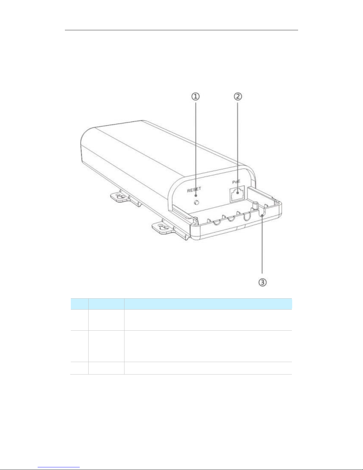
Hardware Description
Front View
Item
Port/Button
Description
1
RESET
Pressing and holding the reset button for over 7 seconds restores this
device to factory defaults.
2
PoE
This port provides power over an Ethernet connection via the PoE
injector or an IEEE802.3at-compliant PoE device. And it also works
as a 10/100/1000Mbps LAN port.
3 / Cable access hole cut-outs
Page 8

3
1 Product Overview
Rear View
LED
Status
Description
SYS
Blinking
The device is working properly.
Off
Malfunction occurs or the device is not powered on.
Solid
Malfunction occurs.
WiFi
Blinking
Data transmission is occurring.
Off
WiFi is disabled.
Solid
WiFi is enabled.
LAN
Blinking
Data transmission is occurring on the LAN port.
Off
There is no device linked to this port.
Solid
There is a device linked to this port but no data transmission.
Control
Solid
The device is managed by an AC successfully.
Off
The device isn’t managed by an AC.
Page 9
4
1 Product Overview
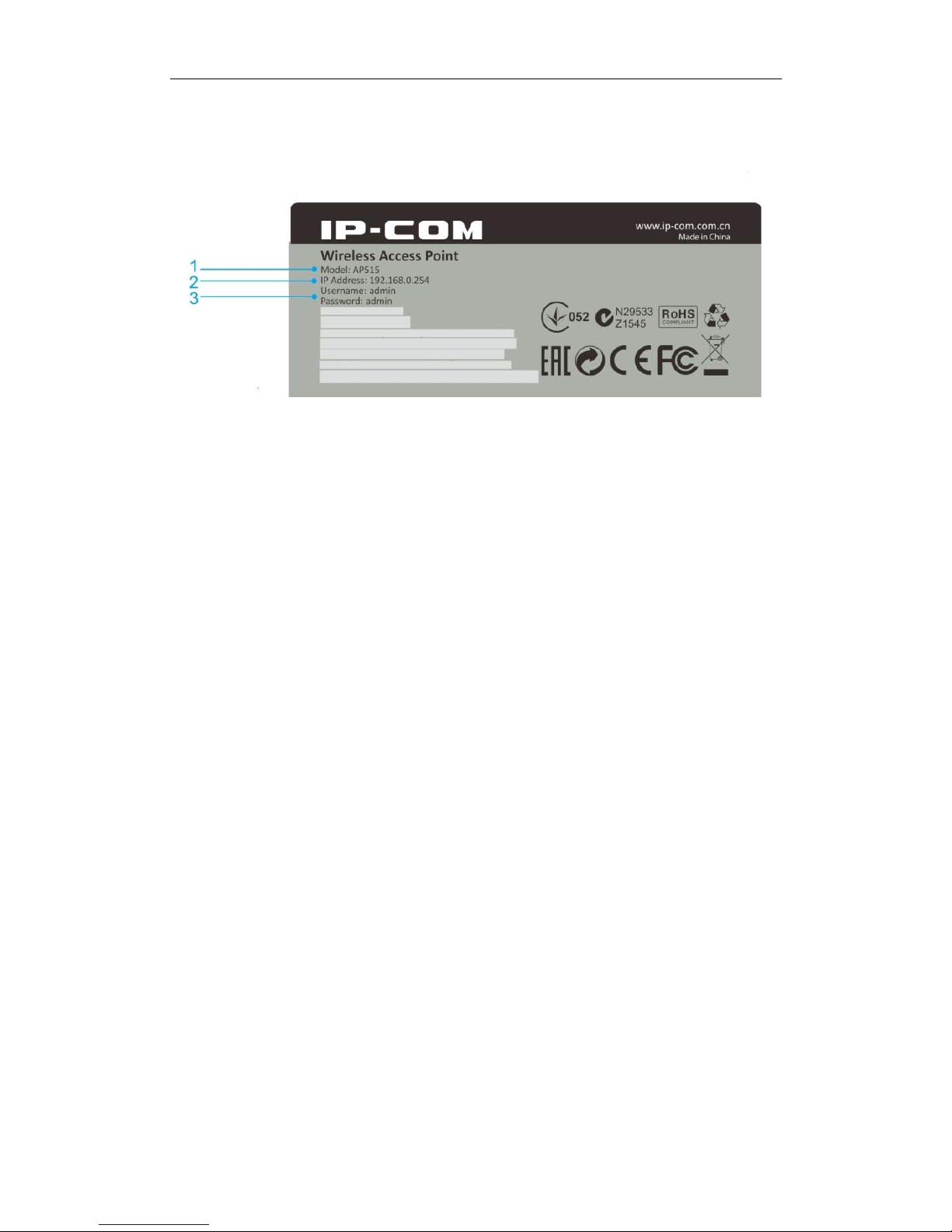
Label
1. Model: Product model of the AP.
2. IP Address: Default login IP address (management IP) of this AP.
3. Username/Password: Default login user name and password.
Page 10
5
2 Quick Installation Guide
2 Quick Installation Guide
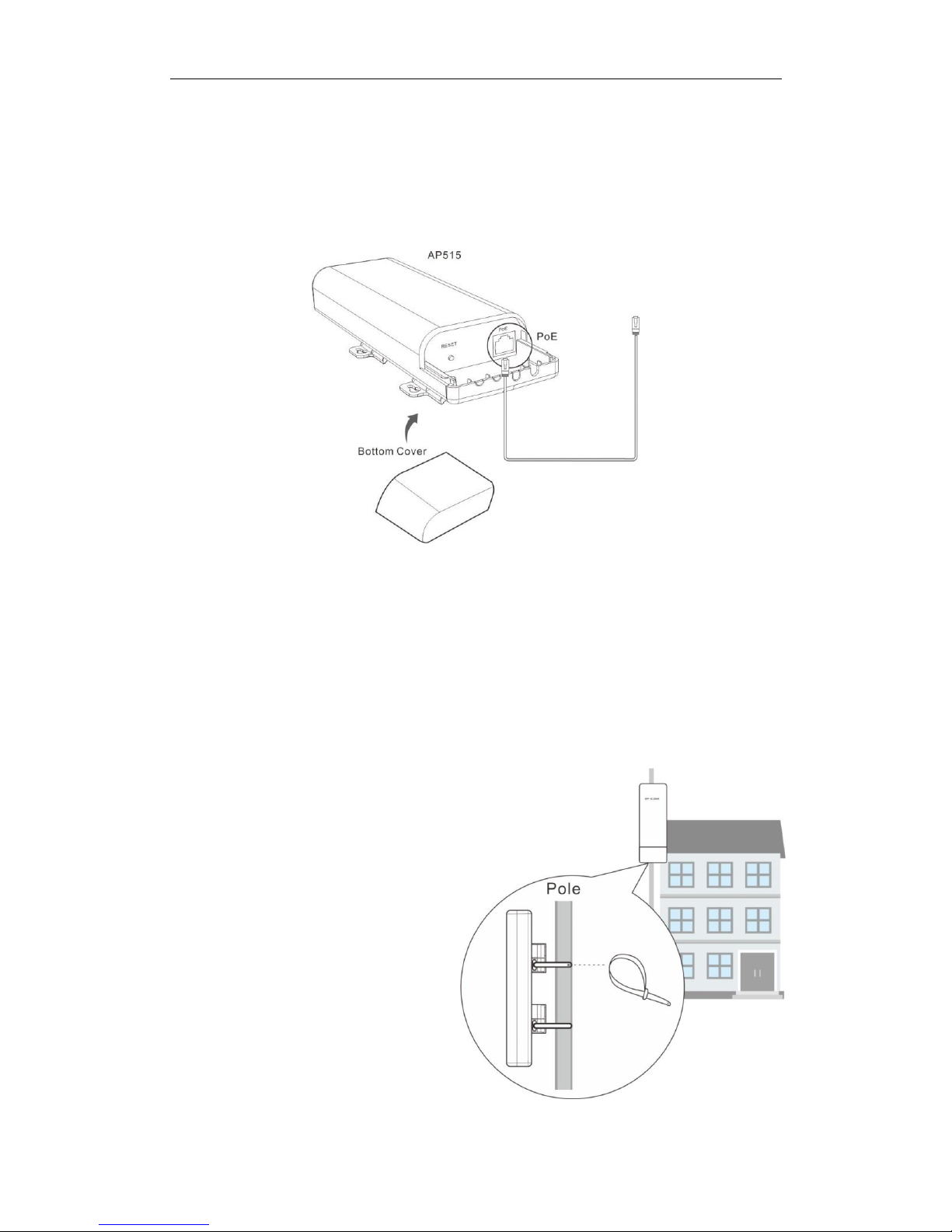
Step 1: Connect an Ethernet Cable to the AP
❶ Slide the bottom cover of the AP down to expose the port.
❷ Connect an Ethernet cable (≤ 60m), which will be connected to the PoE injector or a PoE
switch, to the PoE port of your AP.
❸ Gently replace the cover by sliding it up until it clicks into place.
Step 2: Mount the AP
Set up the AP in an outdoor location, usually
on the roof, and thread plastic wraps
through grooves underneath the brackets.
Then attach the device firmly to a solid pole.
Page 11
6
2 Quick Installation Guide
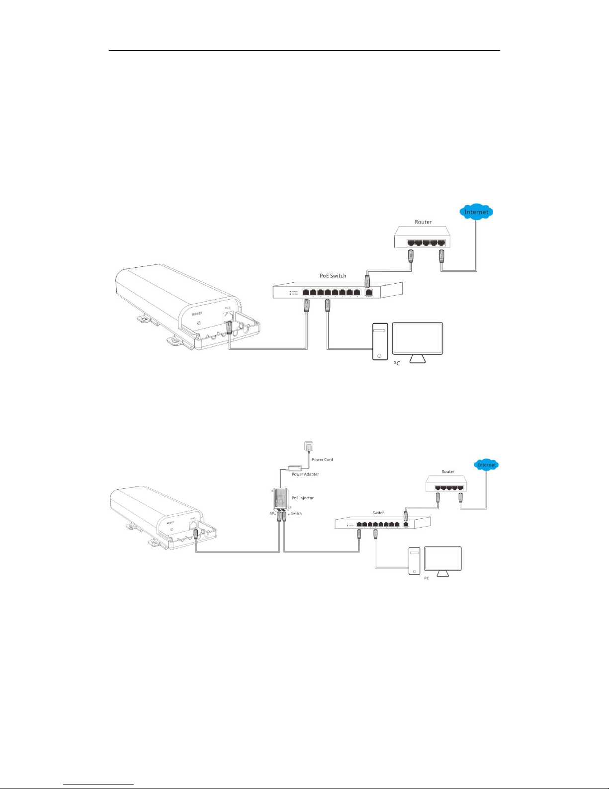
Step 3: Connect the AP
As you can connect your AP to a PoE switch or with the included PoE injector for power supply,
two methods are available here to connect your AP. Select the proper method according to your
needs.
With a PoE switch for power supply
❶ Connect the Ethernet cable, which has been connected to the AP in Step 1, to a PoE switch.
❷ Connect your PC or other Ethernet devices to the PoE switch with Ethernet cables.
With the included PoE injector for power supply
❶ Connect the Ethernet cable, which has been connected to the AP in Step 1, to the AP port of
the PoE injector.
❷ Connect a switch to the Switch port of the PoE injector with an Ethernet cable.
❸ Connect the included power adapter to the PoE injector, connect the power adapter to the
included power cord and plug the power cord into an outlet for power supply.
❹ Connect your PC or other Ethernet devices to the switch with Ethernet cables.
Page 12
7
2 Quick Installation Guide
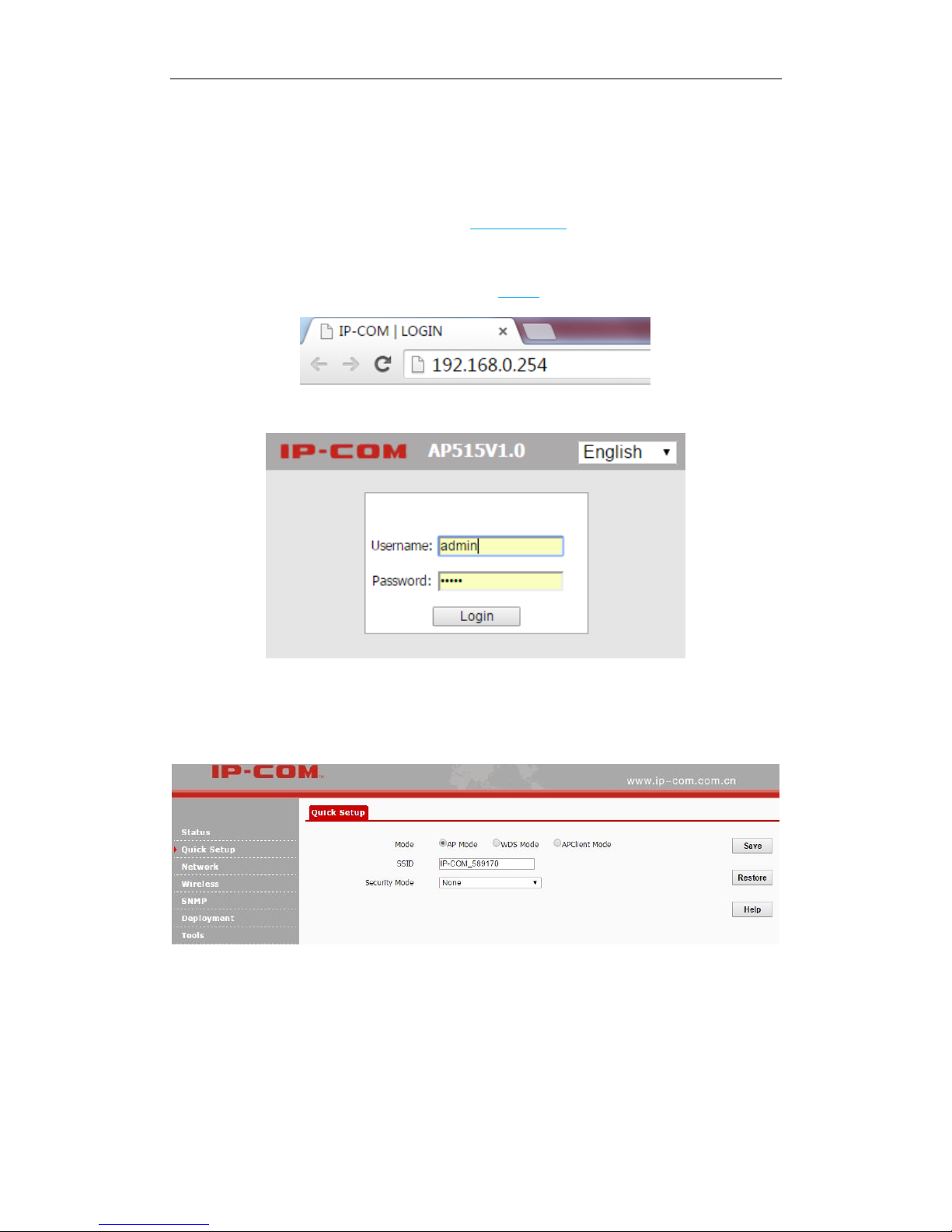
Step 4: Configure Your AP
1. Set your PC to Use the following IP address: IP address: 192.168.0.x (2~253); subnet mask:
255.255.255.0. For specific steps, see Appendix 1 Configure PC.
2. Input 192.168.0.254 in a web browser’s address bar, and then press Enter or Return on your
keyboard (If the following page does not appear, see FAQ 1).
3. Enter the default username and password (admin for both defaults) and click Login.
4. Then you will be successfully directed to the web UI of the AP. Click Quick Setup to select the
proper operating mode and complete corresponding mode settings. 3 operating modes are
supported on this AP: AP mode, WDS mode and AP Client mode.
AP Mode
In this mode, the device can be connected to a wired network and transform the wired access into
wireless that multiple devices can share together.
Page 13

8
2 Quick Installation Guide
Application Scenario:
Network Topology:
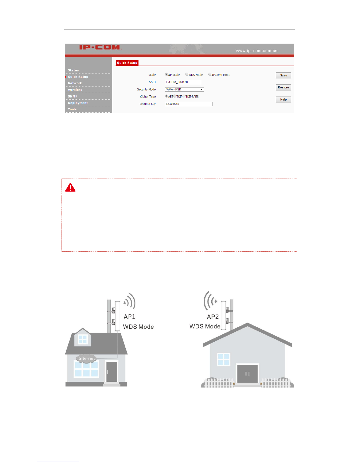
Configuration Steps: (In this example, WPA -PSK and AES are taken for illustration. For other
security modes, see Basic.)
❶ Select AP Mode.
❷ Customize your SSID (WiFi name). This is optional.
❸ Set the security mode, say WPA-PSK.
❹ Select AES as its cypher type.
❺ Set a security key (WiFi password), which you’ll need when you’re connecting to your SSID.
❻ Click Save to apply your settings.
Page 14
9
2 Quick Installation Guide
WDS Mode
In this mode, the AP is used for building a wireless distribution system for WiFi coverage and
WiFi extension.
Note:
In the WDS mode, both the AP and the remote device should support WDS feature.
As for IP addresses, they should not be the same but on the same network segment.
This AP’s and the remote device’s SSIDs, channels, security modes and security keys should
be kept the same.
One-to-one WDS
Application Scenario:
Page 15

10
2 Quick Installation Guide
Network Topology:
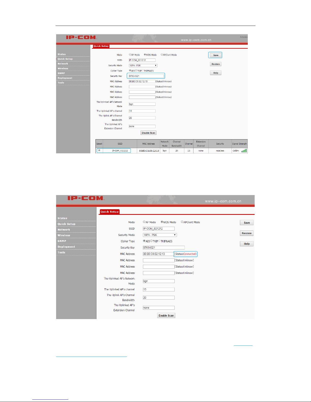
Configuration Steps:
Step 1: Log in to the web UI of AP1 and note down the basic info of AP1 as shown below:
IP Address: 192.168.0.254
SSID: IP-COM_021212
Security Mode: WPA-PSK
Security Key (WiFi Password): 86754321
Step 2: Log in to the web UI of AP2 and change its LAN IP address to one that is different from
that of AP2 but on the same network segment, such as 192.168.0.253. For details, see LAN Setup.
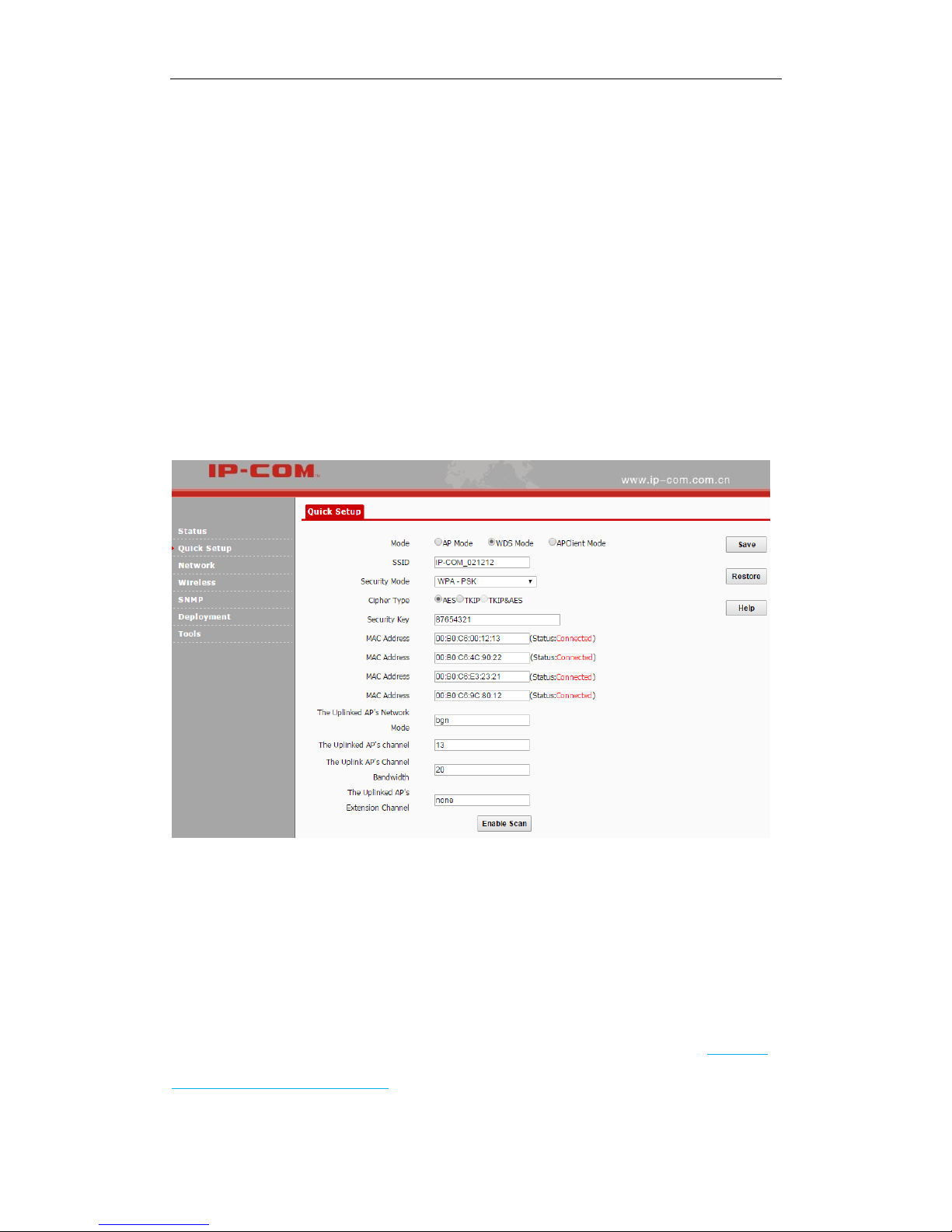
Step 3: Configure WDS settings on AP2.
❶ Click Quick Setup, select WDS Mode and click Enable Scan.
❷ Select the SSID of AP1 from the list, say, IP-COM_021212.
❸ Enter the security key (WiFi password) of AP1 in the Security Key field. Here we say
87654321.
❹ Click Save to apply your changes. Then the SSID of AP2 will be kept the same as that of AP1
automatically.
Page 16
11
2 Quick Installation Guide
Step 4: Login to the web manager of AP1, refer to ❶~❹ of Step 3 to configure WDS settings
on AP1.
When the status of the MAC address displays Connected, they have been bridged successfully.
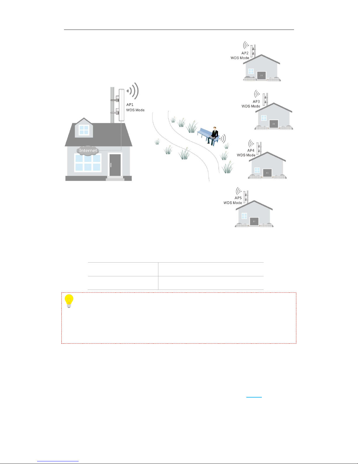
One-to-many (≤4) WDS
The typical application scenario is shown as below. As for its network topology, refer to Network
topology in one-to-one WDS mode.
Page 17
12
2 Quick Installation Guide
Configuration Steps:
Step 1: Log in to the web UI of AP1 and note down its basic information as shown below:
IP Address: 192.168.0.254
SSID: IP-COM_021212
Security Mode: WPA-PSK
Security Key (WiFi password): 87654321
Tip
IP addresses of AP2, AP3, AP4 and AP5 should be different from that of AP1 but on the same
network segment. For example, you can set them to 192.168.0.2, 192.168.0.3, 192.168.0.4 and
192.168.0.5 respectively.
Step 2: Log in to the web UI of AP2, AP3, AP4 and AP5 respectively, change their LAN IP
addresses (AP2: 192.168.0.2, AP3: 192.168.0.3, AP4: 192.168.0.4, AP5: 192.168.0.5) and keep
their security info and channels the same as that of AP1.
Step 3: Log in to web UI of AP2, AP3, AP4 and AP5 respectively and refer to Step 3 in
One-to-One WDS part to bridge them with AP1.
Page 18
13
2 Quick Installation Guide
Step 4: Log in to the web UI of AP1 and configure WDS settings to bridge itself with AP2, AP3,
AP4 and AP5 respectively.
❶ Click Quick Setup, select WDS Mode and click Enable Scan.
❷ Locate SSIDs of AP2, AP3, AP4 and AP5 in the list, and then select them one by one (At this
time, SSIDs of AP2, AP3, AP4 and AP5 have been changed into the SSID of AP1, i.e.
IP-COM_021212).
❸ Enter the security key (WiFi password) of AP1 in the Security Key field, say 87654321.
❹ Click Save to complete your settings.
When status of corresponding MAC addresses displays Connected, they’ve bridged successfully.
AP Client Mode
In this mode, the device extends the wireless coverage of another wireless AP or router. The
advantage of the AP client mode is that the remote device does not need to have WDS function
and may not need to be the same brand. Therefore, it can work with almost any wireless device.
Its typical application scenario is shown as below. As for its network topology, refer to Neowork
topology in one-to-one WDS mode.
Page 19

14
2 Quick Installation Guide
Configuration Steps:
❶ Log in to the web UI of AP1 and note down its basic information as shown below:
IP Address: 192.168.0.254
SSID: IP-COM_021212
Security Mode: WPA-PSK
Security Key (WiFi Password): 87654321
❷ Log in to the web UI of AP2 and change its LAN IP address to one that is different from that
of AP1 but on the same network segment, say 192.168.0.253. For details, see LAN Setup.
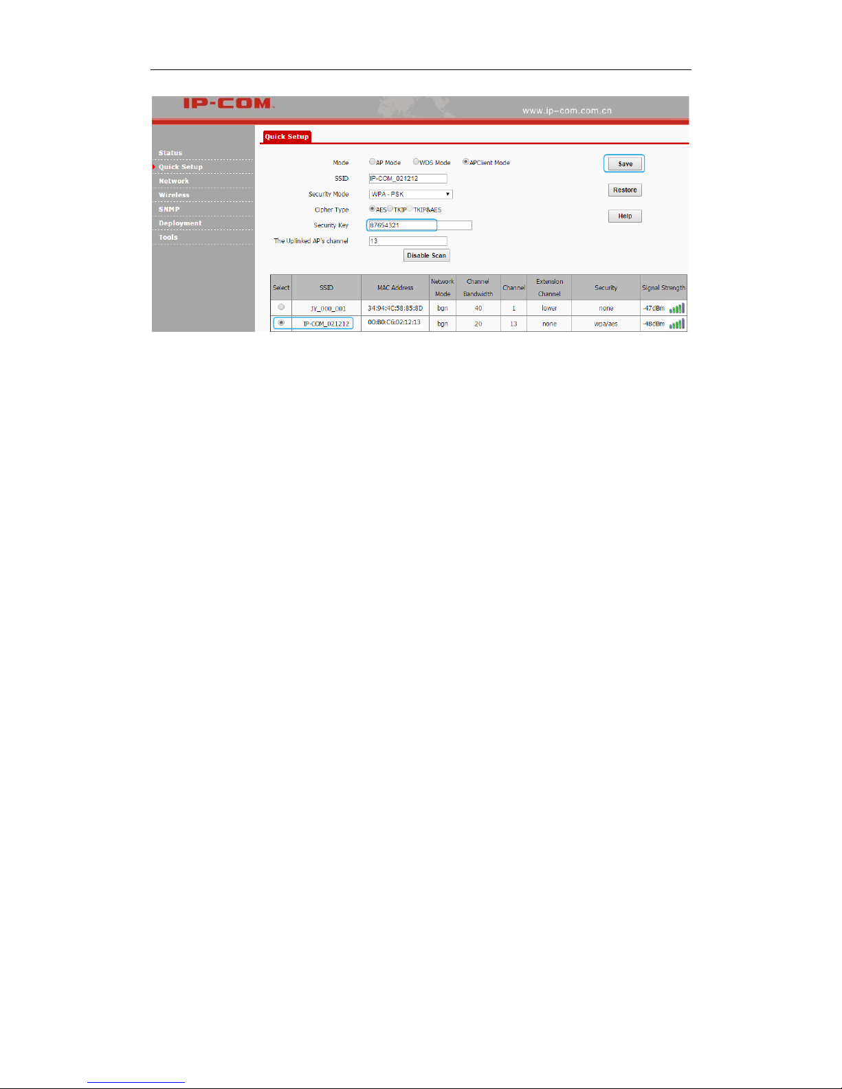
❸ Click Quick Setup, select APClient Mode and click Enable Scan.
❹ Locate and select the SSID of AP1 from the list, say IP-COM_021212.
❺ Enter the security key (WiFi password) of AP1 in the Security Key field.
❻ Click Save to apply your settings.
Page 20
15
2 Quick Installation Guide
When AP2 and AP1 are bridged successfully, wireless devices, like smart phones, can connect to
the WiFi of AP2 for Internet access.
Page 21
16
3 More Features
3 More Features
Status
This section gives you an overview of device status and basic information. The following parts are
included:
System Status: Display the AP’s current system status and LAN information.
Wireless Status: Display connected devices’ radio status and SSID status information.
Traffic Statistics: Display traffic statistics of all SSIDs.
Wireless Clients: Display information of connected devices.
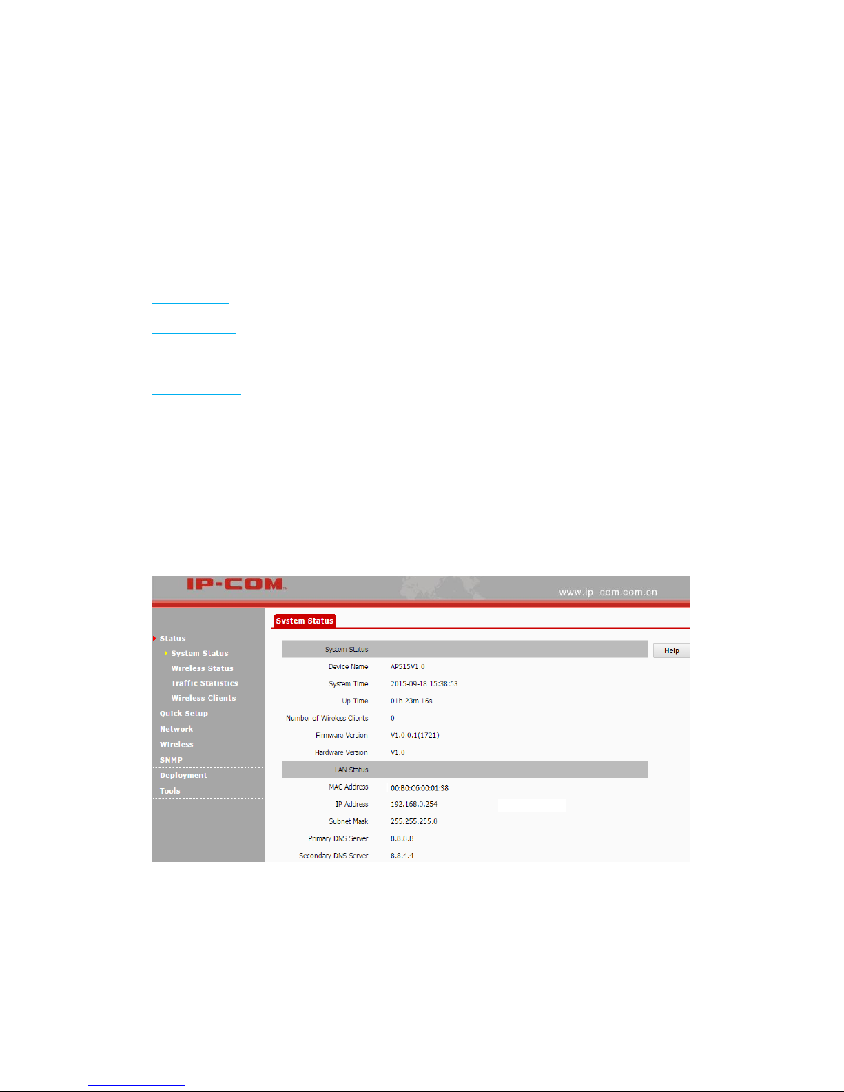
System Status
This page displays system status information and LAN information of this AP, including device
name, system time, up time, number of wireless clients, firmware version, hardware version,
MAC address, IP address, etc.
Page 22
17
3 More Features
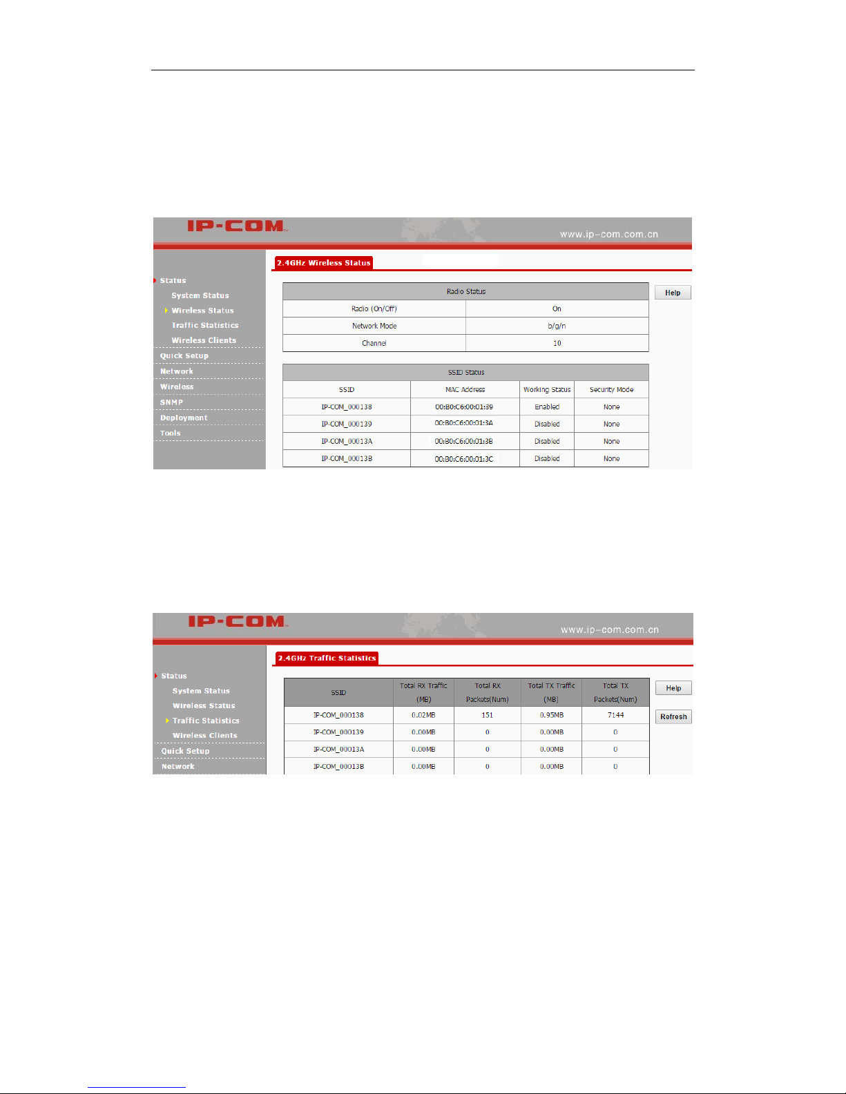
Wireless Status
This page displays 2.4GHz radio status, SSID status and WDS status of this device. Click Status >
Wireless Status to enter page below:
Traffic Statistics
This page displays traffic statistics of corresponding SSIDs. Click Status > Traffic Statistics to
enter page below:
Parameters on this page are described below:
SSID: WiFi name.
Total RX Traffic: Total traffic which the corresponding SSID has received.
Total RX Packets: Total packets which the corresponding SSID has received.
Total TX Traffic: Total traffic which the corresponding SSID has transmitted.
Total TX Packets: Total packets the corresponding SSID has transmitted.
Page 23
18
3 More Features
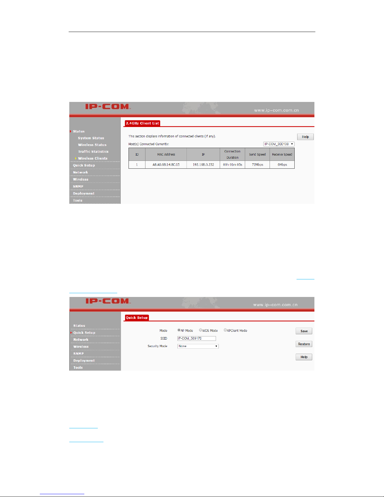
Wireless Clients
This page displays information, like MAC address, IP, connection duration and link speed of
connected clients. Click Status > Wireless Clients to enter page below:
Quick Setup
This section mainly walks you through operating modes of the AP. Click Quick Setup to enter
page below and you can select the proper operating mode in terms of your network environment.
For specific configuration steps and application scenarios of different operating modes, see Step 4:
Configure Your AP.
Network
Two parts are included for this section:
LAN Setup: Display the AP’s MAC address and configure its device name and IP info.
DHCP Server: Include DHCP server and DHCP client list.
Page 24
19
3 More Features
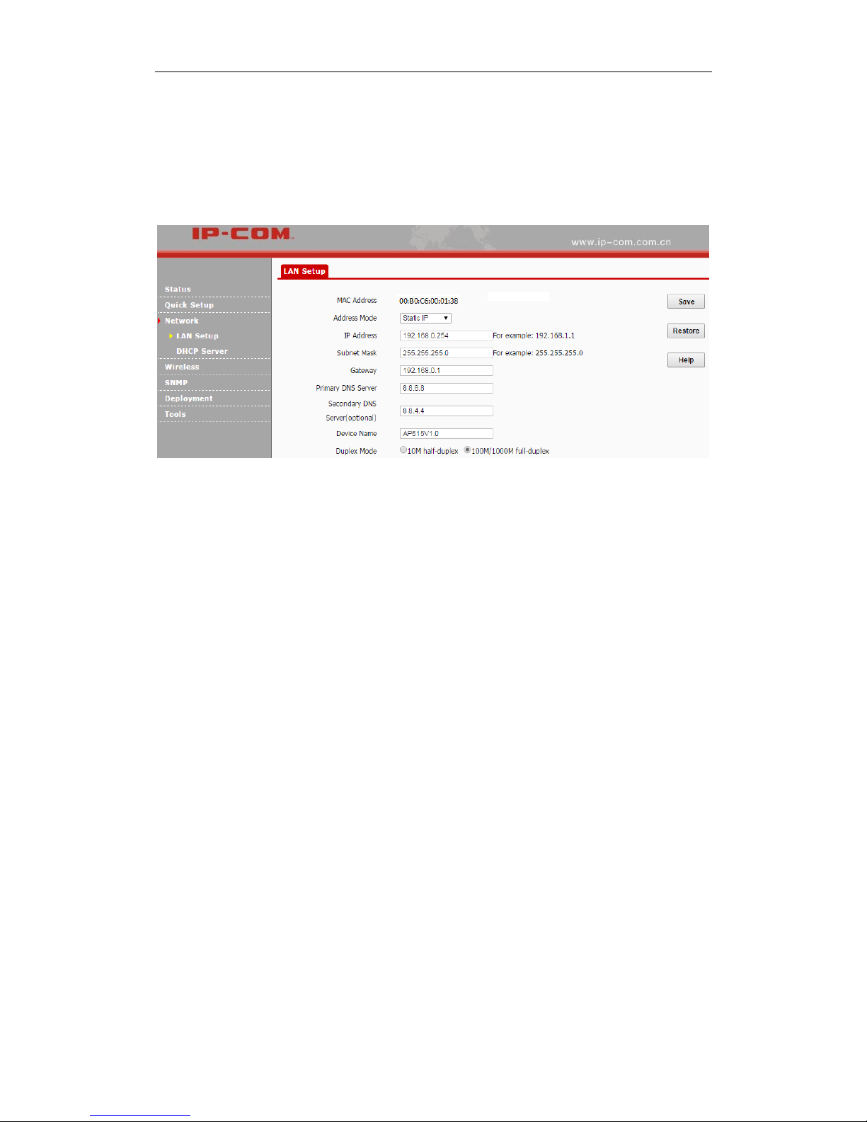
LAN Setup
You can choose whether the AP gets its IP address manually (static IP) or automatically (DHCP).
Click Network > LAN Setup to enter page below:
Parameters on this page are described below:
MAC Address: LAN MAC address of the device.
Address Mode: Static IP: The default address mode of your device. You can modify the
LAN IP address manually. Once the LAN IP address of the device is changed, you need to
use the new IP address to re-log in to its web page. Dynamic IP: Your device obtains IP
address information automatically.
IP Address: The default LAN IP address of the device is 192.168.0.254. You can modify it
here.
Subnet Mask: Subnet mask of the device. The default one is 255.255.255.0.
Gateway: Gateway of the device. Usually, it is advisable to enter the LAN IP address of the
remote device.
Primary DNS Server: Enter the necessary DNS address provided by your ISP (This field
cannot be blank). Consult your ISP if you are not clear.
Secondary DNS Server: Enter the other DNS address if your ISP offers you two DNS
addresses (This field is optional).
Device Name: Modify the device name.
Page 25

20
3 More Features
Duplex Mode: Transmission distance of its RJ45 port. The default value is 100M/1000M
full-duplex. The faster the auto-negotiation speed is, the shorter the transmission distance will
be. When the AP can’t communicate with its remote device, it is advisable to select 10M
half-duplex mode.
To set your AP’s IP address in Static IP mode:
❶ Address Mode: Select Static IP.
❷ IP Address: Enter a unique IP address that will be used to login to this AP’s web UI.
❸ Subnet Mask: Enter the subnet mask of your network.
❹ Gateway: Enter the IP address of the default gateway for your network.
❺ Primary DNS Server: Specify the IP address of the preferred DNS (Domain Name System)
server.
❻ Secondary DNS Server: Specify the IP address of the alternate DNS server. This entry is
optional and used only if the primary DNS server is not responding.
❼ Click Save to apply your changes.
Note:
In static IP address mode, once you’ve changed your LAN IP address, you need to use the new IP
address to login to its web UI .
Page 26

21
3 More Features
To set your AP’s IP address in DHCP mode:
❶ Address Mode: Select Dynamic IP.
❷ Click Save to apply your changes.
Note:
In DHCP mode, your LAN IP address is assigned by the DHCP server of your uplink device.
Thus, to know your LAN IP address, you need to check it on the DHCP client list of the uplink
device.
DHCP Server
DHCP Server
If you enable the built-in DHCP server on the device, it will automatically configure the TCP/IP
settings for all your LAN computers (including IP address, subnet mask, gateway and DNS etc.),
eliminating the need of manual intervention. Just be sure to set all computers on your LAN to be
DHCP clients by selecting Obtain an IP Address Automatically respectively on each PC. When
turned on, these PCs will automatically load IP information from the DHCP server. By default, the
DHCP server on this device is disabled. The first time you connected to the AP, you need to set
your PC to Use the following IP address. For more details, see Appendix 1 Configure PC.
Click Network > DHCP Server to enter page below:
Page 27

22
3 More Features
Some parameters are described below:
DHCP Server: Check/Uncheck it to enable/disable the DHCP server.
Start IP: The start IP address that the DHCP server has automatically assigned.
End IP: The end IP address that the DHCP server has automatically assigned.
Lease Time: How long the IP address can be used by the client device.
Primary DNS Server: Primary DNS server address.
Secondary DNS Server: Secondary DNS server address.
DHCP Client List
Click Network > DHCP Server > DHCP Client List to view DHCP clients information.
Page 28

23
3 More Features
Wireless
This section allows you to configure WLAN settings for your AP. Six parts are included:
Basic: Configure basic information for your AP, including SSID (WiFi name), clients, encryption
information, etc.
Radio: Configure wireless radio information for your AP, including Enable/Disable WiFi, network
mode, channel, etc.
Channel Scan: Scan wireless signals nearby.
Advanced: Adjust wireless performance for your device (For professional staff).
Access Control: Configure a list of devices to allow or disallow a connection to your WiFi via the
device's MAC addresses.
QVLAN: Configure QVLAN settings to secure your WiFi.
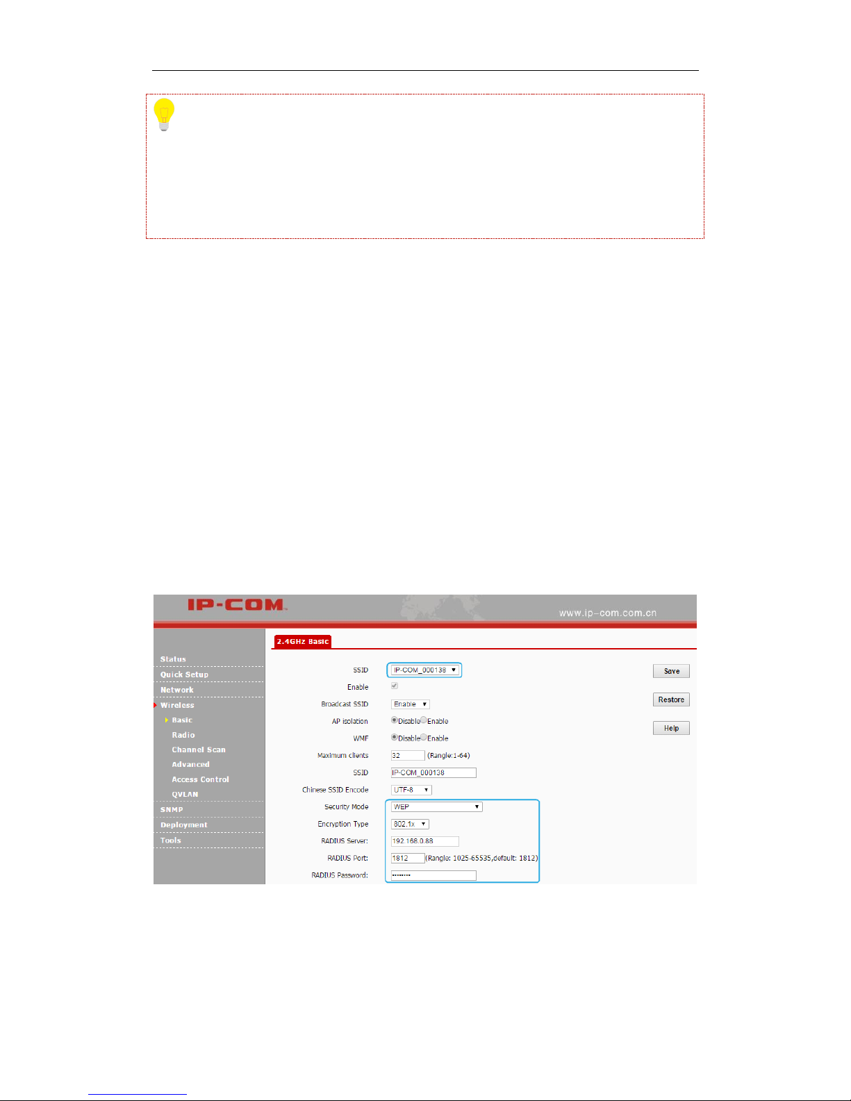
Basic
Click Wireless to configure basic wireless settings. It is advisable to configure the SSID, security
mode and security key, and leave other settings unchanged.
Parameters on this page are described below:
SSID: Up to 4 SSIDs at the 2.4G radio can be supported on this device.
Enable: When you check it, Wi-Fi will be allowed for the selected SSID.
Page 29

24
3 More Features
Broadcast SSID: When it is enabled, wireless clients are able to scan the SSID; when it is
disabled, wireless clients are unable to scan the SSID. At this time, if you want to connect to
it wirelessly, you have to type in the SSID and select the encryption mode manually.
AP Isolation: When this function is enabled, wireless clients connected to the SSID won’t be
able to communicate with each other, which can enhance wireless network security. When
this function is disabled, Wireless clients connected to the SSID are able to communicate
with each other.
WMF: Wireless Multicast Forwarding. Enabling this function will improve quality of
multicast data flow that wireless hosts have received.
Maximum Clients: The maximum number of wireless clients which can connect to the
SSID.
SSID: WiFi name. Different SSIDs can have different configurations.
Chinese SSID Encode: Select Chinese SSID encodes to match wireless clients with different
code formats in a better way. It is UTF-8 by default. If two or more SSIDs are enabled on this
AP, it is advisable to set some SSIDs to UTF-8 and set others to GB2312 so that any client
can recognize and connect to it.
Security Mode: Display wireless encryption information of the current SSID. Available
security modes are: None, WEP, WPA-PSK, WPA2-PSK, Mixed WPA/WPA2-PSK, WPA,
and WPA2.
WEP
WEP (Wired Equivalent Privacy): WEP is a security mode for data which is delivered between
two devices to protect wireless network from illegal users. Wireless speed can reach up to 54Mbps
if WEP is used.
Three encryption types are supported for WEP: Open, Shared and 802.1x.
Page 30

25
3 More Features
Configuration steps for Open or Shared: (In the example, the default key is Security Key 1 and
the WEP key 1 is 54321 and ASCII)
❶ Select the SSID you wish to encrypt, say, IP-COM_000138.
❷ Security Mode: Select WEP.
❸ Encryption Type: Select Shared or Open.
❹ Select Security Key 1 as the default key.
❺ Set WEP key 1 to 54321.
❻ Click Save to apply your changes.
Page 31
26
3 More Features
Tip
Most smart phones can only use WEP key 1 to connect to the WEP-encrypted (Open or Shared)
WiFi. When the security mode is WEP, and the encryption type is Open or Shared, to verify that
your smart phone can connect to the AP’s WiFi, you’d better select WEP Key 1 as the default key.
Configuration Steps for 802.1x: (In the example, the RADIUS server is 192.168.0.88, the
RADIUS port is 1812 and its password is 12345678)
❶ Select the SSID you wish to encrypt, say IP-COM_000138.
❷ Select WEP as its security mode.
❸ Select 802.1x as its encryption type,
❹ RADIUS Server: Enter 192.168.0.88.
❺ RADIUS Port: Enter 1812.
❻ RADIUS Password: Enter 12345678.
❼ Click Save to apply your changes.
Some parameters are described below:
Encryption Type: Select the encryption type for WEP: Open, Shared or 802.1x. The only
difference among them is the authentication type.
Page 32

27
3 More Features
Open: Use "no authentication" + WEP Encryption. Wireless clients can associate with the
device without going through authentication. Only data in transmission is encrypted with
WEP encryption.
Shared: Use shared key authentication + WEP Encryption. A WEP key that is mutually
agreed in advance is required from both sides while wireless clients try to associate with the
device. Association is established only if the two sides provide the same WEP key.
802.1x: Use 802.1x authentication + WEP encryption. When this option is selected, only
authenticated users can access the wireless network.
Default Key: Used for specifying the current WEP key (Open and Shared). If the default key
is WEP Key 2, wireless clients need to use WEP Key 2 to connect to the AP.
ASCII: 5~13 ASCII characters are supported.
Hex: 10 or 26 HEX characters (0~9, a~f, A~F) are supported.
RADIUS Server: The IP address of the RADIUS server for authentication in the LAN.
RADIUS Port: Port for RADIUS authentication.
RADIUS Password: Password for accessing the RADIUS server.
WPA-PSK, WPA2-PSK, Mixed WPA/WPA2-PSK
Wi-Fi Protected Access (WPA) and Wi-Fi Protected Access II (WPA2) are two security protocols
and security certification programs developed by the Wi-Fi Alliance to secure wireless computer
networks. Only authorized network users can access the wireless network. WPA-PSK adopts
enhanced encryption algorithm over WEP.
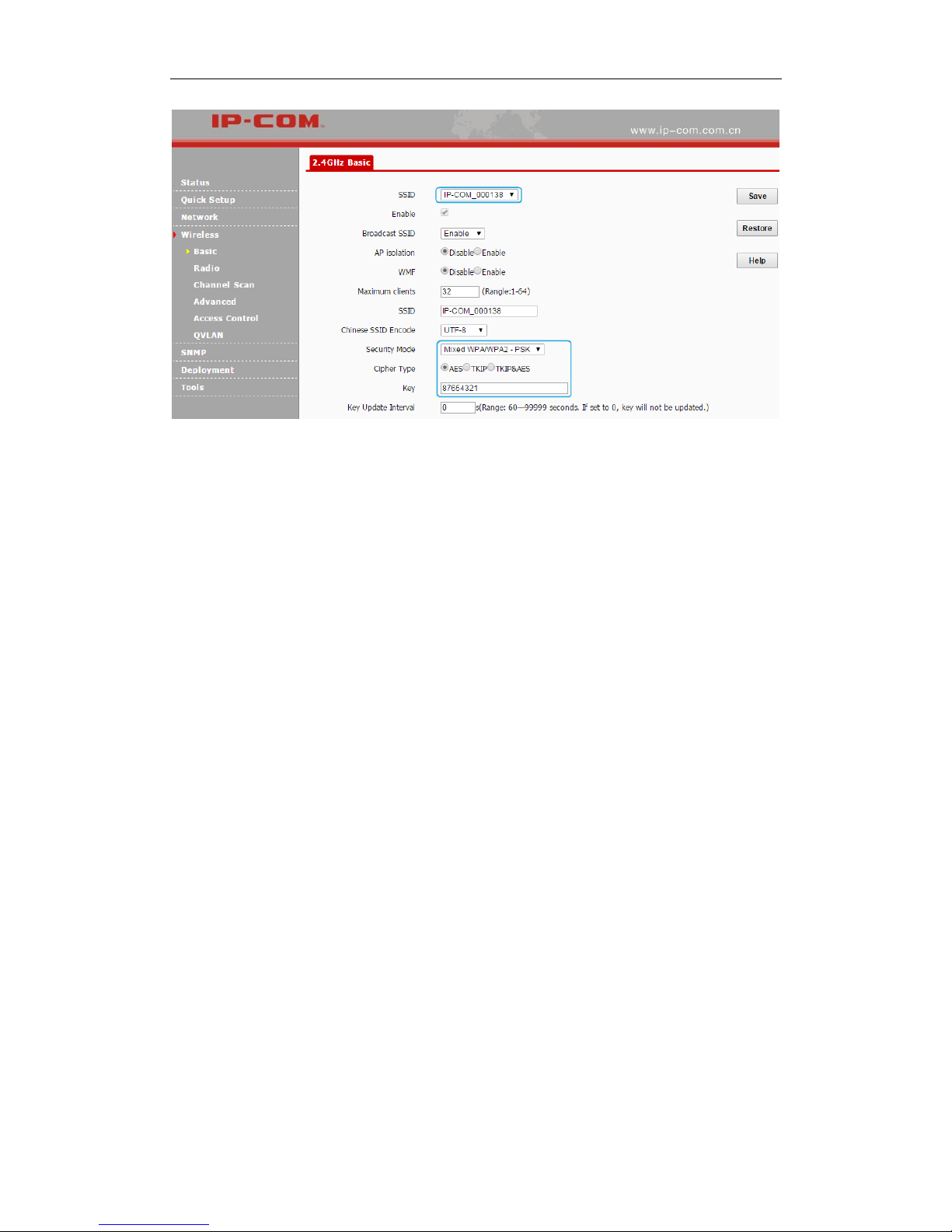
Configuration Steps for WPA-PSK, WPA2-PSK and Mixed WPA/WPA2-PSK: (In the
example, the cipher type is AES and its key is 87654321.)
❶ Select the SSID you wish to encrypt, say IP-COM_000138.
❷ Select the security mode, say Mixed WPA/WPA2-PSK.
❸ Select AES as its cipher type.
❹ Enter its key: 87654321.
❺ Click Save to apply your changes.
Page 33
28
3 More Features
Parameters for WPA-PSK, WPA2-PSK and Mixed WPA/WPA2-PSK are illustrated below:
Security Mode: Select the security mode: WPA-PSK, WPA2-PSK or Mixed
WPA/WPA2-PSK.
WPA-PSK: Support AES and TKIP.
WPA2-PSK: Support AES, TKIP and TKIP&AES.
Mixed WPA/WPA2-PSK: This is the mixed mode compliant with both WPA-PSK and
WPA2-PSK.
Cipher Type: Select the cipher type. WPA-PSK: AES and TKIP. WPA2-PSK and Mixed
WPA/WPA2-PSK: AES, TKIP and TKIP&AES.
AES: Advanced Encryption Standard. If selected, wireless speed can reach up to 300Mbps.
TKIP: Temporal Key Integrity Protocol. If selected, wireless speed can reach up to 54Mbps.
TKIP&AES: If selected, both AES and TKIP enabled wireless clients can join your wireless
network.
Key: Specify the security key you wish to configure (8~63 ASCII characters or 8~64 HEX
characters).
Key Update Interval: Configure the key update interval for encrypting WPA data.
Theoretically, the shorter the key update interval is, the more secure the WPA data will be. It
is advisable to leave the default value unchanged.
Page 34

29
3 More Features
WPA, WPA2
The WPA protocol implements the majority of the IEEE 802.11i standard. It enhances data
encryption through the Temporal Key Integrity Protocol (TKIP) which is a 128-bit per-packet key,
meaning that it dynamically generates a new key for each packet. WPA also includes a message
integrity check feature to prevent data packets from being hampered with. Only authorized
network users can access the wireless network. The later WPA2 protocol features compliance with
the full IEEE 802.11i standard and uses Advanced Encryption Standard (AES) in addition to TKIP
encryption protocol to guarantee better security than that provided by WEP or WPA.
Configuration Steps for WPA, WPA2: (In the example, the RADIUS server is 192.168.0.88, the
RADIUS port is 1812, the RADIUS password is 12345678, and the cipher type is AES)
❶ Select the SSID you wish to encrypt, say IP-COM_002070.
❷ Select WPA or WPA2 as its security mode.
❸ RADIUS Server: Enter 192.168.0.88.
❹ RADIUS Port: Enter 1812.
❺ RADIUS Password: Enter 12345678.
❻ Select AES as its cipher type.
❼ Click Save to apply your changes.
Page 35

30
3 More Features
Parameters for WPA, WPA2 are illustrated below:
Security Mode: Select the security mode, WPA or WPA2.
WPA: Support AES and TKIP.
WPA2: Support AES, TKIP and TKIP&AES.
RADIUS Server: The IP address of the RADIUS server for authentication in the LAN.
RADIUS Port: Port for RADIUS authentication.
RADIUS Password: Password for accessing the RADIUS server.
Cipher Type: Support AES, TKIP and TKIP&AES.
AES: Advanced Encryption Standard. If selected, wireless speed can reach up to 300Mbps.
TKIP: Temporal Key Integrity Protocol. If selected, wireless speed can reach up to 54Mbps.
TKIP&AES: If selected, both AES and TKIP enabled wireless clients can join your wireless
network.
Key Update Interval: Configure the key update interval for encrypting WPA data.
Theoretically, the shorter the key update interval is, the more secure the WPA data will be.
Page 36

31
3 More Features
Radio
Click Wireless > Radio to configure radio settings. In the AP Client mode and WDS mode, radio
settings are not configurable.
Parameters on this page are described below:
Enable Wireless: Check/Uncheck it to enable/disable WiFi function.
Country: Select the country where your device works to match channels in different regions.
Network Mode: Select a proper network mode for your device. The default mode is 11b/g/n
mixed. 11b: Select it if you have only 11b wireless devices in your wireless network. Up to
11Mbps wireless rate is supported in this mode. 11g: Select it if you have only 11g wireless
devices in your wireless network. Up to 54Mbps wireless rate is supported in this mode.
11b/g: Select it if you have 11b and 11g wireless devices in your wireless network. Up to
54Mbps wireless rate is supported in this mode. 11b/g/n mixed: Select it if you have 11b, 11g
and 11n wireless devices in your wireless network. Up to 300Mbps wireless rate is supported
in this mode.
Channel: Select a proper channel for your wireless network.
Channel Bandwidth: Select a proper channel bandwidth to enhance wireless performance.
This option is available only in 802.11b/g/n. Wireless speed in the channel bandwidth of
20/40 is 2 times in 20.
Extension Channel: This is used to ensure radio frequency for 802.11n devices on the
Page 37

32
3 More Features
network. This option is available in 11b/g/n mixed mode with channel bandwidth of 20/40.
Channel Lockout: Once this option is enabled, you can’t modify the country, channel,
channel bandwidth and extension channel manually.
SSID Isolation: Configure the AP’s different SSIDs’ isolation status. Once disabled, clients
connect to different SSIDs can’t communicate with each other. This will enhance your
network security. Once enabled, clients connect to different SSIDs can communicate with
each other.
WMM Capable: WMM is QoS for your wireless network. Enabling this option may ensure
better online stream wireless multimedia data such as video or audio (recommended).
APSD Capable: Automatic power save delivery. This function will be activated only when
WMM Capable is enabled. It is advisable to keep the default value unchanged.
Ageing Time: When the client connects to the AP successfully, and if there’s no data
transmission between the client and the AP within the set ageing time, the client will be
disconnected. If there’s data transmission within the set ageing time, the ageing time stops.
Channel Scan
Click Wireless > Channel Scan to enter page below:
Click Enable Scan to view wireless signals nearby. And then you can select a channel which is
the least used by neighboring networks (i.e. the channel with least interference) for your device for
better network performance.
Page 38

33
3 More Features
Advanced
Click Wireless > Advanced to configure advanced wireless settings.
Note:
If you are new to networking and have never configured these settings before, we recommend you
to leave the default settings unchanged.
Parameters on this page are described below:
Beacon Interval: This is a time interval between any two consecutive Beacon packets sent
by an Access Point to synchronize a wireless network. Specify a valid value between 20 and
999. The default setting is 100. Generally, the smaller the value is, the faster the client will
connect to the AP; the larger the value is, the faster the wireless data will be transmitted. It is
advisable to leave the default value unchanged.
Fragment Threshold: Specify a valid Fragment Threshold value between 256 and 2346. The
default is 2346. Any wireless packet exceeding the preset value will be divided into several
Page 39

34
3 More Features
fragments before transmission. When the error rate is relatively high, you can lower the
fragment threshold. In this way, if transmission failure occurs, only packets that are not sent
successfully needs re-sending, which will improve the transmission throughput. With no
interference, you can improve the fragment threshold to reduce times to acknowledge frames,
also improving the transmission throughput.
RTS Threshold: Specify a valid value between 1 and 2347. The default is 2347. If a packet
exceeds the preset value, RTS/CTS scheme will be used to reduce collisions. Set it to a
smaller value provided that there are distant clients and interference. If the RTS threshold
value is relatively small, the wireless access point uses the Carrier Sense Multiple Access
with Collision Detection (CSMA/CD) mechanism, and the data frame is transmitted
immediately after the silence period. The faster the frame is sent, the faster the wireless
network will recover from collisions. As the collision detection mechanism will occupy some
bandwidths, when the packet size is less than the RTS threshold, it is not advisable to enable
this mechanism.
DTIM Interval: A DTIM (Delivery Traffic Indication Message) Interval is a countdown
informing clients of the next window for listening to broadcast and multicast messages.
When such packets arrive in the router's buffer, the router will send DTIM (delivery traffic
indication message) and DTIM interval to alert clients of the receiving packets. Specify a
valid value between 1 and 255. The default is 1. Fox example, when the DTIM is 1, it means
that the AP will send all cached packets every other Beacon interval.
Receive Signal Strength: Configure signal strength for connected clients. When the wireless
client’s signal strength is lower than the setting value, the wireless client will not be allowed
to connect to the AP so that the wireless client can connect to a stronger WiFi.
TX Power: Configure wireless transmission power. You can change the value (8~18)
according to your actual network environment. The higher the TX power is, the wider the
AP’s WiFi coverage will be. However, reducing the TX power to some extent will be helpful
for your wireless performance and network security.
Power Lockout: Once this option is enabled, you can’t modify power manually.
Preamble: Mainly used for preamble synchronization. There are two types of preambles:
Page 40

35
3 More Features
long preamble and short preamble. The longer the preamble is, the shorter valid data will be.
The short preamble can help to enhance wireless transmission efficiency. For IEEE 802.1b,
the short preamble is optional. But for IEEE 802.11g, it is a must.
Signal Transmission: When coverage-oriented is selected, the AP’s WiFi coverage will be
wider. When you deploy many APs in your network, capacity-oriented option is
recommended.
Access Control
Click Wireless > Access Control to enter page below. This page allows you to specify a list of
devices to allow or disallow a connection to your wireless network via the device's MAC
addresses. To deactivate this feature, select "Disable"; to activate it, select "Allow" or "Deny". On
this page, you can also view wireless clients currently connected to the selected SSID so that you
can quickly add the MAC address you wish to configure access control settings.
Parameters on this page are described below:
SSID: Select the SSID you wish to configure access control settings.
MAC Filter Mode: Configure the MAC filter mode. Disable: Disable the Access Control
function. Allow: Only MAC addresses in the access control list are allowed to connect to the
SSID. Deny: Only MAC addresses in the access control list are not allowed to connect to the
SSID.
Page 41

36
3 More Features
To only deny the computer at the MAC address of the C8:9C:DC:12:13:13 to join your SSID
IP-COM_000138:
Configuration Steps:
❶ Select the SSID IP-COM_000138 and set the MAC filter mode to Deny.
❷ Enter C8:9C:DC:12:13:13 in the MAC Address field and click Add.
❸ Click Save to apply your changes.
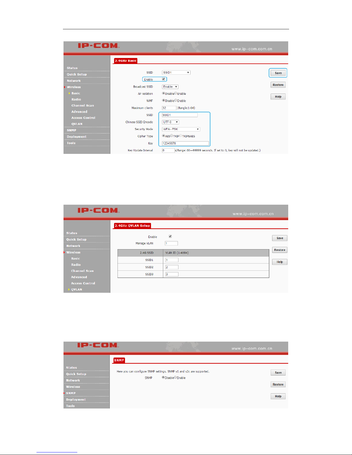
QVLAN
QVLAN enables this AP to broadcast up to 4 wireless networks with different names. When using
this feature, users could also assign different VLAN IDs to different wireless networks, which
makes it possible to get it work with switches which as VLAN assigned for different access levels
and authorities. Click Wireless > QVLAN to enter page below:
Page 42

37
3 More Features
Parameters on this page are illustrated below:
Enable: Check it to enable the QVLAN function. It is disabled by default. Once QVLAN is
enabled, to manage the AP wirelessly, you need to connect to the corresponding SSID of the
manage VLAN.
Manage VLAN: 802.1Q manage VLAN ID of the AP. The default value is 1. Once the
manage VLAN is changed, you need to re-connect to the new manage VLAN to manage the
AP.
2.4G SSID: Display SSIDs which have been enabled on the AP.
VLAN ID: Configure the corresponding SSID’s VLAN ID. It is 1000 by default. You can
specify a value between 1 and 4094.
Application Scenario:
People in a hotel are generally classified into three kinds: hotel executives, hotel staffs and
customers.
1. Hotel executives can access both the Internet and internal network in the hotel.
2. Hotel staffs can only have the access to internal network in the hotel,
3. Customers can only access the Internet. The network diagram is shown below:
Page 43

38
3 More Features
As shown in the network topology, AP515 should work with a switch that has VLAN assigned.
People in a hotel are generally classified into three kinds: hotel executives, hotel staffs and
customers. They belong to different VLAN networks to have different authorities (hotel
executives-VLAN1, hotel staffs-VLAN2 and customers-VLAN3).
Configuration Steps:
Configurations on the Switch (Configurations may vary on different switches):
Configure the port on the switch connected to the AP as the Trunk port, PVID=100 and all
VLANs allowed;
Configure the port on the switch connected to the server in the hotel as the Trunk port,
PVID=100 and VLAN1, VLAN2 allowed;
Configure the port on the switch connected to the router as the Trunk port, PVID=100 and
VLAN1, VLAN3 allowed.
Configurations on the AP:
❶ Click Wireless > Basic to enable 3 SSIDs: SSID1, SSID2 and SSID3, encrypt your SSIDs
and click Save.
Page 44
39
3 More Features
❷ Click Wireless > QVLAN and select the Enable option to enable the QVLAN function.
❸ Set SSID1 with VLAN ID 1, SSID2 with VLAN ID 2 and SSID3 with VLAN ID 3, and then
click Save to apply your changes.
SNMP
If you want to manage your AP via SNMP, click SNMP to enter page below:
Page 45

40
3 More Features
By default, SNMP is disabled. If you want to enable it, select Enable.
Parameters on this page are illustrated below:
SNMP: Disable/Enable the SNMP function. It is disabled by default.
Administrator Name: Administrator name of the AP. It is Administrator by default.
Device Name: Device name of the AP. The default name is AP515V1.0.
Location: Where the AP is located. The default is Shenzhen.
Read Community: Indicate the community string for read access to permit reading this AP’s
SNMP information. The default is public.
Read/Write Community: Indicate the community string for write/read access to permit
reading and writing this AP’s SNMP information. The default is private.
Deployment
This page allows you to manage APs via different deployment modes: local and cloud. Click
Deployment to enter page below:
Parameters on this page are illustrated below:
Deployment: Two deployment modes are supported. Local: When this option is selected, all
Page 46

41
3 More Features
current APs can only be managed by the local AC. Cloud: When this option is selected, all
current APs can only be managed by the cloud AC or a cloud server.
Device Name: This option is only available in Cloud mode. Note information of the AP.
Cloud AC Address: The WAN IP address or domain of the router that the cloud AC connects
to, such as www.ip-com.com.cn. This option is only available in Cloud deployment mode.
Cloud AC Manage Port: The port of the router that the cloud AC connects to and that is
used for managing APs (Range: 1024~65535). This option is only available in Cloud
deployment mode.
Cloud AC Upgrade Port: The port of the router that the cloud AC connects to and that is
used for upgrading APs (Range: 1024~65535). This option is only available in Cloud
deployment mode.
Network topology for local deployment:
Network topology for cloud deployment:
Page 47

42
3 More Features
Tools
The following nine parts are included in Tools section.
Maintenance: Upgrade the AP’s system software.
Time & Date: Configure system time and web idle timeout for the AP.
Logs: View and manage system logs of the AP.
Configuration: Backup and restore your configurations, and reset your AP to its factory defaults.
User Name & Password: Modify login username and password to prevent unauthorized accesses.
Diagnostics: Troubleshoot your AP to quickly find out where the problem is.
Reboot: Restart your AP.
LED: Turn on/off the LED of the AP.
Uplink Detection: Used for uplink detection.
Maintenance
If your device is in normal operation, it is not advisable to upgrade your device. If you want to
acquire the latest software version or better value-added functions for your device, you can access
our official website www.ip-com.com.cn to download the latest software for upgrading. Click
Tools > Maintenance to enter page below:
Page 48
43
3 More Features
Upgrading Steps:
❶ Launch a web browser and go to http://www.ip-com.com.cn to download the latest firmware.
❷ Direct to the Firmware Upgrade page.
❸ Click Choose File (in Google browser) to locate and select the upgrade file in the
corresponding directory on your hard disk.
❹ Click Upgrade.
When the upgrading completes, view the current firmware version to judge that whether you’ve
upgraded your AP successfully or not.
Note:
Do not disconnect power supply of the AP. If the power supply is interrupted, the upload may fail
and you need to re-upgrade it. If you are unable to log in to its web UI after cutting off its power
supply during the upgrading, cousult our technical stuff for assitance.
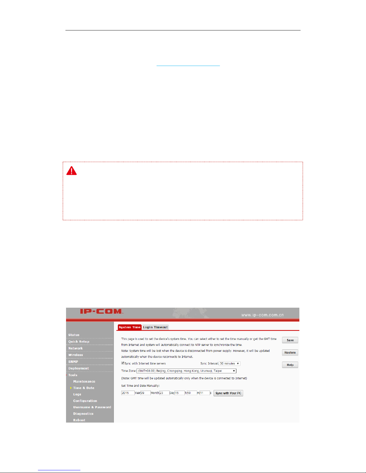
Time & Date
System Time
Click Tools > Time & Date > System Time to enter page below. This page is used to set the
device’s system time.
Page 49

44
3 More Features
System time can be configured using the following 2 methods:
Sync with Internet time servers
If enabled, system automatically connects to NTP server on the Internet to synchronize the time.
Configuration Steps:
❶ Check the Sync with Internet time servers box.
❷ Select the sync interval, say, 30 minutes.
❸ Select your time zone.
❹ Click Save to apply your changes.
Note:
To enable this function, please verify that your AP has connected to the Internet successfully.
Method: go to LAN Setup page to configure its IP info.
Set Time and Date Manually
Specify the time and date manually or click Sync with Your PC to automatically copy your
current PC's time to the device.
Configuration Steps:
❶ Uncheck the Sync with Internet time servers box.
Page 50

45
3 More Features
❷ Click Sync with your PC or enter the correct date and time in the input fields.
❸ Click Save to apply your changes.
Tip
Once power is not delivered on this device, the time settings will be lost. By default, Sync with
Internet time servers is enabled. When the device is able to access the Internet, it will
automatically connect to the NTP server on the Internet to synchronize the time.
Login Timeout
You are automatically logged out of the web UI after a period of inactivity. You can set the length
of the inactive period. The default login timeout is 5 minutes. To change the login timeout, click
Tools > Time & Date > Login Timeout to enter page below:
Page 51

46
3 More Features
Logs
The following two parts are included:
View Logs: View system logs since the latest reboot.
Log Setup: Configure log server and how many logs can be displayed on each page.
View Logs
Click Tools > Logs > View Logs to enter page below. Here you can view the history of the
device’s actions. Two types of logs are supported on this device: All and System. You can select
any one of them from the drop-down list. Click Refresh to update current log info or click Clear
to clear all logs.
Page 52

47
3 More Features
Note:
Rebooting your AP will clear all your system logs.
Configuring QVLAN settings, powering off your AP, backing up and restoring
configurations, resetting and upgrading your AP will reboot your AP.
To verify that the logs are correctly recorded, go to Tools > Time & Date to make your
system time correct.
Log Setup
Click Tools > Logs > Log Setup to configure system logs. Here you can set up the number of logs
and rules of log settings.
Page 53

48
3 More Features
Number of Logs
Up to 300 entries can be logged. The default is 150.
Log Server
If configured successfully, the system will begin to log events and simultaneously send them to the
specified log server in your LAN. You can view all logs there.
Configuration Steps:
❶ Click Add.
❷ Log Server IP: Specify the IP address of the syslog server in your LAN.
❸ Log Server Port: Specify the port of the syslog server in your LAN (If not allowed to
configure a port on your server, enter the default value 514).
❹ Check the Enable box to enable the log server.
❺ Click Save.
Page 54

49
3 More Features
❻ Check the "To use the following rules, you must check this box." Option to activate your
settings.
Tip
To make sure that system logs can be sent to the server successfully, you need to go to Network >
LAN Setup to set your AP’s IP address, subnet mask and gateway so that the route between the
AP and the log serve is reachable.
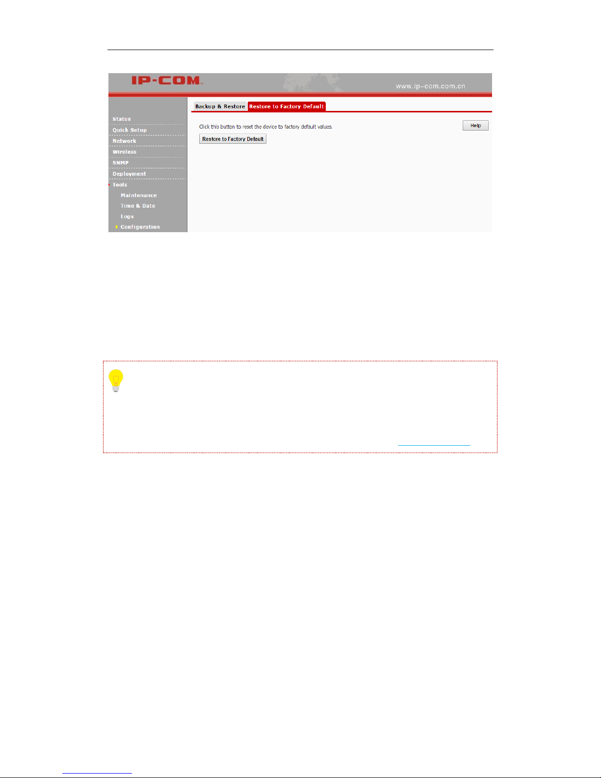
Configuration
The following two parts are included:
Backup & Restore: Backup current configurations to your local PC and restore previous
configurations to your AP.
Restore to Factory Default: Restore your AP to its factory defaults.
Backup & Restore
Click Tools > Configuration to enter page below:
Page 55

50
3 More Features
Backup
If you configure many settings on this device, which will make this device work in good status
and suitable environment, it’s suggested to backup settings for this device, which will be
convenient for troubleshooting and saving time for next time’s configuration.
Method: Click Backup and then follow onscreen prompts.
Restore
If you need to configure the same settings for multiple APs, or if your AP works improperly, you
can restore your AP to its previous configurations which you’ve backed up.
Method: Click Choose File (in Google browser) to download your previous configurations, click
Restore and then follow onscreen prompts.
Restore to Factory Default
If the device or client connected to the device fails to access the Internet due to incorrect
configurations and you cannot solve the problem, click Tools > Configuration > Restore to
Factory Default to reset the device and then reconfigure it.
Page 56
51
3 More Features
If you forgot the login info of the AP, like login IP address or login username, you can use the
RESET button to reset your AP.
❶ When the AP is powered on, press and hold the RESET button with something like a needle
for at least 7 seconds to reset your AP.
❷ Wait until the AP restarts.
Tip
After resetting your AP, the login IP address of the AP is 192.168.0.254, and the login username
and password are admin for both. For other default settings, see Appendix 2 Factory Defaults.
User Name & Password
Click Tools > User Name & Password to enter page below. Here you can change the user name
and password for web login. We suggest that you change this password to a more secure one.
Page 57

52
3 More Features
By default, two accounts are supported: administrator and user. The administrator can manage
your AP, while the user can only view the AP’s relevant information. Both the user name and
password for the administrator are admin. Both the user name and password for the user are user.
Diagnostics
This page allows you to test your network connection. If your network is malfunctioning, click
Tools > Diagnostics to use the ping utility to test your network and find out where the problem is.
Reboot
When some settings you have configured cannot be activated or your device is functioning
improperly, please reboot your device. The following two parts are included:
Page 58

53
3 More Features
Reboot: Reboot your AP manually.
Time Reboot: Reboot your AP at the specified time.
Reboot
Click Tools > Reboot to reboot your AP manually.
Tip
While rebooting your AP, all your WiFi connections will be disconnected. Thus, please reboot
your AP when the network is not busy.
Time Reboot
Click Tools > Reboot > Time Reboot to enter page below. Here you can reboot your device at the
specified time. Once this function is enabled, please make sure that your device is synchronized
with the Internet time server.
Page 59

54
3 More Features
Two methods for time reboot are available: As Interval and As Scheduled.
As Interval
The device will reboot automatically at intervals according to the interval you’ve configured.
❶ Check the Enable Auto Reboot Box.
❷ Select As Interval from the drop-down list.
❸ Specify the reboot interval (Recommended: 1440 minutes)
❹ Click Save to apply your changes.
Page 60

55
3 More Features
As Scheduled
The device will reboot regularly according to the time you’ve configured.
❶ Check the Enable Auto Reboot box.
❷ Select As Scheduled from the drop-down list.
❸ Check corresponding dates from Mon (Monday) to Sun (Sunday) to specify the reboot date.
❹ Specify the reboot time.
❺ Click Save to apply your changes.
LED
Click Tools > LED to turn off/on all LEDs.
Page 61
56
3 More Features
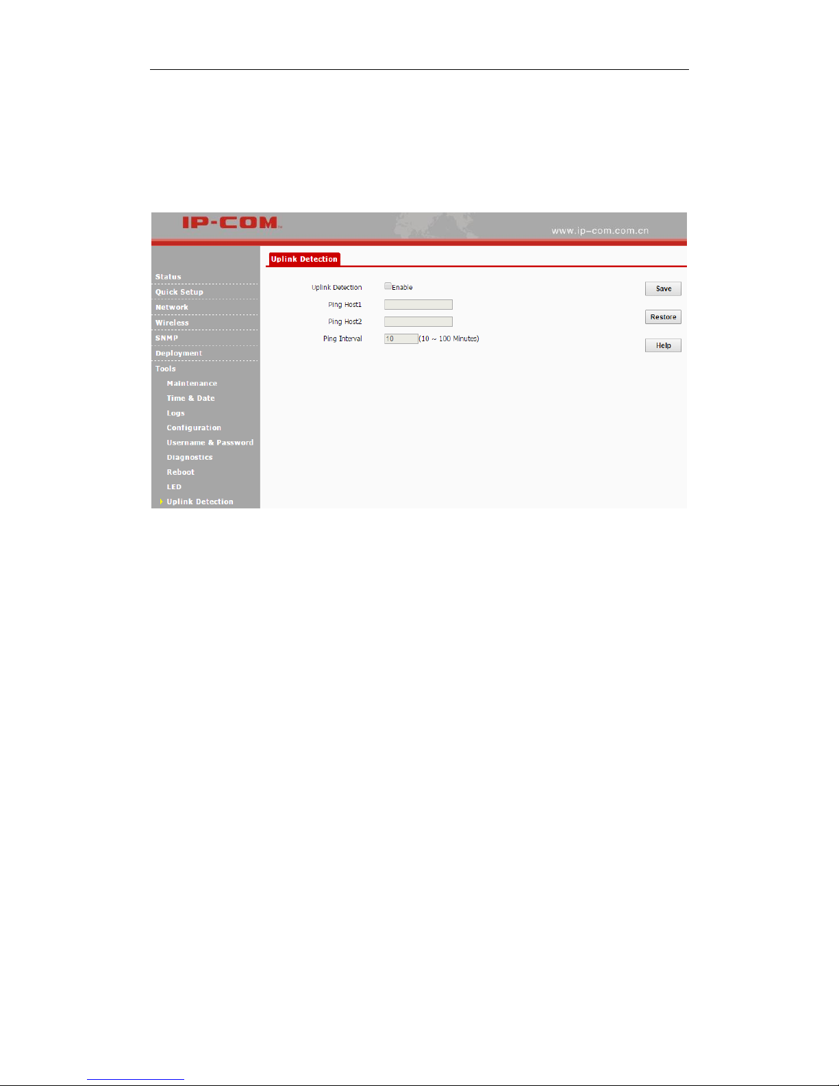
Uplink Detection
This function allows you to test the link between the AP and its uplink device. It is disabled by
default. Click Tools > Uplink Detection to enter page below:
Configuration Steps:
❶ Check the Enable box to enable the uplink detection function.
❷ Ping Host1/Host2: Enter the IP address of uplink device (s).
❸ Ping Interval: Specify the ping interval. Leave the default value unchanged if not necessary.
❹ Click Save.
When complete settings configured above, the AP will Ping the configured host within the set
Ping interval. If the configured host is unreachable, the WiFi feature of the AP will be disabled.
Page 62

57
Appendix
Appendix
1 Configure PC
Windows 8
❶ Right click the icon on the bottom right corner of your desktop.
❷ Click Open Network and Sharing Center.
❸ Click Ethernet > Properties.
Page 63

58
Appendix
❹ Find and double click Internet Protocol Version 4(TCP/IPv4).
❺ Select Use the following IP address, type in the IP address: 192.168.0.x (2~253), Subnet
mask: 255.255.255.0 and click OK.
❻ Click OK on the Ethernet Properties window.
Page 64

59
Appendix
Windows 7
❶ Click the icon on the bottom right corner of your desktop.
❷ Click Open Network and Sharing Center.
Tip
If you cannot find the icon on the bottom right corner of your desktop, follow steps below:
Click Start > Control Panel > Network and Internet > Network and Sharing Center.
❸ Click Local Area Connection > Properties.
Page 65

60
Appendix
❹ Find and double click Internet Protocol Version 4(TCP/IPv4).
❺ Select Use the following IP address, type in the IP address: 192.168.0.x (2~253), Subnet
mask: 255.255.255.0 and click OK.
❻ Click OK on the Local Area Connection Properties window.
Page 66
61
Appendix
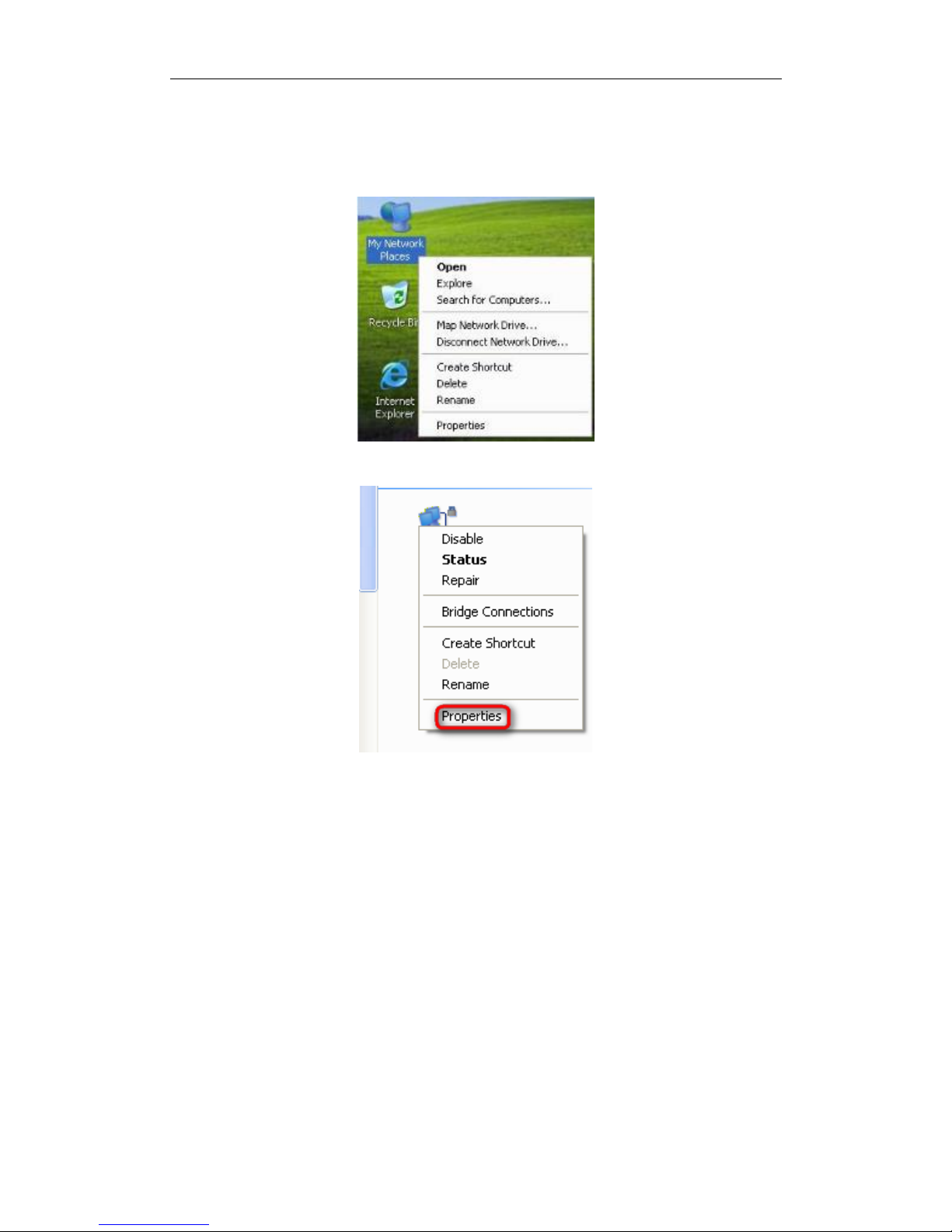
Windows XP
❶ Right click My Network Places on your desktop and select Properties.
❷ Right click Local Area Connection and select Properties.
❸ Scroll down to find and double click Internet Protocol (TCP/IP).
Page 67

62
Appendix
❹ Select Use the following IP address, type in the IP address: 192.168.0.x (2~253), Subnet
mask: 255.255.255.0 and click OK.
❺ Click OK on the Local Area Connection Properties window.
Page 68

63
Appendix
2 Factory Defaults
Parameter
Default Setting
Login
IP
192.168.0.254
User Name | Password
Administrator
admin|admin
Guest
user|user
LAN Setup
Address Mode
Static IP
IP Address (Management IP)
192.168.0.254
Subnet Mask
255.255.255.0
Gateway
192.168.0.1
Primary DNS Server
192.168.0.1
Device Name
AP515V1.0
DHCP Server
Disabled
SNMP
SNMP
Disabled
SNMP
Parameters
Administrator Name
Administrator
Device Name
AP515V1.0
Location
Shenzhen
Read Community
public
Read/Write Community
private
Tools
Time & Date
Sync with Internet Time
Servers
Enabled
Time Zone
(GMT+08:00) Beijing,
Chongqing, Hong Kong,
Urumqi, Taipei
WEB Login Timeout
5 minutes
Number of Logs
150
Time Reboot
Disabled
LED
Turn on all LED lights
Page 69

64
Appendix
3 FAQs
Q1: I enter the device’s LAN IP address in the web browser but cannot access this device’s
web UI. What should I do?
1) Verify that the IP address of computer should be a different one but on the same network
segment as the LAN IP address of this device. The default LAN IP address of AP is 192.168.0.254
and you need to set your PC to a static IP address within the following range: 192.168.0.X
(2~253);
2) Clear the browser cookies or try another web browser;
3) Close the firewall of your computer or try another computer;
If you are still unable to login, please restore the device to factory default settings and follow this
Install Guide to configure your settings again.
Q2: How do I restore my AP to its factory default settings?
Method 1: Via the RESET button
With the AP powered on, slide the bottom cover of the AP down to expose the RESET button,
press and hold it for over 7 seconds to restore the AP to its factory defaults. Note that once your
AP is reset, all your current settings will be lost and you need to reconfigure your AP.
Method 2: Via the Web UI
Log in to this device’s web UI, click Tools > Configuration > Restore to Factory Default to
reset the AP to its factory defaults.
Page 70

65
Appendix
4 Safety and Emission Statement
CE Mark Warning
This is a Class B product. In a domestic environment, this product may cause radio interference, in
which case the user may be required to take adequate measures. This device complies with EU
1999/5/EC.
NOTE: (1) The manufacturer is not responsible for any radio or TV interference caused by
unauthorized modifications to this equipment. (2) To avoid unnecessary radiation interference, it is
recommended to use a shielded RJ45 cable.
FCC Statement
This device complies with Part 15 of the FCC Rules. Operation is subject to the following two
conditions: (1) This device may not cause harmful interference, and (2) this device must accept
any interference received, including interference that may cause undesired operation.
This equipment has been tested and found to comply with the limits for a Class B digital device,
pursuant to Part 15 of the FCC Rules. These limits are designed to provide reasonable protection
against harmful interference in a residential installation. This equipment generates, uses and can
radiate radio frequency energy and, if not installed and used in accordance with the instructions,
may cause harmful interference to radio communications. However, there is no guarantee that
interference will not occur in a particular installation. If this equipment does cause harmful
interference to radio or television reception, which can be determined by turning the equipment off
and on, the user is encouraged to try to correct the interference by one of the following measures:
— Reorient or relocate the receiving antenna.
— Increase the separation between the equipment and receiver.
— Connect the equipment into an outlet on a circuit different from that to which the receiver is
connected.
Page 71

66
Appendix
— Consult the dealer or an experienced radio/TV technician for help.
FCC Caution: Any changes or modifications not expressly approved by the party responsible for
compliance could void the user's authority to operate this equipment.
This transmitter must not be co-located or operating in conjunction with any other antenna or
transmitter.
The manufacturer is not responsible for any radio or TV interference caused by unauthorized
modifications to this equipment.
Radiation Exposure Statement
This equipment complies with FCC radiation exposure limits set forth for an uncontrolled
environment. This equipment should be installed and operated with minimum distance 20cm
between the radiator & your body.
NOTE: (1) The manufacturer is not responsible for any radio or TV interference caused by
unauthorized modifications to this equipment. (2) To avoid unnecessary radiation interference, it is
recommended to use a shielded RJ45 cable.
 Loading...