

Page 1
Page 2

1
Network Setting
Network Setting ........................................................................................................................................................... 1
1 Network Setting ............................................................................................................................................................. 2
1.1 Interface Settings .................................................................................................................................................... 2
1.2 Interface and DHCP Server ................................................................................................................................... 14
1.3 Internet Settings ................................................................................................................................................... 25
1.4 NAT Rule ............................................................................................................................................................... 36
1.5 WAN Interface Settings ......................................................................................................................................... 47
1.6 Multi-WAN Policy ................................................................................................................................................. 49
2 IP Routing ..................................................................................................................................................................... 59
2.1 Overview............................................................................................................................................................... 59
2.2 Configuring IP Routing .......................................................................................................................................... 59
2.3 Example of IP Routing ........................................................................................................................................... 61
3 Example of Network Setting ........................................................................................................................................ 74
3.1 WAN Interface Is Not Created .............................................................................................................................. 74
3.2 WAN Interface Is Created ..................................................................................................................................... 93
Page 3

2
1 Network Setting
Network Setting includes: Interface Settings, Interface and DHCP Server, Internet Settings, NAT Rule,
WAN Interface Settings, and Multi-WAN Policy.
Note: If you want to configure NAT rules, WAN interface settings, and multi-WAN policies, create WAN
interfaces on the Interface Settings page first.
1.1 Interface Settings
1.1.1 Overview
AC3000-32 provides 4 physical ports. AC3000 and AC3000-64 provides 4 physical ports by default, and
you can add physical ports as required.
By default, all the physical ports are VLAN interfaces. You can change some of them to WAN interfaces.
A physical port can only be set to either a WAN interface or a VLAN interface.
ி VLAN Interface
It is used to connect to local users and APs. You can set a VLAN ID for each VLAN interface.
Note: Every VLAN interface of the AC has no PVID, no matter it has a VLAN ID or not. For a VLAN
interface, if VLAN ID=0, the VLAN interface can transmit and receive only data packets without tags. If
VLAN ID≠0, the VLAN interface can only transmit and receive data packets with the tag matching the
VLAN ID.
By default, fit APs have no management VLAN ID (VLAN ID=0), and the physical ports of fit APs
have no PVID. In distributed forwarding mode, when the AC delivers an SSID policy with a VLAN ID to
an AP, the management VLAN ID of the AP remains 0, but the PVID of the physical port of the AP is set
to 0. In centralized forwarding mode, when the AC delivers an SSID policy with a VLAN ID to an AP, no
management VLAN ID or PVID is assigned to the AP.
ி WAN Interface
It is used to connect to the internet. When you set a physical port as a WAN interface, you can configure
internet settings and NAT rules for the WAN interface to allow computers connected to the specified
VLAN interfaces to access the internet through the WAN interface.
Page 4

3
If you create WAN interfaces, the AC enables NAT function and functions as a gateway. The network
topology is as follows.
1.1.2 Configuring Interface Settings
By default, the AC provides a VLAN interface named "default". The VLAN interface contains all physical
ports of the AC and its VLAN ID is 0. See the following figure.
Creating a VLAN Interface
1. Log in to the web UI of the AC and choose Network Setting > Network Setting > Interface
Settings.
2. Click Add.
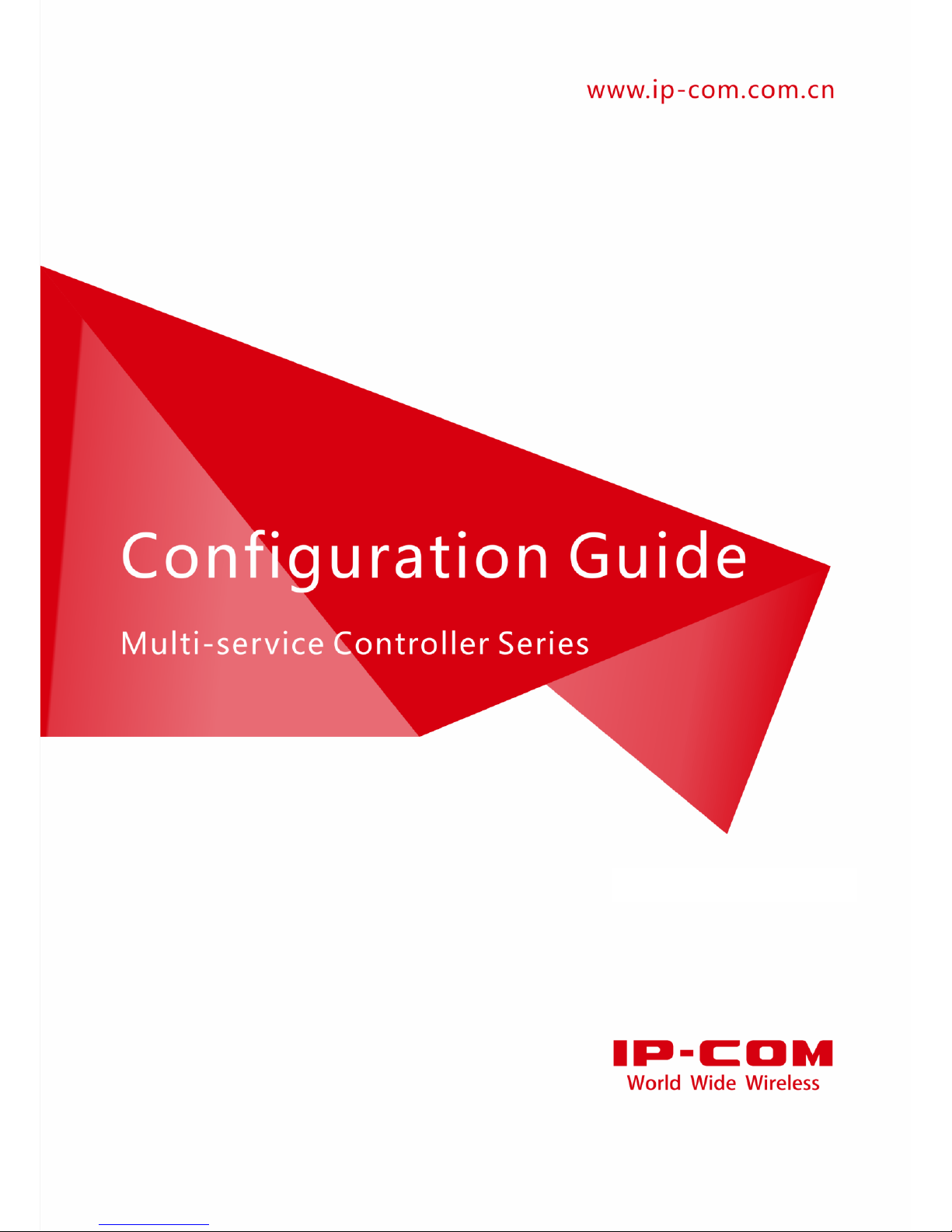
3. Configure the parameters in the window.
Interface Type: Select VLAN Interface.
Physical Port: Select one or more physical ports belonging to the VLAN Interface.
Interface Name: Set a unique name for the VLAN interface.
WAN Interface
VLAN
Interface
Core Switch
PoE Switch
User
User
Internet
Page 5
4
VLAN ID: Set a VLAN ID for the VLAN interface.
4. Click Save.
Parameter Description
Parameter
Description
Interface Type
Select an interface type for the configured rule.
VLAN Interface: It is used to connect to local computers or APs. The AC allows a maximum of 512
VLAN interfaces.
WAN Interface: It is used to connect to the internet.
Physical Port
Select the physical ports belonging to the VLAN interfaces.
A VLAN interface can include multiple physical ports. A physical port can belong to
multiple VLAN interfaces. One WAN interface matches only one physical port.
A physical port can be set only as either a VLAN interface or a WAN interface.
Interface
Name
Enter a unique name for the interface.
Only Chinese characters, letters, digits, underscores, and dashes are allowed. The interface name
cannot be blank. The range is 1 - 16 characters.
After you save the configured rule, the interface name cannot be changed.
VLAN ID
It is applicable to VLAN interfaces.
Set a VLAN ID for the configured VLAN interface. The range is 0 - 4094. “0” indicates that the VLAN
interface allows data packets that are not tagged to pass through. For more information, refer to VLAN
Interface.
Page 6
5
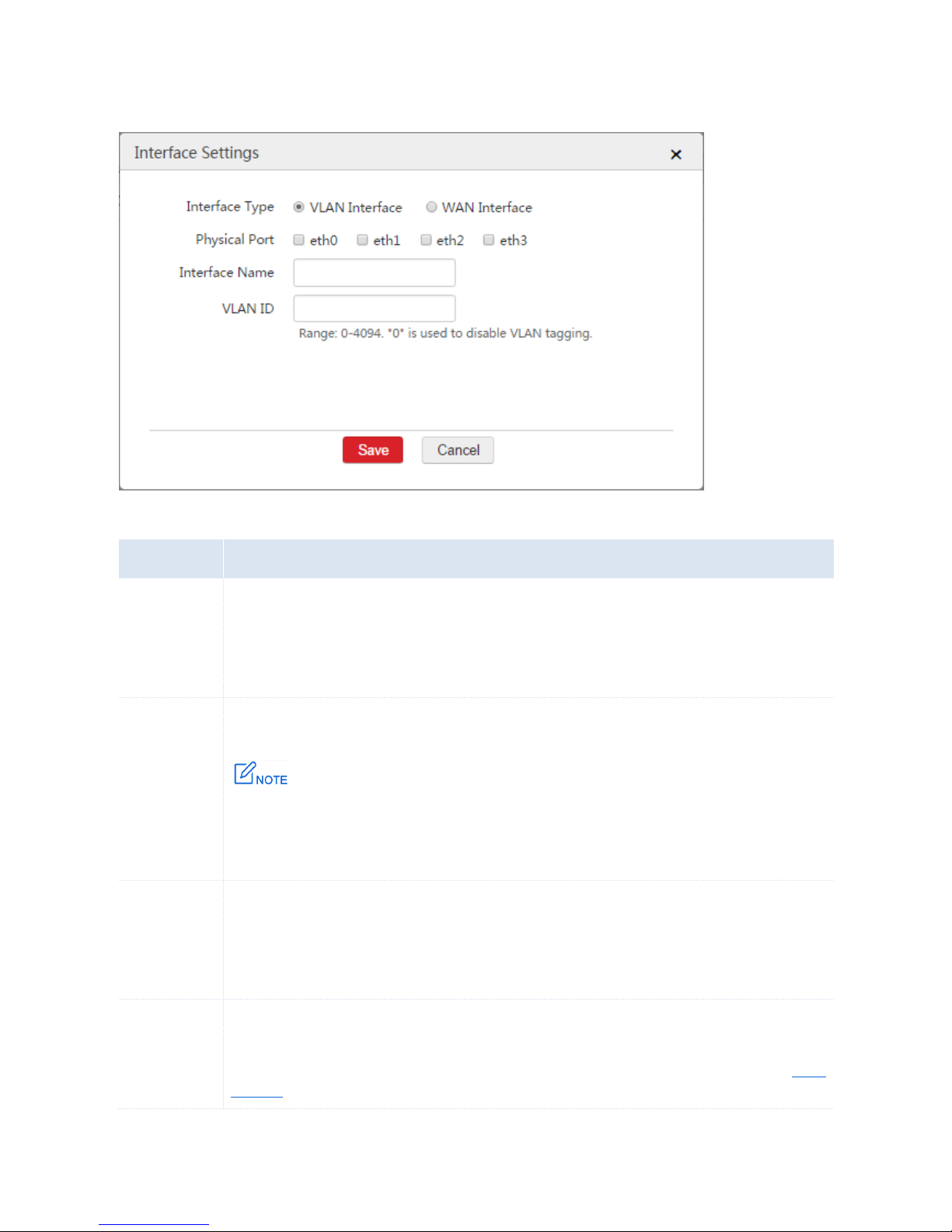
End: After you create a VLAN interface, you can choose Network Setting > Network Setting >
Interface Settings to view the VLAN interface. See the following figure.
Creating a WAN Interface
A WAN interface can contain only one physical port. A physical port configured as a VLAN interface
cannot be set as a WAN interface. If you want to create a WAN interface on a physical port, remove the
physical port from its VLAN interface first.
Procedure:
1. Log in to the web UI of the AC and go to Network Setting > Network Setting > Interface Settings.
2. Find the VLAN interface such as "default" and click .
3. Physical Port: Deselect the check box of the physical port, such as "eth3".
4. Click Save.
When the physical port is removed from the VLAN interface, you can set the physical port to a WAN
interface.
Page 7
6
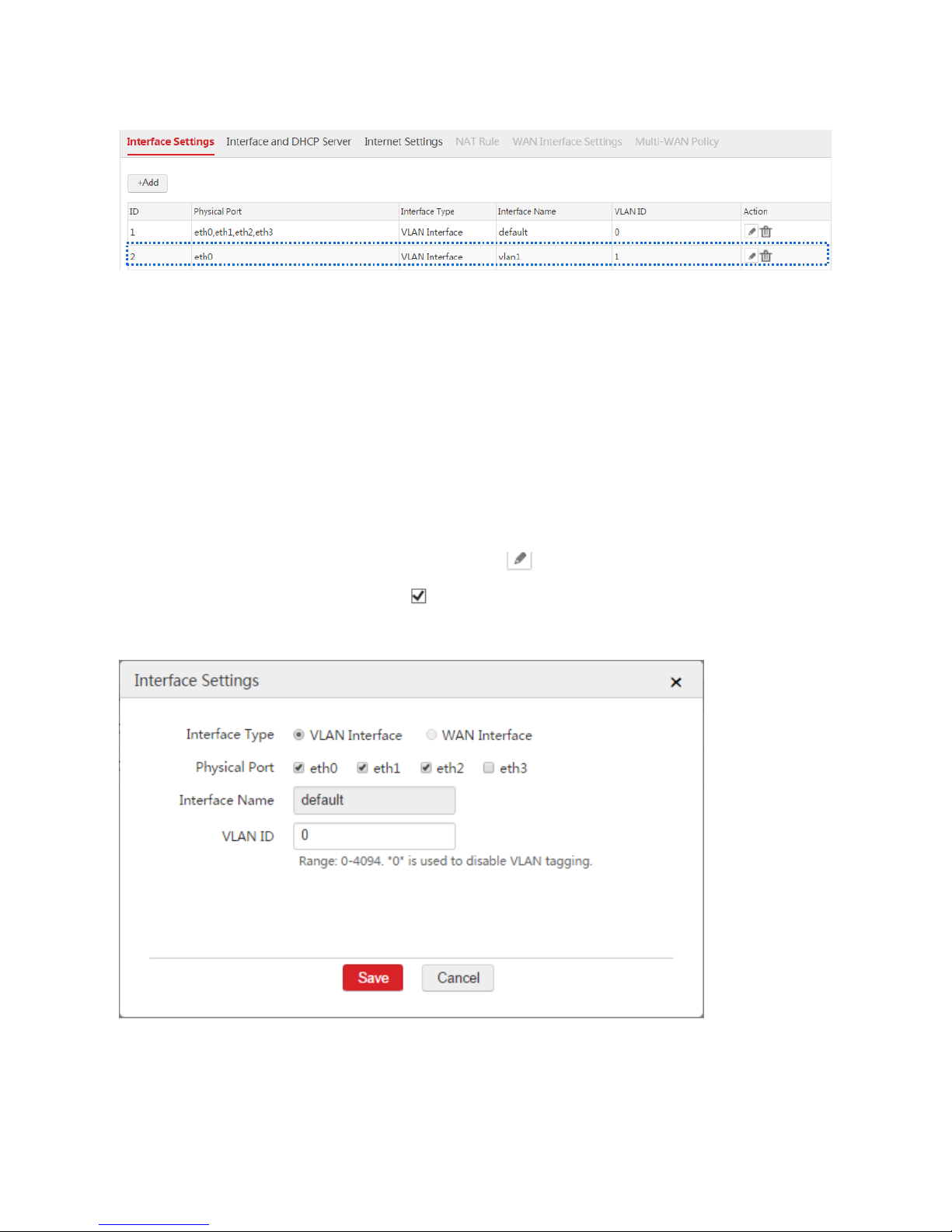
Procedure:
1. Choose Network Setting > Network Setting > Interface Settings and click Add.
2. Configure the parameters in the window.
Interface Type: Select WAN Interface.
Physical Port: Select the physical port such as "eth3".
Interface Name: Set a name such as "wan0".
3. Click Save.
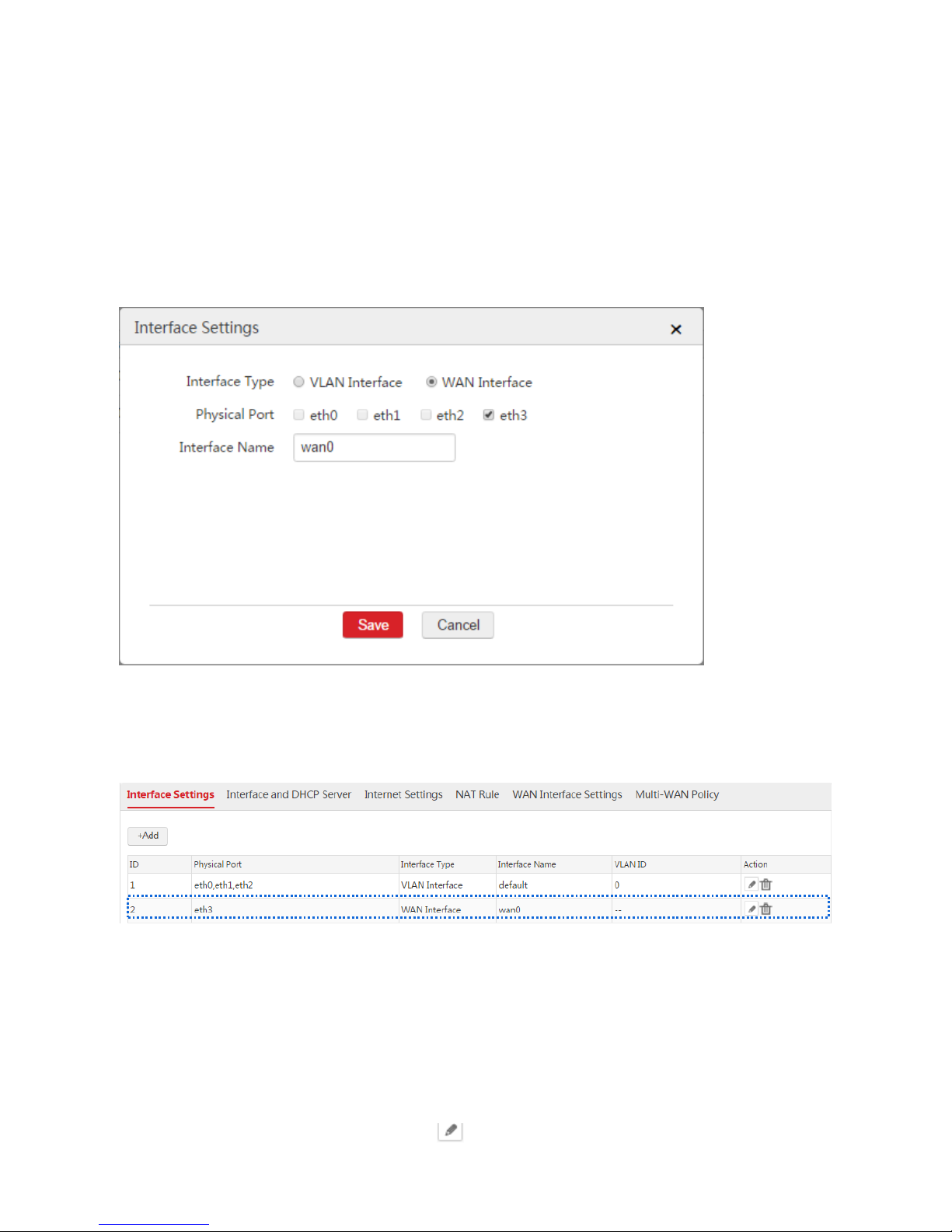
End: After you create a WAN interface, you can choose Network Setting > Network Setting >
Interface Settings to view the WAN interface. See the following figure. The eth3 port is set to a WAN
interface.
If you want to create more WAN interfaces, repeat the procedure. The AC supports creating a maximum
of N-1 WAN interfaces. N is the number of the physical ports of the AC.
Modifying an Interface
1. Choose Network Setting > Network Setting > Interface Settings.
2. Find the interface to be modified and click .
Page 8
7
3. Modify the parameters except Interface Name as required.
4. Click Save.
Deleting an Interface
When you delete an interface, all configurations of the interface are deleted, such as Interface and DHCP
Server, Internet Settings, and NAT Rule.
The default VLAN interface cannot be deleted.
Procedure:
1. Choose Network Setting > Network Setting > Interface Settings.
2. Click corresponding to the interface.
1.1.3 Example of VLAN Interface Application
Networking Requirement
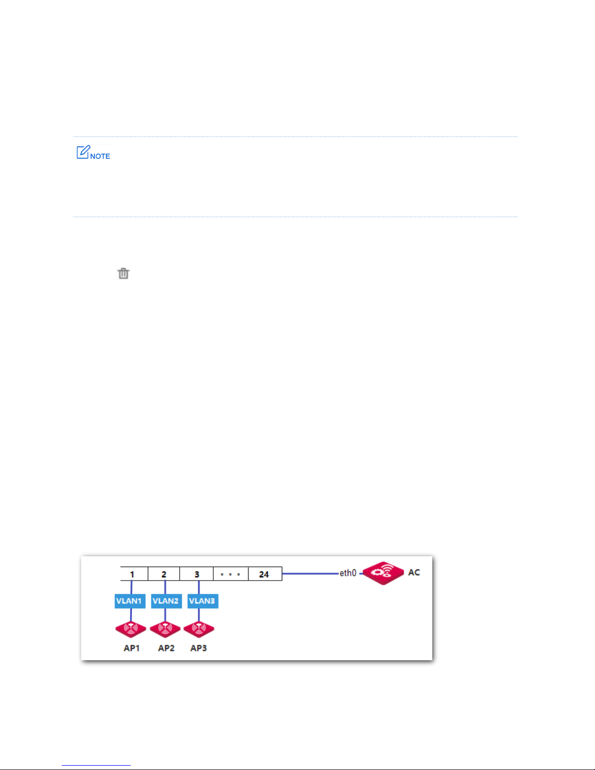
You need the AC to manage three APs on three different VLANs.
Assumption:
All the APs are restored to the factory settings.
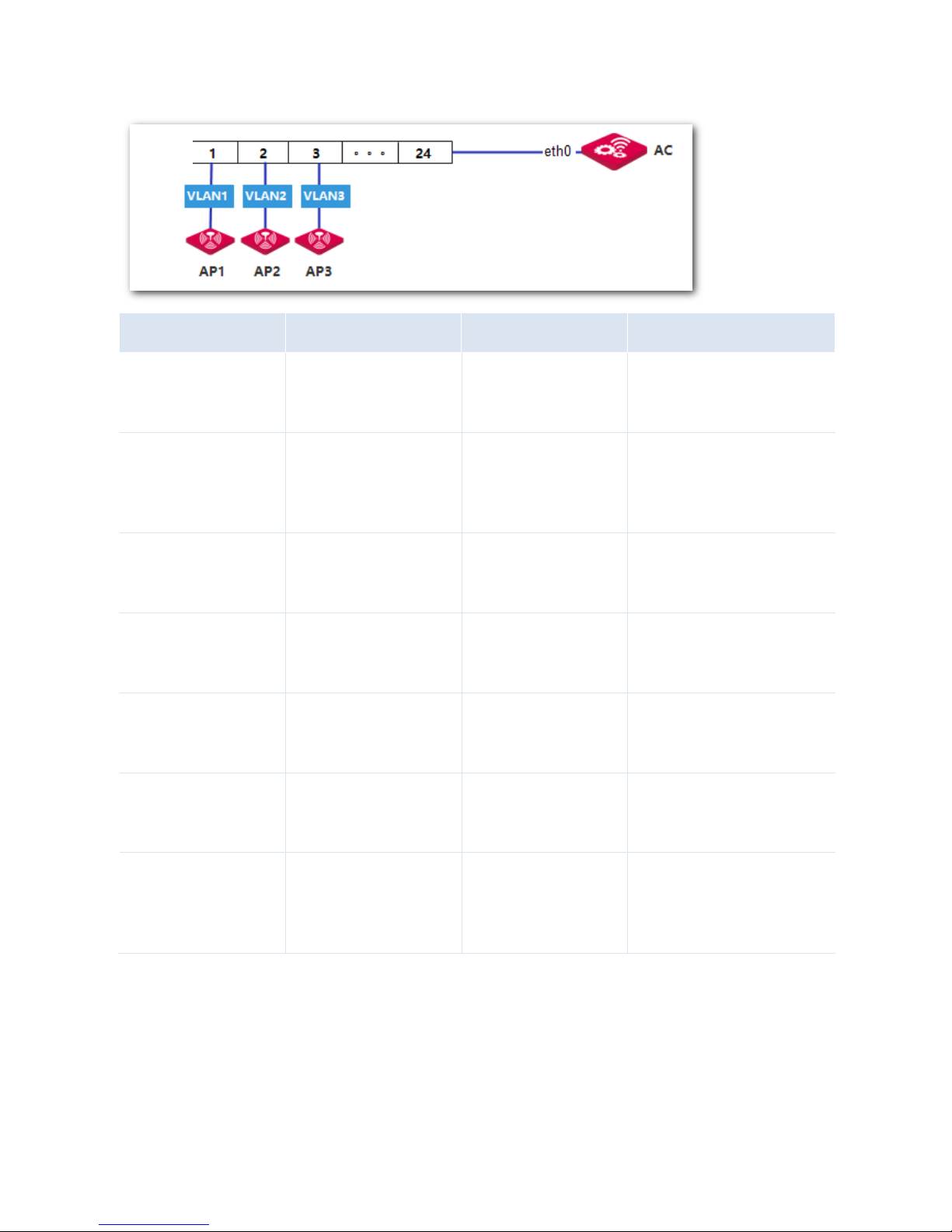
All the APs are connected to access ports of the switch, as shown in the following network
topology.
Network Topology
Switch
Page 9
8
Procedure
I. Configure the Switch
Configure the 802.1Q VLAN function on the switch. See the following table.
Switch Port
Connected to
VLAN ID
Port Type
PVID
1
AP1 1 Access
1 2 AP2 2 Access
2 3 AP3 3 Access
3
24
AC
1,2,3
Trunk
1
II. Configure the AC
According to the networking requirement, all the APs have no PVID or VLAN ID, and will obtain IP
addresses from the AC.
Procedure:
Step 1: Configure VLAN Interface
Choose Network Setting > Network Setting > Interface Settings, and configure three VLAN interfaces
used to communicate with the three APs.
1. Configure the VLAN interface used to communicate with AP1.
According to the networking requirement, the VLAN ID of the VLAN interface is 0, so you can use the
default VLAN interface.
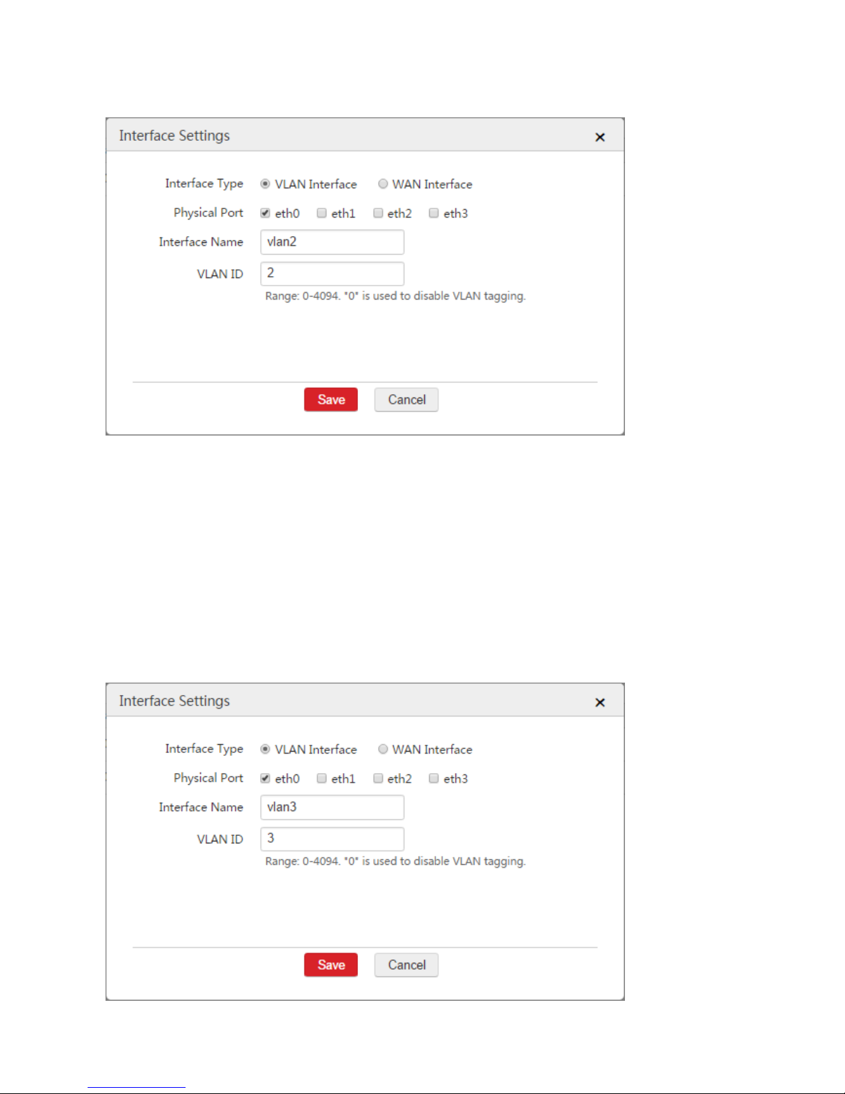
2. Configure the VLAN interface used to communicate with AP2.
1) Click Add.
2) Configure the parameters in the window.
Interface Type: Select "VLAN Interface".
Physical Port: Select the physical port connected to the switch, which is "eth0".
Interface Name: Set a name, such as "vlan2".
Page 10
9
VLAN ID: Enter the ID of the VLAN of AP2, which is "2".
3) Click Save.
3. Configure the VLAN interface used to communicate with AP3.
1) Click Add.
2) Configure the parameters in the window.
Interface Type: Select "VLAN Interface".
Physical Port: Select the physical port connected to the switch, which is "eth0".
Interface Name: Set a name, such as "vlan3".
VLAN ID: Enter the ID of the VLAN of AP2, which is "3".
3) Click Save.
Page 11

10
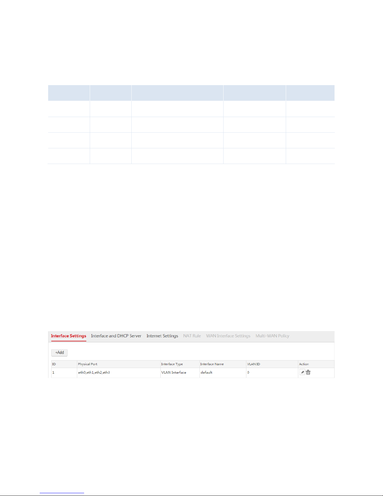
When you complete the step 1, the VLAN interface configurations are displayed. See the following figure.
Step 2: Configuring the Interfaces and DHCP Servers
On the Network Setting > Network Setting > Interface and DHCP Server page, configure three DHCP
servers on the created interfaces respectively. The DHCP servers are used to assign IP addresses to
AP1, AP2, and AP3.
1. Configure the DHCP server used to assign an IP address to AP1
According to step 1, AP1 uses the default VLAN interface to connect to the AC, so you can use the
default DHCP server to assign an IP address to AP1.
To Identify the DHCP server more easily, you can change the remark of the DHCP server to "AP1". See the
following figure.
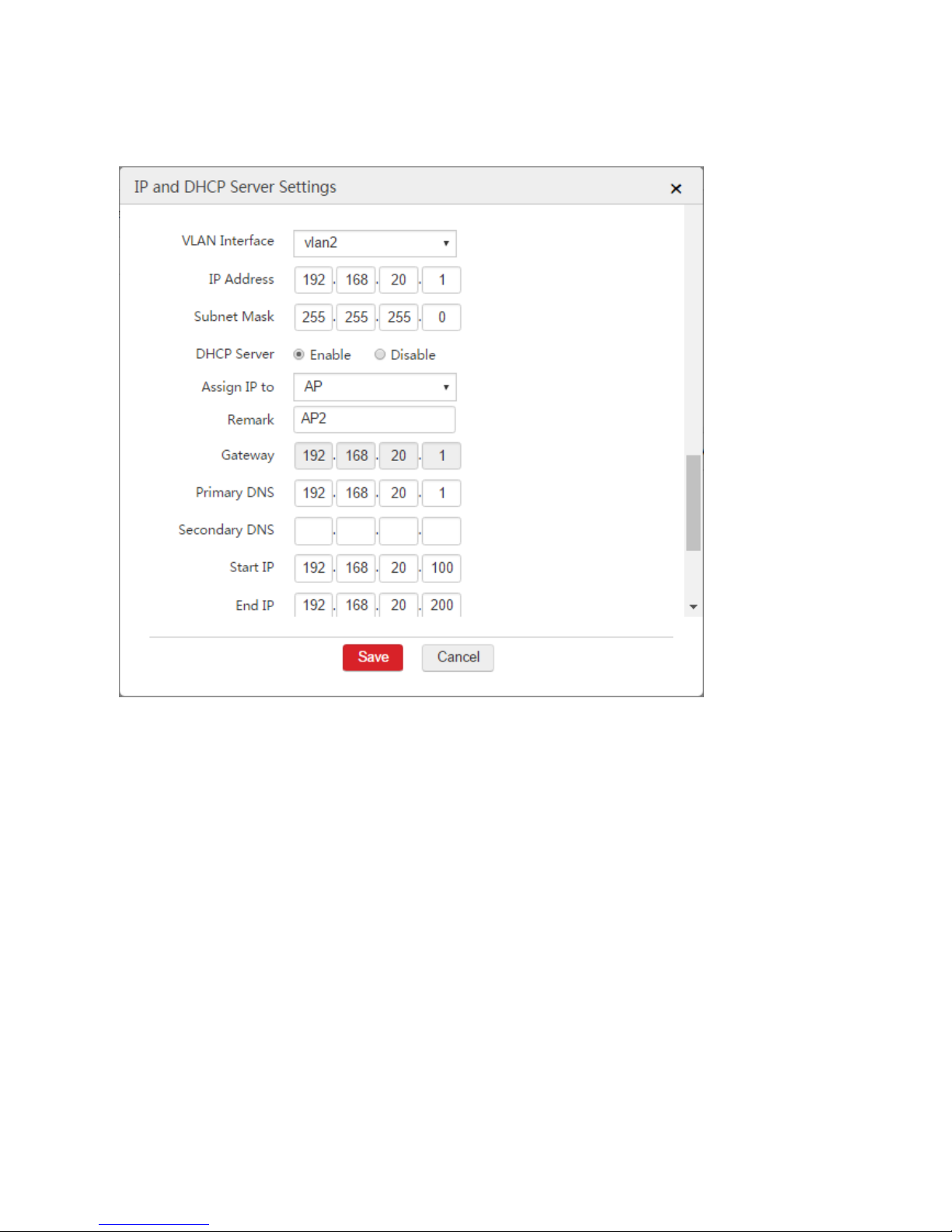
2. Configure the DHCP server used to assign IP address to AP2
1) Click Add.
2) Configure the parameters in the window.
VLAN Interface: Select "vlan2".
IP Address: Set an IP address for the VLAN interface, such as "192.168.20.1".
Subnet Mask: You can keep the default value.
DHCP Server: Select "Enable".
Remark: Set a name for the DHCP server, such as "AP2".
Primary DNS: In this example, you can set the primary DNS IP address "192.168.20.1" as the
DHCP server IP address.
Page 12
11
Start IP: Set the start IP address of the DHCP server pool, such as "192.168.20.100".
End IP: Set the end IP address of the DHCP server, such as "192.168.20.200".
3) Click Save.
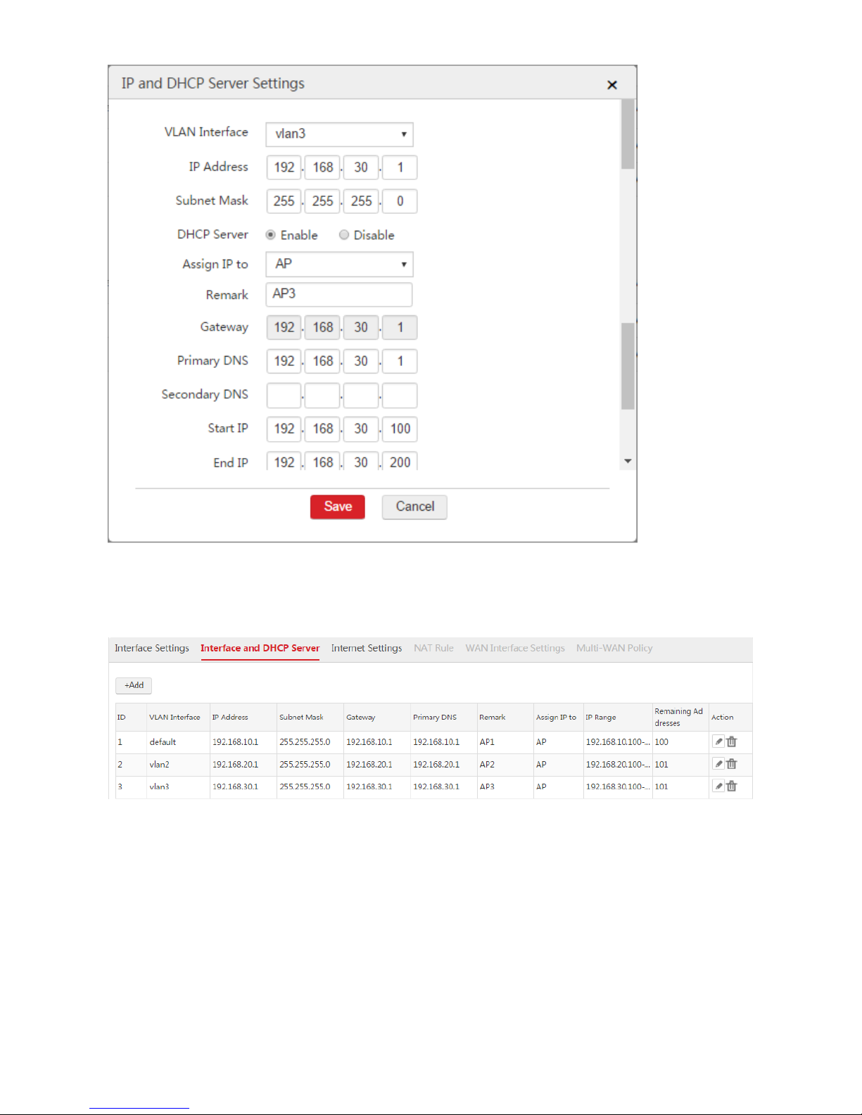
3. Configure the DHCP server used to assign IP address to AP3
1) Click Add.
2) Configure the parameters in the window.
VLAN Interface: Select "vlan3".
IP Address: Set an IP address for the VLAN interface, such as "192.168.30.1".
Subnet Mask: You can keep the default value.
DHCP Server: Select "Enable".
Remark: Set a name for the DHCP server, such as "AP3".
Primary DNS: In this example, you can set the primary DNS IP address as the DHCP server IP
address "192.168.30.1".
Start IP: Set the start IP address of the DHCP server pool, such as "192.168.30.100".
End IP: Set the end IP address of the DHCP server, such as "192.168.30.200".
3) Click Save.
Page 13
12
After the configuration is complete of the three DHCP servers is complete, you can view the information.
See the following figure.
Verification
After all the configurations are complete, AP1 obtains an IP address on the network segment of
192.168.10.0/24, AP2 obtains an IP address on the network segment of 192.168.20.0/24, and AP3
obtains an IP address on the network segment of 192.168.30.0/24. All the three APs are managed
successfully by the AC.
Page 14
13
Appendix: VLAN Process
Condition
Actions about AP1
Actions about AP2
Actions about AP3
When the switch’s access
port receives packets
from an AP, it will
Add tag: VLAN 1.
Add tag: VLAN 2.
Add tag: VLAN 3.
When the switch’s trunk
port transmits packets, it
will
Remove the tag and
forward the packets,
because VLAN
ID=PVID=1.
Keep the tag and forward
the packets, because
VLAN ID≠PVID.
Keep the tag and forward the
packets, because VLAN
ID≠PVID.
When the AC’s eth0 port
receives packets, the
packets’ status are
Untagged
With tag: VLAN ID 2
With tag: VLAN ID 3
The VLAN ID that the
eth0 port of the AC must
allow to pass through
VLAN ID 0
VLAN ID 2
VLAN ID 3
When the AC’s eth0 port
transmits packets, the
packets’ status are
Untagged
With tag: VLAN ID 2
With tag: VLAN ID 3
When the switch’s trunk
port receives packets
from the AC, it will
Add tag: VLAN 1. Because
it receives untagged
packets.
Keep tag and forward the
packets. Because it
receives tagged packets.
Keep tag and forward the
packets. Because it receives
tagged packets.
When the switch’s access
port transmits packets to
an AP, it will
Remove the tag and
forward the packets,
because VLAN
ID=PVID=1.
Remove the tag and
forward the packets,
because VLAN
ID=PVID=2.
Remove the tag and forward the
packets, because VLAN
ID=PVID=3.
Switch
Page 15
14
1.2 Interface and DHCP Server
1.2.1 Overview
The AC allows a maximum of 512 VLAN interfaces. On the Interface and DHCP Server page, you can
set IP addresses and DHCP servers for VLAN interfaces.
ி IP Address of VLAN Interface
Each IP address of a VLAN interface is a management IP address of the AC. You can use them to log in
to the web UI of the AC.
The IP address of a VLAN interface is also used to communicate with devices that are in the same VLAN
network with the interface. For example, a switch is connected to a VLAN interface of the AC and the IP
address of the switch is 192.168.0.1/24. To enable the AC and the switch communicate with each other,
you can set an IP address in the network segment 192.168.0.0/24 for the VLAN interface.
ி DHCP Server of VLAN Interface
You can enable the DHCP server of a VLAN interface to assign IP addresses, subnet mask, gateway,
and DNS address to APs or users connected to the VLAN interface.
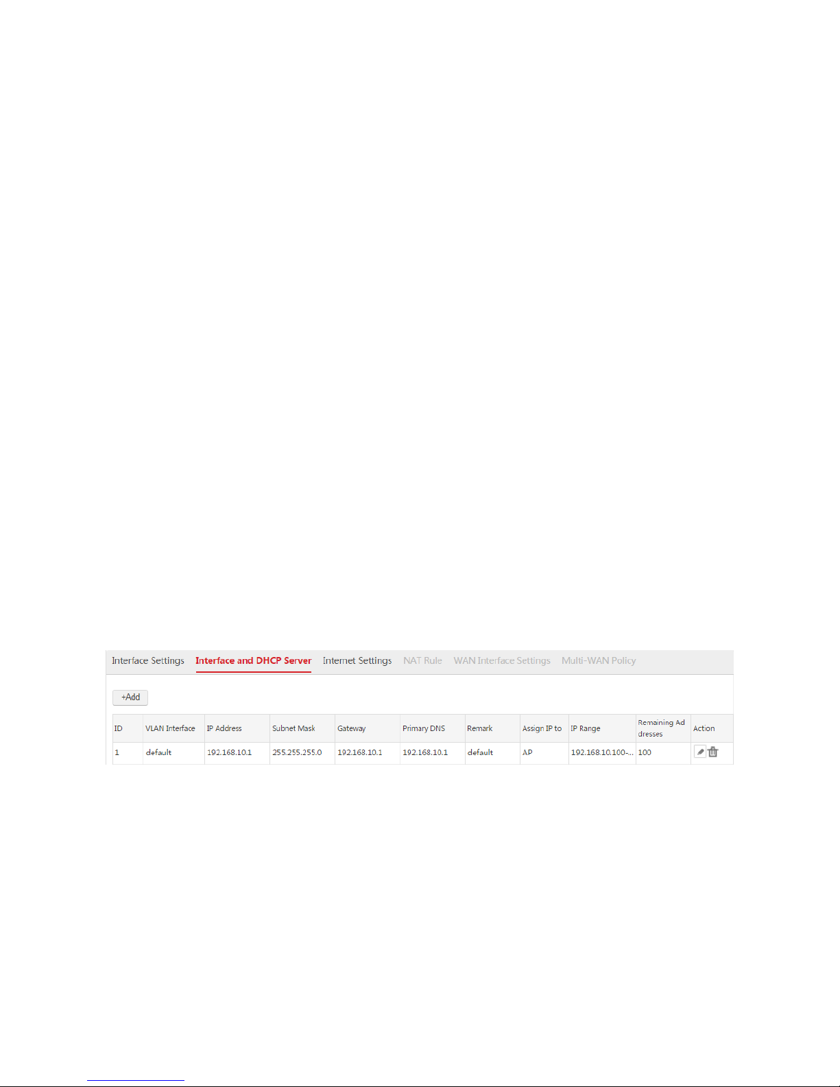
1.2.2 Configuring Interface and DHCP Server
The AC provides one default interface and DHCP server rule. See the following figure.
Creating an Interface and DHCP Server Rule
1. Log in to the web UI of the AC and go to Network Setting > Network Setting > Interface and
DHCP Server.
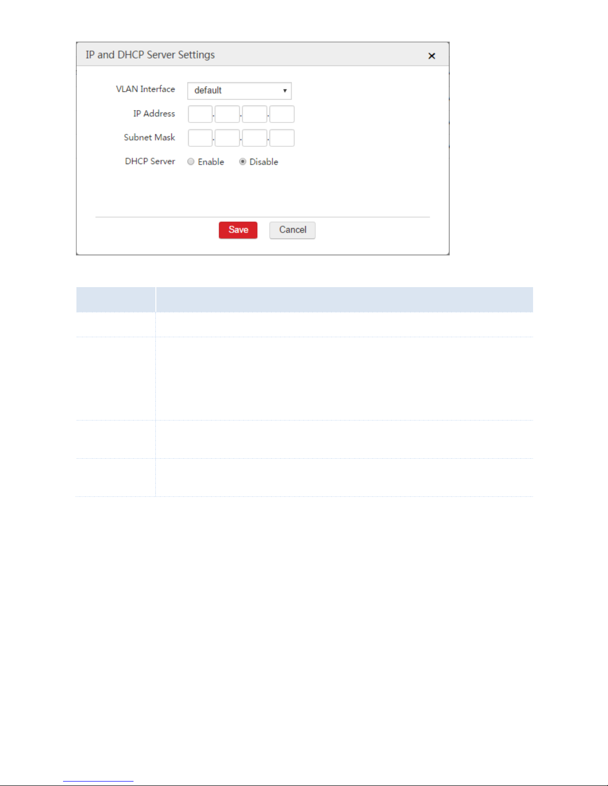
2. Click Add.
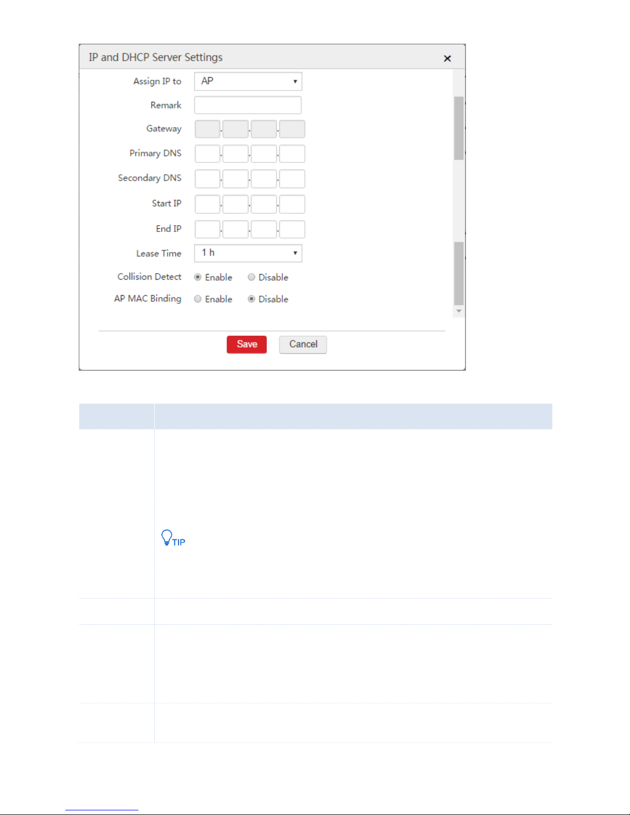
3. Configure the parameters in the window.
4. Click Save.
Page 16
15
Parameter Description
Parameter
Description
VLAN Interface
Select the VLAN interface to which the rule is to be applied.
IP Address
Set an IP address for the VLAN interface. The users belonging to the same VLAN network with the
interface can use the IP address to log in to the web UI of the AC to manage the AC.
The AC supports creating a maximum of 32 IP addresses for each VLAN interface. For each rule of
interface and DHCP server, you can enable the DHCP server to assign IP addresses to users or
APs, or disable the DHCP server.
Subnet Mask
Set the subnet mask for the VLAN interface. It is used to specify the network segment of the VLAN
interface.
DHCP Server
Enable or disable the DHCP server of the VLAN interface. If you enable the DHCP server, set the
following parameters. When you disable the DHCP server, skip the following parameters.
The DHCP server parameters are described as follows.
Page 17
16
Parameter Description
Parameter
Description
Assign IP to
Specify whether you want the DHCP server to assign IP addresses to users or APs.
AP: The DHCP server only assigns IP addresses to IP-COM fit APs.
User: The DHCP server only assigns IP addresses to users instead of IP-COM fit APs.
You are recommended to enable at lease one DHCP server for assigning IP addresses to APs.
Other DHCP servers on the network may also assign IP addresses to APs. If so, to make the AC
manage the APs, ensure that the route between the IP address of the VLAN interface and the
IP address of the APs are reachable.
Remark
Set a description for the DHCP server.
Gateway
Set the gateway IP address assigned to users or APs by the DHCP server.
If you already configure WAN interfaces and internet settings on the AC, you can set the gateway IP
address as the IP address of the VLAN interface to ensure the internet connectivity for users.
Otherwise, set the gateway as the LAN IP address of the upstream router.
Primary DNS
Set the primary DNS address assigned to users or APs by the DHCP server.
To ensure that users or APs can access the internet, the DNS address must be a correct DNS server
Page 18

17
Parameter
Description
address or a DNS proxy server address.
Do not set the DNS IP address as the IP address of the VLAN interface of the AC, because the
AC without WAN interface settings is not a DNS proxy.
Secondary DNS
(Optional) Set the secondary DNS address assigned to users or APs by the DHCP server. You can
keep this value blank.
Start IP
The start IP address of the IP address pool of the DHCP server.
End IP
The end IP address of the IP address pool of the DHCP server.
The start and end IP addresses must belong to the network segment of the IP address of the
VLAN interface.
Lease Time
Set the effective period of IP addresses assigned to DHCP clients (users or APs) by the DHCP
server.
When half of the lease time elapses, the DHCP client sends a DHCP request to the DHCP server to
extend the lease expiration time. If the request succeeds, the expiration time is extended. Otherwise,
the client sends the request again when 87.5% of the lease time elapses. If the second request
succeeds, the expiration time is extended. Otherwise, the client must request an IP address from the
DHCP server after the lease time expires.
When the expiration time elapses, if the client does not send a DHCP request, the DHCP server
releases the IP address.
Collision Detect
If the function is enabled, before assigning an IP address, the DHCP server checks whether the IP
address is in use.
If no, the DHCP server assigns the IP address to a DHCP client. If yes, the DHCP server checks the
availability of other IP addresses until finding an available IP address.
AP MAC Binding
Enabling this function can avoid ARP deception.
If this function is enabled, the AC only saves valid APs’ MAC addresses to its ARP table and drops
other MAC addresses. In this way, the AC avoids ARP deception and ensures proper communication
over the network.
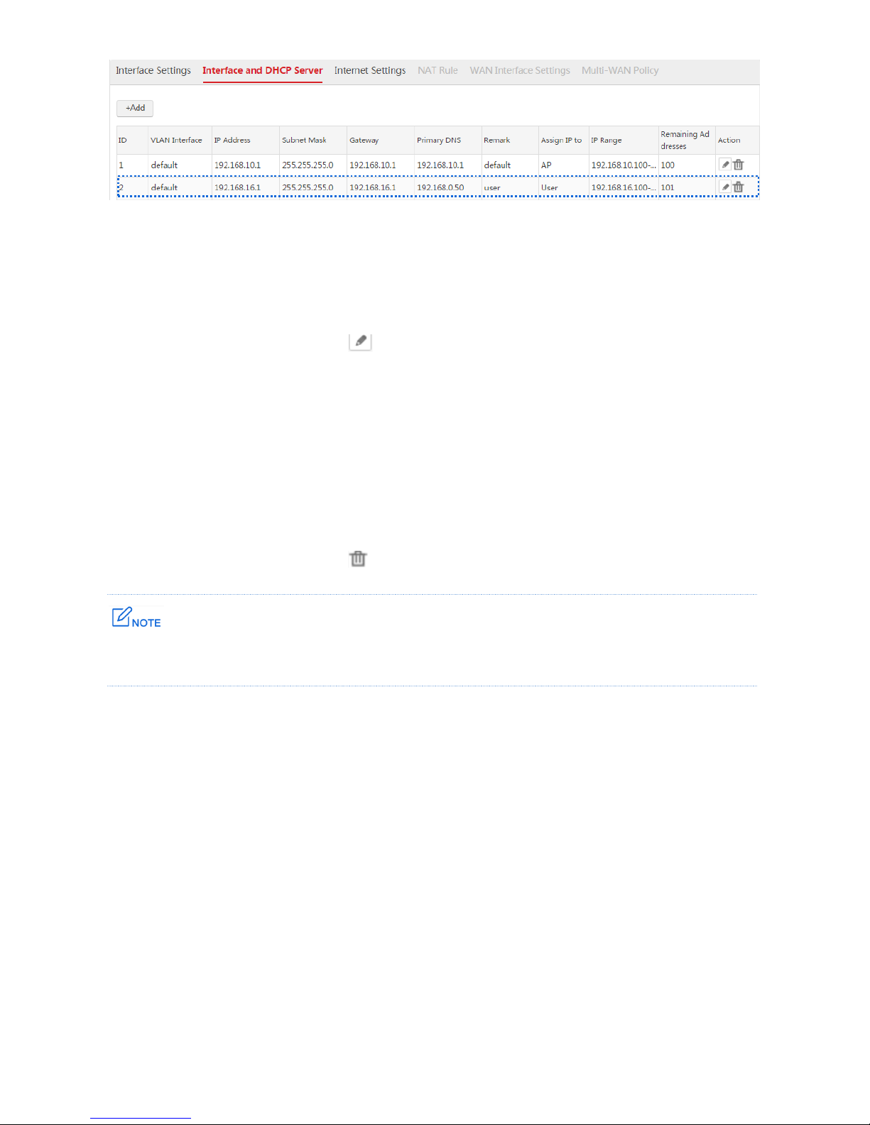
End: After the configuration is complete, you can choose Network Setting > Network Setting >
Interface and DHCP Server to view the information. See the following figure.
Page 19
18
Modifying an Interface and DHCP Server Rule
1. Log in to the web UI of the AC and go to Network Setting > Network Setting > Interface and
DHCP Server.
2. Find the item to be modified, click .
3. Modify the parameters, except "VLAN Interface", in the window.
4. Click Save.
Deleting an Interface and DHCP Server Rule
1. Log in to the web UI of the AC and go to Network Setting > Network Setting > Interface and
DHCP Server.
2. Find the item to be modified, click .
The default IP address can be deleted. If you delete the default IP address, use other IP addresses to manage
the AC.
Page 20
19
1.2.3 Example of Interface and DHCP Server
Networking Requirement
The AC has succeeded in managing the APs. The users connected to the APs need to obtain IP
addresses from the AC to access the internet.
Assumption:
Before the configuration, the APs have no management VLAN ID. The SSID policy of the APs
uses the centralized forwarding mode.
The LAN IP address of the router is 192.168.100.50.
The router is a DNS proxy server.
All users belong to VLAN 100.
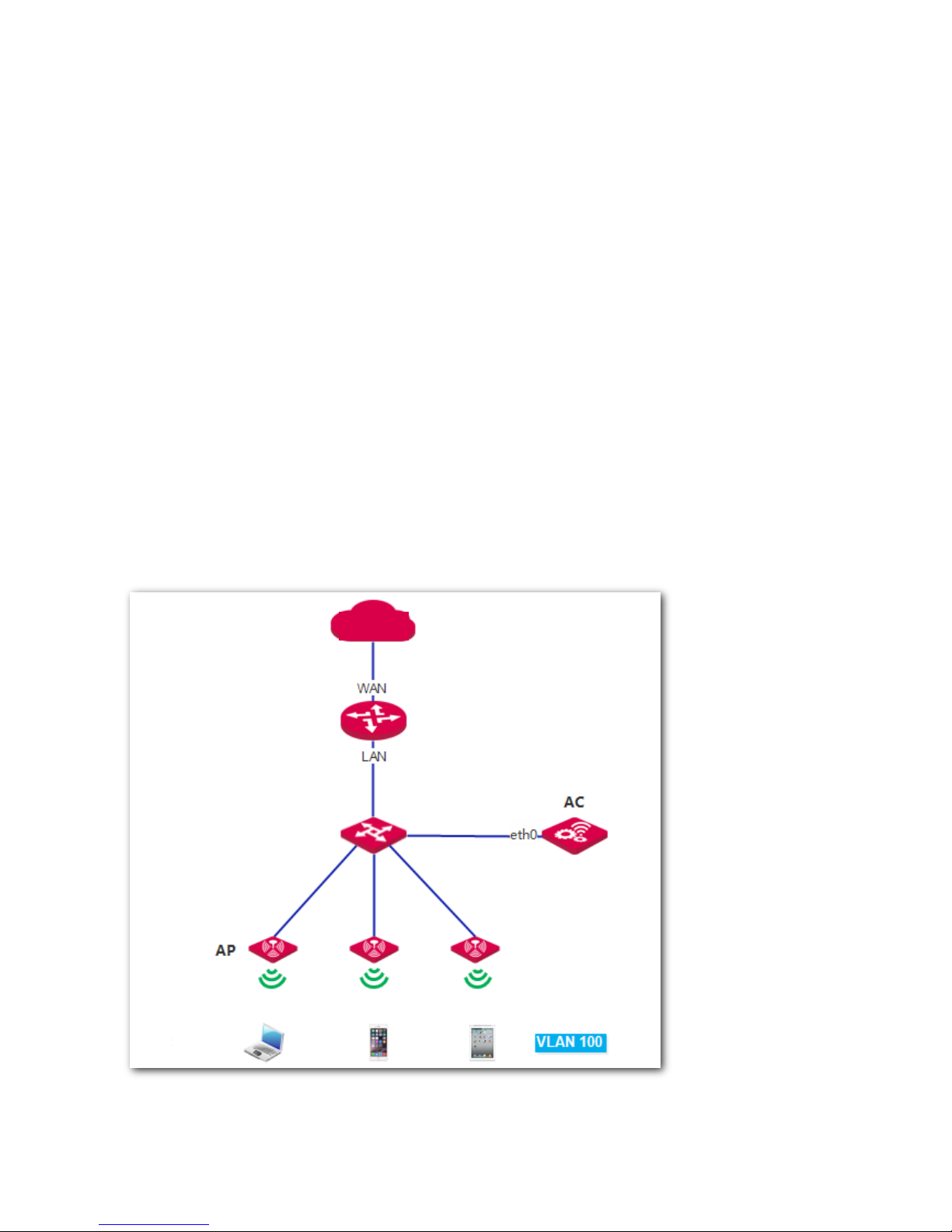
Network Topology
Internet
Router
Switch
User
Page 21

20
Procedure
I. Configure the Switch
In centralized forwarding mode, data of VLAN 100 from the users is encapsulated and invisible to the
switch. So there is no need to set the ports connected to the APs. The VLAN configuration of the other
ports of the switch is shown as follows.
The port connected to
VLAN ID
Port Type
PVID
AC
1,100
Trunk
1
Router
100
Access
100
II. Configure the AC to Deliver SSID Policy
Procedure:
Step 1: Create VLAN Interface
1. Log in to the web UI of the AC and go to Network Setting > Network Setting > Interface Settings.
2. Click Add.
3. Configure the parameters in the window.
Interface Type: Select "VLAN Interface".
Physical Port: Select the physical port connected to the switch, which is "eth0".
Interface Name: Set a name for the VLAN interface, such as "vlan100".
VLAN ID: Enter the VLAN ID of the users' VLAN network, which is "100".
4. Click Save.
Page 22

21
Step 2: Configure Interface and DHCP Server
1. Log in to the web UI of the AC and go to Network Setting > Network Setting > Interface and
DHCP Server.
2. Click Add.
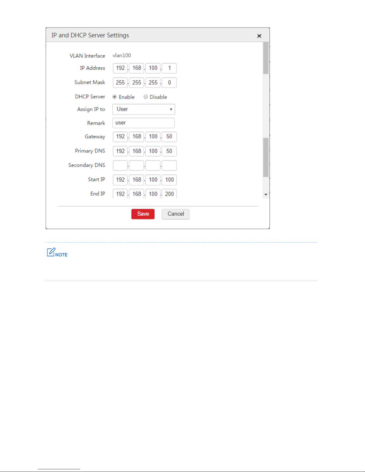
3. Configure the parameters in the window.
VLAN Interface: Select the configured VLAN interface from Step 1, which is "vlan100".
IP Address: Set an IP address for the VLAN interface, such as "192.168.100.1".
Subnet Mask: You can keep the default value.
DHCP Server: Select "Enable".
Assign IP to: Select "User".
Remark: Set a name for the DHCP server, such as "user".
Gateway: In this example, enter the LAN IP address of the router: 192.168.100.50.
Primary DNS: Set a correct DNS server address or a DNS proxy server address. In this example, it
is "192.168.100.50".
Start IP: Set a start IP address of the DHCP address pool, such as "192.168.100.100".
End IP: Set an end IP address of the DHCP address pool, such as "192.168.200.100".
4. Click Save.
Page 23
22
The gateway is the LAN IP address 192.168.100.50 of the router instead of the IP address of the VLAN
interface of the AC.
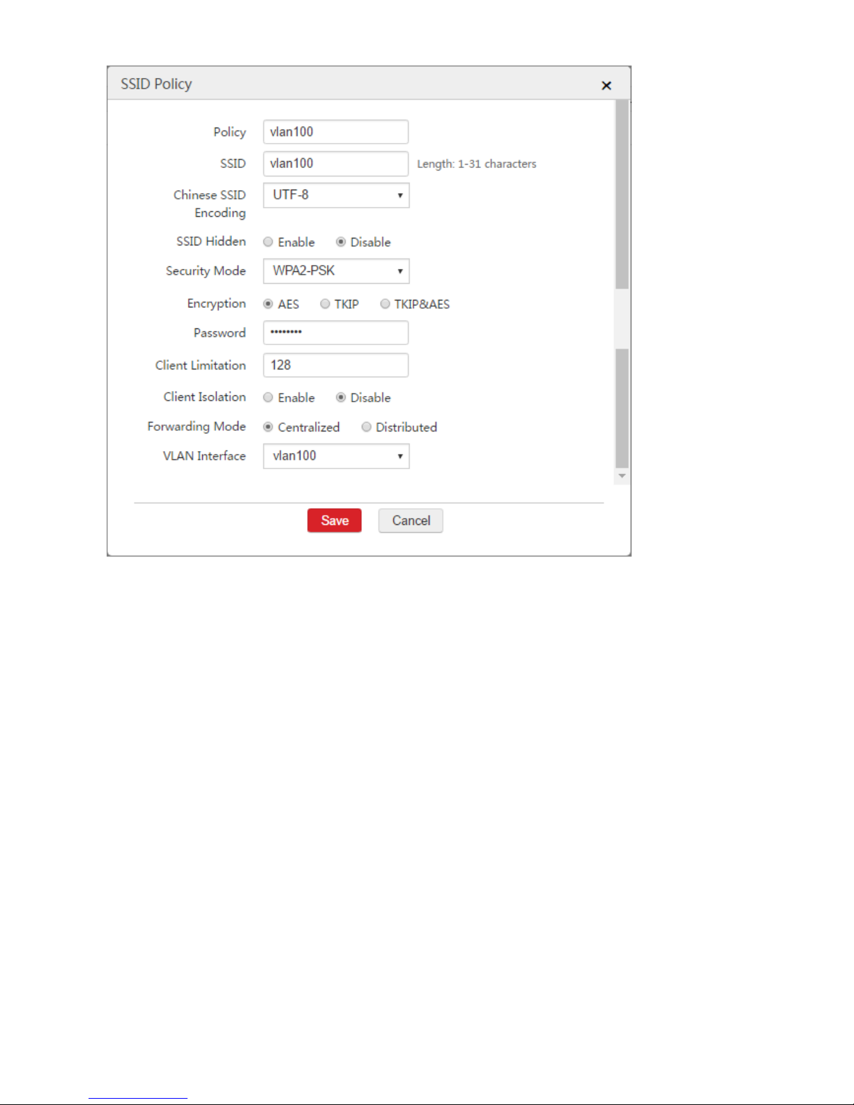
Step 3: Create SSID Policy
1. Choose Wireless Policy > SSID Policy > SSID Policy.
2. Click Add.
3. Configure the parameters in the window.
Policy: Set a name for the SSID policy, such as "vlan100".
SSID: Set a name for the wireless network, such as "vlan100".
Security Mode: Select a security mode for the wireless network, such as "WPA2-PSK".
Encryption: It is recommended to select "AES".
Password: Set a password for wireless network, such as "12345678".
Forwarding Mode: Select "Centralized".
VLAN Interface: Select the configured VLAN interface "vlan100".
4. Click Save.
Page 24
23
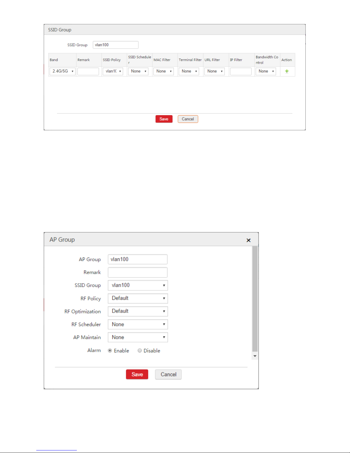
Step 4: Create SSID Group
1. Choose AP Management > SSID Group.
2. Click Add.
3. Configure the parameters in the window.
SSID Group: Set a name for the SSID group, such as "vlan100".
SSID Policy: Select the configured SSID policy from Step 3, which is "vlan100".
4. Click Save.
Page 25
24
Step 5: Create AP Group
1. Choose AP Management > AP Group.
2. Click Add.
3. Configure the parameters in the window.
AP Group: Set a name for the AP group, such as "vlan100".
SSID Group: Select the configured SSID group from Step 4, which is "vlan100".
4. Click Save.
Page 26
25
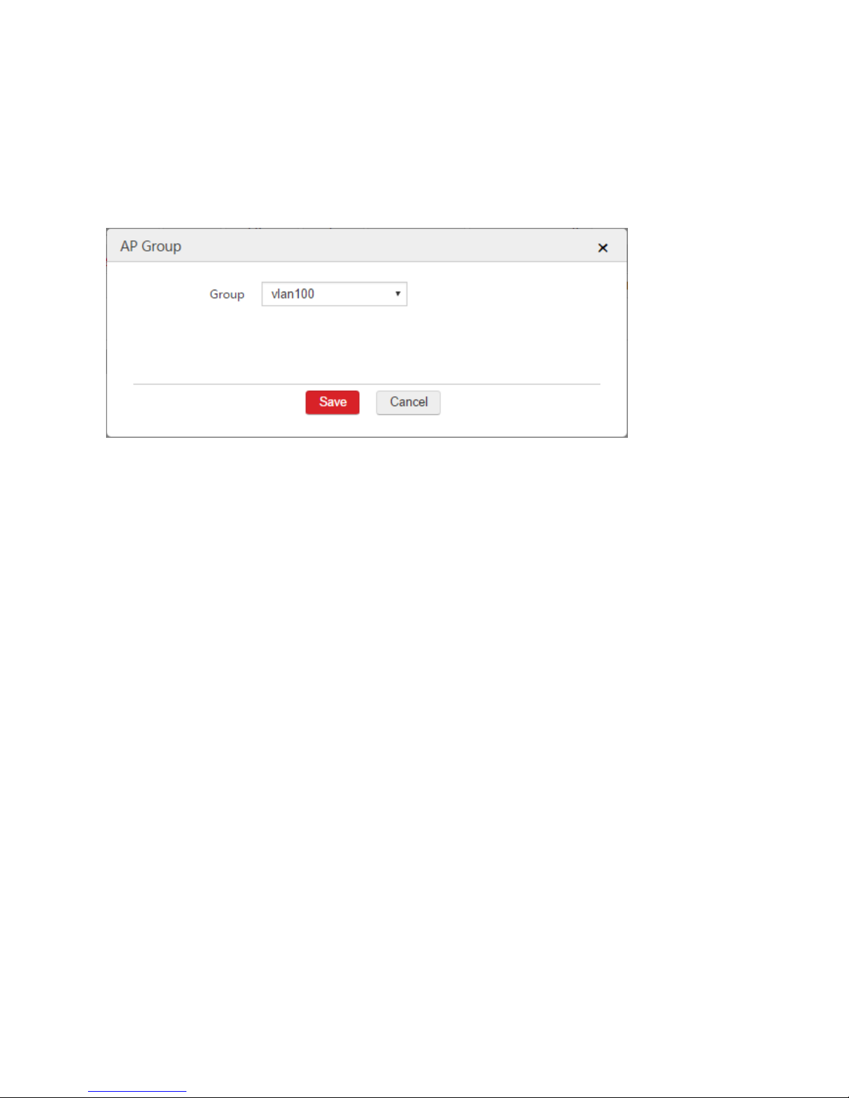
Step 6: Batch Group
1. Choose AP Management > Modify AP.
2. Select the APs that need the SSID policy and click "Batch Group".
3. Group: Select the configured AP group from Step 5, which is "vlan100".
4. Click Save.
After the configuration is complete, the AC delivers the settings of the AP group to the APs and the APs
reboot. Please wait 1 - 2 minutes for the APs to get online.
Verification
When users connect to the wireless network "vlan100", they can access the internet by obtaining IP
addresses on the network segment 192.168.100.0/24, and their gateway and DNS address are
192.168.100.50.
1.3 Internet Settings
1.3.1 Overview
Through this function, you can connect the AC to the internet. After the AC is connected to the internet, it
can:
Manage APs in the internet.
Synchronize the system time of the AC with the internet time to ensure that the time-related
functions of the AC work properly.
Page 27
26
1.3.2 Configuring Internet Settings
Whether you create WAN interfaces or not, you can configure internet settings for the AC. For how to
configure internet settings, refer to WAN Interface Is Not Created or WAN Interface Is Created.
WAN Interface Is Not Created
Before configuring the internet settings, go to Network Setting > Network Setting > Interface and DHCP
Server and create an IP address on the VLAN interface to communicate with the gateway configured in the
internet settings. For details, refer to Example of Internet Settings.
Configuring the Internet Settings
1. Choose Network Setting > Network Setting > Internet Settings.
2. Click Add.
3. Configure the parameters in the window.
4. Click Save.
Page 28
27
Parameter Description
Parameter
Description
Gateway
The default gateway of the AC. You must configure at lease one IP address of a VLAN interface to
belong to the network segment of the gateway so as to make the AC and the gateway communicate
with each other.
The gateway is generally the LAN IP address of the upstream router.
Primary DNS
The correct DNS server address or DNS proxy server address. If the upstream router is DNS proxy
server, you can set the primary DNS server as the LAN IP address of the router. Otherwise, contact
the ISP to obtain the correct DNS address.
Secondary DNS
The correct DNS server address or DNS proxy server address. It is optional.
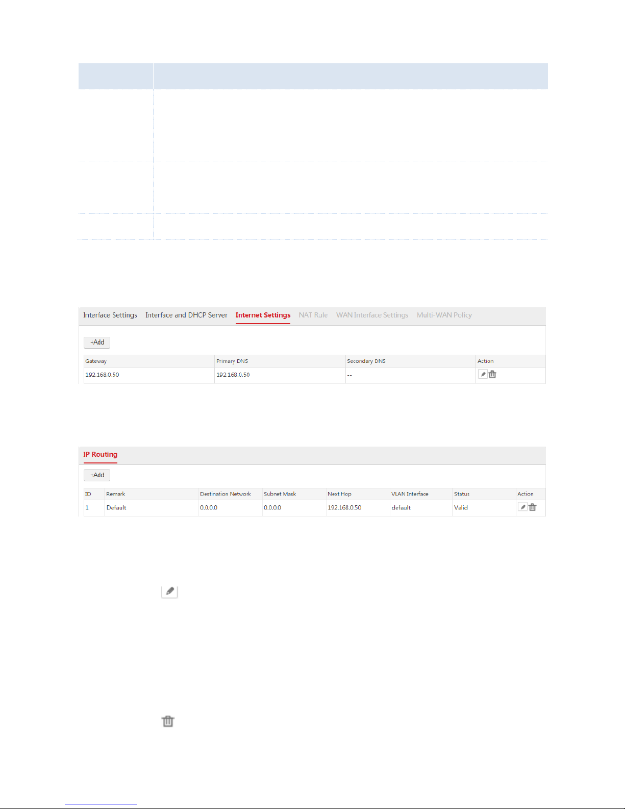
End: After the configuration is complete, you can choose Network Setting > Network Setting >
Internet Settings to view the configured rule. See the following figure.
Besides, the AC generates a default route. You can choose Network Setting > IP Routing to view the
route. See the following figure.
Modifying the Internet Settings
1. Choose Network Setting > Network Setting > Internet Settings.
2. Click the icon on the "Action" column.
3. Configure the parameters in the window.
4. Click Save.
Deleting the Internet Settings
1. Choose Network Setting > Network Setting > Internet Settings.
2. Click the icon on the "Action" column.
Page 29
28
WAN Interface Is Created
After creating the WAN interface, you can configure the internet settings. Before configuring the internet
settings, you need to recognize your internet connection type by referring to the following table or
contacting your ISP.
Internet
Connection Type
Remark
PPPoE
The ISP provides you a PPPoE user name and password.
DHCP
The ISP does not provide you any account information, or the ISP tells you that the internet
connection type is "DHCP".
Static IP
The ISP provides you some fixed IP addresses, such as IP address, subnet mask, gateway, and
DNS address.
PPPoE
1. Choose Network Setting > Network Setting > Internet Settings and find the WAN interface to be
configured.
2. Internet Connection Type: Select "PPPoE".
3. Bandwidth: Enter the bandwidth provided by your ISP. If you are uncertain, contace your ISP.
4. Username/Password: Enter the user name and password provided by your ISP.
5. Click OK.
6. Click Connect.
Wait a moment. When the Internet Connection Status is displayed as "Connected", the AC is
successfully connected to the internet. Besides, the AC generates a default route. You can choose
Network Setting > IP Routing to view the route. See the following figure.
Page 30

29
If the AC cannot connect to the internet, choose Network Setting > Network Setting > WAN Interface
Settings and try modifying the WAN Interface Settings.
DHCP
1. Choose Network Setting > Network Setting > Internet Settings and find the WAN interface to be
configured.
2. Internet Connection Type: Select "DHCP".
3. Bandwidth: Enter the bandwidth provided by your ISP. If you are uncertain, contace your ISP.
4. Click OK.
5. Click Connect.
Wait a moment. When the Internet Connection Status is displayed as "Connected", the AC is
successfully connected to the internet. Besides, the AC generates a default route. You can choose
Network Setting > IP Routing to view the route. See the following figure.
If the AC cannot connect to the internet, choose Network Setting > Network Setting > WAN Interface
Settings and try modifying the WAN Interface Settings.
Static IP
1. Choose Network Setting > Network Setting > Internet Settings and find the WAN interface to be
configured.
2. Internet Connection Type: Select "Static IP".
3. Bandwidth: Enter the bandwidth provided by your ISP. If you are uncertain, contace your ISP.
4. IP Address/Subnet Mask/Gateway/Primary DNS/Secondary DNS: Enter the fixed IP addresses
provided by your ISP.
5. Click OK.
6. Click Connect.
Page 31

30
Wait a moment. When the Internet Connection Status is displayed as "Connected", the AC is
successfully connected to the internet. Besides, the AC generates a default route. You can choose
Network Setting > IP Routing to view the route. See the following figure.
If the AC cannot connect to the internet, choose Network Setting > Network Setting > WAN Interface
Settings and try modifying the WAN Interface Settings.
1.3.3 Example of Internet Settings
WAN Interface Is Not Created
Networking Requirement
To locate network problems more correctly, the network administrator needs to make the AC connect to
the internet to ensure that the system time of the AC synchronizes with the internet time.
Assumption:
The ports of the switch connected to the router and AC do not configure VLAN function.
The router is connected to the internet.
The LAN IP address of the router is 192.168.0.50 and the router is a DNS proxy server.
Page 32

31
Network Topology
Procedure
To meet the requirements, configure the AC as follows.
1. Choose Network Setting > Network Setting > Internet Settings and configure the following
parameters.
2. Choose Network Setting > Network Setting > Interface Settings to ensure that "eth0" belongs to
VLAN 0.
3. Choose Network Setting > Network Setting > Interface and DHCP Server and create an interface
IP address belonging to the network segment of 192.168.0.50, which is used to communicate with
the gateway of the AC.
VLAN Interface
IP Address
Other Parameters
default
192.168.0.1/24
Keep the default value.
Internet
Router
Switch
LAN Port
Page 33

32
Verification
After the configuration is complete, the AC is connected to the internet and synchronizes its system time
with the internet time. The status of the default route is displayed as "Valid". You can choose Network
Setting > IP Routing to view the route.
WAN Interface Is Created
Networking Requirement
To locate network problems more correctly, the network administrator needs to make the AC connect to
the internet to ensure that the system time of the AC synchronizes with the internet time.
Assumption:
The bandwidth provided by the ISP is 50Mbps.
Both the PPPoE user name and password are "Nell".
Page 34

33
Network Topology
Procedure
Step 1: Configure eth3 as a WAN interface
1. Choose Network Setting > Network Setting > Interface Settings.
2. Find the interface "default" and click .
3. Physical Port: Unselect the box of the physical port to be configured as a WAN interface. In this
example, the physical port is "eth3".
4. Click Save.
Internet
VLAN Interface
Switch
Page 35

34
5. Choose Network Setting > Network Setting > Interface Settings and click Add.
6. Configure the parameters in the window.
Interface Type: Select "WAN Interface".
Physical Port: Select "eth3".
Interface Name: Set a name for the interface, such as "wan0".
7. Click Save.
Page 36

35
End: See the following figure.
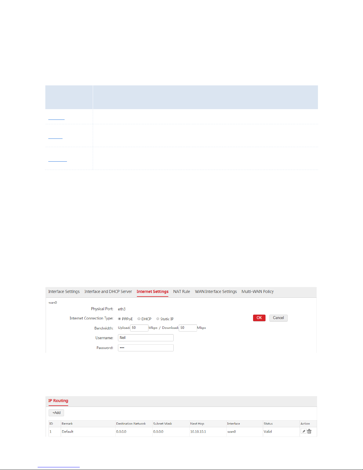
Step 2: Configure Internet Settings
1. Choose Network Setting > Network Setting > Internet Settings, find the WAN interface "wan0",
and configure the parameters as follows.
2. Internet Connection Type: Select "PPPoE".
3. Bandwidth: Enter the bandwidth provided by the ISP. In this example, both the upload and download
bandwidth are 50Mbps.
4. Username/Password: Enter the user name and password provided by your ISP. In this example, both
the user name and password are "Nell".
5. Click OK.
6. Click Connect.
Verification
Wait a moment. When the Internet Connection Status is displayed as "Connected", the AC is
successfully connected to the internet. Besides, the AC generates a default route. You can choose
Network Setting > IP Routing to view the route. See the following figure.
Page 37

36
1.4 NAT Rule
1.4.1 Overview
When you choose Network Setting > Network Setting > Interface Settings and add a WAN interface,
you can configure NAT-related rules, including NAT Rule, Virtual Server, and DMZ Host.
ி NAT Rule
When you configure Internet Settings correctly, this AC can access the internet. But if no NAT rule exists,
local computers connected to the AC cannot access the internet through this AC.
This AC can generate NAT rules automatically. When you add a WAN interface and configure Internet
Settings correctly, the AC can automatically add a NAT rule to translate all source IP addresses of the
default VLAN interface and to allow all computers connected to the AC to access the internet through this
AC.
Besides, when you add new VLAN interfaces, the AC automatically generates new NAT rules.
ி Virtual Server
By default, internet users cannot access any service on any of your local hosts. If you want to enable
internet users to access a particular service on a local host, enable this function and specify the IP
address and service port of the local host.
ி DMZ Host
If you set a local host as a DMZ host, internet users and this host can communicate with each other freely.
For example, if you are participating a video conference or an online game, you can set your computer
as the DMZ host for better video conferencing or online gaming experience.
Note: If you set a local computer as a DMZ host, the computer is not protected by the firewall of the
router and may be easily attacked by internet users. Therefore, enable the DMZ host function only when
necessary.
1.4.2 Configuring NAT-related Rules
Configuring NAT Rule
When you add a WAN interface and configure Internet Settings correctly, the AC can automatically add a
NAT rule to translate all source IP addresses of the default VLAN interface and to allow all computers
Page 38

37
connected to the AC to access the internet through this AC.
You are not recommended to manually configure a NAT rule, unless you want to disallow some
users to access the internet through this AC.
Adding a Rule
1. Log in to the AC's web UI and go to Network Setting > Network Setting > NAT Rule.
2. On the "NAT Rule" section, click Add.
3. Configure the parameters in the window.
4. Click Save.
Parameter Description
Parameter
Description
Name
The description of the configured NAT rule. Note: Duplicated names of NAT rules are not allowed.
Local VLAN
Interface
The interface that data packets come from.
Source IP Address
The network segment of a VLAN interface that needs to access the internet through WAN
interfaces of the AC.
ALL: It includes all network segments of the selected VLAN interface.
Manually: Manually enter a network segment that needs to access the internet through WAN
interfaces of the AC. And you need to set the subnet mask of the network segment.
Status
Enable or disable the configured rule.
End: When you add a NAT rule successfully, you can choose Network Setting > Network Setting >
NAT Rule > NAT Rule to view the rule. See the following figure.
Page 39

38
Modifying a Rule
1. Log in to the AC's web UI and go to Network Setting > Network Setting > NAT Rule.
2. On the "NAT Rule" section, find the NAT rule to be modified.
3. If you want to disable/enable a NAT rule, click the button / on "Status" column. If you want
to edit a NAT rule, click the button on "Action" column.
Deleting a Rule
1. Log in to the AC's web UI and go to Network Setting > Network Setting > NAT Rule.
2. On the "NAT Rule" section, find the NAT rule to be deleted, and click the button on the "Action"
column.
Configuring Virtual Server
By default, no virtual server rules exist on the AC.
Adding a Rule
1. Log in to the AC's web UI and go to Network Setting > Network Setting > NAT Rule.
2. On the "Virtual Server" section, click Add.
3. Configure the parameters in the window.
4. Click Save.
Page 40

39
Parameter Description
Parameter
Description
Name
The description of the configure virtual server rule. Note: Duplicated names of virtual server rules are
not allowed.
WAN Interface
The WAN interface that internet users need to use to access the local server on the LAN. A server in
this context means a software program installed on a computer, such as a FTP server and a web
server.
ALL: It includes all WAN interfaces of the AC. In this circumstance, internet users can access the
available local server using any WAN interface.
External Port
The port that internet users need to use to access the local server on the LAN.
Local Host IP
The IP address of the local host that installs a server.
Local Port
The enabled port of the local server.
Protocol
The protocol that the local server uses. ALL: It includes TCP and UDP. If you are uncertain about the
protocol, choose "ALL".
Status
Enable or disable the configured rule.
End: When you add a virtual server rule successfully, you can choose Network Setting > Network
Setting > NAT Rule > Virtual Server to view the rule. See the following figure.
Page 41

40
Modifying a Rule
1. Log in to the AC's web UI and go to Network Setting > Network Setting > NAT Rule.
2. On the "Virtual Server" section, find the rule to be modified.
3. If you want to disable/enable a rule, click the button / on the "Status" column. If you want to
edit a rule, click the button on the "Action" column.
Deleting a Rule
1. Log in to the AC's web UI and go to Network Setting > Network Setting > NAT Rule.
2. On the "Virtual Server" section, find the rule to be deleted and click on the "Action" column.
Configuring DMZ Host
By default, this function is disabled on the AC.
To enable a DMZ host:
1. Log in to the web UI of the AC, go to Network Setting > Network Setting > NAT Rule, and find
"DMZ Host" section.
2. On the WAN interface to enable the DMZ host function, click Enable.
3. IP Address: Enter the IP address of the local host that needs to be a DMZ host.
4. Save your settings.
Page 42

41
1.4.3 Example of NAT-related Rule
Example of NAT Rule
Networking Requirement
When you add WAN interfaces and configure Internet Settings correctly, all computers connected to the
VLAN interfaces of the AC can access the internet through the WAN interfaces of the AC. Assume that
two network segments exist in the VLAN interface "default":
192.168.10.0/24 is used by APs.
192.168.16.0/24 is used by users.
Requirement: Users on the network segment 192.168.16.0/24 can access the internet through the AC.
APs on the network segment 192.168.10.0/24 cannot access the internet through the AC.
Network Topology
Procedure
1. Log in to the web UI of the AC and go to Network Setting > Network Setting > NAT Rule.
2. On the "NAT Rule" section, find the default rule "[def_default]" and click on the "Action" column.
Internet
VLAN
Interface
WAN Interface
Core Switch
PoE Switch
User
Page 43

42
3. Modify the parameters as follows.
Source IP Address: Select Manually and enter 192.168.16.0.
Subnet Mask: Enter 255.255.255.0.
4. Click Save.
End: See the following figure.
Verification
Set your computer to the network segment of 192.168.10.0/24 and verify that you cannot access the
internet.
Then use your computer to automatically obtain IP address. Verify that your computer is on the network
segment of 192.168.16.0/24 and you can access the internet.
Page 44

43
Example of Virtual Server
Networking Requirement
A hotel has established a network using AC3000. The AC is connected to the internet and provides
internet access for local users. The hotel has a local web server which needs to be accessed by internet
users, especially the hotel employees on a business trip.
To meet the requirements, you can use the virtual server function of the AC. Assume that the port
enabled for internet users to access the web server is 80. Other assumptions are shown on the following
network topology.
Network Topology
Procedure
1. Log in to the AC's web UI and go to Network Setting > Network Setting > NAT Rule.
2. On the "Virtual Server" section, click Add.
3. Configure the parameters as follows.
Internet
Internet User
VLAN Interface
Core Switch
PoE Switch
Local User
Web Server
IP: 192.168.0.250
Port: 8090
Page 45

44
Name: Enter a description for this rule, such as web server.
WAN Interface: Select the WAN interface that internet users need to use to access the web server.
In this example, it is WAN0.
External Port: Enter the port that internet users need to use to access the web server. In this
example, it is 80.
Local Host IP: Enter the IP address of the web server. In this example, it is 192.168.0.250.
Local Port: Enter the enabled port of the web server. In this example, it is 8090.
Protocol: Select ALL or TCP. (A web server uses the protocol TCP.)
Status: Select Enable.
4. Click Save.
End: See the following figure.
Verification
If the virtual server is configured successfully, internet users can use http://WAN IP address:external port
to access the web server. In this example, internet users can use http://202.105.11.22:80 to access the
web server.
Page 46

45
Configuration Tip
After you complete the virtual server configuration, if internet users still cannot access the web server,
you can successively try the following ways to solve your problem.
Ensure that the AC obtains a public IP address on the WAN0 interface and the local port
configured in the virtual server rule is the port of the web server.
Disable the system firewall, anti-virus programs, and security guards on the web server because
they may prohibit internet users to access the web server.
Manually configure the IP address of the web server. If no, the web server may dynamically obtain
a changeable IP address, which can cause server interrupt.
Example of DMZ Host
Networking Requirement
A hotel has established a network using AC3000. The AC is connected to the internet and provides
internet access for local users. The hotel has a local web server which needs to be accessed by internet
users, especially the hotel employees on a business trip.
To meet the requirements, you can use the DMZ host function of the AC.
Page 47

46
Network Topology
Procedure
1. Log in to the web UI of the AC and go to Network Setting > Network Setting > NAT Rule.
2. On the "DMZ Host" section, choose WAN0 to configure.
Select Enable.
IP Address: Enter the IP address of the web server 192.168.0.250.
3. Save your settings.
Verification
If the configuration is successful, internet users can use http://WAN IP address to access the web server.
In this example, internet users can use http://202.105.11.22 to access the web server.
Internet User
Local User
VLAN Interface
Core Switch
PoE Switch
Web Server
IP: 192.168.0.250
Internet
Page 48

47
Configuration Tip
After you complete the virtual server configuration, if internet users still cannot access the web server,
you can successively try the following ways to solve your problem.
Ensure that the AC obtains a public IP address on the WAN0 interface.
Disable the system firewall, anti-virus programs, and security guards on the web server because
they may prohibit internet users to access the web server.
Manually configure the IP address of the web server. If no, the web server may dynamically obtain
a changeable IP address, which can cause server interrupt.
1.5 WAN Interface Settings
When you correctly complete the configuration of Create WAN Interface, Internet Settings, and creating
NAT rules, if local computers connected to the AC still cannot access the internet, you can try changing
the WAN interface settings to solve your problem.
To go to the WAN Interface Settings page, click Network Setting > Network Setting > WAN Interface
Settings.
1.5.1 WAN Speed
In general, you are recommended to keep the WAN speed as the default value. But if the Internet
Connection Status of a WAN interface on the Network Setting > Network Setting > Internet Settings
page is displayed “The physical port is not connected", please first verify that:
The WAN interface of the AC is connected to an upstream device using an Ethernet cable and the
connected interface of the upstream device works properly.
The Ethernet cable connected to the WAN interface of the AC works properly.
After the verification, if the problem persists, change the WAN speed of the WAN interface to "10M Half
Duplex" or "10M Full Duplex".
In other circumstances, you are recommended to keep the WAN speed as the default value "Auto".
Page 49

48
1.5.2 MTU
Maximum Transmission Unit (MTU) indicates the maximum size of a packet that can be transmitted by a
network device. In general, you are recommended to keep the MTU as the default value "Auto". But if
you encounter any of the following problems:
Some websites are not accessible or some secure websites cannot be displayed properly (such
as the login pages of online banking websites and Alipay’s website).
Emails cannot be received or servers such as FTP and POP servers are not accessible.
You can try gradually reducing the value (recommended range: 1400 to 1500) to find the suitable value
that does not lead to the problem.
MTU Value
Usage
1500
It is the most common value for non-PPPoE connections and non-VPN connections.
1492
It is used for PPPoE connections.
1472
It is the maximum value for the pinging function. (If a greater value is used, packets are fragmented.)
1468
It is used for DHCP, which assigns dynamic IP addresses.
1436
It is used for VPNs or PPTP.
1.5.3 MAC Address
After you complete internet settings, if the Internet Connection Status of the WAN interface on the
Network Setting > Network Setting > Internet Settings page is always displayed "Connecting...", it
may be that your ISP binds your internet account to the MAC address of the computer that is able to
access the internet. If so, only that computer can access the internet using the internet account. The
computer refers to the one used to verify your internet accessibility after your ISP creates the account for
you.
You can try MAC address cloning method 1 or 2 described in the following section to resolve the
problem.
Method 1:
1. Connect the computer with internet accessibility to the AC, log in to the web UI of the AC, and go to
Network Setting > Network Setting > WAN Interface Settings.
2. On the WAN interface to clone the MAC address, find MAC Address, and select "Clone Local MAC".
3. Click Save.
Page 50

49
Method 2:
1. If you connect a computer without internet accessibility to the AC, log in to the web UI of the AC, and
go to Network Setting > Network Setting > WAN Interface Settings.
2. On the WAN interface to clone the MAC address, find MAC Address, select "Manual", and enter the
MAC address of the computer with internet accessibility.
3. Click OK.
If you want to restore the MAC address of a WAN interface to its default value, log in to the web UI of the AC,
go to Network Setting > Network Setting > WAN Interface Settings, find MAC Address section of the
WAN interface, and select "Default MAC".
1.6 Multi-WAN Policy
1.6.1 Overview
The AC supports a maximum of N-1 WAN interfaces. N is the number of physical ports of the AC. When
multiple WAN interfaces works simultaneously, you are recommended to set the multi-WAN policy to
improve the bandwidth usage of the AC. The AC supports the following two kinds of multi-WAN policies,
you can select one of them as required.
Page 51

50
ி Intelligent Load Balance
It is the default policy. The AC can automatically find the WAN interface with lower bandwidth usage to
communicate with the internet so as to decrease the labour cost. The bandwidth of all WAN interfaces
must be correctly configured on the Network Setting > Network Setting > Internet Settings page.
For example, the AC has two WAN interfaces: WAN1 and WAN2. The bandwidth usage of WAN1 and
WAN2 are 90% and 20% respectively. In this case, when users have new internet access requests, the
AC uses WAN2 to forward the requests.
ி Customized Policy
In this case, you can specify WAN interfaces to forward data packets from certain network segments.
The data packets from disabled policies or not covered in the customized policies can use the intelligent
load balance policy. If the WAN interface matching a customized policy is disconnected from the
upstream device, the data packets matching the customized policy can use the intelligent load balance
policy.
1.6.2 Customized Multi-WAN Policy
Enabling the Customized Policy Function
1. Choose Network Setting > Network Setting > Multi-WAN Policy.
2. Multi-WAN Policy: Select "Customized Policy".
3. Click OK.
Then you can add rules of customized multi-WAN policy.
Page 52

51
Configuring Customized Policies
Creating a Customized Policy
1. Choose Network Setting > Network Setting > Multi-WAN Policy.
2. Click Add.
3. Configure the parameters in the window.
4. Click Save.
Parameter Description
Parameter
Description
Status
Enable or disable the rule.
Enable: The data packets from certain NAT rule will be forwarded by a specified WAN interface.
If the specified WAN interface is disconnected from the upstream device, the data packets
matching the rule can use the intelligent load balance policy.
Disable: The data packets matching the rule use the intelligent load balance policy. Data
packets not covered in customized policies use the intelligent load balance policy.
NAT Rule
Select a NAT rule to specify the data packets from the local network. You can configure NAT rules on
the Network Setting > Network Setting > NAT Rule page.
WAN Interface
Select the WAN interface to forward specified data packets.
End: After the configuration is complete, you can view the information on the Network Setting >
Network Setting > Multi-WAN Policy page. See the following figure.
Page 53

52
Modifying a Rule
1. Choose Network Setting > Network Setting > Multi-WAN Policy.
2. Find the policy to be modified and click .
Deleting a Rule
1. Choose Network Setting > Network Setting > Multi-WAN Policy.
2. To delete one policy, find the policy and click . To delete multiple policies, select the policies and
click Delete.
1.6.3 Example of Customized Multi-WAN Policy
Networking Requirement
A hotel uses AC3000 to establish a network and already applies for two internet connection lines from
ISP1 and ISP2. Requirement:
Computers from VLAN 50 (IP address range: 192.168.50.100~192.168.50.200) access the
internet through ISP1.
Computers from VLAN 60 (IP address range: 192.168.60.100~192.168.60.200) access the
internet through ISP2.
We can use the customized multi-WAN policy function to meet the requirement.
In this example, assume that the DNS address is 202.96.134.133.
Page 54

53
Network Topology
Procedure
I. Configure AC
Step 1: Configure VLAN Interface
1. Configure a VLAN interface to communicate with VLAN 50.
1) Choose Network Setting > Network Setting > Interface Settings.
2) Click Add.
3) Configure the parameters in the window.
Interface Type: Select "VLAN Interface".
Physical Port: Select the port connected to the switch, which is "eth0".
Interface Name: Set a name for the VLAN interface, such as "vlan50".
VLAN ID: Enter "50".
4) Click Save.
wan0: ISP1
wan1: ISP2
Internet
eth0: VLAN Interface
Switch
Page 55

54
2. Configure a VLAN interface to communicate with VLAN 60.
1) Choose Network Setting > Network Setting > Interface Settings.
2) Click Add.
3) Configure the parameters in the window.
Interface Type: Select "VLAN Interface".
Physical Port: Select the port connected to the switch, which is "eth0".
Interface Name: Set a name for the VLAN interface, such as "vlan60".
VLAN ID: Enter "60".
4) Click Save.
Page 56

55
Step 2: Configure Interface and DHCP Server
1. Configure a DHCP server to communicate with VLAN 50.
1) Choose Network Setting > Network Setting > Interface and DHCP Server.
2) Click Add.
3) Configure the parameters in the window.
VLAN Interface: Select "vlan50".
IP Address: Set an IP address for the VLAN interface, such as "192.168.50.1".
Subnet Mask: You can keep the default value.
DHCP Server: Select "Enable".
Assign IP to: Select "User".
Remark: Set a name for the DHCP server, such as "user50".
Gateway: Enter the IP address of the VLAN interface, which is "192.168.50.1".
Primary DNS: Enter the DNS server address of DNS proxy server address, which is
"202.96.134.133".
Start IP: Enter the start IP address of the DHCP address pool, such as "192.168.50.100".
End IP: Enter the end IP address of the DHCP address pool, such as "192.168.50.200".
4) Click Save.
Page 57

56
2. Configure a DHCP server to communicate with VLAN 60.
1) Choose Network Setting > Network Setting > Interface and DHCP Server.
2) Click Add.
3) Configure the parameters in the window.
VLAN Interface: Select "vlan60".
IP Address: Set an IP address for the VLAN interface, such as "192.168.60.1".
Subnet Mask: You can keep the default value.
DHCP Server: Select "Enable".
Assign IP to: Select "User".
Remark: Set a name for the DHCP server, such as "user60".
Gateway: Enter the IP address of the VLAN interface, which is "192.168.60.1".
Primary DNS: Enter the DNS server address of DNS proxy server address, which is
"202.96.134.133".
Start IP: Enter the start IP address of the DHCP address pool, such as "192.168.60.100".
End IP: Enter the end IP address of the DHCP address pool, such as "192.168.60.200".
4) Click Save.
Page 58

57
Step 3: Configure Multi-WAN Policy
1. Enable Customized Policy.
1) Choose Network Setting > Network Setting > Multi-WAN Policy.
2) Multi-WAN Policy: Select "Customized Policy".
3) Click OK.
2. Create a customized policy to make the data packets from VLAN 50 are forwarded to wan0.
1) Choose Network Setting > Network Setting > Multi-WAN Policy and click Add.
2) Configure the parameters in the window.
Status: Select Enable.
NAT Rule: Select the NAT rule used by computers from VLAN 50, which is "[def_vlan50]".
WAN Interface: Select "wan0".
3) Click Save.
3. Create a customized policy to make the data packets from VLAN 60 are forwarded to wan0.
1) Choose Network Setting > Network Setting > Multi-WAN Policy and click Add.
2) Configure the parameters in the window.
Page 59

58
Status: Select Enable.
NAT Rule: Select the NAT rule used by computers from VLAN 60, which is "[def_vlan60]".
WAN Interface: Select "wan1".
3) Click Save.
II. Configure Switch
Configure the 802.1Q VLAN function on the switch. Set the port connected to the VLAN 50 network as
an access port and make the port to allow VLAN 50 to pass through. Set the port connected to the VLAN
60 network as an access port and make the port to allow VLAN 60 to pass through. Set the port
connected to the AC as a trunk port and make the port to allow VLAN 1,50,60 to pass through. The
details are shown as follows.
The port connected to
VLAN ID
Port Type
PVID
VLAN 50 network
50
Access
50
VLAN 60 network
60
Access
60
AC
1,50,60
Trunk
1
Verification
When the two internet connection lines work properly, if you connect your computer to VLAN 50 network
and perform the command tracert www.google.com, you can view that the second route is the gateway
of the wan0. If you connect your computer to VLAN 60 network and perform the command tracert
www.google.com, you can view that the second route is the gateway of the wan1.
Page 60

59
2 IP Routing
2.1 Overview
On the page IP Routing, you can specify different routes for the AC to reach different destinations. The
AC supports creating a maximum of 512 routes. Through this function, you can meet the following
requirements:
The AC can access different networks simultaneously, such as the internet and enterprise
network.
Users connected to the AC can access different networks simultaneously, such as the internet
and enterprise network.
2.2 Configuring IP Routing
To go to the IP Routing page, click Network Setting > IP Routing. The default page is shown as
follows.
If the internet settings are configured successfully, the AC generates a default route on this page. See
the following figure.
Creating an IP Route
1. Choose Network Setting > IP Routing.
2. Click Add.
3. Configure the parameters in the window.
4. Click Save.
Page 61

60
Parameter Description
Parameter
Description
Remark
The description of the route.
Only Chinese characters, letters, digits, underscores, and dashes are allowed. Bland is not
allowed. Range: 1 - 16 characters. The AC supports creating a maximum of of 512 routes.
Destination
Network
The network segment of the destination network.
Subnet Mask
The subnet mask of the destination network.
Next Hop
The IP address of the next network node to which the packet is to be sent on the way to its final
destination.
Interface
The used interface when the AC accesses the destination network.
End: After the configuration is complete, you can view the information on the Network Setting > IP
Routing page. See the following figure.
The status has two states: Valid and Invalid. "Valid" indicates that the route is configured correctly. "Invalid"
Page 62

61
indicates that the route is configured incorrectly, if so, verity that the destination network, next hop, and
interface are configured correctly.
Modifying an IP Route
1. Choose Network Setting > IP Routing.
2. Find the route to be modified and click .
3. Configure the parameters in the window.
4. Click Save.
Deleting an IP Route
1. Choose Network Setting > IP Routing.
2. Find the route to be modified and click .
The default route is not allowed to be modified or deleted.
2.3 Example of IP Routing
2.3.1 WAN Interface Is Not Created
Networking Requirement
The AC is connected to two networks: the internet and the enterprise network. All users connected to the
AC need to access the internet and the internal server of the enterprise network simultaneously.
Assumption:
The network segment of the server: 172.16.100.0/24.
The LAN IP address of the router connected to the server (Router1): 192.168.100.100.
The LAN IP address of the router connected to the internet (Router2): 192.168.200.100. This
router is a DNS proxy server.
The switch and APs are not configured VLAN function. All users do not belong to any VLAN
networks.
Both the two routers support creating NAT rules.
Page 63

62
Network Topology
Procedure
I. Configure AC
Procedure:
Step 1: Configure VLAN Interface
Configure the VLAN interface on the Network Setting > Network Setting > Interface Settings page.
According to the networking requirement, the VLAN interface of the AC used to communicate with the
APs and routers does not need to configure VLAN ID. So we can use the default VLAN interface.
Administrator
User
Internal Server
Router1
Router2
Switch
Internet
Page 64

63
Step 2: Configure Interface and DHCP Server
Choose Network Setting > Network Setting > Interface and DHCP Server and create four DHCP
servers used to communicate with the APs, the users, Route1, and Router2 respectively.
1. Configure the DHCP server used to communicate with the APs
As the AC provides a default DHCP server used to assign IP addresses to APs, so we can use the
default DHCP server.
2. Configure the DHCP server used to communicate with the users
1) Click Add.
2) Configure the parameters in the window.
VLAN Interface: Select the configured VLAN interface from Step 1, which is "default".
IP Address: Set an IP address for the VLAN interface, such as "192.168.6.1".
Subnet Mask: You can keep the default value.
DHCP Server: Select "Enable".
Assign IP to: Select "User".
Remark: Set a name for the DHCP server, such as "user".
Gateway: Enter the IP address of the VLAN interface, which is "192.168.6.1".
Primary DNS: Enter the DNS server address or DNS proxy server address, which is
"192.168.200.100" in this example.
Start IP: Enter the start IP address of the DHCP address pool, such as "192.168.6.100".
End IP: Enter the end IP address of the DHCP address pool, such as "192.168.6.200".
3) Click Save.
Page 65

64
Tip: The AC is not a DNS proxy server when no WAN interface is created. In this example, the primary
DNS address is the LAN IP address of the router connected to the internet (Router2).
3. Configure the DHCP server used to communicate with the Router1
1) Click Add.
2) Configure the parameters in the window.
VLAN Interface: Select the configured VLAN interface from Step 1, which is "default".
IP Address: Set an IP address for the VLAN interface that is on the network segment of the LAN
IP address of Router1, such as "192.168.100.1".
Subnet Mask: You can keep the default value.
3) Click Save.
Page 66

65
4. Configure the DHCP server used to communicate with the Router2
1) Click Add.
2) Configure the parameters in the window.
VLAN Interface: Select the configured VLAN interface from Step 1, which is "default".
IP Address: Set an IP address for the VLAN interface that is on the network segment of the LAN
IP address of Router2, such as "192.168.200.1".
Subnet Mask: You can keep the default value.
3) Click Save.
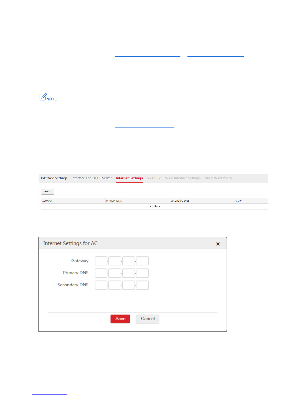
Step 3: Configure Internet Settings
1. Choose Network Setting > Network Setting > Internet Settings.
Page 67

66
2. Click Add.
3. Configure the parameters in the window.
Gateway: Set the IP address of the default gateway of the AC, which is ""192.168.200.100" in this
example.
Primary DNS: Enter the DNS server address or DNS proxy server address, which is
"192.168.200.100" in this example.
4. Click Save.
Step 4: Configure IP Routing
1. Choose Network Setting > IP Routing.
2. Click Add.
3. Configure the parameters in the window.
Remark: Set a description for the route, such as "Internal".
Destination Network: Enter the network segment of the internal server, which is "172.16.100.0" in
this example.
Subnet Mask: Enter the subnet mask of the internal server, which is "255.255.255.0" in this example.
Next Hop: Enter the IP address of the next network node to which the packet is to be sent on the way
to the internal server. In this example, it is the LAN IP address of Router1: 192.168.100.100.
Interface: Enter the used interface when the AC accesses the internal server, which is "default" in
this example.
4. Click Save.
Page 68

67
In this example, we can use the default SSID policy. When the APs get online, the default SSID policy
will be delivered to the APs. Then, the users can automatically obtain the IP address information.
Network segment: 192.168.6.0/24, gateway: 192.168.6.1, DNS: 192.168.200.100.
II. Configure Router
1. Configure static routes on the two routers.
Configured Router
Destination Network
Next Hop
Interface
Router1
192.168.6.0/24
192.168.100.1
LAN
Router2
192.168.6.0/24
192.168.200.1
LAN
2. Configure NAT rules on the two routers to allow the users to access the internal server and the
internet.
Configured Router
IP Address
Subnet Mask
Interface
Router1
192.168.6.0
255.255.255.0
WAN
Router2
192.168.6.0
255.255.255.0
WAN
Verification
After the configuration is complete, both the AC and the users can access the internet and the internal
server of the enterprise network simultaneously.
Page 69

68
2.3.2 WAN Interface Is Created
Networking Requirement
The AC is connected to two networks: the internet and the enterprise network. All users connected to the
AC need to access the internet and the internal server of the enterprise network simultaneously.
Assumption:
The network segment of the server: 172.16.100.0/24.
The LAN IP address of the router connected to the server (Router1): 192.168.100.100.
The switch and APs are not configured VLAN function. All users do not belong to any VLAN
networks.
The applied bandwidth is 50Mbps, and both the PPPoE user name and password are "Nell".
In this example, assume that the DNS address is 202.96.134.133.
Network Topology
Internet
eth0: VLAN Interface
eth3: WAN Interface
Administrator
Switch
User
Router
Internal Server
Page 70

69
Procedure
All the configurations are set on the AC.
Procedure:
Step 1: Create WAN Interface
1. Remove the physical port as a WAN interface from the previous VLAN interface.
1) Choose Network Setting > Network Setting > Interface Settings.
2) Find the VLAN interface such as "default" and click .
3) Physical Port: Unselect the box of the physical port as a WAN interface. In this example, the
physical port is "eth3".
4) Click Save.
2. Create WAN Interface
1) Choose Network Setting > Network Setting > Interface Settings and click Add.
2) Configure the parameters in the window.
Interface Type: Select "WAN Interface".
Physical Port: Select the physical port to be set to a WAN interface, which is "eth3" in this
example.
Interface Name: Set a name for the interface, such as "wan0".
3) Click Save.
Page 71

70
Step 2: Configure Internet Settings
1. Choose Network Setting > Network Setting > Internet Settings.
2. Internet Connection Type: Select "PPPoE".
3. Bandwidth: Enter the bandwidth provided by the ISP. In this example, both the upload and download
bandwidth are "50Mbps".
4. Username/Password: Enter the user name and password provided by your ISP. In this example, both
the user name and password are "Nell".
5. Click OK.
6. Click Connect.
Step 3: Configure VLAN Interface
Configure the VLAN interface on the Network Setting > Network Setting > Interface Settings page.
According to the networking requirement, the eth0 port of the AC does not need to configure VLAN ID
and belongs to the default VLAN interface. So we can use the default VLAN interface.
Page 72

71
Step 4: Configure Interface and DHCP Server
Choose Network Setting > Network Setting > Interface and DHCP Server and create two DHCP
servers used to communicate with the APs and the users/router respectively.
Set the IP addresses of the users to belong to the network segment of the LAN IP address of the router. In this
case, the router does not need to support the function of creating NAT rules. Otherwise, the router must
support the function.
1. Configure the DHCP server used to communicate with the APs
As the AC provides a default DHCP server used to assign IP addresses to APs, so we can use the
default DHCP server.
2. Configure the DHCP server used to communicate with both the users and the router
1) Choose Network Setting > Network Setting > Interface and DHCP Server and click Add.
2) Configure the parameters in the window.
VLAN Interface: Select the configured VLAN interface from Step 3, which is "default".
IP Address: Set an IP address for the VLAN interface that is on the network segment of the LAN
IP address of Router1, such as "192.168.100.1".
Subnet Mask: You can keep the default value.
DHCP Server: Select "Enable".
Assign IP to: Select "User".
Remark: Set a name for the DHCP server, such as "user".
Gateway: Enter the IP address of the VLAN interface, which is "192.168.100.1".
Primary DNS: Enter a DNS server address or DNS proxy server address, which is
"202.96.134.133" in this example.
Page 73

72
Start IP: Set a start IP address of the DHCP address pool, such as "192.168.100.150".
End IP: Set an end IP address of the DHCP address pool, such as "192.168.100.250".
3) Click Save.
Tip: Assume that the primary DNS address is 202.96.134.133.
Step 5: Configure IP Routing
1. Choose Network Setting > IP Routing.
2. Click Add.
3. Configure the parameters in the window.
Remark: Set a description for the route, such as "Internal".
Destination Network: Enter the network segment of the internal server, which is "172.16.100.0" in
this example.
Subnet Mask: Enter the subnet mask of the internal server, which is "255.255.255.0" in this example.
Next Hop: Enter the IP address of the next network node to which the packet is to be sent on the way
to the internal server. In this example, it is the LAN IP address of Router1: 192.168.100.100.
Interface: Enter the used interface when the AC accesses the internal server, which is "default" in
this example.
Page 74

73
4. Click Save.
In this example, we can use the default SSID policy. When the APs get online, the default SSID policy
will be delivered to the APs. Then the users can obtain the IP address information. Network
segment:192.168.100.0/24, gateway: 192.168.100.1, DNS: 202.96.134.133.
Verification
After the configuration is complete, both the AC and the users can access the internet and the internal
server of the enterprise network simultaneously.
Page 75

74
3 Example of Network Setting
3.1 WAN Interface Is Not Created
Networking Requirement
The AC is connected to two networks: the internet and the enterprise network. Requirement:
The router connected to the internet (Router2) belongs to VLAN 200 network, and the router
connected to the enterprise network (Router1) belongs to VLAN 100.
The management VLAN ID of the APs is VLAN 5.
The users belong to VLAN 6 network.
The users can access the internet and the internal server of the enterprise simultaneously.
Assumption:
All the APs are restored to the factory state.
The network segment of the enterprise network: 172.16.100.0/24. The LAN IP address of the
router connected to the server (Router1): 192.168.100.100.
The LAN IP address of the router connected to the internet (Router2): 192.168.200.100. Router2
is a DNS proxy server.
Both the two routers support creating NAT rules.
Page 76

75
Network Topology
Procedure
I. Manage AP
Step 1: Modify Management VLAN of AP
1. Choose AP Management > Modify AP.
2. Select the APs to be managed and click Advanced Setting.
3. Set the Management VLAN to 5.
4. Click Save.
Internet
Administrator
Internet Server
Router1
Switch
Router2
User
AP
Management VLAN: 5
SSID: VIP
Page 77

76
5. Select the APs to be managed and click Reboot. The settings take effect when the APs finish the
reboot process.
Step 2: Configure VLAN Interface
Choose Network Setting > Network Setting > Interface Settings and configure two VLAN interfaces
used to communicate with the administrator and the APs respectively.
1. Configure the VLAN interface used to communicate with the administrator.
According to the networking requirement, the VLAN interface of the AC communicated with the
administrator does not need to configure VLAN ID. We can use the default VLAN interface.
2. Configure the VLAN interface used to communicate with the APs.
1) Click Add.
2) Configure the parameters in the window.
Interface Type: Select "VLAN Interface".
Physical Port: Select the port connected to the switch, which is "eth0".
Interface Name: Set a name for the VLAN interface, such as "vlan5".
VLAN ID: Enter the management VLAN ID of the APs, which is "5" in this example.
Page 78

77
3) Click Save.
Step 3: Configure Interface and DHCP Server
Choose Network Setting > Network Setting > Interface and DHCP Server and configure two DHCP
servers used to communicate with the administrator and the APs respectively.
1. Configure the DHCP server used to communicate with the administrator
1) Choose Network Setting > Network Setting > Interface Settings and click Add.
2) Configure the parameters in the window.
VLAN Interface: Select the VLAN interface configured in "Configure the VLAN interface used to
communicate with the administrator" from Step 2, which is "default" in this example.
IP Address: Set an IP address for the VLAN interface, such as "192.168.0.1".
Subnet Mask: You can keep the default value.
3) Click Save.
Page 79

78
2. Configure the DHCP server used to communicate with the APs
1) Choose Network Setting > Network Setting > Interface Settings and click Add.
2) Configure the parameters in the window.
VLAN Interface: Select “vlan5”.
IP Address: Set an IP address for the VLAN interface, such as "192.168.5.1".
Subnet Mask: You can keep the default value.
DHCP Server: Select "Enable".
Remark: Set a name for the DHCP server, such as “AP”.
Primary DNS: In this example, you can set the primary DNS address as the DHCP server IP
address "192.168.5.1".
Start IP: Enter the start IP address of the DHCP address pool, such as "192.168.5.100".
End IP: Enter the end IP address of the DHCP address pool, such as "192.168.5.200".
3) Click Save.
Page 80

79
Step 4: Configure Switch
On the switch, set the ports connected to the APs and the AC to trunk ports, set the PVID of the two ports
to 1, and allow VLAN 1,5 to pass through the two ports. The details are shown in the following table.
Page 81

80
The port connected to
VLAN ID
Port Type
PVID
AP
1,5
Trunk
1
AC
1,5
Trunk
1
After the above configuration, the AC can mange the APs whose management VLAN ID are 5.
II. Manage User
Log in to the web UI of the AC and follow the steps.
Step 1: Configure VLAN Interface
1. Log in to the web UI of the AC and go to Network Setting > Network Setting > Interface Settings.
2. Click Add.
3. Configure the parameters in the window.
Interface Type: Select "VLAN Interface".
Physical Port: Select the port connected to the switch, which is "eth0".
Interface Name: Set a name for the VLAN interface, such as "vlan6".
VLAN ID: Enter the VLAN ID of the users' VLAN network, which is "6".
4. Click Save.
Page 82

81
Step 2: Configure Interface and DHCP Server
1. Log in to the web UI of the AC and go to Network Setting > Network Setting > Interface and
DHCP Server.
2. Click Add.
3. Configure the parameters in the window.
VLAN Interface: Select the configured VLAN interface from Step 1, which is "vlan6".
IP Address: Set an IP address for the VLAN interface, such as "192.168.6.1".
Subnet Mask: You can keep the default value.
DHCP Server: Select "Enable".
Assign IP to: Select "User".
Remark: Set a name for the DHCP server, such as "user".
Gateway: Enter the IP address of the VLAN interface, which is "192.168.6.1".
Primary DNS: Enter the DNS server address or DNS proxy server address. In this example, it is
"192.168.200.100".
Start IP: Enter the start IP address of the DHCP address pool, such as "192.168.6.100".
End IP: Enter the end IP address of the DHCP address pool, such as "192.168.6.200".
4. Click Save.
Page 83

82
Note: This AC series does not support DNS proxy function when no WAN interface is created. The
primary DNS address must be a DNS server address or DNS proxy server address. In this example, it is
the LAN IP address of the router connected to the internet: 192.168.200.100.
Step 3: Configure SSID Policy
1. Choose Wireless Policy > SSID Policy > SSID Policy.
2. Click Add.
3. Configure the parameters in the window.
Policy: Set a policy name for the SSID policy, such as "VIP".
SSID: Set a name for the wireless network, such as "VIP".
Security Mode: It is recommended to select "WPA2-PSK".
Encryption: It is recommended to select "AES".
Password: Set a password for wireless network, such as "12345678".
Forwarding Mode: Select "Centralized".
VLAN Interface: Select the interface name of the VLAN interface configured in Step 1, which is
"vlan6" in this example.
4. Click Save.
Page 84

83
Step 4: Configure SSID Group
1. Choose AP Management > SSID Group.
2. Click Add.
3. Configure the parameters in the window.
SSID Group: Set a name for the SSID group, such as "VIP".
SSID Policy: Select the configured SSID policy from Step 3, which is "VIP".
4. Click Save.
Page 85

84
Step 5: Configure AP Group
1. Choose AP Management > AP Group.
2. Click Add.
3. Configure the parameters in the window.
AP Group: Set a name for the AP group, such as "VIP".
SSID Group: Select the configured SSID group from Step 4, which is "VIP".
4. Click Save.
Page 86

85
Step 6: Batch Group
1. Choose AP Management > Modify AP.
2. Select the APs that need the SSID policy and click "Batch Group".
3. AP Group: Select the configured AP group from Step 5, which is "VIP".
4. Click Save.
End: After the configuration is complete, when the users connect to the "VIP" WiFi network, they can
automatically obtain the IP address information from the AC. Network segment: 192.168.6.0, gateway:
192.168.6.1, and DNS: 192.168.200.100.
You can view the user information on the Monitoring > Client List > DHCP Client List page. See the
following figure.
III. Configure Router
1. Configure IP routing rules on the two routers.
Configured Router
Destination Network
Next Hop
Interface
Router1
192.168.6.0/24
192.168.100.1
LAN
Router2
192.168.6.0/24
192.168.200.1
LAN
2. Configure NAT rules on the two routers to allow the users to access the internet and the internal
server of the enterprise.
Note: If the users need to access the internet and the enterprise network, both the two routers must
Page 87

86
support the function of creating NAT rules.
Configured Router
IP Address
Subnet Mask
Interface
Router1
192.168.6.0
255.255.255.0
WAN
Router2
192.168.6.0
255.255.255.0
WAN
IV. Configure IP Routing
Step 1: Configure VLAN Interface
1. Configure the VLAN interface used to communicate with Router1.
1) Log in to the web UI of the AC and go to Network Setting > Network Setting > Interface
Settings.
2) Click Add.
3) Configure the parameters in the window.
Interface Type: Select "VLAN Interface".
Physical Port: Select the physical port connected to the switch, which is "eth0" in this example.
Interface Name: Set a name for the VLAN interface, such as "vlan100".
VLAN ID: Enter the VLAN ID of the LAN network of Router1 , which is "100" in this example.
4) Click Save.
2. Configure the VLAN interface used to communicate with Router2
1) Log in to the web UI of the AC and go to Network Setting > Network Setting > Interface
Settings.
Page 88

87
2) Click Add.
3) Configure the parameters in the window.
Interface Type: Select "VLAN Interface".
Physical Port: Select the physical port connected to the switch, which is "eth0" in this example.
Interface Name: Set a name for the VLAN interface, such as "vlan200".
VLAN ID: Enter the VLAN ID of the LAN network of Router1 , which is "200" in this example.
4) Click Save.
Step 2: Configure Interface and DHCP Server
1. Configure the DHCP server used to communicate with the Router1
1) Choose Network Setting > Network Setting > Interface and DHCP Server.
2) Click Add.
3) Configure the parameters in the window.
VLAN Interface: In this example, select "vlan100".
IP Address: Set an IP address for the VLAN interface belonging to the network segment of the
LAN IP address of Router1, such as "192.168.100.1".
Subnet Mask: You can keep the default value.
4) Click Save.
Page 89

88
2. Configure the DHCP server used to communicate with the Router2
1) Choose Network Setting > Network Setting > Interface and DHCP Server.
2) Click Add.
3) Configure the parameters in the window.
VLAN Interface: In this example, select "vlan200".
IP Address: Set an IP address for the VLAN interface that is on the network segment of the LAN
IP address of Router2, such as "192.168.200.1".
Subnet Mask: You can keep the default value.
4) Click Save.
Step 3: Configure Internet Settings
1. Log in to the web UI of the AC and go to Network Setting > Network Setting > Internet Settings.
Page 90

89
2. Click Add.
3. Configure the parameters in the window.
Gateway: Set the IP address of the default gateway of the AC, which is ""192.168.200.100" in this
example.
Primary DNS: Enter the DNS server address or DNS proxy server address, which is
"192.168.200.100" in this example.
4. Click Save.
Step 4: Configure IP Routing
1. Choose Network Setting > IP Routing.
2. Click Add.
3. Configure the parameters in the window.
Remark: Set a description for the route, such as "Internal".
Destination Network: Enter the network segment of the internal server, which is "172.16.100.0" in
this example.
Subnet Mask: Enter the subnet mask of the internal server, which is "255.255.255.0" in this example.
Next Hop: Enter the IP address of the next network node to which the packet is to be sent on the way
to the internal server. In this example, it is the LAN IP address of Router1: 192.168.100.100.
Interface: In this example, set the interface to "vlan100".
4. Click Save.
Page 91

90
Step 5: Configure Switch
On the switch, set the ports connected to Router1 and Router2 as an access port and allow VLAN 100
and VLAN 200 to pass through respectively. Set the port connected to the AC as a trunk port and allow
VLAN 100,200 to pass through.
The port connected to
VLAN ID
Port Type
PVID
Router1
100
Access
100
Router2
200
Access
200
AC
100,200
Trunk
1
Verification
After all the configurations are complete, the AC can access the internet and the enterprise network
simultaneously. When the users connect the "VIP" WiFi network, they can access the internet and the
enterprise network simultaneously.
Page 92

91
Appendix 1: Final Settings of the AC
After all the configurations are complete, the final settings on the AC are shown as follows.
VLAN ID and IP address settings:
Interface
Name
Interface
Type
Physical
Port
VLAN
ID
IP Address
DHCP Server
Gateway/Primary DNS
vlan5
VLAN
Interface
eth0 5 192.168.5.1
192.168.5.100-200
192.168.5.1
vlan6
VLAN
Interface
eth0 6 192.168.6.1
192.168.6.100-200
192.168.6.1/192.168.200.10
0
default
VLAN
Interface
eth0 0 192.168.0.1
Disabled
vlan100
VLAN
Interface
eth0
100
192.168.100.1
Disabled
vlan200
VLAN
Interface
eth0
200
192.168.200.1
Disabled
The IP Routing page is displayed as follows:
Remark
Destination
Network
Subnet Mask
Next Hop
Interface
Status
Default
0.0.0.0
0.0.0.0
192.168.200.100
vlan200
Valid
Internal
172.16.100.0
255.255.255.0
192.168.100.100
Vlan100
Valid
Appendix 2: Final Settings of the Two Routers
IP Routes:
Configured Router
Destination Network
Next Hop
Interface
Router1
192.168.6.0/24
192.168.100.1
LAN
Router2
192.168.6.0/24
192.168.200.1
LAN
NAT Rule:
Configured Router
IP Address
Subnet Mask
Interface
Router1
192.168.6.0
255.255.255.0
WAN
Router2
192.168.6.0
255.255.255.0
WAN
Page 93

92
Appendix 3: Final Settings of the Switch
After all the configurations are complete, the final settings on the switch are shown as follows.
The port
connected to
VLAN ID
Port Type
PVID
Router1
100
Access
100
Router2
200
Access
200
administrator
1
Access
1
AP
1,5
Trunk
1
AC
1,5,100,200
Trunk
1
Internet
Administrator
Internet Server
Router1
Switch
Router2
User
AP
Management VLAN: 5
SSID: VIP
Page 94

93
3.2 WAN Interface Is Created
Networking Requirement
The AC is connected to two networks: the internet and the enterprise network. Requirement:
The LAN network of the router belongs to VLAN 100 network.
The management VLAN ID of the APs is VLAN 5.
The users can access the internet and the internal server simultaneously.
Assumption:
All the APs are restored to the factory state.
The network segment of the enterprise network: 172.16.100.0/24.
The LAN IP address of the router connected to the server (Router1): 192.168.100.100.
Requirement Analysis
Set the VLAN ID and network segment of the users the same as those of the LAN network of the router.
In this case, the router does not need to support the function of creating NAT rules.
Otherwise, the router must support the function.
Page 95

94
Network Topology
Procedure
I. Manage AP
Step 1: Modify Management VLAN of AP
1. Choose AP Management > Modify AP.
2. Select the APs to be managed and click Advanced Setting.
3. Set the Management VLAN to 5.
4. Click Save.
Internet
Administrator
Internet Server
Router1
Switch
User
eth0: VLAN Interface
eth3: WAN Interface
Management VLAN: 5
SSID: VIP
Page 96

95
5. Select the APs to be managed and click Reboot. The settings take effect when the APs finish the
reboot process.
Step 2: Configure VLAN Interface
Choose Network Setting > Network Setting > Interface Settings and configure two VLAN interfaces
used to communicate with the administrator and the APs respectively.
1. Configure the VLAN interface used to communicate with the administrator.
According to the networking requirement, the VLAN interface of the AC communicated with the
administrator does not need to configure VLAN ID. We can use the default VLAN interface.
2. Configure the VLAN interface used to communicate with the APs.
1) Choose Network Setting > Network Setting > Interface Settings and click Add.
2) Configure the parameters in the window.
Interface Type: Select "VLAN Interface".
Physical Port: Select the port connected to the switch, which is "eth0".
Interface Name: Set a name for the VLAN interface, such as "vlan5".
VLAN ID: Enter the management VLAN ID of the APs, which is "5" in this example.
Page 97

96
3) Click Save.
Step 3: Configure Interface and DHCP Server
Choose Network Setting > Network Setting > Interface and DHCP Server and configure two DHCP
servers used to communicate with the administrator and the APs respectively.
1. Configure the DHCP server used to communicate with the administrator
1) Click Add.
2) Configure the parameters in the window.
VLAN Interface: In this example, select "default".
IP Address: Set an IP address for the VLAN interface, such as "192.168.0.1".
Subnet Mask: You can keep the default value.
3) Click Save.
Page 98

97
2. Configure the DHCP server used to communicate with the APs
1) Click Add.
2) Configure the parameters in the window.
VLAN Interface: Select "vlan5".
IP Address: Set an IP address for the VLAN interface, such as "192.168.5.1".
Subnet Mask: You can keep the default value.
DHCP Server: Select "Enable".
Remark: Set a name for the DHCP server, such as "AP".
Primary DNS: In this example, you can set the primary DNS address as the DHCP server IP
address "192.168.5.1".
Start IP: Enter the start IP address of the DHCP address pool, such as "192.168.5.100".
End IP: Enter the end IP address of the DHCP address pool, such as "192.168.5.200".
3) Click Save.
Page 99

98
Step 4: Configure Switch
On the switch, set the ports connected to the APs and the AC as trunk ports, set the PVID of the ports to
1, and allow VLAN 1,5 to pass through the ports. See the following figure.
The port
connected to
VLAN ID
Port Type
PVID
AP, AC
1,5
Trunk
1
End: After the configuration is complete, the AC can manage the APs whose management VLAN ID is 5.
II. Manage User
Log in to the web UI of the AC and follow the steps.
Page 100

99
Step 1: Configure VLAN Interface
1. Log in to the web UI of the AC and go to Network Setting > Network Setting > Interface Settings.
2. Click Add.
3. Configure the parameters in the window.
Interface Type: Select "VLAN Interface".
Physical Port: Select the port connected to the switch, which is "eth0".
Interface Name: Set a name for the VLAN interface, such as "vlan100".
VLAN ID: Enter the VLAN ID of the LAN network of Router1 , which is "100" in this example.
4. Click Save.
Step 2: Configure Interface and DHCP Server
1. Log in to the web UI of the AC and go to Network Setting > Network Setting > Interface and
DHCP Server.
2. Click Add.
3. Configure the parameters in the window.
VLAN Interface: In this example, select "vlan100".
IP Address: Set an IP address for the VLAN interface, such as "192.168.100.1".
Subnet Mask: You can keep the default value.
DHCP Server: Select "Enable".
Assign IP to: Select "User".
Remark: Set a name for the DHCP server, such as "user".
Gateway: Enter the IP address of the VLAN interface, which is "192.168.100.1".
 Loading...