

Page 1

Page 2

Table of Contents
PART 1 WEB LOGIN............................................................................................................................................ 2
1.1 LOGIN ..................................................................................................................................................................... 2
1.2 LOGOUT .................................................................................................................................................................. 3
1.3 LAYOUT OF WEB UI ................................................................................................................................................... 4
Fit AP Management ...................................................................................................................................................... 4
Fat AP Management ..................................................................................................................................................... 5
Tip ................................................................................................................................................................................. 6
1.4 LOGIN ACCOUNT ....................................................................................................................................................... 6
1.5 ELEMENTS OF WEB UI ............................................................................................................................................... 7
1.6 NOTE ...................................................................................................................................................................... 7
PART 2 SWITCH FAT AP TO FIT AP .............................................................................................................. 8
2.1 NETWORK TOPOLOGY ................................................................................................................................................ 8
2.2 CONFIGURATION STEP ................................................................................................................................................ 8
Step 1: Authorize Your AC ............................................................................................................................................. 9
Step 2: Upload Fit AP’s Firmware to AC ........................................................................................................................ 9
Step 3: Switch Fat AP Mode to Fit AP Mode ............................................................................................................... 10
2.3 VERIFY THE CONFIGURATION ..................................................................................................................................... 10
PART 3 DISCOVER AC IN DIFFERENT NETWORK .............................................................................. 11
3.1 DISCOVER AC IN LOCAL NETWORK ............................................................................................................................. 11
3.2 DISCOVER CROSS-NETWORK AC ................................................................................................................................. 11
Networking Requirement ........................................................................................................................................... 11
Network Topology....................................................................................................................................................... 12
Configuration Guide ................................................................................................................................................... 12
Configuration Step ...................................................................................................................................................... 12
Verify the Configuration ............................................................................................................................................. 14
3.3 DISCOVER CROSS-INTERNET AC ................................................................................................................................. 15
Networking Requirement ........................................................................................................................................... 15
Network Topology....................................................................................................................................................... 16
Page 3

Configuration Guide ................................................................................................................................................... 16
Configuration Step ...................................................................................................................................................... 16
Verify the Configuration ............................................................................................................................................. 18
PART 4 APPLICATION OF AP FORWARDING MODE........................................................................ 20
4.1 OVERVIEW ............................................................................................................................................................. 20
Centralized Forwarding Mode .................................................................................................................................... 21
Distributed Forwarding Mode .................................................................................................................................... 22
Application Example ................................................................................................................................................... 22
4.2 CONFIGURATION GUIDE ........................................................................................................................................... 23
Centralized Forwarding Mode .................................................................................................................................... 23
Distributed Forwarding Mode .................................................................................................................................... 24
4.3 APPLICATION EXAMPLE............................................................................................................................................. 24
Centralized Forwarding Mode Application ................................................................................................................. 24
Distributed Forwarding Mode Application ................................................................................................................. 30
Mixed Forwarding Mode Application 1 ...................................................................................................................... 35
Mixed Forwarding Mode Application 2 ...................................................................................................................... 44
PART 5 APPLICATION OF NETWORK SETTINGS ................................................................................ 58
Networking Requirement ........................................................................................................................................... 58
Network Topology....................................................................................................................................................... 59
Assumption ................................................................................................................................................................. 59
Configuration Step ...................................................................................................................................................... 60
Verify the Configuration ............................................................................................................................................. 65
In Sum: All settings on Each Device ............................................................................................................................ 65
PART 6 APPLICATION OF ADVERTISING ............................................................................................... 67
6.1 APPLICATION OF NO PASSWORD AUTHORIZATION .......................................................................................................... 67
6.2 APPLICATION OF PORTAL AUTHORIZATION .................................................................................................................... 73
6.3 APPLICATION OF FACEBOOK AUTHORIZATION ................................................................................................................ 80
Page 4

Part
Description
Part 1
Web Login
This part describes how to login and logout AC’s Web UI, and introduces the Web UI’s
other information.
Part 2
Switch Fat AP to Fit AP
This part is required.
Part 3
Discover AC in Different
Network
This part is required if you need to manage cross-network or cross-Internet fit APs.
Part 4
Application of AP
Forwarding Mode
This part introduces AP forwarding mode and provides four applications to help you
configure AC and other devices.
Centralized Forwarding Mode Application: If you need to centrally manage all
wireless guests, follow this application.
Distributed Forwarding Mode Application: If you want to save your network
bandwidth, follow this application.
Mixed Forwarding Mode Application 1: If your network has two types of users with
different access rights, follow this application.
Mixed Forwarding Mode Application 2: If your network has three types of users with
different access rights and one has rights to access any provided service, follow this
application.
Part 5
Application of Network
Settings
This part provides an example to help you configure VLAN-based network settings.
Part 6
Application of
Advertising
This part shows how to create and deliver advertisements to terminals.
Configuration Guide Overview
AC3000 provides abundant functions and flexible configurations. This Configuration Guide tries to help you
configure the AC by several applications. Also you have many other choices for your particular use case.
The configuration guide consists of the following parts.
-Page 1-
Page 5

Web Login
Login Information
Default Value
IP Address
192.168.10.1
Username
admin
Password
admin
Part 1 Web Login
1.1 Login
AC3000 provides Web UI to help you manage and maintain this device. When you use AC3000 for the first time,
you can log in to the AC’s Web UI via a browser with default login information.
The default login information includes:
To log in to the Web UI: (Assuming that the AC’s login information is the default value)
1. Connect a management PC to the AC with an Ethernet cable.
2. Set up IP address of the PC to “192.168.10.X” (X is between 2~254), with a subnet mask of “255.255.255.0”.
3. Launch a browser, enter https://192.168.10.1 in the address bar and press Enter or Return.
If the following page appears, click ADVANCED > Proceed to 192.168.10.1 (unsafe).
4. Enter the login username admin and password admin and click Login.
-Page 2-
Page 6

Web Login
Then you can manage the AC through the Web UI.
Tip
For better compatibility, it is recommended to use the following browsers:
Google Chrome 26.0 or higher version
Internet Explorer 9.0 or higher version
Mozilla Firefox 20.0 or higher version
In this configuration guide, we take Google Chrome as an example.
After logging in to the Web UI, you can modify the login IP address or create new users.
1.2 Logout
Close the browser window directly or click “Logout” on the top right corner to safely exit from the Web UI.
-Page 3-
Page 7

Web Login
Number
Name
Description
Primary navigation
bar
The navigation bar organizes the AC’s menu of all functions in the form of a
navigation tree. You can choose the function menu from the navigation bar
with selection result shown in the configuration area.
Secondary
navigation bar
Configuration area
The area is used to configure and view settings.
Auxiliary area
Auxiliary area in the top right corner displays the current login account,
and provides “Logout” button.
Auxiliary area in the bottom of the page displays our website link and
copyright.
1.3 Layout of Web UI
AC3000 provides two Web UIs to manage fit AP and fat AP at the same time. To distinguish the two Web UIs, we
might call them first Web UI and second Web UI respectively in some circumstances.
The layouts of the two Web UIs are described below.
Fit AP Management
After logging in to AC3000, you will come to the first Web UI for fit AP management, shown as follows.
This Web UI is divided into four parts: primary navigation bar, secondary navigation bar, configuration area, and
auxiliary area, described as follows.
-Page 4-
Page 8

Web Login
Fat AP Management
AC3000 also provides a Web UI for fat AP management. To get into this Web UI, go to System Tool > Old
Firmware AP of the first Web UI, and click Login to Web UI.
Then you will come to the second Web UI for fat AP management.
-Page 5-
Page 9

Web Login
Number
Name
Description
Primary navigation
bar
The navigation bar organizes the AC’s menu of all functions in the form of a
navigation tree. You can choose the function menu from the navigation bar
with selection result shown in the configuration area.
Secondary
navigation bar
Configuration area
The area is used to configure and view settings.
Account
Permission
Super
Administrator
A super administrator can modify and view any settings on the Web UI.
Administrator
An administrator can view any settings on the Web UI but can only modify the following
settings:
Modify its own login password and allowed IP address in System Tool > Administrator.
Modify all settings of Monitoring, Policy Management, AP Management, Map &
Diagram and Captive Portal.
Modify all settings of Alarm Setting > Events Alarm.
Modify all settings of System Tool > Diagnosis Tool/ System Log/ Reboot/ Old Firmware
AP.
Guest
A guest can view any settings on the Web UI, but he can’t modify any setting except:
Refresh and export information.
Use diagnosis tool ping and traceroute to detect the network connection status.
This Web UI is divided into three parts, shown as follows.
Tip
If a parameter or button can’t be modified, consider the following reasons:
You have no permission to modify it. Please use a higher level account and retry.
It can’t be modified because you configure some incompatible parameters.
This release version of AC3000 does not support it and it may be developed in the next version.
1.4 Login Account
AC3000 provides three levels of login account: Super Administrator, Administrator and Guest. If a lower level
account can modify a setting, the higher level account also has the permission to modify it.
The permissions of the three accounts are described below.
-Page 6-
Page 10

Web Login
Button
Description
Click the button to create a policy or a rule.
Click the button to apply your settings.
Click the button to cancel or clear the settings you are editing.
Click the button to export the current page’s information to an appropriate directory. The
exported file is in the format Filename.csv.
Click the button to delete an unused policy or an offline AP’s information.
Action
Description
Used to modify the corresponding rule or policy.
Used to delete the corresponding rule or policy.
Used to refresh the information on the page.
Used to specify how many entries are displayed on each page.
Used to search for target information. Please select an item from the
dropdown menu and enter keywords in the box.
1.5 Elements of Web UI
The following table shows the commonly used buttons of the Web UI.
The following table shows the commonly used actions of the Web UI.
1.6 Note
If you have upgraded a firmware for the AC, please clear the browser cache to ensure that all functions of the
Web UI are displayed correctly.
-Page 7-
Page 11

Switch Fat AP to Fit AP
Part 2 Switch Fat AP to Fit AP
Most IP-COM APs are in fat AP mode when you purchase them. To easily manage your APs, switch them from fat
AP mode to fit AP mode. Through this part, you can achieve that:
All fat APs are switched to fit APs.
All your fit APs can obtain an IP address from AC and can be managed by AC.
The default SSID policy and default RF policy are delivered to all fit APs.
2.1 Network Topology
To switch your AP from fat AP mode to fit AP mode, please deploy your devices as follows first.
(The amount of switches depends on the amount of APs. You can remove excess core switch and PoE switch if
necessary.)
Assume that all switches’ ports are in VLAN 1. The AC and all APs are in factory default settings.
2.2 Configuration Step
To switch fat AP to fit AP, only three steps are required:
Step 1: Authorize Your AC
Step 2: Upload Fit AP’s Firmware to AC
Step 3: Switch Fat AP Mode to Fit AP Mode
Other basic configurations are prepared for you by the AC so that you don’t have to configure them right now.
-Page 8-
Page 12

Switch Fat AP to Fit AP
Step 1: Authorize Your AC
By default the AC can manage only one AP. You need to obtain a license to authorize your AC and manage more
APs.
To Authorize Your AC:
1. Contact IP-COM technical support engineer to obtain your license.(Each AC has a unique license.)
(Go to our website http://www.ip-com.com.cn to contact us.)
2. Log in to AC’s Web UI and go to System Tool > License.
3. Click Update License, enter your license and click OK.
Authorized successfully! You can check how many APs your AC can manage currently.
Step 2: Upload Fit AP’s Firmware to AC
Before you switch your AP from fat AP mode to fit AP mode, please upload fit AP’s firmware to your AC.
To Upload Fit AP’s Firmware to AC:
1. Go to http://www.ip-com.com.cn and download the AP’s matched firmware to an appropriate directory.
2. Log in to the AC’s Web UI and go to System Tool > Maintenance > Manage AP Firmware.
3. Click Browse… and upload the corresponding fit AP firmware to AC.
4. Click Upload.
Then you will see the AP’s firmware.
-Page 9-
Page 13

Switch Fat AP to Fit AP
Step 3: Switch Fat AP Mode to Fit AP Mode
Most IP-COM APs are in fat AP mode when you purchase them. To easily manage your APs, switch them from fat
AP mode to fit AP mode.
Note
When you are switching AP mode, DO NOT power off the AC and AP, or it might cause damage to the AP!
To Switch Fat AP Mode to Fit AP Mode:
1. Log in to the AC’s first Web UI and go to System Tool > Old Firmware AP.
2. Click Login to Web UI.
Then you come to the second Web UI to manage fat AP.
3. On the second Web UI, go to Manage AP > AP Modify.
You can see all fat APs have been managed by AC automatically.
4. Select all APs and click Switch to Fit AP.
It will take about 1~2 minutes for all fat APs to switch to fit AP mode.
5. Go back to the AC’s first Web UI and you can see all fit APs have been managed by the AC.
2.3 Verify the Configuration
After you finish above configurations, verify the following results.
All fat APs are switched to fit APs.
All your fit APs can obtain an IP address from AC and can be managed by AC.
The default SSID policy and default RF policy are delivered to all fit APs.
-Page 10-
Page 14

Discover AC in Different Network
Part 3 Discover AC in Different Network
Different network deployment requires different configurations.
If AC and fit APs are in the same network, skip to Discover AC in Local Network.
If AC and fit APs are in different network, skip to Discover Cross-network .
If AC and fit APs are cross Internet, skip to Discover Cross-Internet .
3.1 Discover AC in Local Network
If AC and APs are in the same local network, the AC can manage fit APs automatically after you deploy all devices
and Switch Fat AP to Fit AP.
3.2 Discover Cross-network AC
If AC and fit APs are in different network, you need to:
Configure AC
Configure AP
Networking Requirement
The AC needs to manage fit APs from other networks. Assumptions are as follows.
AC’s LAN1 port is in default VLAN interface.
Layer 3 switch enables DHCP server on port 2.
Other assumptions are shown on the network topology.
-Page 11-
Page 15

Network Topology
Discover AC in Different Network
Configuration Guide
1. Manually configure AP1 to discover AC.
2. When AP1 is managed by AC successfully, AP1 will broadcast AC’s IP address to other APs.
You don’t need to configure other APs.
3. Finally all APs will be managed by AC.
Tip
By default, all fit APs might have the same IP address. To ensure that you can successfully log in to AP1’s Web UI,
it is recommended to deploy AP1 first. After AP1 is successfully managed by AC, you can deploy other APs.
Configuration Step
Configure AC
To manage APs from other networks, you need to configure AC to make it reachable to AP’s network.
To Configure AC:
1. Log in to AC’s Web UI and go to Network Setting > IP Routing.
2. Click Add to create a route which is reachable to AP’s network.
Remark: Enter a remark for this route, such as Net12.
-Page 12-
Page 16

Discover AC in Different Network
Destination Network: Enter the AP’s network 192.168.12.0.
Subnet Mask: Enter the AP’s subnet mask 255.255.255.0.
Next Hop: Enter the gateway of this route. In this example, it is Layer 3 switch’s port 1 IP address
192.168.10.2.
VLAN Interface: Select default.
Click Save to apply your settings.
Configure AP
Here we take AP325 as an example.
To Configure AP:
1. Restore AP1 to factory default.
Press RESET button for 15 seconds and wait for about 45 seconds, the AP will be restored to factory default.
2. Log in to AP1’s Web UI with the following information.
Address: http://192.168.0.254:8080
Username: admin
Password: admin
If you fail to login, it might be caused by IP conflict, please disconnect other APs from PoE switch and retry.
3. Go to Network Settings and set up the following parameters.
AC Management IP: Enter AC’s corresponding VLAN interface IP address. In this example, we enter
192.168.10.1.
Address Type: Select DHCP.
Click Save.
-Page 13-
Page 17

Discover AC in Different Network
4. Go to System Tools > Reboot Device and click Reboot to make above configurations take effect.
5. After you finish configuring AP1, connect other APs to PoE switch if necessary.
Verify the Configuration
1. After you configure AC and AP1, log in to AC’s Web UI and go to AP Management > Modify AP. Click Refresh
and you will see AP1 (AP325) is online and managed by AC.
Tip
If AP1 is not online, please wait for about 1 minute and click Refresh to retry.
-Page 14-
Page 18

Discover AC in Different Network
Port
Protocol
Description
12598
TCP
This port is used for fit AP to be managed by AC.
17437
TCP
This port is used for fit AP to be upgraded by AC.
14998
TCP
This port is used for fit AP to discover AC.
60000~62047
UDP
These are the total range of data tunnel ports. Actually, you might use some of
them. Go to System Tool > Diagnosis Tool and select Tunnel Interface to get the
data tunnels’ ports you are used.
443
TCP
The https management port. This port is used by the Administrator to log in to AC’s
Web UI and manage AC.
2. After you connect all APs to PoE switch, you will see all APs will gradually be online on AC’s AP Management >
Modify AP page.
3.3 Discover Cross-Internet AC
If AC and fit APs are cross Internet, you need to:
Configure AC
Configure Router
Configure AP
Tip
When AC needs to manage fit APs from Internet, you may need to open the following ports to public on the AC’s
gateway.
Networking Requirement
The AC needs to manage fit APs from Internet. Assumptions are as follows.
Gateway_1 is a DNS proxy.
AC/fit AP system uses distributed forwarding mode.
All fit APs obtain IP address from Gateway_2.
Other assumptions are shown on the network topology.
-Page 15-
Page 19

Network Topology
Discover AC in Different Network
Configuration Guide
1. Manually configure AP1 to discover AC.
2. When AP1 is managed by AC successfully, AP1 will broadcast AC’s IP address to other APs.
You don’t need to configure other APs.
3. Finally all APs will be managed by AC.
Tip
By default, all fit APs might have the same IP address. To ensure that you can successfully log in to AP1’s Web UI,
it is recommended to deploy AP1 first. After AP1 is successfully managed by AC, you can deploy other APs.
Configuration Step
Configure AC
To manage APs from Internet, you need to configure AC to make it access the Internet.
To Configure AC:
1. Log in to AC’s Web UI and go to Network Setting > Network Setting > Internet Settings for AC.
2. Click Add to create an Internet setting for AC.
Gateway: Enter 192.168.10.254 in this example.
-Page 16-
Page 20

Discover AC in Different Network
Primary DNS: Enter 192.168.10.254 in this example.
Click Save to apply your settings.
After finishing above configuration, you can go to System Tool > Diagnosis Tool and use Ping tool to check
whether AC is reachable to 192.168.10.254.
Configure Router
Configure Virtual Server function on Gateway_1 (gateway_1 is the AC’s gateway). In this example, all SSIDs are in
distributed forwarding mode, so the router needs to open only three ports: 12598, 17437 and 14998.
For configuration details, refer to the router’s user guide.
Configure AP
Here we take AP325 as an example.
To Configure AP:
1. Restore AP1 to factory default.
Press RESET button for 15 seconds and wait for about 45 seconds, the AP will be restored to factory default.
2. Log in to AP1’s Web UI with the following information.
Address: http://192.168.0.254:8080
Username: admin
Password: admin
If you fail to login, it might be caused by IP conflict, please disconnect other APs from PoE switch and retry.
3. Go to Network Settings and set up the following parameters.
AC Management IP: Enter WAN IP address of AC’s gateway. In this example, we enter 1.2.3.4.
Address Type: Select DHCP.
Click Save.
-Page 17-
Page 21

Discover AC in Different Network
4. Go to System Tools > Reboot Device and click Reboot to make above configurations take effect.
5. After you finish configuring AP1, connect other APs to PoE switch if necessary.
Verify the Configuration
1. After you configure AC and AP1, log in to AC’s Web UI and go to AP Management > Modify AP. Click Refresh
and you will see AP1 (AP325) is online and managed by AC.
Tip
If AP1 is not online, please wait for about 1 minute and click Refresh to retry.
-Page 18-
Page 22

Discover AC in Different Network
2. After you connect all APs to PoE switch, you will see all APs will gradually be online on AC’s AP Management >
Modify AP page.
-Page 19-
Page 23

Application of AP Forwarding Mode
Part 4 Application of AP Forwarding Mode
4.1 Overview
IP-COM AC/fit AP wireless network solution supports centralized forwarding mode, distributed forwarding mode,
and mixed forwarding mode. Among them, mixed forwarding mode includes both centralized forwarding mode
and distributed forwarding mode.
If all SSIDs of the APs are set to centralized forwarding mode, the AC can manage up to 512 APs and the AC’s
total throughput is 8Gbps.
If all SSIDs of the APs are set to distributed forwarding mode, the AC can manage up to 3000 APs and 50000
users.
If some APs’ SSIDs are set to centralized forwarding mode and the rest APs’ SSIDs are set to distributed
forwarding mode (mixed forwarding mode), the AC can manage up to 256 APs in centralized forwarding
mode and up to 1500 APs in distributed forwarding mode.
Besides, you can also configure the same AP to mixed forwarding mode, with different SSIDs having different
forwarding modes.
-Page 20-
Page 24
Application of AP Forwarding Mode
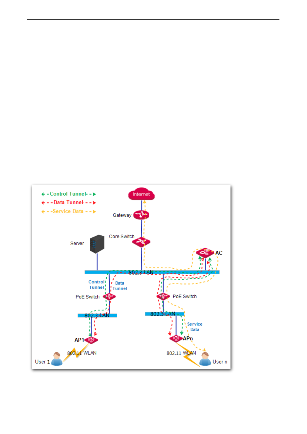
Centralized Forwarding Mode
In this mode, AC and AP establish two tunnels: control tunnel and data tunnel.
In control tunnel, AC and AP communicate with each other by management packets and control packets. The AC
can control and deliver configurations to AP.
In data tunnel, AC and AP forward user’s service data. After a user connects to an AP’s SSID, the following
procedure occurs:
1. The AP converts 802.11 protocol packets to 802.3 protocol packets.
2. The AP encapsulates the 802.3 protocol packets.
3. The encapsulated packets are forwarded to the AC in the data tunnel.
4. The AC decapsulates the packets to 802.3 protocol packets.
5. The AC checks its own routing table and forwards the packets to its destination.
(The destination may be a host or a gateway.)
6. When the AC receives response packets from the destination, the AC will encapsulate the packets and
forward the packets to AP in the data tunnel.
-Page 21-
Page 25

Application of AP Forwarding Mode
Distributed Forwarding Mode
In this mode, AC and AP only establish one tunnel: control tunnel.
In control tunnel, AC and AP communicate with each other by management packets and control packets. The AC
can control and deliver configurations to AP.
After a user connects to an AP’s SSID, the following procedure occurs:
1. The AP converts 802.11 protocol packets to 802.3 protocol packets.
2. The AP checks FIB table of its own and forwards the packets to its destination.
(The destination may be a host or a gateway.)
In distributed forwarding mode, data packets will not get through AC so that AC can manage much more APs and
users, the maximum is 3000 APs and 50000 users.
Application Example
Scenario 1: ISP WLAN Network
In this scenario, the fit AP is always set to centralized forwarding mode. Because the ISP need to monitor each
user’s traffic usage.
-Page 22-
Page 26

Application of AP Forwarding Mode
Scenario 2: Enterprise Network
In this scenario, the fit AP is always set to distributed forwarding mode.
Scenario 3: Campus WLAN Network
In this scenario, it is recommended to use mixed forwarding mode. Some fit APs are set to centralized forwarding
mode to forward the Internet service data, and the other fit APs are set to distributed forwarding mode to
forward the internal service data.
4.2 Configuration Guide
Centralized Forwarding Mode
-Page 23-
Page 27

Application of AP Forwarding Mode
Distributed Forwarding Mode
4.3 Application Example
Centralized Forwarding Mode Application
Networking Requirement
An enterprise needs to establish a wireless network. For guests, the requirements are described below:
Guests connected to the WiFi can only access the Internet.
WiFi password is not required when the guests connect to the WiFi.
For network’s security, the enterprise needs to use AC to control guests’ traffic data, so the SSID for guests
should be set to centralized forwarding mode.
-Page 24-
Page 28

Network Topology
Application of AP Forwarding Mode
Assumption
By default, the AP has no management VLAN and is managed by the AC.
By default, all switches have enabled IEEE 802.1Q VLAN feature and all ports are in VLAN 1.
In this example, the SSID for guests is Internet.
In this example, the gateway is in VLAN 8 and provides a DHCP server, which can assign IP addresses for
guests.
-Page 25-
Page 29

Configuration Step
Configure AC
Application of AP Forwarding Mode
Step 1: Configure VLAN Interface
To configure VLAN interface:
1. Log in to AC’s Web UI and go to Network Setting > Network Setting > VLAN Interface Settings.
2. Click Add to create a VLAN interface. This VLAN interface is used by centralized forwarding mode.
VLAN Interface: Enter a name for the VLAN Interface. Here we enter Guest.
Physical Port: Select one or more physical ports belonging to the VLAN Interface. Here we select LAN1.
VLAN ID: Enter a VLAN ID for the VLAN interface. Here we enter 8.
Click Save to apply your settings.
-Page 26-
Page 30

Application of AP Forwarding Mode
Step 2: Configure SSID Policy
To Configure SSID Policy:
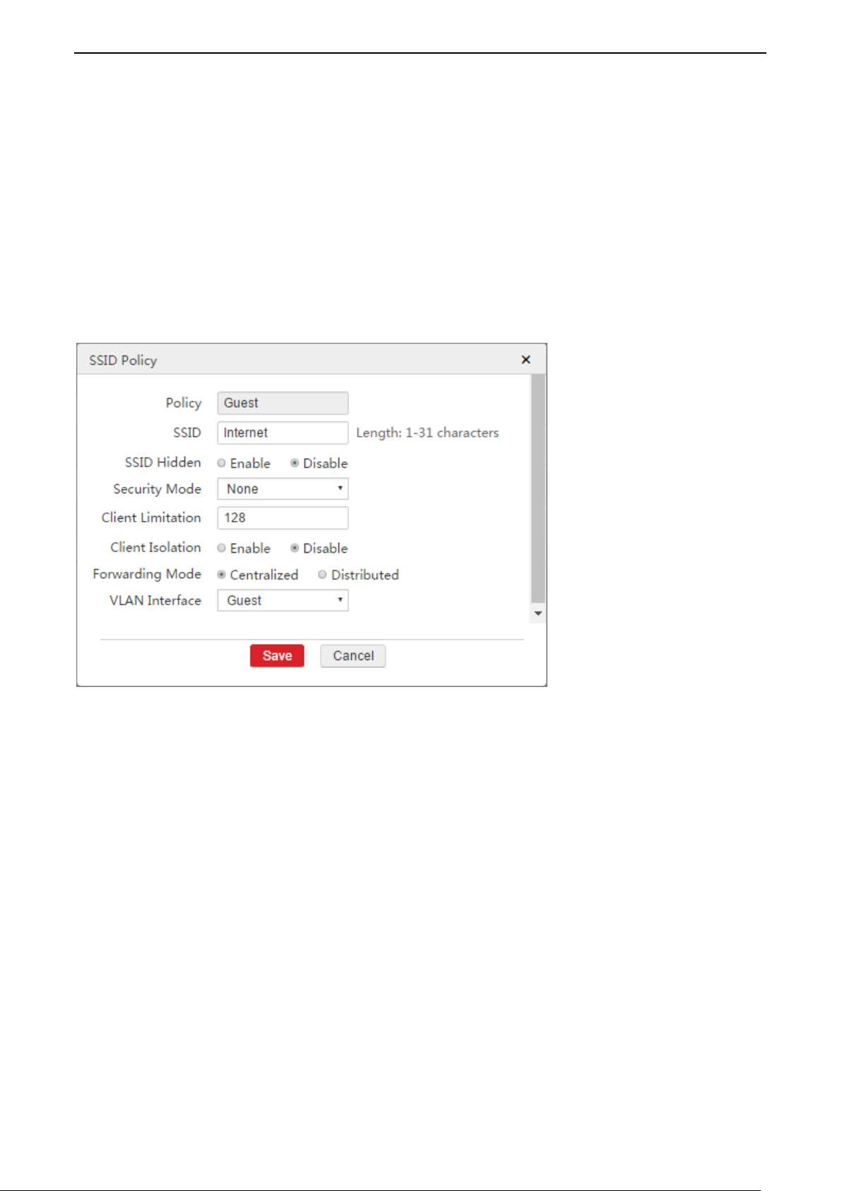
1. Log in to AC’s Web UI and go to Policy Management > SSID Policy.
2. Click Add to create a SSID policy.
Policy: Enter a policy name for the SSID policy. Here we enter Guest.
SSID: Enter a SSID name for guests. Here we enter Internet.
Forwarding Mode: Select Centralized.
VLAN Interface: Select Guest.
Click Save to apply your settings.
Step 3: Configure SSID Group
For better management of SSID-related policies (such as SSID policy, SSID Scheduler, MAC Filter, and so on), add
all the SSID-related policies into a SSID group. In this way, you don’t need to deliver policies one by one. Besides,
you can add several SSID policies into one SSID group and all the added SSID policies will be delivered to APs.
To Configure SSID group:
1. Log in to AC’s Web UI and go to AP Management > SSID Group.
2. Click Add to create a SSID group. The SSID group is used to contain the above SSID policy and will be used by
AP group.
SSID Group: Enter a SSID group name. Here we enter Enterprise.
Remark: Enter a remark for the SSID policy. Here we enter Guest.
SSID Policy: Select a SSID Policy. Here we select Guest.
Click Save to apply your settings.
-Page 27-
Page 31

Application of AP Forwarding Mode
Step 4: Configure AP Group
For better management of all policies (including SSID group, RF policy, RF Optimization, AP Maintain, and so on),
add the policies into an AP group. In this way, you can deliver an AP group to APs instead of delivering policies
one by one.
To Configure AP group:
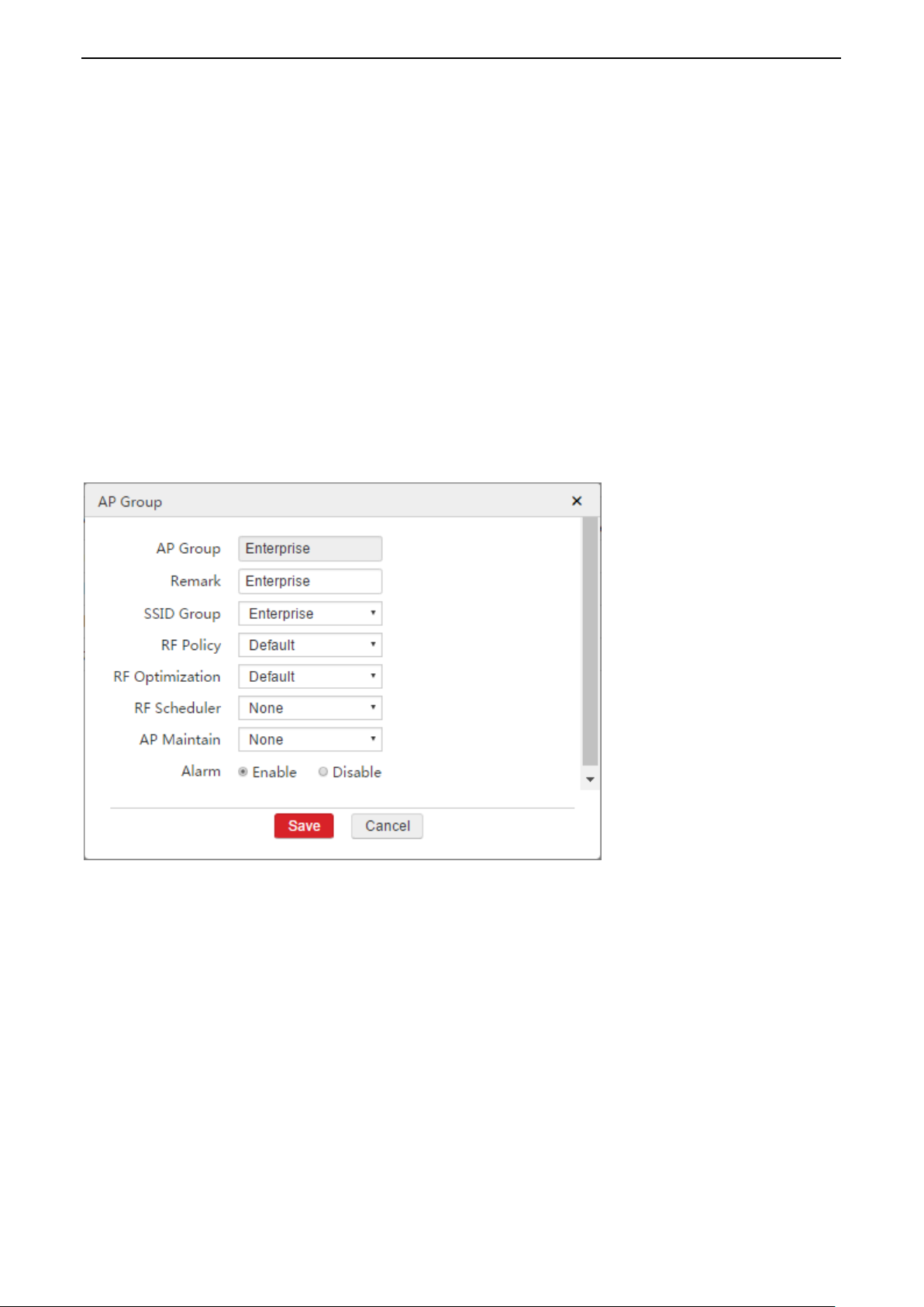
1. Log in to AC’s Web UI and go to AP Management > AP Group.
2. Click Add to create an AP group. This AP group is used to contain above SSID group and a RF policy, and will be
delivered to APs.
AP Group: Enter a name for the AP group. Here we enter Enterprise.
Remark: Enter a remark for the AP group. Here we enter Enterprise.
SSID Group: Select a SSID group. Here we select Enterprise.
RF Policy: Select a RF policy. Here we take the default RF policy as an example.
Click Save to apply your settings.
-Page 28-
Page 32

Application of AP Forwarding Mode
The port connects to
VLAN ID
Port Mode
PVID
PoE Switch
1
Access
1
AC
1,8
Trunk
1
Gateway
8
Access
8
Step 5: Deliver AP Group to APs
To Deliver AP Group to APs:
1. Log in to AC’s Web UI and go to AP Management > Modify AP.
2. Select all APs.
3. Click Batch Group.
4. In the pop-up window, select Enterprise.
5. Click Save.
Then APs will get all configurations in the AP group.
The selected APs may reboot to make the settings take effect. Please wait for 1~2 minutes, then the APs will get
online automatically and you can see that the new AP group has been delivered to these APs.
Configure Core Switch
Set up the switch’s VLAN value. The corresponding port is set as follows:
Please keep other ports’ VLAN value default. For configuration details, refer to the switch’s user guide.
Configure PoE Switch
No configuration is required for PoE switch. Because in this example, we use centralized forwarding mode, the AP
will encapsulate user packets so that intermediate devices don’t need to deal with the VLAN data.
Verify the Configuration
After guests connect to the SSID Internet successfully, they can surf the Internet but can’t access the enterprise’s
server.
-Page 29-
Page 33

Application of AP Forwarding Mode
Distributed Forwarding Mode Application
Networking Requirement
An enterprise needs to establish a wireless network. For employees, the requirements are described below:
Employees can only access the enterprise’s server.
The wireless network is encrypted with WPA2-PSK/AES security mode.
To save network bandwidth, the SSID for employees is set to distributed forwarding mode.
Network Topology
Assumption
By default, the AP has no management VLAN and is managed by the AC.
By default, all switches have enabled IEEE 802.1Q VLAN feature and all ports are in VLAN 1.
In this example, the SSID for employees is Internal.
In this example, the server is in VLAN 5 and provides a DHCP server, which can assign IP address for
employees.
-Page 30-
Page 34

Configuration Step
Configure AC
Application of AP Forwarding Mode
Step 1: Configure SSID Policy
To Configure SSID Policy:
1. Log in to AC’s Web UI and go to Policy Management > SSID Policy.
2. Click Add to create a SSID policy.
Policy: Enter a policy name for the SSID policy. Here we enter Employee.
SSID: Enter a SSID name for employees. Here we enter Internal.
Security Mode: Select WPA2-PSK.
Encryption: Select AES.
Password: Enter a password, such as 87654321.
Forwarding Mode: Select Distributed.
VLAN ID: Enter 5.
Click Save to apply your settings.
-Page 31-
Page 35

Application of AP Forwarding Mode
Step 2: Configure SSID Group
For better management of SSID-related policies (such as SSID policy, SSID Scheduler, MAC Filter, and so on), add
all the SSID-related policies into a SSID group. In this way, you don’t need to deliver policies one by one. Besides,
you can add several SSID policies into one SSID group and all the added SSID policies will be delivered to APs.
To Configure SSID group:
1. Log in to AC’s Web UI and go to AP Management > SSID Group.
2. Click Add to create a SSID group. The SSID group is used to contain the above SSID policy and will be used by
AP group.
SSID Group: Enter a SSID group name. Here we enter Enterprise.
Remark: Enter a remark for the SSID policy. Here we enter Employee.
SSID Policy: Select a SSID Policy. Here we select Employee.
Click Save to apply your settings.
-Page 32-
Page 36
Application of AP Forwarding Mode
Step 3: Configure AP Group
For better management of all policies (including SSID group, RF policy, RF Optimization, AP Maintain, and so on),
add the policies into an AP group. In this way, you can deliver an AP group to APs instead of delivering policies
one by one.
To Configure AP group:
1. Log in to AC’s Web UI and go to AP Management > AP Group.
2. Click Add to create an AP group. This AP group is used to contain above SSID group and a RF policy, and will be
delivered to APs.
AP Group: Enter a name for the AP group. Here we enter Enterprise.
Remark: Enter a remark for the AP group. Here we enter Enterprise.
SSID Group: Select a SSID group. Here we select Enterprise.
RF Policy: Select a RF policy. Here we take the default RF policy as an example.
Click Save to apply your settings.
Step 4: Deliver AP Group to APs
To Deliver AP Group to APs:
1. Log in to AC’s Web UI and go to AP Management > Modify AP.
2. Select all APs.
3. Click Batch Group.
4. In the pop-up window, select Enterprise.
5. Click Save.
Then APs will get all configurations in the AP group.
The selected APs may reboot to make the settings take effect. Please wait for 1~2 minutes, then the APs will get
online automatically and you can see that the new AP group has been delivered to these APs.
-Page 33-
Page 37

Application of AP Forwarding Mode
The port connects to
VLAN ID
Port Mode
PVID
PoE Switch
1,5
Trunk
1
AC 1 Access
1
Server
5
Access
5
The port connects to
VLAN ID
Port Mode
PVID
Core Switch
1,5
Trunk
1
AP
1,5
Trunk
1
Configure Core Switch
Set up the switch’s VLAN value. The corresponding port is set as follows:
Please keep other ports’ VLAN value default. For configuration details, refer to the switch’s user guide
Configure PoE Switch
Set up the switch’s VLAN value. The corresponding port is set as follows:
Please keep other ports’ VLAN value default. For configuration details, refer to the switch’s user guide
Verify the Configuration
After employees connect to the SSID Internal successfully, they can access the server but can’t surf the Internet.
-Page 34-
Page 38

Application of AP Forwarding Mode
Mixed Forwarding Mode Application 1
Networking Requirement
An enterprise needs to establish a wireless network.
For guests, the requirements are described below:
Guests connected to the WiFi can only access the Internet.
WiFi password is not required when the guests connect to the WiFi.
For network’s security, the enterprise needs to use AC to control guests’ traffic data, so the SSID for guests
should be set to centralized forwarding mode.
For employees, the requirements are described below:
Employees can only access the enterprise’s server.
The wireless network is encrypted with WPA2-PSK/AES security mode.
To save network bandwidth, the SSID for employees is set to distributed forwarding mode.
Network Topology
-Page 35-
Page 39

Application of AP Forwarding Mode
Assumption
The AP works at 2.4G band. By default, the AP has no management VLAN and is managed by the AC.
By default, all switches have enabled IEEE 802.1Q VLAN feature and all ports are in VLAN 1.In this example,
the SSID for guests is Internet.
In this example, the gateway is in VLAN 8 and provides a DHCP server, which can assign IP addresses for
guests.
In this example, the server is in VLAN 5 and is a DNS proxy.
In this example, employee’s IP address is assigned by AC.
In this example, the SSID for guests is Internet.
In this example, the SSID for employees is Internal.
Configuration Step
Configure AC
-Page 36-
Page 40

Application of AP Forwarding Mode
Step 1: Configure VLAN Interface
To configure VLAN interface:
1. Log in to AC’s Web UI and go to Network Setting > Network Setting > VLAN Interface Settings.
2. Click Add to create a VLAN interface. This VLAN interface is used by centralized forwarding mode.
VLAN Interface: Enter a name for the VLAN Interface. Here we enter Guest.
Physical Port: Select one or more physical ports belonging to the VLAN Interface. Here we select LAN1.
VLAN ID: Enter a VLAN ID for the VLAN interface. Here we enter 8.
Click Save to apply your settings.
3. Click Add to create another VLAN interface. This VLAN interface is used to create a DHCP server for employees.
VLAN Interface: Enter the name for the VLAN Interface. Here we enter Employee.
Physical Port: Select one or more physical ports belonging to the VLAN Interface. Here we select LAN1.
VLAN ID: Enter a VLAN ID for the VLAN interface. Here we enter 5.
Click Save to apply your settings.
-Page 37-
Page 41

Application of AP Forwarding Mode
Step 2: Configure IP and DHCP Server Settings
In this example, employees obtain IP addresses from AC so that we need to create a DHCP server for employees.
To Configure IP and DHCP Server Settings:
1. Log in to AC’s Web UI and go to Network Setting > Network Setting > IP and DHCP Server Settings.
2. Click Add to create an IP address and a DHCP server.
VLAN Interface: Select Employee.
IP Address: Enter an IP address on the same IP segment with server’s IP address. Here we enter
192.168.1.10.
Subnet Mask: Enter the server’s subnet mask. Here we enter 255.255.255.0.
DHCP Server: Select Enable.
Assign IP to: Select User.
Remark: Enter a remark for this DHCP server. Here we enter Employee.
Gateway: Enter a gateway which will be assigned to employees. Here we enter the server’s IP address:
192.168.1.1.
Primary DNS: Enter a DNS address which will be assigned to employees. Here we enter the server’s IP
address: 192.168.1.1.
Start IP: Enter a start IP of the DHCP server, such as 192.168.1.100.
End IP: Enter an end IP of the DHCP server, such as 192.168.1.200.
Make sure that the amount of IP is more than the amount of employee.
Click Save to apply your settings.
-Page 38-
Page 42
Application of AP Forwarding Mode
Step 3: Configure SSID Policy
To Configure SSID Policy:
1. Log in to AC’s Web UI and go to Policy Management > SSID Policy.
2. Click Add to create a SSID policy.
Policy: Enter a policy name for the SSID policy. Here we enter Guest.
SSID: Enter a SSID name for guests. Here we enter Internet.
Forwarding Mode: Select Centralized.
VLAN Interface: Select Guest.
Click Save to apply your settings.
3. Click Add to create another SSID policy.
Policy: Enter a policy name for the SSID policy. Here we enter Employee.
SSID: Enter a SSID name for employees. Here we enter Internal.
Security Mode: Select WPA2-PSK.
Encryption: Select AES.
Password: Enter a password, such as 87654321.
Forwarding Mode: Select Distributed.
VLAN ID: Enter 5.
Click Save to apply your settings.
-Page 39-
Page 43

Application of AP Forwarding Mode
Step 4: Configure SSID Group
For better management of SSID-related policies (such as SSID policy, SSID Scheduler, MAC Filter, and so on), add
all the SSID-related policies into a SSID group. In this way, you don’t need to deliver policies one by one. Besides,
you can add several SSID policies into one SSID group and all the added SSID policies will be delivered to APs.
To Configure SSID group:
1. Log in to AC’s Web UI and go to AP Management > SSID Group.
2. Click Add to create a SSID group. The SSID group is used to contain the above SSID policy and will be used by
AP group.
SSID Group: Enter a SSID group name. Here we enter Enterprise.
Add the SSID policy Guest to this SSID group.
Radio: Select a radio band. Here we select 2.4G.
Remark: Enter a remark for the SSID policy of Guest. Here we enter Guest.
SSID Policy: Select Guest.
Click to add the other SSID policy.
Radio: Select 2.4G.
Remark: Enter a remark for the SSID policy of Employee. Here we enter Employee.
SSID Policy: Select Employee.
Click Save to apply your settings.
-Page 40-
Page 44

Application of AP Forwarding Mode
Step 5: Configure AP Group
For better management of all policies (including SSID group, RF policy, RF Optimization, AP Maintain, and so on),
add the policies into an AP group. In this way, you can deliver an AP group to APs instead of delivering policies
one by one.
To Configure AP group:
1. Log in to AC’s Web UI and go to AP Management > AP Group.
2. Click Add to create an AP group. This AP group is used to contain above SSID group and a RF policy, and will be
delivered to APs.
AP Group: Enter a name for the AP group. Here we enter Enterprise.
Remark: Enter a remark for the AP group. Here we enter Enterprise.
SSID Group: Select a SSID group. Here we select Enterprise.
RF Policy: Select a RF policy. Here we take the default RF policy as an example.
Click Save to apply your settings.
-Page 41-
Page 45

Application of AP Forwarding Mode
The port connects to
VLAN ID
Port Mode
PVID
PoE Switch
1,5
Trunk
1
AC
1,5,8
Trunk
1
Server
5
Access
5
Gateway
8
Access
8
The port connects to
VLAN ID
Port Mode
PVID
Core Switch
1,5
Trunk
1
AP
1,5
Trunk
1
Step 6: Deliver AP Group to APs
To Deliver AP Group to APs:
1. Log in to AC’s Web UI and go to AP Management > Modify AP.
2. Select all APs.
3. Click Batch Group.
4. In the pop-up window, select Enterprise.
5. Click Save.
Then APs will get all configurations in the AP group.
The selected APs may reboot to make the settings take effect. Please wait for 1~2 minutes, then the APs will get
online automatically and you can see that the new AP group has been delivered to these APs.
Configure Core Switch
Set up the switch’s VLAN value. The corresponding port is set as follows:
Please keep other ports’ VLAN value default. For configuration details, refer to the switch’s user guide
Configure PoE Switch
Set up the switch’s VLAN value. The corresponding port is set as follows:
Please keep other ports’ VLAN value default. For configuration details, refer to the switch’s user guide
-Page 42-
Page 46

Application of AP Forwarding Mode
Verify the Configuration
After guests connect to the SSID Internet successfully, they can surf the Internet but can’t access the enterprise’s
server.
After employees connect to the SSID Internal successfully, they can access the server but can’t surf the Internet.
-Page 43-
Page 47

Application of AP Forwarding Mode
Mixed Forwarding Mode Application 2
A hotel needs to establish a wireless network. The hotel has purchased the following devices:
A gateway
A core switch and several PoE switches
A server
An IP-COM AC3000
Several IP-COM fit APs
Among them, the gateway and server don’t support IEEE 802.1Q VLAN but both have a build-in DHCP server
which can assign IP address for user. The PoE switch supports IEEE 802.1Q VLAN.
Networking Requirement
There are three types of user: Employee, Guest and Manager. Any two types of user can’t communicate with
each other. The requirements are described below:
Employees only have permission to access internal server. The SSID for employees is Internal and use
WPA2-PSK/AES security encryption.
Guests can only surf the Internet. The SSID for guests is Internet and use no security encryption.
Managers have both the permission to access internal server and to surf the Internet. The SSID for managers
is VIP and use WPA2-PSK/AES security encryption.
-Page 44-
Page 48

Network Topology
Application of AP Forwarding Mode
Assumption
By default, the connected ports of all switches are in VLAN 1 and the port mode is access.
The DNS server address used to surf the Internet is 8.8.8.8.
APs obtain IP address on IP setment 192.168.80.0/24 from AC.
Managers obtain IP address on IP setment 192.168.30.0/24 from AC.
Other assumptions are shown on the network topology.
-Page 45-
Page 49

Application of AP Forwarding Mode
Configuration Step
Configure AC
Step 1: Configure VLAN Interface
In order to manage AP, communicate with internal server, communicate with gateway, and be used for
centralized forwarding by the manager’s SSID, you need to add four VLAN interfaces respectively.
To Configure VLAN Interface:
1. Log in to AC’s Web UI and go to Network Setting > Network Setting > VLAN Interface Settings.
2. Click Add to create a VLAN interface. This VLAN interface is used to manage AP.
VLAN Interface: Enter Manage_AP.
Physical Port: Select LAN1.
If LAN1 port has been in VLAN 0, it is recommended to remove LAN1 port from this VLAN interface first.
VLAN ID: Enter 0.
Click Save to apply your settings.
3. Click Add to create a VLAN interface. This VLAN interface is used to communicate with the internal server.
VLAN Interface: Enter Server.
Physical Port: Select LAN1.
VLAN ID: Enter 10.
Click Save to apply your settings.
-Page 46-
Page 50

Application of AP Forwarding Mode
4. Click Add to create a VLAN interface. This VLAN interface is used to communicate with the gateway.
VLAN Interface: Enter Gateway.
Physical Port: Select LAN1.
VLAN ID: Enter 20.
Click Save to apply your settings.
5. Click Add to create a VLAN interface. This VLAN interface is used for centralized forwarding by the manager’s
SSID.
VLAN Interface: Enter Manager.
Physical Port: Select LAN1.
VLAN ID: Enter 30.
Click Save to apply your settings.
-Page 47-
Page 51

Application of AP Forwarding Mode
Step 2: Configure IP and DHCP Server Settings
In this example, we need to create four IP and DHCP server settings:
One is to communicate with AP and assign IP address to AP.
One is to communicate with internal server.
One is to communicate with gateway.
One is to communicate with manager and assign IP address to manager.
To Configure IP and DHCP Server Settings:
1. Log in to AC’s Web UI and go to Network Setting > Network Setting > IP and DHCP Server Settings.
2. Click Add to create an IP and DHCP Server rule. This rule is used to communicate with AP and assign IP
address to AP.
VLAN Interface: Select Manage_AP.
IP Address: Enter an IP address. Here we enter 192.168.80.1.
Subnet Mask: Enter a subnet mask. Here we enter 255.255.255.0.
DHCP Server: Select Enable.
Assign IP to: Select AP.
Remark: Enter a remark for this DHCP server, such as Manage_AP.
Primary DNS: Enter a DNS address which will be assigned to AP, such as 8.8.8.8.
Start IP: Enter a start IP of the DHCP server, such as 192.168.80.100.
End IP: Enter an end IP of the DHCP server, such as 192.168.80.200.
Make sure that the amount of IP is more than the amount of AP.
Click Save to apply your settings.
-Page 48-
Page 52

Application of AP Forwarding Mode
3. Click Add to create an IP and DHCP Server rule. This rule is used to communicate with internal server.
VLAN Interface: Select Server.
IP Address: Enter an IP address on the same IP segment with server’s IP address. Here we enter
192.168.110.2.
Subnet Mask: Enter a subnet mask which should be the same with server’s subnet mask. Here we enter
255.255.255.0.
Click Save to apply your settings.
-Page 49-
Page 53

Application of AP Forwarding Mode
4. Click Add to create an IP and DHCP Server rule. This rule is used to communicate with gateway.
VLAN Interface: Select Gateway.
IP Address: Enter an IP address on the same IP segment of gateway’s LAN IP address. Here we enter
192.168.20.2.
Subnet Mask: Enter a subnet mask which should be the same with gateway’s subnet mask. Here we
enter 255.255.255.0.
Click Save to apply your settings.
5. Click Add to create an IP and DHCP Server rule. This rule is used to communicate with manager and assign IP
address to manager.
VLAN Interface: Select Manager.
IP Address: Enter an IP address. Here we enter 192.168.30.1.
Subnet Mask: Enter a subnet mask. Here we enter 255.255.255.0.
DHCP Server: Select Enable.
Assign IP to: Select User.
Remark: Enter a remark for this DHCP server, such as Manager.
Gateway: Enter a gateway. In this example, we enter this interfaces’s IP address: 192.168.30.1.
Primary DNS: Enter a DNS address which will be assigned to manager. In this example, we enter 8.8.8.8.
Start IP: Enter a start IP of the DHCP server, such as 192.168.30.100.
End IP: Enter an end IP of the DHCP server, such as 192.168.30.120.
Make sure that the amount of IP is more than the amount of manager.
Click Save to apply your settings.
Step 3: Configure Internet Settings for AC
In this example, managers surf the Internet through the AC, so we need to add a default route for the AC to
access the Internet.
To Configure Internet Settings for AC:
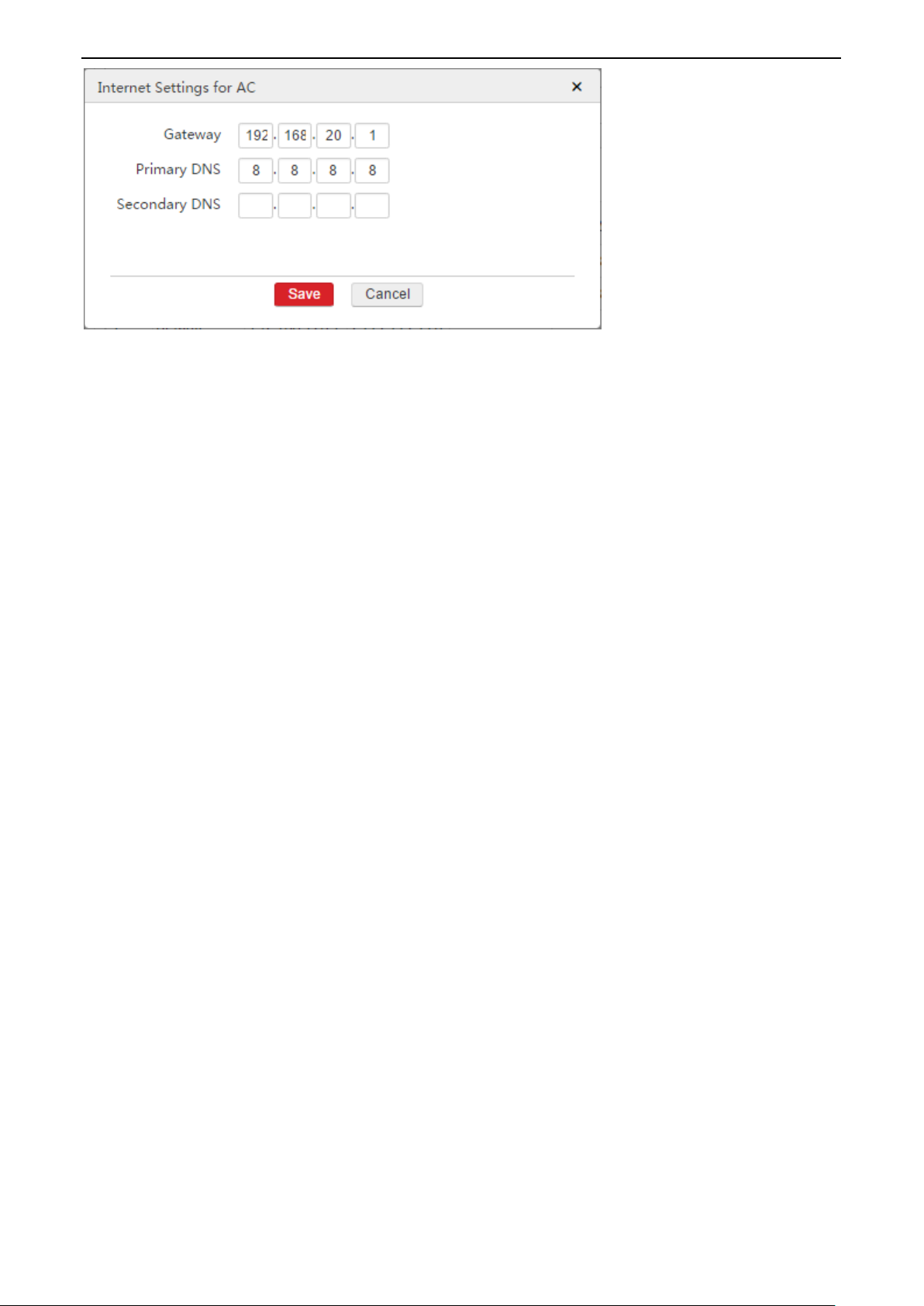
1. Log in to AC’s Web UI and go to Network Setting > Network Setting > Internet Settings for AC.
2. Click Add to create a default route for the AC.
Gateway: Enter the next hop’s IP address. Here we enter the gateway’s LAN IP address: 192.168.20.1.
Primary DNS: Enter a DNS server address. Here we enter 8.8.8.8.
Click Save to apply your settings.
-Page 50-
Page 54
Application of AP Forwarding Mode
After finishing the above configuration, you can go to Network Setting > IP Routing to view the default IP route.
Step 4: Configure SSID Policy
In this example, we need to create three SSID policies:
One SSID is for employees.
One SSID is for guests.
One SSID is for managers.
To Configure SSID Policy:
1. Log in to AC’s Web UI and go to Policy Management > SSID Policy.
2. Click Add to create a SSID policy. The SSID in this policy is for employees.
Policy: Enter a policy name for the SSID policy. Here we enter Employee.
SSID: Enter a SSID name. Here we enter Internal.
Security Mode: Select WPA2-PSK.
Encryption: Select AES.
Password: Enter a password, such as 87654321.
Forwarding Mode: Select Distributed.
VLAN ID: Enter 10.
Click Save to apply your settings.
-Page 51-
Page 55

Application of AP Forwarding Mode
3. Click Add to create a SSID policy. The SSID in this policy is for guests.
Policy: Enter a policy name for the SSID policy. Here we enter Guest.
SSID: Enter a SSID name. Here we enter Internet.
Forwarding Mode: Select Distributed.
VLAN ID: Enter 20.
Click Save to apply your settings.
-Page 52-
Page 56

Application of AP Forwarding Mode
4. Click Add to create a SSID policy. The SSID in this policy is for managers.
Policy: Enter a policy name for the SSID policy. Here we enter Manager.
SSID: Enter a SSID name. Here we enter VIP.
Security Mode: Select WPA2-PSK.
Encryption: Select AES.
Password: Enter a password, such as 1234567890.
Forwarding Mode: Select Centralized.
VLAN Interface: Select Manager.
Click Save to apply your settings.
Step 5: Configure SSID Group
For better management of SSID-related policies (such as SSID policy, SSID Scheduler, MAC Filter, and so on), add
all the SSID-related policies into a SSID group. In this way, you don’t need to deliver policies one by one. Besides,
you can add several SSID policies into one SSID group and all the added SSID policies will be delivered to APs.
To Configure SSID group:
1. Log in to AC’s Web UI and go to AP Management > SSID Group.
2. Click Add to create a SSID group. The SSID group is used to contain the above SSID policy and will be used by
AP group.
SSID Group: Enter a SSID group name. Here we enter Enterprise.
Add the SSID policy Employee to this SSID group.
Remark: Enter a remark for the SSID policy of Employee. Here we enter Employee.
SSID Policy: Select Employee.
Click to add the SSID policy Guest to this SSID group.
Remark: Enter a remark for the SSID policy of Guest. Here we enter Guest.
SSID Policy: Select Guest.
Click to add the SSID policy Manager to this SSID group.
Remark: Enter a remark for the SSID policy of Manager. Here we enter Manager.
SSID Policy: Select Manager.
Click Save to apply your settings.
-Page 53-
Page 57

Application of AP Forwarding Mode
Step 6: Configure AP Group
For better management of all policies (including SSID group, RF policy, RF Optimization, AP Maintain, and so on),
add the policies into an AP group. In this way, you can deliver an AP group to APs instead of delivering policies
one by one.
To Configure AP group:
1. Log in to AC’s Web UI and go to AP Management > AP Group.
2. Click Add to create an AP group. This AP group is used to contain above SSID group and a RF policy, and will be
delivered to APs.
AP Group: Enter a name for the AP group. Here we enter Enterprise.
Remark: Enter a remark for the AP group. Here we enter Enterprise.
SSID Group: Select a SSID group. Here we select Enterprise.
RF Policy: Select a RF policy. Here we take the default RF policy as an example.
Click Save to apply your settings.
-Page 54-
Page 58

Application of AP Forwarding Mode
The port connects to
VLAN ID
Port Mode
PVID
PoE Switch
1,10,20
Trunk
1
AC
1,10,20
Trunk
1
Server
10
Access
10
Gateway
20
Access
20
The port connects to
VLAN ID
Port Mode
PVID
Core Switch
1,10,20
Trunk
1
AP
1,10,20
Trunk
1
Step 7: Deliver AP Group to APs
To Deliver AP Group to APs:
1. Log in to AC’s Web UI and go to AP Management > Modify AP.
2. Select all APs.
3. Click Batch Group.
4. In the pop-up window, select Enterprise.
5. Click Save.
Then APs will get all configurations in the AP group.
The selected APs may reboot to make the settings take effect. Please wait for 1~2 minutes, then the APs will get
online automatically and you can see that the new AP group has been delivered to these APs.
Configure Core Switch
Set up the switch’s VLAN value. The corresponding port is set as follows:
Please keep other ports’ VLAN value default. For configuration details, refer to the switch’s user guide
Configure PoE Switch
Set up the switch’s VLAN value. The corresponding port is set as follows:
Please keep other ports’ VLAN value default. For configuration details, refer to the switch’s user guide
-Page 55-
Page 59

Application of AP Forwarding Mode
Configure Gateway
Tip
The following configuration is just a guideline. For configuration details, please refer to the device’s user guide.
Step 1: Configure NAT
On the gateway’s Web UI, create a NAT rule to ensure that managers can surf the Internet.
The rule description is as follows:
IP address: Enter the IP segment of managers. In this example, we enter 192.168.30.0/24.
Interface: Select the gateway’s interface which connects to the Internet.
Step 2: Configure IP routing
On the gateway’s Web UI, create an IP route to ensure that the gateway is reachable to the managers’ network.
The rule description is as follows:
Destination Network: Enter the IP segment of managers. In this example, we enter 192.168.30.0/24.
Gateway: Enter a gateway to reach destination network. In this example, we enter the AC’s IP address on the
Gateway interface, the IP address is 192.168.20.2.
Interface: Select the interface which connects to core switch.
Step 3: Configure DHCP Server
On the gateway’s Web UI, enable DHCP server to assign IP address to guests.
The DHCP server is configured as follows:
DHCP server’s start IP and end IP: Both are on the IP segment 192.168.20.0/24.
Gateway: Enter the gateway’s LAN IP address 192.168.20.1.
Primary DNS: In this example, enter 8.8.8.8.
Configure Server
Tip
The following configuration is just a guideline. For configuration details, please refer to the device’s user guide.
Step 1: Configure IP routing
On the server’s Web UI, create an IP route to ensure that the server is reachable to the managers’ network.
The rule description is as follows:
Destination Network: Enter the IP segment of managers. In this example, we enter 192.168.30.0/24.
Gateway: Enter a gateway to reach destination network. In this example, we enter the AC’s IP address on the
Server interface, the IP address is 192.168.110.2.
Interface: Select the interface which connects to core switch.
-Page 56-
Page 60

Application of AP Forwarding Mode
Step 2: Configure DHCP Server
On the server’s Web UI, enable DHCP server to assign IP address to employees.
The DHCP server is configured as follows:
DHCP server’s start IP and end IP: Both are on the IP segment 192.168.110.0/24.
Gateway: Enter the server’s LAN IP address 192.168.110.1.
Primary DNS: In this example, enter 192.168.110.1.
Verify the Configuration
If you connect to the SSID Internal, you will obtain an IP address from the IP segment 192.168.110.0/24 and can
only access the server.
If you connect to the SSID Internet, you will obtain an IP address from the IP segment 192.168.20.0/24 and can
only surf the Internet.
If you connect to the SSID VIP, you will obtain an IP address from the IP segment 192.168.30.0/24 and can access
the server and surf the Internet at the same time.
-Page 57-
Page 61

Application of Network Settings
Part 5 Application of Network Settings
By configuring network settings, you can:
Manage cross-VLAN APs and users by creating multiple VLAN interfaces.
Communicate with other devices by setting up IP address on appropriate VLAN interfaces.
Assign IP address to AP or user by enabling DHCP server on appropriate VLAN interfaces.
Make the AC access Internet by setting up Internet parameters.
Make the AC reach different destination networks by setting up different IP routing rules.
This part shows how to configure network settings through an example.
Networking Requirement
In this example, each device is divided into a certain VLAN network.
Networking Requirement is as follows.
Router 1 is in VLAN 3 and Router 2 is in VLAN 4.
All fit APs’ management VLAN is VLAN 5.
All users are in VLAN 6 and can access the Internet and server at the same time.
-Page 58-
Page 62

Network Topology
Application of Network Settings
Assumption
By default, AC’s LAN1 port is in VLAN 0 and AC’s IP address is 192.168.10.1.
By default, Administrator can manage AC with a manually configured IP address 192.168.10.X/24 (X is
between 2~254).
Router 2 is a DNS proxy.
All APs and users obtain IP address from AC.
Other assumptions are shown on the network topology.
-Page 59-
Page 63

Configuration Step
Application of Network Settings
Manage AP in VLAN 5
To Manage AP in VLAN 5:
1. Restore all APs to factory default.
Wait for 2~3 minutes, all APs will be managed by AC.
2. Configure AP’s “Management VLAN”.
1) Log in to AC’s Web UI and go to AP Management > Modify AP.
2) Select all APs and click Advanced Setting.
3) Set up “Management VLAN” to 5 and click Save.
4) Select all APs and click Reboot to make this configuration take effect.
3. Configure VLAN Interface.
1) Log in to AC’s Web UI and go to Network Setting > Network Setting > VLAN Interface Settings.
2) Click Add to create a VLAN setting.
-Page 60-
VLAN Interface: Enter a name for the VLAN Interface. Here we enter Manage_AP.
Physical Port: Select one or more physical ports belonging to the VLAN Interface. Here we select
LAN1.
VLAN ID: Enter a VLAN ID for the VLAN Interface. Here we enter 5.
Click Save to apply your settings.
Page 64

Application of Network Settings
4. Configure IP and DHCP Server Settings.
1) Log in to AC’s Web UI and go to Network Setting > Network Setting > IP and DHCP Server Settings.
2) Click Add to create an IP and DHCP setting as follows.
VLAN Interface: In this example, select Manage_AP.
IP Address: In this example, enter 192.168.5.1.
DHCP Server: Select Enable.
Assign IP to: Select AP.
Remark: Enter a name for this setting, such as Manage_AP.
Primary DNS: Enter a valid DNS address. In this example, enter 192.168.4.100.
Note: AC3000 is not a DNS proxy. Please enter an effective DNS address.
Start IP: Enter a start IP address, such as 192.168.5.100.
End IP: Enter a end IP address, such as 192.168.5.200.
-Page 61-
Page 65

Application of Network Settings
Port No.
The port connects to
VLAN ID
Port Mode
PVID
3
AP
1,5
Trunk
1 5 AP
1,5
Trunk
1
6
AP
1,5
Trunk
1
24
AC
1,5
Trunk
1
VLAN Interface
Physical Port
VLAN ID
Manage_User
LAN1
6
VLAN Interface
IP Address
Assign IP to
Gateway
Primary DNS
IP Range
Manage_User
192.168.6.1/24
User
192.168.6.1
192.168.4.100
192.168.6.0/24
Policy/SSID
Security Mode
Password
Forwarding Mode
VLAN Interface
Manage_User
WPA2-PSK
********
Centralized
Manage_User
5. Set up the switch’s VLAN value. The corresponding port is set as follows:
After you finish above settings, the AC can manage all APs in VLAN 5.
Manage User in VLAN 6
To Manage User in VLAN 6, configure settings on the AC as follows.
To Manage User in VLAN 6:
1. Configure VLAN Interface.
1) Log in to AC’s Web UI and go to Network Setting > Network Setting > VLAN Interface Settings.
2) Click Add to create a VLAN setting as follows.
2. Configure IP and DHCP Server Settings.
1) Go to Network Setting > Network Setting > IP and DHCP Server Settings.
2) Click Add to create an IP and DHCP setting as follows.
Note: AC3000 is not a DNS proxy. Please enter an effective DNS address.
3. Configure SSID Policy
1) Go to Policy Management > SSID Policy.
2) Click Add to create a SSID policy as follows.
-Page 62-
Page 66

Application of Network Settings
SSID Group
SSID Policy
Other Parameters
Manage_User
Manage_User
Keep the default value.
AP Group
SSID Group
Other Parameters
Manage_User
Manage_User
Keep the default value.
The Configured Router
Destination Network
Gateway
Interface
Router 1
192.168.6.0/24
192.168.3.1
Port 1
Router 2
192.168.6.0/24
192.168.4.1
Port 1
The Configured Router
IP Address
Subnet Mask
Interface
Router 1
192.168.6.0
255.255.255.0
Port 2
Router 2
192.168.6.0
255.255.255.0
Port 2
4. Configure SSID Group
1) Go to AP Management > SSID Group.
2) Click Add to create a SSID group as follows.
5. Configure AP Group
1) Go to AP Management > AP Group.
2) Click Add to create an AP group as follows.
6. Deliver AP Group to APs
1) Go to AP Management > Modify AP.
2) Select all APs and click Batch Group.
3) In the pop-up window, select Manage_User and click Save.
After you finish above settings, wireless users can obtain IP addresses from AC. IP information is as follows.
IP address: 192.168.6.0/24
Gateway: 192.168.6.1
Primary DNS: 192.168.4.100
Configure Router
To Configure Router:
1. On each router, create a route to reach users’ network.
2. On each router, create a NAT rule to ensure that users can access the Internet and server at the same time.
Note: In this example, you need to purchase routers which support creating NAT rule.
-Page 63-
Page 67

Application of Network Settings
VLAN Interface
Physical Port
VLAN ID
Router 1
LAN1
3
Router 2
LAN1
4
VLAN Interface
IP Address
DHCP Server
Router 1
192.168.3.1/24
Disable
Router 2
192.168.4.1/24
Disable
Gateway
Primary DNS
192.168.4.100
192.168.4.100
Remark
Destination Network
Subnet Mask
Next Hop
VLAN Interface
Server
172.16.0.0
255.255.0.0
192.168.3.100
Router 1
Port No.
The port connects to
VLAN ID
Port Mode
PVID
1
Router 1
3
Access
3
4
Router 2
4
Access
4
24
AC
3,4
Trunk
1
Configure AC Route
To Configure AC Route:
1. Configure VLAN Interface
1) Log in to AC’s Web UI and go to Network Setting > Network Setting > VLAN Interface Settings.
2) Click Add to create two VLAN interfaces as follows.
2. Configure IP and DHCP Server Settings
1) Log in to AC’s Web UI and go to Network Setting > Network Setting > IP and DHCP Server Settings.
2) Click Add to create two IP and DHCP settings as follows.
3. Configure Internet Settings for AC
1) Log in to AC’s Web UI and go to Network Setting > Network Setting > Internet Settings for AC.
2) Click Add to create an Internet setting for AC.
4. Configure IP routing
1) Log in to AC’s Web UI and go to Network Setting > IP Routing.
2) Click Add to create a route as follows.
5. Set up the switch’s VLAN value. The corresponding port is set as follows:
-Page 64-
Page 68

Application of Network Settings
VLAN Interface
Physical Port
VLAN ID
IP Address
DHCP Pool
Gateway
Primary DNS
Manage_AP
LAN1
5
192.168.5.1
192.168.5.0/24
192.168.5.1
192.168.4.100
Manage_User
LAN1
6
192.168.6.1
192.168.6.0/24
192.168.6.1
192.168.4.100
Router 1
LAN1
3
192.168.3.1
Disable DHCP
Router 2
LAN1
4
192.168.4.1
Disable DHCP
Remark
Destination Network
Subnet Mask
Next Hop
VLAN Interface
Status
Default
0.0.0.0
0.0.0.0
192.168.4.100
Router 2
Valid
Server
172.16.0.0
255.255.0.0
192.168.3.100
Router 1
Valid
SSID Name
SSID VLAN ID
Management VLAN ID
Manage_User
6
5
The Configured Router
Destination Network
Gateway
Interface
Router 1
192.168.6.0/24
192.168.3.1
Port 1
Router 2
192.168.6.0/24
192.168.4.1
Port 1
Verify the Configuration
After you finish all configurations above, both AC and users can access the Internet and server at the same time.
In Sum: All settings on Each Device
After finishing all configurations above, you can check corresponding settings on each device, shown as follows.
All Settings on AC
VLAN interface and IP/DHCP setttings:
IP Routes: (Go to Network Setting > IP Routing to check the following items.)
All Settings on AP (Delivered by AC)
All Settings on Router
IP Routes:
-Page 65-
Page 69

Application of Network Settings
The Configured Router
IP Address
Subnet Mask
Interface
Router 1
192.168.6.0
255.255.255.0
Port 2
Router 2
192.168.6.0
255.255.255.0
Port 2
Port No.
The port connects to
VLAN ID
Port Mode
PVID
1
Router 1
3
Access
3
2
Administrator
1
Access
1
3
AP
1,5
Trunk
1
4
Router 2
4
Access
4
5
AP
1,5
Trunk
1
6
AP
1,5
Trunk
1
24
AC3000
1,3,4,5
Trunk
1
NAT Rule:
All Settings on Switch
VLAN information on each port is configured as follows.
-Page 66-
Page 70

Application of Advertising
Part 6 Application of Advertising
By creating advertisements and deliver them to your customers, you can promote your products.
And to enhance wireless network’s security, you can set up authorization method for customers.
AC3000 English version supports three authorization methods: No Password, Portal and Facebook.
This part shows:
In No Password authorization, how to create and deliver advertisements.
In Portal authorization, how to create and deliver advertisements.
In Facebook authrization, how to create and deliver advertisements.
Besides, you can use these three authorization methods together. For example, on the same AP, you can deliver a
No Password advertisement to some SSIDs and deliver a Portal advertisement to rest SSIDs. Even for the same
SSID, you can deliver a No Password advertisement to some terminals and deliver a Portal advertisement to other
terminals, or you can deliver both portal and Facebook authorizations to the same SSID.
6.1 Application of No Password Authorization
Networking Requirement
A hotel needs to establish a wireless network and has the following expectations:
Guests in the hotel hall can surf the Internet with the wireless network.
Guests can see the advertisement about the hotel.
Guests don’t need to enter any password before they surf the Internet.
Assume that WiFi name is xx_hotel.
-Page 67-
Page 71

Network Topology
Application of Advertising
Configuration Step
Step 1: Create and deliver SSID to fit AP (Optional)
If you have delivered a SSID to fit AP, please directly skip to Step 2: Create Advertisement.
To Create and deliver SSID to fit AP:
1. Log in to AC’s Web UI and go to Policy Management > SSID Policy.
2. Click Add to create a SSID policy.
Policy: Enter xx_hotel.
SSID: Enter xx_hotel.
Click Save to apply your settings.
-Page 68-
Page 72

Application of Advertising
3. Go to AP Management > SSID Group and click Add to create a SSID group.
SSID Group: Enter xx_hotel.
Remark: Enter xx_hotel.
SSID Policy: Select xx_hotel.
Click Save to apply your settings.
4. Go to AP Management > AP Group and click Add to create a AP group.
AP Group: Enter xx_hotel.
Remark: Enter xx_hotel.
SSID Group: Select xx_hotel.
Click Save to apply your settings.
-Page 69-
Page 73

Application of Advertising
5. Go to AP Management > Modify AP, select all fit APs and click Batch Group.
Group: Select xx_hotel.
Click Save to apply your settings.
After finishing above settings, you can connect to SSID xx_hotel successfully.
Step 2: Create Advertisement
To Create Advertisement:
1. Log in to AC’s Web UI and go to Captive Portal > Create Ads > Create Ad.
2. Click Create Ad and configure the advertisement.
Select Template: Select Template 3. (Only Template 3 supports No Password authorization.)
-Page 70-
Page 74

Application of Advertising
Basic Info
Ad Name: Enter a name for this advertisement, such as xx_hotel.
Redirect Page: Enter a valid URL, such as www.google.com.
Users will be redirected to this page after they are authorized successfully.
Set Up Navigation: Click the navigation bar on the left and configure the navigation on the right.
Click Add Navigation to add a new navigation item.
Remark: Enter a name for the current navigation item.
Link: Enter a valid URL. Users will be redirected to the URL after they click this navigation item.
Click to save the current navigation item and click to edit the current navigation item.
Click to delete the current navigation item.
-Page 71-
Page 75

Application of Advertising
Set Up Slide Image: Click the image on the left and configure the image on the right.
Click Add Image to add a new slide image.
Remark: Enter a name for the current image.
Image: Upload an image.
Link: Enter a valid URL. Users will be redirected to the URL after they click this image.
Click to save the current image and click to edit the current image.
Click to delete the current image.
Click Save to apply your settings.
Step 3: Deliver Advertisement
To Deliver Advertisement:
1. Log in to AC’s Web UI and go to Captive Portal > Create Ads > Ad Push.
2. Click Add to deliver the above advertisement to terminals.
SSID Policy: Select xx_hotel.
Ad Name: In this example, select xx_hotel for corresponding terminals.
Click Save to apply your settings.
-Page 72-
Page 76

Application of Advertising
Verify the Configuration
After you connect to SSID xx_hotel and launch a browser, the xx_hotel advertisement will appear. Wait until the
countdown finishes, then click Click to Access Internet to surf the Internet.
6.2 Application of Portal Authorization
Networking Requirement
A hotel needs to establish a wireless network and has the following expectations:
Guests in a hotel room can surf the Internet with the wireless network.
These guests can see the advertisement about the hotel.
These guests need to enter portal account before they surf the Internet.
Assume that WiFi name is Room_606.
-Page 73-
Page 77

Network Topology
Application of Advertising
Configuration Step
Step 1: Create and deliver SSID to fit AP (Optional)
If you have delivered a SSID to fit AP, please directly skip to Step 2: Create Advertisement.
To Create and deliver SSID to fit AP:
1. Log in to AC’s Web UI and go to Policy Management > SSID Policy.
2. Click Add to create a SSID policy.
Policy: Enter Room_606.
SSID: Enter Room_606.
Click Save to apply your settings.
3. Go to AP Management > SSID Group and click Add to create a SSID group.
SSID Group: Enter Room_606.
Remark: Enter Room_606.
SSID Policy: Select Room_606.
Click Save to apply your settings.
4. Go to AP Management > AP Group and click Add to create an AP group.
AP Group: Enter Room_606.
Remark: Enter Room_606.
SSID Group: Select Room_606.
Click Save to apply your settings.
-Page 74-
Page 78

Application of Advertising
5. Go to AP Management > Modify AP, select fit APs and click Batch Group.
Group: Select Room_606.
Click Save to apply your settings.
After finishing above settings, you can connect to SSID Room_606 successfully.
Step 2: Create Advertisement
To Create Advertisement:
1. Log in to AC’s Web UI and go to Captive Portal > Create Ads > Create Ad.
2. Click Create Ad and configure the advertisement.
Select Template: Select Template 1 or Template 2.
(These two templates support Portal authorization.)
Basic Info
Ad Name: Enter a name for this advertisement, such as xx_hotel.
Redirect Page: Enter a valid URL, such as www.google.com.
Users will be redirected to this page after they are authorized successfully.
Set Up Logo: Click the left logo and upload a logo image for this Ad.
-Page 75-
Page 79

Application of Advertising
Set Up Navigation: Click the navigation bar on the left and configure the navigation on the right.
Click Add Navigation to add a new navigation item.
Remark: Enter a name for the current navigation item.
Link: Enter a valid URL. Users will be redirected to the URL after they click this navigation item.
Click to save the current navigation item and click to edit the current navigation item.
Click to delete the current navigation item.
Set Up Slide Image: Click the image on the left and configure the image on the right.
Click Add Image to add a new slide image.
Remark: Enter a name for the current image.
Image: Upload an image.
Link: Enter a valid URL. Users will be redirected to the URL after they click this image.
Click to save the current image and click to edit the current image.
Click to delete the current image.
-Page 76-
Page 80

Application of Advertising
Set up Authorization Method
(Template 1 and template 2 support Portal and Facebook authorizations.
Template 3 supports no password authorization.)
Slide down the mouse and click Other Methods.
On the pop-up page on the right, select Portal.
Click Save.
Set up copyright information: Click the left copyright information and enter new copyright information
on the right area.
-Page 77-
Page 81

Application of Advertising
Click Save to apply your settings.
Step 3: Create Portal Account
If you select Facebook authorization, please ignore this step.
To Create Portal Account:
1. Log in to AC’s Web UI and go to Captive Portal > Create Ads > Create Portal Account.
2. Click Add to create a Portal account.
Account: Enter an account name, such as Room_606.
Remark: Enter Room_606.
Password: Enter a password for this account.
Confirm Password: Enter the password again.
MAC Limit: It is recommended to select “Allow multiple users to authorize with the account” and enter
3.
Valid Period: It is recommended to select Permanently.
Click Save to apply your settings.
-Page 78-
Page 82

Application of Advertising
Step 4: Deliver Advertisement
To Deliver Advertisement:
1. Log in to AC’s Web UI and go to Captive Portal > Create Ads > Ad Push.
2. Click Add to deliver the above advertisement to terminals.
SSID Policy: Select Room_606.
Ad Name: In this example, select xx_hotel for corresponding terminals.
Click Save to apply your settings.
-Page 79-
Page 83

Application of Advertising
Verify the Configuration
After you connect to SSID Room_606 and launch a browser, the xx_hotel advertisement will appear. Enter the
portal account to surf the Internet.
6.3 Application of Facebook Authorization
Networking Requirement
A hotel needs to establish a wireless network and has the following expectations:
Guests in a hotel room can surf the Internet with the wireless network.
These guests can see the advertisement about the hotel.
These guests need to enter Facebook account before they surf the Internet.
Assume that WiFi name is Room_606.
Network Topology
Configuration Step
Step 1: Create and deliver SSID to fit AP (Optional)
If you have delivered a SSID to fit AP, please directly skip to Step 2: Create Advertisement.
To Create and deliver SSID to fit AP:
-Page 80-
Page 84

Application of Advertising
1. Log in to AC’s Web UI and go to Policy Management > SSID Policy.
2. Click Add to create a SSID policy.
Policy: Enter Room_606.
SSID: Enter Room_606.
Click Save to apply your settings.
3. Go to AP Management > SSID Group and click Add to create a SSID group.
SSID Group: Enter Room_606.
Remark: Enter Room_606.
SSID Policy: Select Room_606.
Click Save to apply your settings.
4. Go to AP Management > AP Group and click Add to create an AP group.
AP Group: Enter Room_606.
Remark: Enter Room_606.
SSID Group: Select Room_606.
Click Save to apply your settings.
5. Go to AP Management > Modify AP, select fit APs and click Batch Group.
Group: Select Room_606.
Click Save to apply your settings.
After finishing above settings, you can connect to SSID Room_606 successfully.
Step 2: Create a Facebook APP ID
1. Go to https://www.Facebook.com/ to sign up a Facebook account if you don’t have one.
2. Go to https://developers.Facebook.com/ and click Register to be a Facebook developer.
Then the following page appears.( If not, click My Apps > Add a New App on the developer page.)
-Page 81-
Page 85

Application of Advertising
3. Click Website, on the pop-up page click Skip and Create App ID.
4. After you enter Display Name and Contact Email and select a Category, click Create App ID, and then follow
onscreen instructions to create an App ID.
-Page 82-
Page 86

Application of Advertising
5. Click Settings > Basic, and then click Add Platform.
6. On the pop-up window, select Website.
-Page 83-
Page 87

Application of Advertising
7. On the website box, enter http://wifi.ip-com.com.cn/, which is used for advertising of AC3000.
8. Click Save Changes and note down APP ID.
This APP ID will be used when you set up Facebook authrization, refer to Set up Authorization Method.
Step 3: Create Advertisement
To Create Advertisement:
1. Log in to AC’s Web UI and go to Captive Portal > Create Ads > Create Ad.
2. Click Create Ad and configure the advertisement.
Select Template: Select Template 1 or Template 2.
(These two templates support Portal/Facebook authorization.)
-Page 84-
Page 88

Application of Advertising
Basic Info
Ad Name: Enter a name for this advertisement, such as xx_hotel.
Redirect Page: Enter a valid URL, such as www.google.com.
Users will be redirected to this page after they are authorized successfully.
Set Up Logo: Click the left logo and upload a logo image for this Ad.
-Page 85-
Page 89

Application of Advertising
Set Up Navigation: Click the navigation bar on the left and configure the navigation on the right.
Click Add Navigation to add a new navigation item.
Remark: Enter a name for the current navigation item.
Link: Enter a valid URL. Users will be redirected to the URL after they click this navigation item.
Click to save the current navigation item and click to edit the current navigation item.
Click to delete the current navigation item.
Set Up Slide Image: Click the image on the left and configure the image on the right.
Click Add Image to add a new slide image.
Remark: Enter a name for the current image.
Image: Upload an image.
Link: Enter a valid URL. Users will be redirected to the URL after they click this image.
Click to save the current image and click to edit the current image.
Click to delete the current image.
-Page 86-
Page 90

Application of Advertising
Set up Authorization Method
(Template 1 and template 2 support Portal and Facebook authorizations.
Template 3 supports no password authorization.)
Slide down the mouse and click Other Methods.
On the pop-up page on the right, select Facebook and enter Facebook APP ID: 470886993109897.
Click Save.
Set up copyright information: Click the left copyright information and enter new copyright information
on the right area.
-Page 87-
Page 91

Application of Advertising
Click Save to apply your settings.
Step 4: Deliver Advertisement
To Deliver Advertisement:
3. Log in to AC’s Web UI and go to Captive Portal > Create Ads > Ad Push.
4. Click Add to deliver the above advertisement to terminals.
SSID Policy: Select Room_606.
Ad Name: In this example, select xx_hotel for corresponding terminals.
Click Save to apply your settings.
-Page 88-
Page 92

Application of Advertising
Verify the Configuration
After you connect to SSID Room_606 and launch a browser, the xx_hotel advertisement will appear. Click on the
Facebook icons and then enter Facebook account to surf the Internet.
-Page 89-
 Loading...