

Page 1

Page 2

Copyright Statement
Copyright © 2016 IP-COM Networks Co., Ltd. All rights reserved.
IP-COM is the registered trademark of IP-COM Networks Co., Ltd. Other brand and product names mentioned
herein are trademarks or registered trademarks of their respective holders. Copyright of the whole product as
integration, including its accessories and software, belongs to IP-COM Networks Co., Ltd. No part of this
publication can be reproduced, transmitted, transcribed, stored in a retrieval system, or translated into any
language in any form or by any means without the prior written permission of IP-COM Networks Co., Ltd.
Disclaimer
Pictures, images and product specifications herein are for references only. To improve internal design,
operational function, and/or reliability, IP-COM reserves the right to make changes to the products described in
this document without obligation to notify any person or organization of such revisions or changes. IP-COM does
not assume any liability that may occur due to the use or application of the product or circuit layout(s) described
herein. Every effort has been made in the preparation of this document to ensure accuracy of the contents, but
all statements, information and recommendations in this document do not constitute the warranty of any kind,
express or implied.
Page 3

Preface
Item
Presentation
Example
Button
Frame with shading
“Click the Save button” will be simplified as “click Save ”.
Menu
Bold
The menu "System Tools" will be simplified as System Tools.
Continuous Menus
Go to System Tools System Status.
Item
Meaning
Note
This format is used to highlight information of importance or special interest.
Ignoring this type of note may result in ineffective configurations, loss of data or
damage to device.
Tip
This format is used to highlight a procedure that will save time or resources.
Thank you for purchasing this IP-COM product! Reading this User Guide will be helpful for you to configure,
manage and maintain this product.
Conventions
If not specifically indicated, “AC”, "access controller", “this device”, or “this product” mentioned in this User
Guide stands for the IP-COM Wireless Access Controller AC2000V1.0.
Typographical conventions in this User Guide:
Symbols in this User Guide:
Page 4

Overview of this User Guide
Chapter
Content
1 Product Overview
General introduction of the product features, physical appearance and working
mode.
2 Device Installation
Installation considerations and steps.
3 Web Login
Introduction of Web UI information and login/logout method.
4 Cloud AC Mode
Introduction of all the functions when the access controller working in the
"Cloud AC" mode.
5 Sub AC Mode
Introduction of all the functions when the access controller working in the "Sub
AC" mode.
6 Root AC Mode
Introduction of all the functions when the access controller working in the
"Root AC" mode.
Appendix
Introduction of troubleshooting, system default parameters of the access
controller, and the Safety and Emission Statement.
Contents of all chapters in this User Guide are arranged as below:
For more documents
For more documents, please go to our website http://www.ip-com.com.cn and search for the appropriate
product model to get the latest documents.
Page 5

Technical Support
Tel: (86 755) 2765 3089
E-mail: info@ip-com.com.cn
Website: http://www.ip-com.com.cn
If you need more help, please contact us with any of the following ways.
Page 6

Table of Contents
1 PRODUCT OVERVIEW ................................................................................................................................................. 1
1.1 INTRODUCTION................................................................................................................................................................ 1
1.2 FEATURES ....................................................................................................................................................................... 1
1.3 APPEARANCE .................................................................................................................................................................. 3
Front Panel ................................................................................................................................................................... 3
Rear Panel ..................................................................................................................................................................... 4
Label ............................................................................................................................................................................. 4
1.4 WORKING MODE ............................................................................................................................................................. 5
Cloud AC Mode Overview ............................................................................................................................................. 6
Sub AC Mode Overview ................................................................................................................................................ 7
Root AC + Sub AC Mode ................................................................................................................................................ 8
2 DEVICE INSTALLATION ................................................................................................................................................ 9
2.1 PREPARATIONS ................................................................................................................................................................ 9
2.1.1 Safety Considerations .......................................................................................................................................... 9
2.1.2 Environmental Requirements ............................................................................................................................ 10
2.1.3 Package Contents .............................................................................................................................................. 11
2.1.4 Tool Preparation ................................................................................................................................................ 11
2.2 HARDWARE INSTALLATION ............................................................................................................................................... 12
2.2.1 Rack Installation ................................................................................................................................................ 12
2.2.2 Workbench Installation ...................................................................................................................................... 13
2.3 POWER ON THE DEVICE ................................................................................................................................................... 14
3 WEB LOGIN .............................................................................................................................................................. 15
3.1 LOGIN .......................................................................................................................................................................... 15
3.2 LOGOUT ....................................................................................................................................................................... 17
3.3 LAYOUT OF WEB UI ........................................................................................................................................................ 18
Page 7

3.4 ELEMENTS OF WEB UI .................................................................................................................................................... 20
4 CLOUD AC MODE ..................................................................................................................................................... 21
4.1 CLOUD AC MODE INTRODUCTION..................................................................................................................................... 21
Networking Requirements .......................................................................................................................................... 21
Scheme Design............................................................................................................................................................ 23
Network Topology....................................................................................................................................................... 23
Access Controller Configuration ................................................................................................................................. 24
AP Configuration ........................................................................................................................................................ 26
4.2 MANAGE POLICY ........................................................................................................................................................... 26
4.2.1 SSID Policy .......................................................................................................................................................... 27
4.2.2 Radio Policy ....................................................................................................................................................... 30
4.2.3 VLAN policy ........................................................................................................................................................ 34
4.2.4 Maintain Policy .................................................................................................................................................. 36
4.3 MANAGE AP ................................................................................................................................................................ 44
4.3.1 AP Group Modify ............................................................................................................................................... 44
4.3.2 AP Modify .......................................................................................................................................................... 48
4.4 CAPTIVE PORTAL ............................................................................................................................................................ 55
4.4.1 Create Ads ......................................................................................................................................................... 55
4.4.2 Ads Push ............................................................................................................................................................ 62
4.4.3 Global Settings ................................................................................................................................................... 63
4.4.4 Create Account .................................................................................................................................................. 65
4.4.5 Voucher .............................................................................................................................................................. 68
4.5 USER STATUS ................................................................................................................................................................ 69
4.6 USER STATISTICS ............................................................................................................................................................ 71
4.6.1 User Statistics .................................................................................................................................................... 71
4.6.2 Authorized User ................................................................................................................................................. 73
4.7 SYSTEM TOOLS .............................................................................................................................................................. 74
4.7.1 System Status..................................................................................................................................................... 74
Page 8

4.7.2 Network Settings ............................................................................................................................................... 76
4.7.3 Maintain ............................................................................................................................................................ 78
4.7.4 Date&Time......................................................................................................................................................... 84
4.7.5 System log .......................................................................................................................................................... 87
4.7.6 Network Diagnosis ............................................................................................................................................. 88
5 SUB AC MODE .......................................................................................................................................................... 91
5.1 SUB AC MODE INTRODUCTION ........................................................................................................................................ 91
Network Requirements ............................................................................................................................................... 91
Scheme Design............................................................................................................................................................ 91
Network Topology....................................................................................................................................................... 92
AP Configuration ........................................................................................................................................................ 92
Access Controller Configuration ................................................................................................................................. 92
5.2 DISCOVER AP................................................................................................................................................................ 93
5.2.1 Discover AP ........................................................................................................................................................ 93
5.2.2 Discover SSID ..................................................................................................................................................... 95
5.3 MANAGE POLICY ........................................................................................................................................................... 96
5.4 MANAGE AP ................................................................................................................................................................ 97
5.5 CAPTIVE PORTAL ............................................................................................................................................................ 97
5.5.1 Create Ads ......................................................................................................................................................... 97
5.5.2 Ads Push ............................................................................................................................................................ 98
5.5.3 Global Settings ................................................................................................................................................... 98
5.5.4 Create Account ................................................................................................................................................ 100
5.5.5 Voucher ............................................................................................................................................................ 100
5.6 USER STATUS .............................................................................................................................................................. 101
5.7 USER STATISTICS .......................................................................................................................................................... 101
5.8 SYSTEM TOOLS ............................................................................................................................................................ 102
5.8.1 System Status................................................................................................................................................... 102
5.8.2 Network Settings ............................................................................................................................................. 102
Page 9

5.8.3 DHCP List For AP .............................................................................................................................................. 109
5.8.4 Maintain .......................................................................................................................................................... 109
5.8.5 Date&Time....................................................................................................................................................... 110
5.8.6 System log ........................................................................................................................................................ 110
5.8.7 Network Diagnosis ........................................................................................................................................... 111
6 ROOT AC MODE ......................................................................................................................................................112
6.1 ROOT AC MODE INTRODUCTION .................................................................................................................................... 112
Networking requirement .......................................................................................................................................... 112
Scheme Design.......................................................................................................................................................... 113
Network Topology..................................................................................................................................................... 114
AP Configuration ...................................................................................................................................................... 114
Root AC Configuration .............................................................................................................................................. 115
Sub AC Configuration ................................................................................................................................................ 116
6.2 SYSTEM STATUS ........................................................................................................................................................... 118
Interface status ......................................................................................................................................................... 118
System status ............................................................................................................................................................ 119
Network status ......................................................................................................................................................... 119
6.3 DEVICE MANAGEMENT .................................................................................................................................................. 120
6.3.1 AC List .............................................................................................................................................................. 120
6.3.2 AP List .............................................................................................................................................................. 123
6.4 SYSTEM MODE............................................................................................................................................................. 124
6.5 USER STATUS ............................................................................................................................................................... 124
Overview ................................................................................................................................................................... 124
Export ....................................................................................................................................................................... 125
Search ....................................................................................................................................................................... 126
6.6 USER STATISTICS .......................................................................................................................................................... 127
6.6.1 User Statistics .................................................................................................................................................. 127
6.6.2 Authorized User ............................................................................................................................................... 127
Page 10

6.7 SYSTEM TOOLS ............................................................................................................................................................ 129
6.7.1 Network settings.............................................................................................................................................. 129
6.7.2 Device maintenance ........................................................................................................................................ 130
6.7.3 User management ........................................................................................................................................... 130
6.7.4 Date&Time....................................................................................................................................................... 130
6.7.5 System Log ....................................................................................................................................................... 131
6.7.6 Network Diagnosis ........................................................................................................................................... 131
APPENDIX ..................................................................................................................................................................132
A TROUBLESHOOTING......................................................................................................................................................... 132
B FACTORY DEFAULT SETTINGS ............................................................................................................................................. 134
C SAFETY AND EMISSION STATEMENT .................................................................................................................................... 136
Page 11

Product Overview
1 Product Overview
1.1 Introduction
IP-COM AC2000V1.0 is a newly developed access controller, specially designed to provide wireless network
solutions for SMB (Small and Medium-sized Business), such as hotels, companies, malls and chain restaurants. It
can manage up to 512 IP-COM APs concurrently.
The access controller provides three working modes: “Sub AC” mode, “Root AC” mode and “Cloud AC” mode.
Descriptions of the three modes are as follows:
When the wireless network is centralized and on a large scale, you can choose the “Sub AC” mode to have
centralized management of all APs in the network.
When the wireless network is distributed in various regions and each one is on a large scale, you can use the
“Root AC” mode plus “Sub AC” mode, in which the “Root AC” manages the “Sub ACs” in various regions and
the “Sub AC” is for centralized management of onsite APs.
When the wireless network is distributed in various regions, with each regional network on a small scale but
the total network on a large scale, you can choose the “Cloud AC” mode to have centralized management of
all cloud APs scatterd everywhere.
1.2 Features
Provide 5 Ethernet ports of 10/100/1000 Mbps, supporting up to 1000 Mbps wired transmission rate.
Support three working modes of “Sub AC”, “Root AC” and “Cloud AC”, which can be freely switched
according to the wireless network environment.
Support centralized management of APs and delivering configuration policies to APs in the “Sub AC” mode
or “Cloud AC” mode. Support remote management and control of “Sub ACs” in the “Root AC” mode.
Support “Portal”, “Voucher” and “No Password” authorizations, which can be configured and delivered
centrally.
Support advertisement delivery, which helps customers get the advertisement information from the
merchant easily before they surf the Internet with the provided WiFi network.
Support 802.1Q VLAN protocol and cross-VLAN AP management.
Provide build-in DHCP server and automatically assign IP addresses to APs that have successfully connected
to the access controller.
Page 1
Page 12

Product Overview
Support remote user traffic statistics.
Support software and email alert so that the network administrator can easily known the instant status of
APs without visiting the deployment site.
Support configuring, rebooting, upgrading, and reseting for the corresponding APs in batch.
Support centrally turning on/off the LED indicators and timed automatic reboot of APs.
Support centrally modifying the login username and password of APs.
Support Web management to configure easily.
Page 2
Page 13

Product Overview
Indicator
Color
Status
Description
POWER
Green
Solid
The power is on proper status.
Off
The Power is off or malfunctions occur.
SYS
Green
Solid
The system is initializing or the access controller malfunctions.
Blinking
The system works properly.
LINK
Orange
Solid
The corresponding LAN port is connected.
Off
The corresponding LAN port is not connected or in abnormal connection.
ACT
Green
Blinking
The corresponding LAN port is transmitting data.
Off
The corresponding LAN port is not transmitting data currently.
1.3 Appearance
Front Panel
The front panel of the access controller includes: indicators, RESET button and LAN ports, as shown below.
Indicators
The access controller has one POWER indicator, one SYS indicator and each LAN port has one LINK indicator and
one ACT indicator. The following table shows the descriptions.
RESET Button
When the access controller is in power-on state, press the RESET button with a needle for 7 seconds to restore it
to factory defaults and wait for about 2 minutes to complete the reboot process.
LAN Port
The access controller provides five auto-negotiate 10/100/1000 Mbps RJ45 ports.
Page 3
Page 14

Product Overview
Power Port
Power Toggle
(2)
(5)
Rear Panel
The access controller has one power port and one power switch on the rear panel, as shown below.
Power Port
To power on the access controller, please connect the power port to a power outlet with a power cord. For satety,
please use the included power cord in the product package.
Power Toggle
To turn on/off the access controller conveniently, press the power switch.
Label
The label is at the bottom of the access controller, shown as follows:
(1)
(3)
(1): Default IP address of the access controller: 192.168.10.1, which can be used to log in to its Web UI.
(2): Default login username/password for logging in to the Web UI of the access controller.
(3): Power input specification.
(4): Serial number of this access controller, which needs to be filled in when the customer sends the access
controller for repair.
(5): MAC address of this access controller.
(4)
Page 4
Page 15

Product Overview
1.4 Working Mode
The access controller supports three working modes: Sub AC, Root AC and cloud AC, among which you can
choose easily according to the networking environment.
If you want to know about the three working modes in details, please refer to 4.1 Cloud AC Mode Introduction,
5.1 Sub AC Mode Introduction and 6.1 Root AC Mode Introduction.
Tip
In the following network topology, the PoE switch can be directly connected to the access controller if the
network is on a small scale.
Page 5
Page 16

Product Overview
Router
Router
Cloud AC
Core Switch
PoE Switch
APAPAP
Smart Phone
Laptop
Wired
Wireless
Internet
Smart Phone
Laptop
Laptop
Smart Phone
Smart Phone
Cloud AC Mode Overview
When the wireless network is distributed in various regions and each one is on a small scale but the total
network is on a large scale, you can deploy one access controller to work in “Cloud AC” mode for centralized
management of cloud APs scattered everywhere. (The cloud APs must be in the “Cloud” Deployment mode, refer
to AP Configuration). The following shows a specific application topology.
Page 6
Page 17

Product Overview
Router
Sub AC
Core Switch
PoE Switch
APAPAP
Smart Phone
Laptop
Wired
Wireless
Internet
Smart Phone
Laptop
Laptop
Smart Phone
Smart Phone
Sub AC Mode Overview
When the wireless network is relatively centralized and on a large scale, you can deploy one access controller to
work in “Sub AC” mode for centralized management of APs on the network. The following shows a specific
application topology.
Page 7
Page 18

Product Overview
Router
Router
Root AC
Sub AC
Core Switch
PoE Switch
APAPAP
Smart Phone
Laptop
Wired
Wireless
Internet
Smart Phone
Laptop
Laptop
Smart Phone
Smart Phone
Root AC + Sub AC Mode
When the wireless network is distributed in various regions and each one is on a large scale, you can deploy one
access controller to work in “Root AC” mode and deploy seveval access controllers to work in “Sub AC” mode.
The “Root AC” manages the “Sub ACs” in various regions and the “Sub AC” is for centralized management of
onsite APs. The following shows a specific application topology.
Page 8
Page 19

Device Installation
2 Device Installation
2.1 Preparations
2.1.1 Safety Considerations
To avoid misusing or resulting the access controller’s damage or human body injury, please read the following
precautions carefully:
During installation, please keep the access controller powered off and wear antistatic gloves.
Use the power cord in the product package to power on the access controller.
Ensure that the input voltage range is in accordance with that marked on the access controller.
Ensure that heat emission holes of the access controller are in good ventilation.
Do not open or remove the access controller housing.
Please power off the access controller before cleaning. Do not scrub the access controller with any liquid.
The access controller needs to be kept away from the power line, electric lamp, power grid environment or
any place in possible contact with strong power grid.
Please keep the access controller clean and dust-free.
Note
The disassembly preventing seal is located on a mounting screw of the access controller housing, and required to
be kept intact when the agent conducts maintenance. Before opening the access controller housing, you need to
contact the local agent to obtain permission. Otherwise, you will take responsibilities for failure of the access
controller maintenance due to unauthorized operations.
Page 9
Page 20

Device Installation
Environment description
Temperature
Humidity
Operating environment
-10℃ ~ 45℃
5% ~ 90% RH (no condensation)
Storage environment
-40℃ ~ 70℃
5% ~ 90% RH (no condensation)
2.1.2 Environmental Requirements
Temperature/Humidity Requirement
The following table shows temperature and humidity requirements for the access controller.
Cleanliness requirement
The dust falling on the access controller surface causes electrostatic adherence, possibly leading to poor contact
with metal nodes. In order to prevent electrostatic from affecting normal operation of the access controller,
please do as follows:
1) Keep the indoor air clean and dedust the access controller on a regular basis.
2) Keep the access controller in good contact with ground to guarantee smooth electrostatic transfer.
Anti-lightning requirement
When the lightning stroke occurs, the strong current that is generated instantaneously would cause direct or
indirect fatal damage to electronic equipment. To prevent the strong instantaneous current that is generated by
lightning from damaging the access controller, the following lightning protection measures need to be taken:
Confirm that the power outlet, rack and workbench are all in good contact with the ground.
The cabling shall be reasonable to avoid inducing lightning internally. When outdoor cabling is required, it is
recommended to use the signal lightning arrester.
Installation Platform Requirement
Whether the access controller is installed in a rack or on a workbench, pay attention to the following:
Ensure that the rack or workbench is secure and stable enough.
Keep good indoor ventilation, and set aside a heat dissipation distance of about 10 cm around the access
controller.
Do not place weight on the access controller.
When stack-up is required, the vertical distance between equipment cannot be less than 1.5 cm.
Page 10
Page 21

Device Installation
Cross screwdriver
Antistatic gloves
Ladder
2.1.3 Package Contents
Unpack the package carefully and verify that the following items are included:
Access Controller
L-shaped brackets Screws
Anti-slip Footpads
Power cord
Install Guide
2.1.4 Tool Preparation
During the access controller installation, the user is required to prepare the following installation tools possibly to
be used.
Ethernet cables
Page 11
Page 22

Device Installation
2.2 Hardware Installation
This access controller can be installed in a rack or on workbench. Please choose the proper installation mode
according to your installation environment.
2.2.1 Rack Installation
The access controller provides L-shaped brackets and screws, which are helpful for the installation in a standard
19-inch rack. The installation steps are as follows:
Step 1: Check the ground connection and stationarity of the rack.
Step 2: Fix and install the two L-shaped brackets respectively on each side of the access controller using the
screws included in the package.
Step 3: Fix the L-shaped brackets on the rack using screws. (You need prepare the screws)
The rack installation completes.
Page 12
Page 23
Device Installation
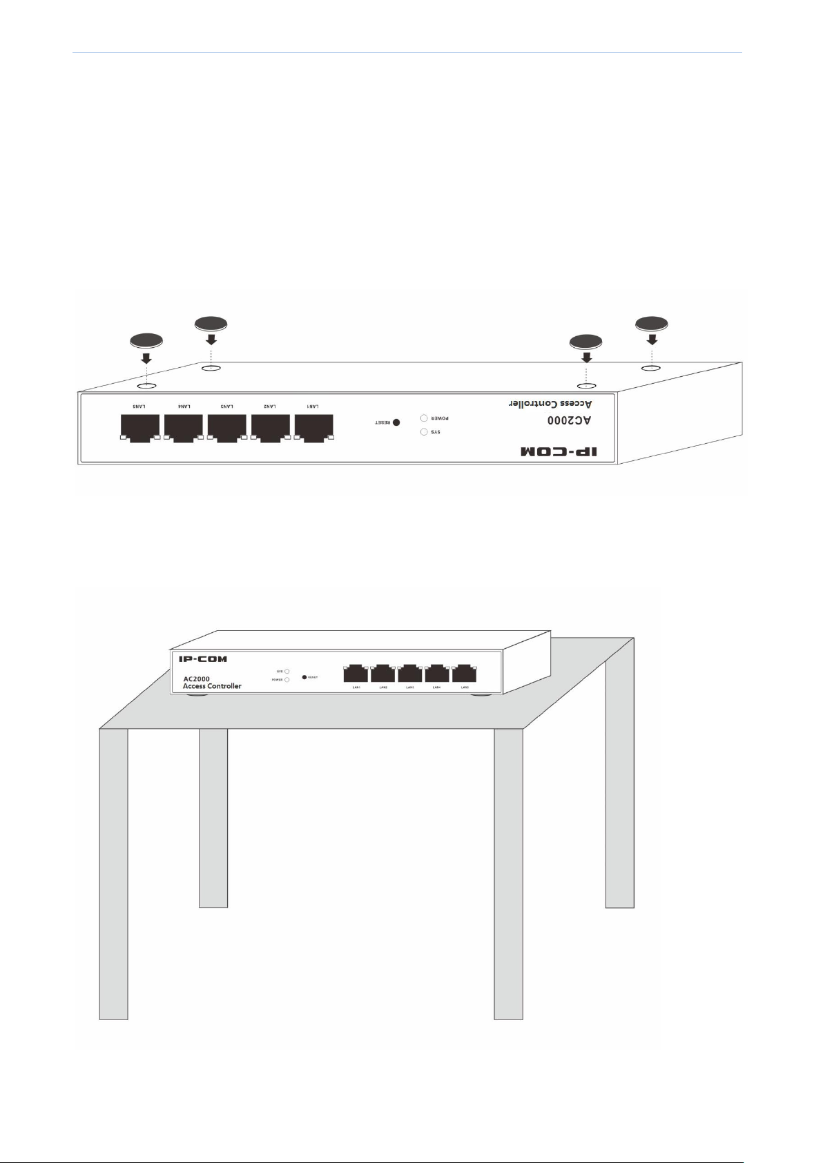
2.2.2 Workbench Installation
If you don’t have a standard 19-inch rack, please use a workbench to install the access controller.
The installation steps are as follows:
Step 1: Place the access controller upside down on a workbench which is big enough, clean and steady.
Step 2: After removing the rubber-faced protective paper of the four anti-slip footpads one by one, stick the pads
into the round grooves corresponding to four corners of the housing undersurface respectively.
Step 3: Flip the access controller for placement on the workbench with face up.
The workbench installation completes.
Page 13
Page 24

Device Installation
2.3 Power on the Device
First, connect the access controller’s power port to a power outlet with the power cord in the package.
And then press the power switch on the access controller’s rear panel to power on the access controller. After
powered on, the access controller automatically conducts initialization.
Check the indicators which should show the following one by one:
All indicators (POWER, SYS and LINK/ACT) are on for self-inspection.
POWER and SYS remain on, and others are all off.
After startup, The POWER indicator is on, the SYS indicator blinks, the LINK indicator of the LAN port which has
connected to other active network devide is on, and the ACT indicator is off or blinks.
Page 14
Page 25

Web Login
Login Information
Default Value
IP address
192.168.10.1
Username
admin
Password
admin
3 Web Login
3.1 Login
This access controller provides the Web UI to help the administrator manage and maintain the access controller
easily. When using the access controller for the first time, you can log in to the access controller’s Web UI via a
browser with default login information. The access controller’s default login information includes:
Login Steps: (assuming that the access controller’s login information is the default value)
Step 1: Connect the managing PC to any LAN ports of the access controller with an ethernet cable.
Page 15
Page 26
Web Login
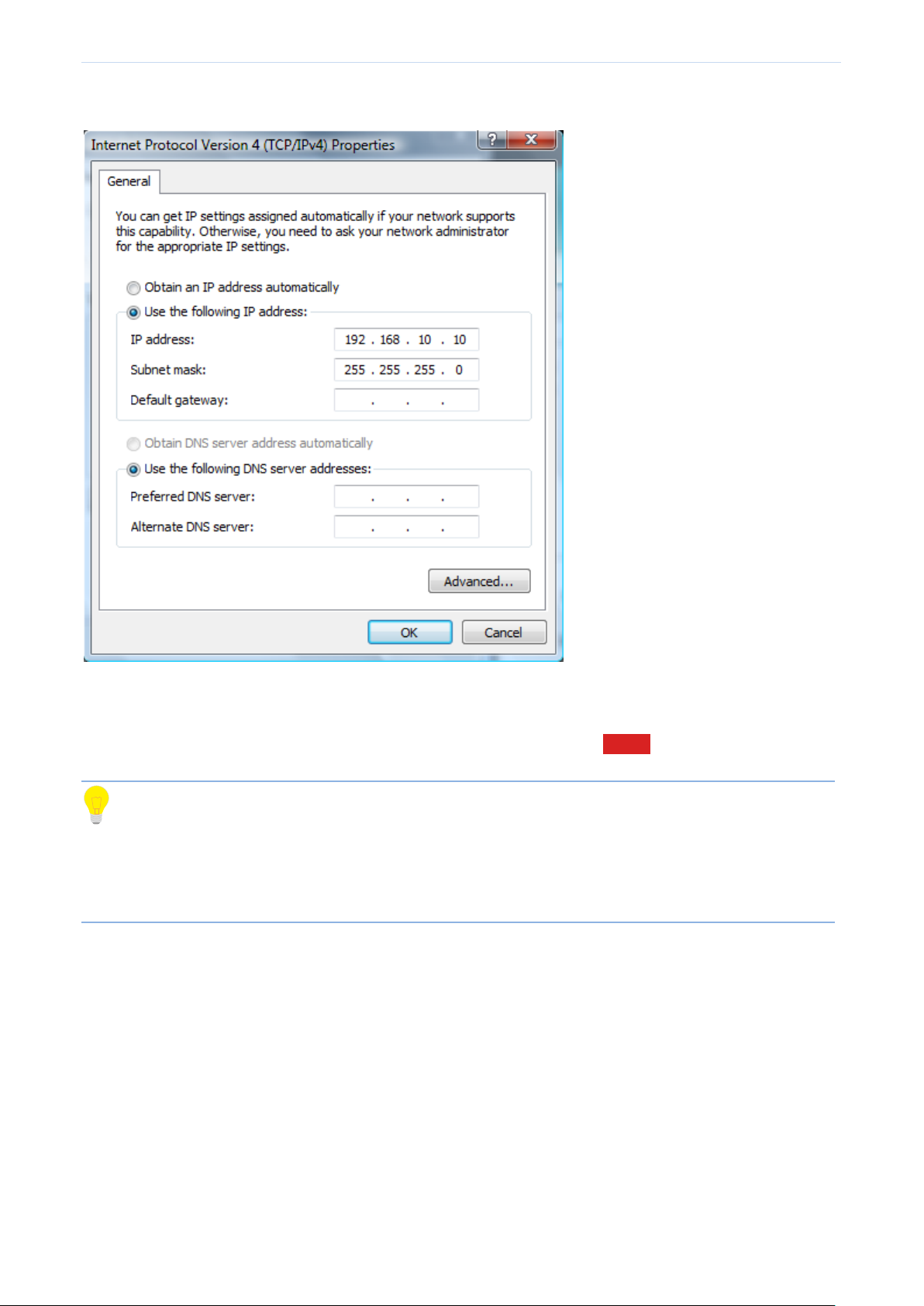
Step 2: Set the local IP address of the PC to “192.168.10.X” (X is in the range of 2~254), with a subnet mask of
“255.255.255.0”.
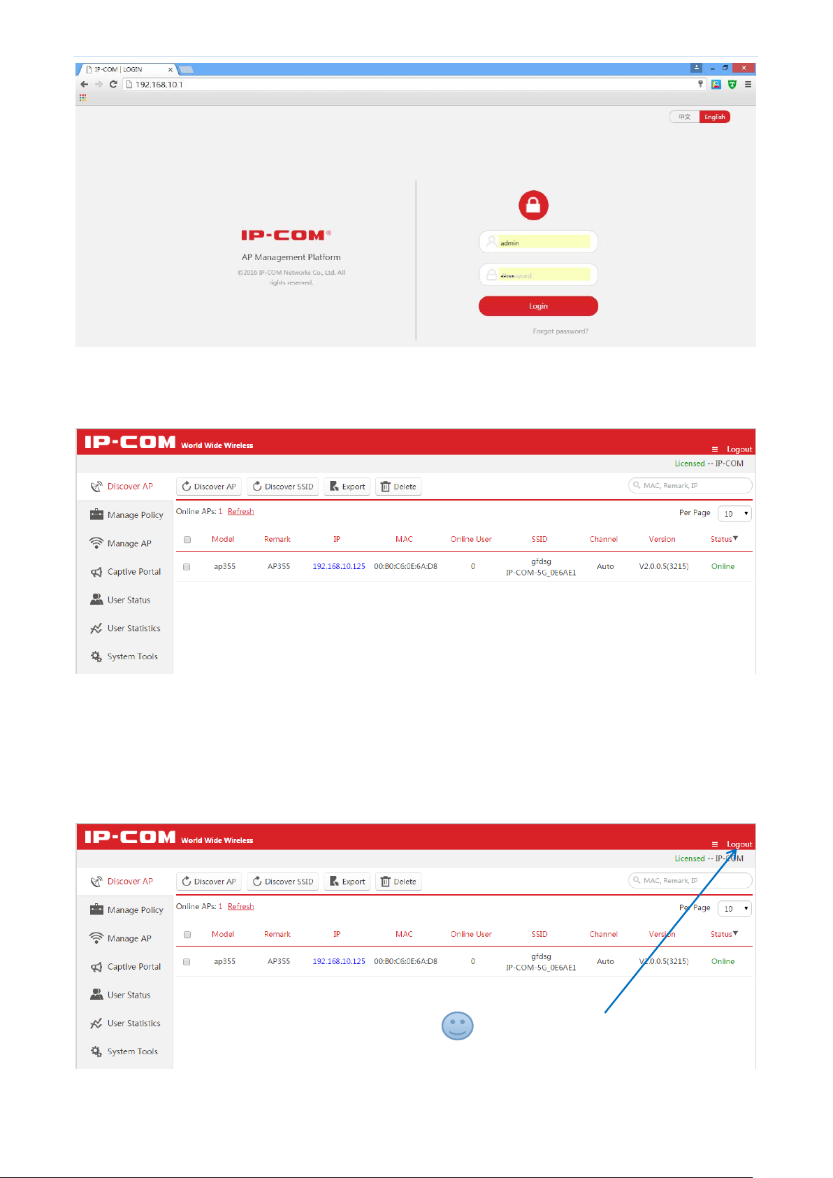
Step 3: Launch a browser on the PC, enter “192.168.10.1” in the address bar, and then press “Enter” or “Return”.
Step 4: After entering “admin” for both the username and the password, click Login .
Tip
If the following page does not appear, please refer to Question 1 in Appendix.
The Web UI of this access controller supports both Chinese and English, between which you can choose
based on your needs. This user guide gives a description in English.
Page 16
Page 27
Web Login
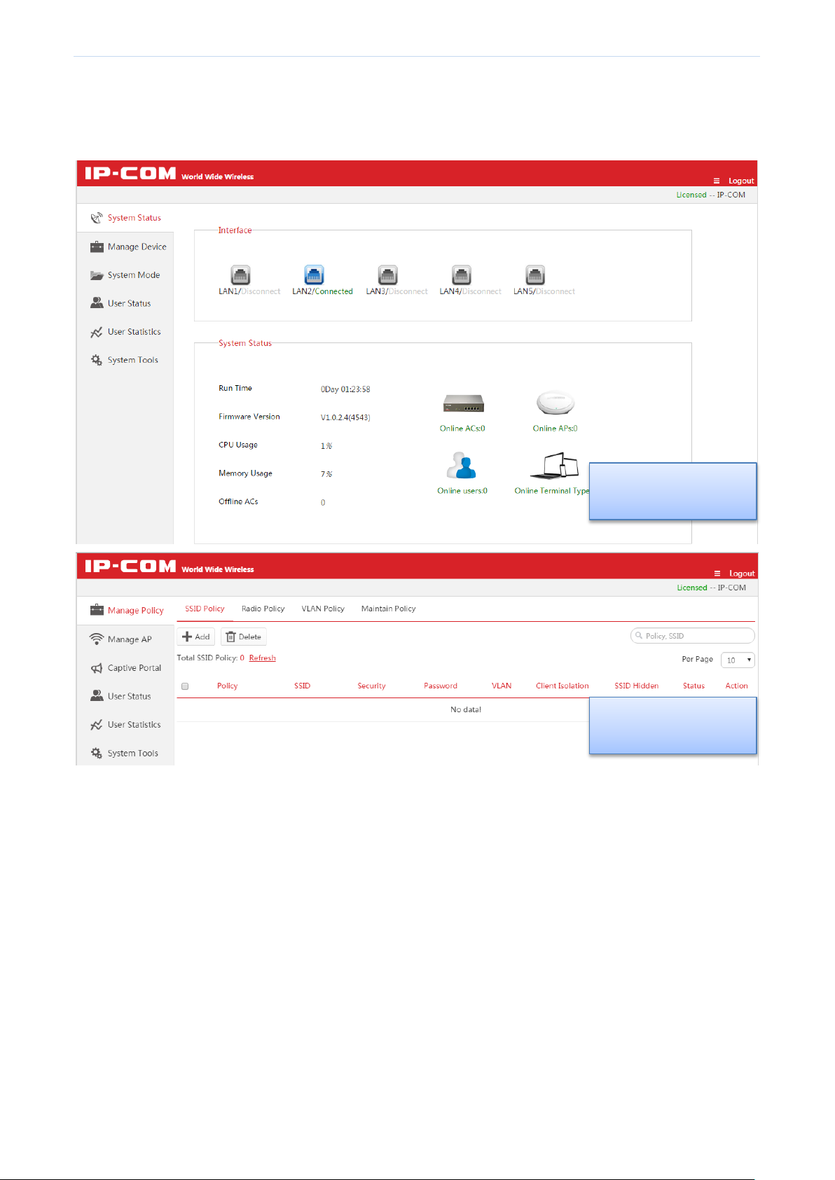
Step 5: After logging in to the access controller’s Web UI successfully, the following page appears. For detail
configurations, please refer to the next few charpers.
3.2 Logout
Close the browser window directly or click “Logout” on the top right corner to safely exit from the access
controller’s Web UI.
Click it to safely exit from the Web UI
Page 17
Page 28

Web Login
Number
Name
Description
1
Primary navigation
bar
The navigation bar organizes the access controller’s menu of all functions in
the form of a navigation tree. The user can easily choose the function menu
from the navigation bar, with selection result shown in the configuration
area.
2
Secondary
navigation bar
3
Configuration area
The area is for users to configure and view.
Sub AC Mode
3.3 Layout of Web UI
The Web UI is divided into three parts: primary navigation bar, secondary navigation bar and configuration area,
as shown in the following figure.
Page 18
Page 29
Web Login
Root AC Mode
Cloud AC Mode
The access controller supports three working modes: Root AC, Sub AC and cloud AC, which have different Web
management pages. The access controller works in the “Sub AC” mode by default. If you want to switch the
working mode, go to System Tools Maintain System Mode for operations.
Page 19
Page 30

Web Login
Element
Description
(Top right corner of the
homepage)
Click it to unfold .
Search bar, for entering key words to find and locate the information. For supported
key words, see the input box prompt.
Click the drop-down box to select how many pieces of information to be displayed
on each page.
Click to refresh displayed information.
Click to edit corresponding information.
Check one: Select only one item.
Check all: Select all items displayed on the page.
This indicates that the access controller has been authorized for activation and can
be used normally.
Button
Description
Click to delete the selected information in “Offline” or “Unused” status.
Click to save and make current page configurations take effect.
3.4 Elements of Web UI
The descriptions of common elements are as follows.
The descriptions of common buttons are as follows:
Page 20
Page 31

Cloud AC Mode
4 Cloud AC Mode
4.1 Cloud AC Mode Introduction
When the wireless network is distributed in various regions and each one is on a small scale but the total
network is on a large scale, you can deploy one access controller to work in “Cloud AC” mode for centralized
management of cloud APs scattered everywhere. (The cloud APs must be in the “Cloud” Deployment mode, refer
to AP Configuration). The following is a specific application example.
Networking Requirements
A national chain-restaurant needs to achieve wireless coverage. Requirements are as follows:
Customers in each branch can surf the Internet with the provided WiFi network, and can view the
advertisements of newest menus from the restaurant.
The administrator at the headquarters can view the instant status of cloud APs in all branches, and can
deliver configuration policies and advertisements to cloud APs, to achieve remote management and
diagnosis, without visiting each branch.
Page 21
Page 32

Cloud AC Mode
Page 22
Page 33

Cloud AC Mode
Scheme Design
To create an exclusive wireless network for the restaurant, you can use IP-COM access controller + AP to work
together. Details are as follows:
At the restaurant headquarters, deploy an access controller AC2000, working in the "Cloud AC" mode, for
centralized management of the distributed regional cloud APs.
In every branch, deploy one or more APs, working in the "Cloud" Deployment mode, and specify the "Cloud
AC Address" to the public IP address or domain name of the headquartes’ gateway.
The gateway, connecting the access controller at the headquarters, should enable two ports to the public
network, one for managing cloud AP and the other for upgrading cloud AP.
On the access controller, configure and deliver advertisements to cloud APs in each branch. Thus customers
can view the advertisements from the restaurant before surf the Internet.
Assumptions are as follows:
The domain name, binding to the public IP address of the gateway which connects the access controller, is
"head.noip.com".
The LAN IP address of the gateway, which connects the access controller, is 192,168.20.100, with DNS proxy
function.
The gateway, which connects the access controller, has enabled two ports to the public network: "8888" for
managing the cloud APs and "8899" for upgrading cloud APs.
Network Topology
Page 23
Page 34

Cloud AC Mode
Access Controller Configuration
The configuration steps are as follows: (Assume that the access controller works in "Sub AC" mode by default.)
1. Log in to the Web UI of the access controller, and go to System ToolsMaintain System Mode.
2. Enter the Device Name of the “Cloud AC”, such as “Headquarters”.
3. Select "Cloud AC" mode in the Working Mode line.
4. Enter "8888" in the Manage Port box.
5. Enter "8899" in the Firmware Upgrade Port box.
6. Click OK and wait for the access controller to complete the reboot process.
Page 24
Page 35

Cloud AC Mode
7. Log in to the Web UI of the access controller again and go to System ToolsNetwork SettingLAN Settings
to configure the corresponding parameters to make the access controller connect to the Internet through the
gateway. In this example, we configure the parameters as follows.
Tip
After the access controller connects to Internet successfully, you can go to Manage AP to view the information of
cloud APs in each branch.
8. Go to Captive Portal, and create advertisements and deliver them to cloud APs of each branch.
For details, please refer to 4.4 Captive Portal.
Page 25
Page 36

Cloud AC Mode
AP Configuration
The configuration steps are as follows: (Here we take AP355 as an example.)
1. Log in to the Web UI of AP, go to Deployment and select "Cloud".
2. Set up Device Name as you like. In order to manage different AP easily, it is recommended to set up the
Device Name as AP’s branch name or location. Here we take "Branch_1" as an example.
3. Enter "head.noip.com" in the Cloud AC Address box.
4. Enter "8888" in the Cloud AC Manage Port box.
5. Enter "8899" in the Cloud AC Upgrade Port box.
6. Click Save to apply your settings.
7. Go to NetworkLAN Setup, and set up the AP's IP address information to make it connect to the Internet.
4.2 Manage Policy
Tip
Configuration in this section also applies to 5.3 Manage Policy in "Sub AC" mode.
To create SSID Policy, Radio Policy, VLAN Policy, and Maintain Policy, you can use this section to help you.
After creating appropriate policies, you can deliver these policies to the APs in Manage AP page. For details, refer
to 4.3 Manage AP.
Page 37

Cloud AC Mode
Click the button to add a new SSID policy.
Click the button to delete the selected SSID policies in "Not Used" status.
(Action)
Modify the parameters except Policy name.
Tip
It is not recommended to modify the “Used” policies.
4.2.1 SSID Policy
SSID Policy Overview
To create a SSID policy, click Manage Policy SSID Policy to enter the following page.
SSID parameters include SSID name, Security key, VLAN ID, and so on.
This page displays the basic information of SSID policies.
Buttion Description:
Add SSID Policy
To create a SSID policy, click + Add . This access controller supports creating up to 40 SSID policies.
Page 38

Cloud AC Mode
Item
Description
Policy
Enter a unique SSID Policy name.
SSID
Enter a SSID name. The range of Length is 1~32 bytes.
Parameter description
Page 39

Cloud AC Mode
Item
Description
Security
The access controller supports the following three types of Security Mode:
No encryption: If you select this option, all clients can connect to your WiFi. In order to
ensure network security, it is not recommended to select this one.
WPA-PSK: The security mode of the wireless network is WPA-PSK.
WPA2-PSK: The security mode of the wireless network is WPA2-PSK.
Encryption
(Available only when WPA-PSK or WPA2-PSK is selected.)
The access controller supports the following three types of encryption:
AES: AES is short for Advanced Encryption Standard. This encryption algorithm ensures
a higher wireless rate.
TKIP: TKIP is short for Timing Key Integrity Protocol. Wireless rate can only reach
54Mbps with this algorithm.
TKIP&AES: Compatible with TKIP and AES. The wireless client can use either AES or
TKIP algorithm to connect to the WiFi.
Security Key
(Available only when WPA-PSK or WPA2-PSK is selected.)
Wireless clients need to enter this security key to conncet to a corresponding AP.
The range of length is 8~63 characters.
Key interval
(Available only when WPA-PSK or WPA2-PSK is selected.)
Configure the key update interval for encrypting WPA data. Theoretically, the shorter the
key interval is, the more secure the WPA data will be. If set to “0”, the key will not be
updated.
Client Limit For
SSID
Set the maximum number of wireless clients allowed to connect, the range is 1~64.
If this value is greater than AP’s the maximum supported number, the latter takes effect
after the policy is delivered.
Client Isolation
Enable/Disable the SSID "client isolation".
Enable: Wireless clients that connect to the SSID can't communicate with each other.
Disable: Wireless clients that connect to the SSID can communicate with each other.
SSID Hidden
Enable/Disable "hide SSID" function.
Enable: If you enable “SSID Hidden” function, the SSID name will not be broadcasted
so that the SSID names can not be found in the clients' available network list. Wireless
clients need to manually enter the SSID name to connect to the SSID.
Disable: The SSID name will be broadcasted and will be discovered by adjacent
devices.
Page 40

Cloud AC Mode
Item
Description
VLAN ID
Set VLAN ID of the SSID and all packets from connected clients will be tagged with this
VLAN ID. The range is 1~4094.
Note
VLAN ID is not effective unless VLAN Policy is delivered.
Status
Display whether the Policy is used or not.
Action
Modify the parameters except Policy name.
Tip
It is not recommended to modify the “Used” policies.
Click the button to add a new Radio policy.
Click the button to delete the selected Radio plicies in “Not Used” status.
(Action)
Modify the parameters except Policy name.
Tip
It is not recommended to modify the “Used” policies.
4.2.2 Radio Policy
Radio Policy Overview
To create a radio policy, click Manage Policy Radio Policy to enter the following page.
Radio Policy parameters include 5G Prority, Radio, Mode, Bandwidth, Channel, Time Age, and so on.
This page displays the basic information of Radio policies.
Buttion Description:
Page 41

Cloud AC Mode
Drag down to display all
Add Radio Policy
To add a radio policy, click + Add .
the contents.
Page 42

Cloud AC Mode
Item
Description
Policy
Enter a unique Radio Policy name.
Radio
Support 2.4G and 5G band. Different radio provides different signal strength and quality over
different distance ranges. Signals in the 2.4 GHz band tend to pass through physical barriers
better and carry farther than those in the 5 GHz band, but they do not provide as high a data
rate. Signals in the 5 GHz band provide faster data rates for better throughput, but the signal
attenuates faster and is best suited for open spaces. As 5 GHz signal does not travel as far as
2.4 GHz signal, you may need more APs for 5G range.
WIFI
Enable/disable 2.4G or 5G radio.
Airtime
scheduling
It is recommended to enable this function.
Dynamic airtime scheduling gives equal airtime rather than frame transmission opportunity
to clients, thereby allowing high-speed clients to achieve much higher throughput without
significantly impacting the slow-speed clients.
Country
Countries apply for their own regulations to the allowable channels, allowed users and
maximum power levels within the frequency ranges. Consult your local authorities as these
regulations may be out of date as they are subject to change at any time. Most contries allow
the first eleven channels in the spectrum.
Network Mode
Select a Network Mode. 2.4G band includes 11b, 11g, 11b/g and 11b/g/n, while 5G band
includes 11a, 11ac and 11a/n. Descriptions are as follows.
11b: Works in 2.4G band and supports up to 11 Mbps.
11g: Works in 2.4G band and supports up to 54 Mbps.
11b/g: If you select this option, wireless clients supporting 802.11b or 802.11g can
connect to the WiFi.
11b/g/n: If you select this option, wireless clients supporting 802.11b, 802.11g or
802.11n can connect to the WiFi.
11a: Works in 5G band and supports up to 54 Mbps.
11ac: Works in 5G band and supports up to 1300Mbps. It is a newer standard that uses
wider channels, QAM and spatial streams for higher throughput
11a/n: Works in 5G band and supports up to 300Mbps, compatible with 11n.
Parameter description
Page 43

Cloud AC Mode
Bandwidth
Select the wireless bandwidth.
20: 20MHZ channel bandwidth.
40: 40MHZ channel bandwidth.
80: 80MHZ channel bandwidth.
Auto: Automatically adjust the channel bandwidth to 20MHZ or 40MHZ based on
surrounding environment.
Channel
Select the wireless channel. Channel range differs from country and radio band.
Extension
Channel
When bandwidth is 40 or Auto, this is used to determine the channel range of AP.
TX power
AP wireless transmit power, range: 1~99dBm. If this value is greater than the maximum
supported power of an AP, the latter takes effect after the policy is delivered.
RSSI Threshold
RSSI is short for Received Signal Strength Indication.
If a wireless client’s signal is lower than this value, the client can not connect to the AP, which
helps the client to connect to an AP with stronger signal.
WMM
Wi-Fi Multimedia (WMM) provides basic Quality of Service (QoS) features to IEEE 802.11
networks. WMM prioritizes traffic according to four Access Categories (AC) - voice, video,
best effort, and background. However, it does not provide guaranteed throughput. It is
suitable for well defined applications that require QoS, such as Voice over IP (VoIP) on Wi-Fi
phones (VoWLAN).
SSID Isolation
Enable/Disable SSID isolation.
When enabled, wireless clients that connect to different SSID of the AP cannot communicate
with each other.
APSD
APSD is short for Automatic Power Save Delivery. It is basically a feature mode that allows
your mobile devices to save more battery while connect to your WiFi network. By allowing
your mobile devices to enter standby or sleep mode, it conserves energy. It is only effective
when you enable WMM.
Time Age For
Client
After a client connects to the AP:
If there is no data transmission within the time period, AP will actively disconnect the client.
If data transmission is detected within the time period, AP will recalculate the time age.
5G priority
"5G priority" refers to a scenario when a dual band client connects to a dual band AP, the AP
makes it connect to 5G band in higher prority, which helps the AP to reduce interference and
workload in 2.4G band and hence improve user experience.
Page 44

Cloud AC Mode
Status
Display whether the Policy is used or not.
Action
Modify the parameters except Policy name.
Tip
It is not recommended to modify the “Used” policies.
Click the button to add a new VLAN policy.
Click the button to delete the selected VLAN policies.
Action
Modify the parameters except Policy name.
Tip
It is not recommended to modify the “Used” policies.
4.2.3 VLAN policy
VLAN policy Overview
To create a VLAN policy, click Manage Policy VLAN Policy to enter the following page.
VLAN policy includes AP's PVID, management VLAN, trunk ports, and so on.
This page displays the basic information of VLAN policies.
Buttion Description:
Add VLAN policy
To add a VLAN policy, go to Manage Policy VLAN Policy, and click + Add .
Page 45

Cloud AC Mode
Item
Description
Policy
Enter a unique VLAN Policy name.
AP VLAN
Enable/disable AP's 802.1Q VLAN feature.
After this feature is enabled and this VLAN policy is delivered to AP, "VLAN ID" in Manage
Policy SSID policy takes effect.
PVID
Enter AP Trunk port’s default VLAN ID. It is recommended to set to “1”.
Manage Vlan
AP's Management VLAN ID.
Note:
If you modify this value and deliver this VLAN policy to AP, you need to go to System
Tools Network setting VLAN Settings to set the same VLAN ID to the AC and
reboot the AC. Only after that, the AC can manage AP again.
Only when a management computer and an AP are in the same VLAN, can the
computer access the AP's Web UI.
Trunk Mode
Select wired LAN port as a trunk port which allows all VLAN packets to pass.
Note: If AP has only one LAN port, select LAN0.
Access Mode
Display the port(s) in access mode. If a port has been a trunk port, it cannot be an access
port.
Parameter description
Page 46

Cloud AC Mode
LAN 0
LAN 1
Set up the Access port's VLAN ID.
Status
Display whether the Policy is used or not.
Action
Modify the parameters except Policy name.
Tip
It is not recommended to modify the “Used” policies.
Click the button to add a new Maintain Policy.
Click the button to add a new Alert Policy.
Click the button to add a new Password Policy.
Click the button to add a new Deployment Policy.
Click the button to delete the selected policies in “Not Used” status.
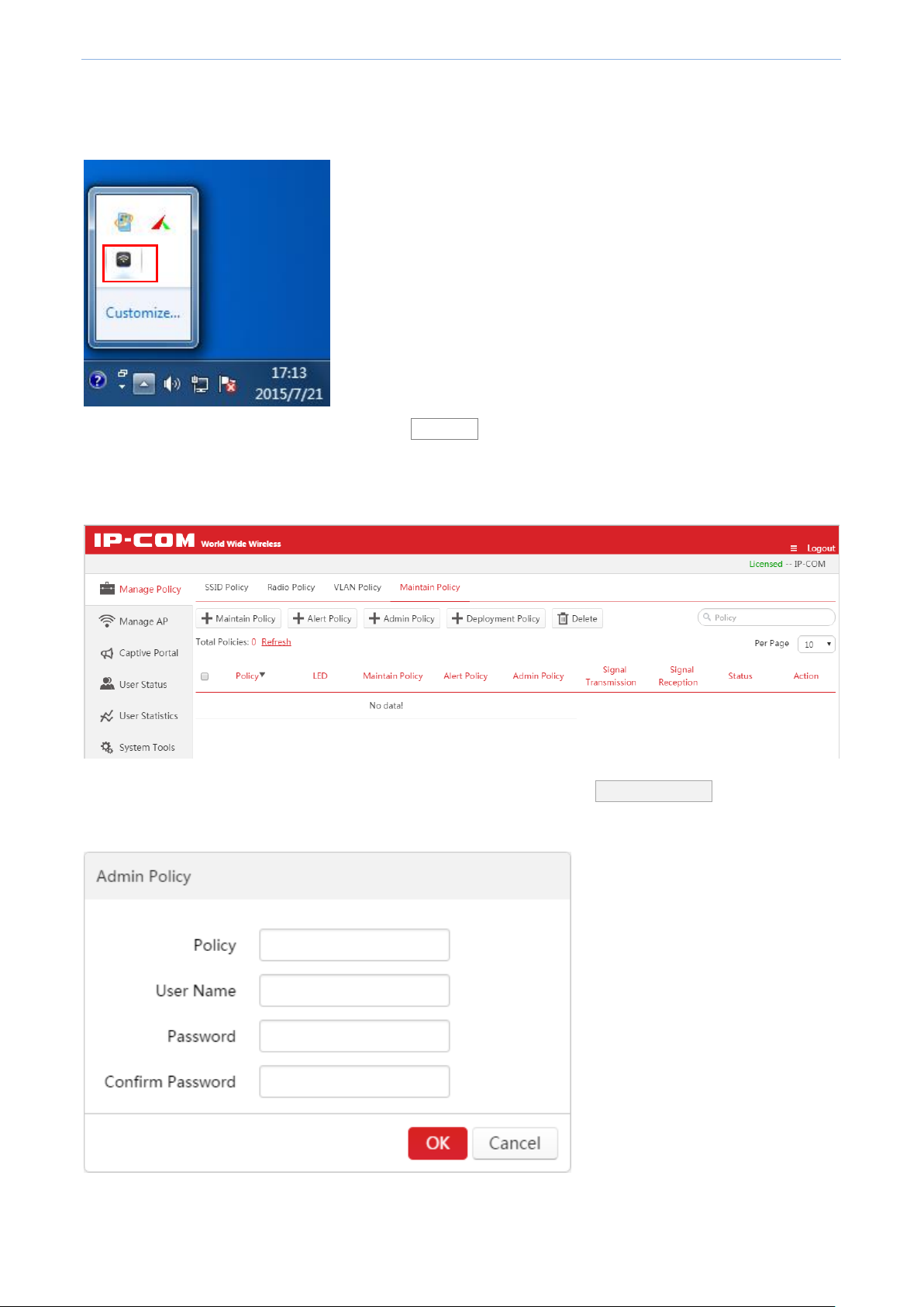
4.2.4 Maintain Policy
To create a maintain policy, alert Policy, admin Policy or deployment policy, click Manage Policy Maintain
Policy to enter the following page.
Buttion Description:
Page 47

Cloud AC Mode
Item
Description
Policy
Display the unique name of a policy.
LED
If the policy is a maintain policy, it displays the LED status: enable or disable.
Otherwise, it displays “----”.
Maintain/Alert/Admin
Policy
Display corresponding information of a Maintain/Alert/Admin Policy.
Signal Transmission
Signal interference between APs can be effectively reduced by adjusting the transmit
power of AP. If it is a capacity-oriented network, please select “High Density”.
Otherwise, select “Coverage”.
Signal Reception
Select a Signal Reception Method based on different scenarios.
Coverage: It is used in a coverage-oriented network to ensure a higher WiFi coverage.
High Density: It is used in a capacity-oriented network to ensure a better signal quality.
Default: The signal reception is between “Coverage” and “High Density”.
Status
Display whether the Policy is used or not.
Action
Modify the parameters except Policy name.
Tip
It is not recommended to modify the “Used” policies.
This page displays summary about maintain policy. Parameters are described below:
Maintain Policy
This section helps you to configure the maintain policy, including LED status and auto reboot time.
Click + Maintain Policy to add a maintain policy.
Page 48

Cloud AC Mode
Item
Description
Policy
Enter a unique maintain Policy name, which cannot be the same with other
maintain/alert/admin/deployment policies.
LED
Enable/Disable AP’s LED indicators.
Auto Maintain
Enable/Disable AP’s auto reboot feature. If enabled, the AP will automatically reboot at a
specified time (recommended in leisure time) to ensure AP’s performance.
Maintain Type
Select AP reboot type.
Circularly: The AP will automatically reboot periodically at a specified interval.
Schedule: The AP will automatically reboot at specified date and time.
Maintain Time
Specify AP reboot interval when Circularly is selected.
Maintain
Time(Schedule)
Specify AP reboot time when Schedule is selected.
Everyday, Mon,
Tue, Wed, Thu, Fri,
Sat, Sun
Specify AP reboot date when Schedule is selected.
Parameter description
Page 49

Cloud AC Mode
Item
Description
Policy
Enter a unique alert Policy name, which cannot be the same with other
maintain/alert/admin/deployment policies.
Drag down to display all
Alert Policy
This section helps you to configure AP Alert Policies, including Software Alert, Email Alert, and AP alert
configurations.
Click + Alert Policy to add an alert policy.
Parameter Description:
the contents.
Page 50

Cloud AC Mode
Software Alert
Enable/Disable the software alert function.
When enabled, please enter IP address of the host which receives alert logs, and the
access controller will send alert logs directly to the alert client program running on the
host.
Tip: For the description of alert client program, please refer to Running Alert Client.
Email Alert
Enable/Disable Email Alert function. When enabled, please enter an email address for
sending/receiving AP alert logs, and the access controller will regularly send alert logs
using the email address to the same email address of the network administrator.
E-mail password
Enter the sending email password.
Alert Interval
When you enable the email alert function, please enter the interval of sending alert logs.
AP Failure Alert
Enable/Disable AP Failure Alert. If enabled, the access controller will send alert logs, such
as AP reboot, AP online or offline, and so on.
AP Traffic Alert
Enable/Disable AP Traffic Alert. If enabled, the access controller will send alert logs when
AP traffic reaches its limit.
Traffic Limit
The access controller will send alert logs when AP traffic reaches this limit.
AP Client Alert
Enable/Disable AP Client Alert. The access controller will send alert logs when the number
of connected clients reaches its limit.
Client Limit
The access controller will send alert logs when AP's connected clients reach this number.
Running Alert Client: (Take Windows 7 for example)
1. Contact IP-COM technical support engineer to get alert client software.
2. Save the software in a specified folder on a computer, e.g. "D:\AP_alarm".
3. Double-click the icon .
If the "Do you want to allow the following program from unknown Publisher to make changes to this computer"
dialogue prompts, click Yes .
After a successful installation, it will generate the following two files in the folder:
The AC will send AP's alert logs to this file on the host. Please make sure to keep the file.
This is the system temporary file, ignore it.
Page 51
Cloud AC Mode
The network administrator can view AP's alert logs on the alert client program. Do as follows.
1. Double-click the alert client icon.
2. View AP alert logs on the pop-up page. Click Refresh to view the latest alert logs.
Admin Policy
This section helps you to configure login account and password of AP. Click + Admin Policy to add an Admin
policy. The access controller supports up to 10 Admin policies.
Page 52

Cloud AC Mode
Item
Description
Policy
Enter a unique Admin Policy name, which cannot be the same with other
maintain/alert/admin/deployment policies.
User name
Set up AP's login account. It supports letters (case-sensitive), numbers, and underscores.
The range of length is 3~32 characters.
Password
Set up AP's login password. It supports letters (case-sensitive), numbers, and
underscores. The range of length is 3~32 characters.
Confirm Password
Repeat the password.
Parameter Description:
Deployment Policy
This section helps you to configure deployment policies, including Signal Transmission, Signal Reception, and
Ethernet Mode.
Click + Deployment Policy to add a deployment policy.
Parameter Description:
Page 53

Cloud AC Mode
Item
Description
Policy
Enter a unique SSID deployment policy name, which cannot be the same with other
maintain/alert/admin/deployment policies.
Signal
Transmission
Signal interference between APs can be effectively reduced by adjusting the transmit
power of AP. If it is a capacity-oriented network, please select “High Density”. Otherwise,
select “Coverage”.
Signal Reception
Select a Signal Reception Method based on different scenarios.
Coverage: It is used in a coverage-oriented network to ensure a higher WiFi coverage.
High Density: It is used in a capacity-oriented network to ensure a better signal quality.
Default: The signal reception is between “Coverage” and “High Density”.
Ethernet mode
Select AP LAN port's Ethernet mode. The default option is “10M Half-Duplex”. This mode
can transmit in a longer distance with lower speed. When the distance between AP and
the other device are more than 100 meters, please select "10M half-duplex" to make
signal travels further. You must ensure that the other device works in auto negotiation
mode, or AP LAN port can't send and receive data.
Page 54

Cloud AC Mode
Click this button to deliver a SSID Policy to selected online APs.
Click this button to deliver a Radio Policy to selected online APs.
Click this button to deliver a VLAN Policy to selected online APs.
Click this button to deliver a Maintain Policy to selected online APs.
Click this button to restore the maintain policy and alert policy of the selected online
APs to factory default.
Click the button to delete the selected "offline" APs.
4.3 Manage AP
Tip
Configuration in this section also applies to 5.4 Manage AP in Sub AC mode.
To deliver the configured policies to appropriate APs and manage the APs, use this section to help you.
This section includes two parts, AP Group Modify and AP Modify.
4.3.1 AP Group Modify
Overview
To deliver SSID policy, radio policy, VLAN policy and maintain policy to APs, click Manage AP AP Group Modify
to enter the following page.
Buttion Description:
Page 55

Cloud AC Mode
Item
Description
Model
Display AP model.
Remark
Display AP remark. In order to manage different AP easily, it is recommended to set up the
Remark name as AP’s branch name or location.
MAC
Display AP MAC address.
SSID
Display AP’s SSID(s). If more than one SSID is delivered to AP, it displays all SSID names
when the cursor is hovering over.
Radio Policy
Display the delivered radio policy name.
VLAN policy
Display the delivered VLAN policy name.
Maintain Policy
Display the delivered maintain policy name.
Alert Policy
Display the delivered alert policy name.
Admin Policy
Display the delivered admin policy name.
Deployment
Policy
Display the delivered deployment policy name.
Status
Display whether the AP is online or offline.
Online: The AP and AC have successfully established a connection, and the AC can manage
the AP.
Offline: The AP and AC failed to establish a connection and the AC can't manage the AP.
Tip
If the AP is offline, it keeps configuration delivered before. Users can still use their wireless
network unless the AP is restored to factory default.
Parameter Description:
Page 56

Cloud AC Mode
☺
If an AP does not support 5G
band, the 5G band will not be set.
If some of the selected APs
support 2.4G and others support
2.4G and 5G, then the AC will
automatically deliver policies
based on AP's actual supported
If an AP only supports 2 SSIDs,
then policies after policy 2 will not
be delivered even if you select
SSID Setting
To deliver SSID policies to online APs, do as follows:
1. Select online APs.
2. Click SSID Setting .
3. In the drop-down list, select the SSID policy name.
4. Click Save .
The SSID policies will be delivered to the selected APs.
Tips:
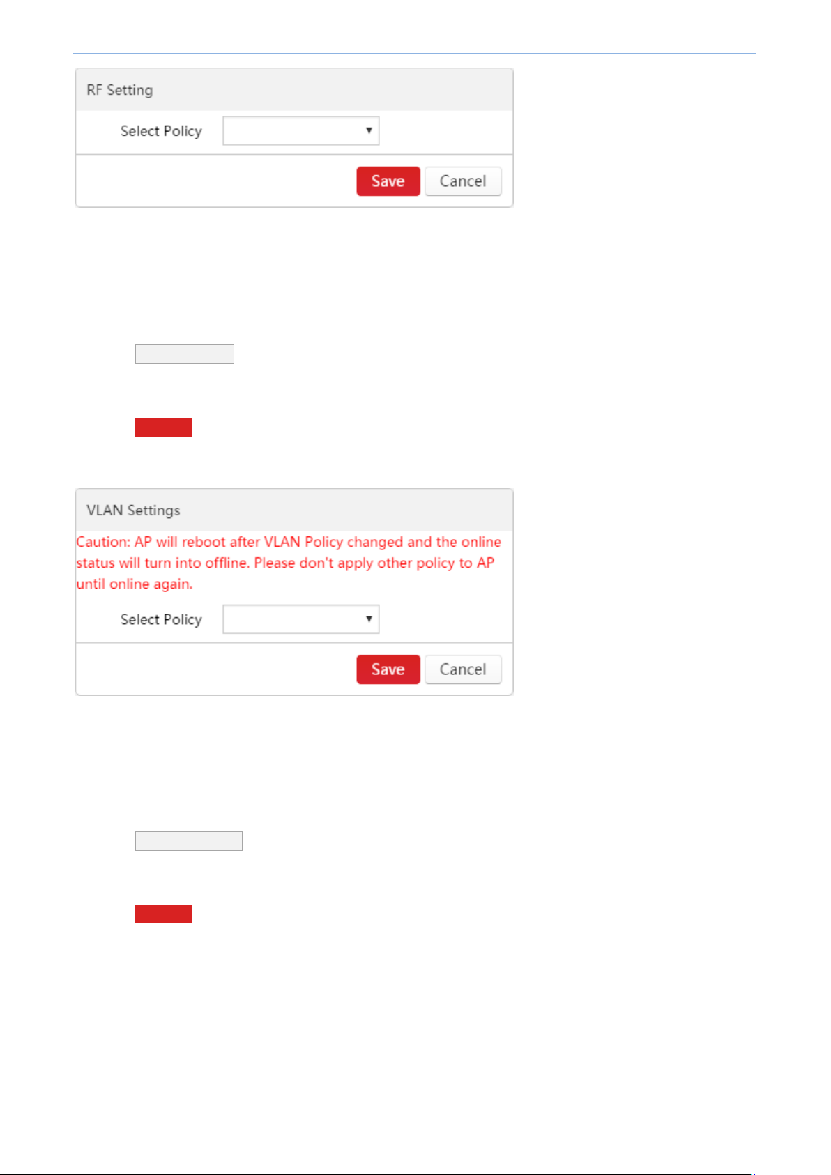
RF Setting
To deliver a RF policy to online APs, do as follows:
1. Select online APs.
2. Click RF Setting .
3. In the drop-down list, select the policy name.
band.
more than 2 SSIDs.
4. Click Save .
The RF policy will be delivered to the selected online APs.
Page 57
Cloud AC Mode
VLAN Settings
To deliver a VLAN policy to online APs, do as follows:
1. Select online APs.
2. Click VLAN Settings .
3. In the drop-down list, select the policy name.
4. Click Save .
The VLAN policy will be delivered to the selected APs.
Maintain Setting
To deliver maintain policies to online APs, do as follows:
1. Select online APs.
2. Click Maintain Policy .
3. In the drop-down list, select the corresponding policy name.
4. Click Save .
The maintain policies will be delivered to the selected APs.
Page 58

Cloud AC Mode
Clear Settings
To restore maintain policy and alert policy of the selected online APs to factory default. Do as follows:
1. Select online APs.
2. Click Clear Settings .
Tip:
Other policies will not be restored to factory default.
The maintain policy here does not include Alert Policy, Admin Policy or Deployment Policy.
Delete
To delete offline APs:
1. Select the APs.
2. Click Delete .
Tip:
Online APs will not be deleted even if you select them.
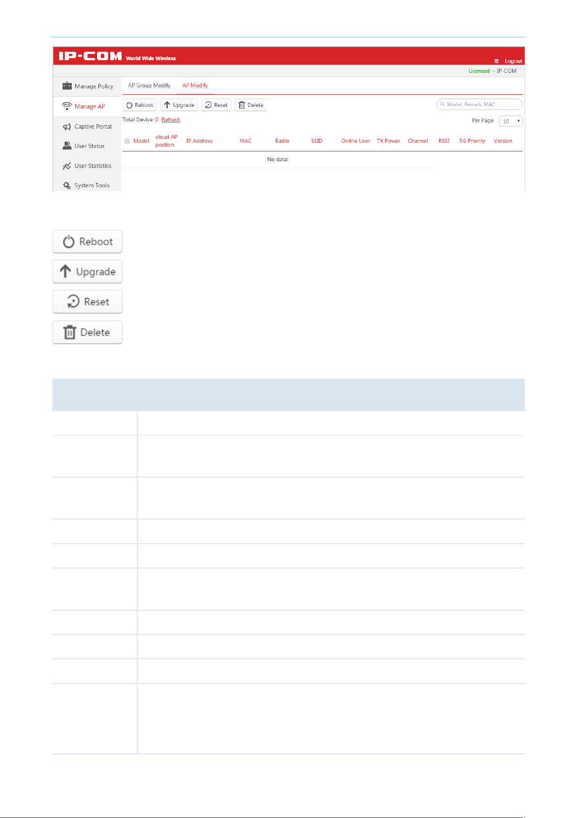
4.3.2 AP Modify
Overview
To reboot, upgrade and reset selected online APs, to delete selected offline APs or to change RF settings of an AP,
click Manage AP AP Modify to enter the following page.
Page 59
Cloud AC Mode
Click the button to reboot the selected online APs.
Click the button to upgrade a firmware for the selected online APs.
Click the button to restore the selected online APs to factory default.
Click the button to delete the selected offline APs.
Item
Description
Model
Display AP model.
Cloud AP position
Display AP remark. In order to manage different AP easily, it is recommended to set up the
“Cloud AP position” as its branch name or location.
IP address
Display the public IP address of the cloud AP. It is generally the public IP address the cloud
AP’s gateway.
MAC
Display AP MAC address.
Radio
Display the AP's frequency band. It may be 2.4G or 5G or 2.4G and 5G.
SSID
Display AP’s SSID(s). If more than one SSID is delivered to AP, it displays all SSID names
when the cursor is hovering over.
Online Users
Display the amount of online users which connect to the AP.
TX Power
Display the AP's wireless transmit power.
Channel
Display the AP’s channel.
RSSI
RSSI is short for Received Signal Strength Indication.
If a wireless client’s signal is lower than this value, the client can not connect to the AP,
which helps the client to connect to an AP with stronger signal.
Operation button's description:
Parameter Description:
Page 60

Cloud AC Mode
5G Priority
"5G priority" refers to a scenario when a dual band client connects to a dual band AP, the
AP makes it connect to 5G band in higher prority, which helps the AP to reduce
interference and workload in 2.4G band and hence improve user experience.
Version
Display the firmware version of the AP.
Status
Display whether the AP is online or offline.
Online: The AP and AC have successfully established a connection, and the AC can manage
the AP.
Offline: The AP and AC failed to establish a connection and the AC can't manage the AP.
Tip
If the AP is offline, it keeps configuration delivered before. Users can still use their wireless
network unless the AP is restored to factory default.
Action
Click to modify the AP’s RF settings. For details, please refer to Modify.
Tip
If "Status" and "Action" does not appear in this page, please zoom in the page, e.g. 125%, and then drag the
slider at the bottom of the page so that you can view the AP’s "status" and click in "Actions" field to modify
AP parameters.
Page 61

Cloud AC Mode
Reboot
To reboot online APs:
1. Select online APs which need to reboot.
2. Click Reboot .
Upgrade
To upgrade a firmware for online APs:
1. Select online APs which need to upgrade.
2. Click Upgrade .
3. Follow on-screen instructions to finish firmware upgrade.
Note
When an AP firmware is upgrading, please DO NOT power off the AP or it may cause damage to the AP! If a
sudden power off occurs, please upgrade again. If you cannot log in to AP's Web UI after a sudden power off,
please contact our technical support engineer.
Reset
To reset online APs to factory default:
1. Select online APs which need to reset.
2. Click Reset .
Delete
To delete offline APs:
1. Select offline APs.
Page 62
Cloud AC Mode
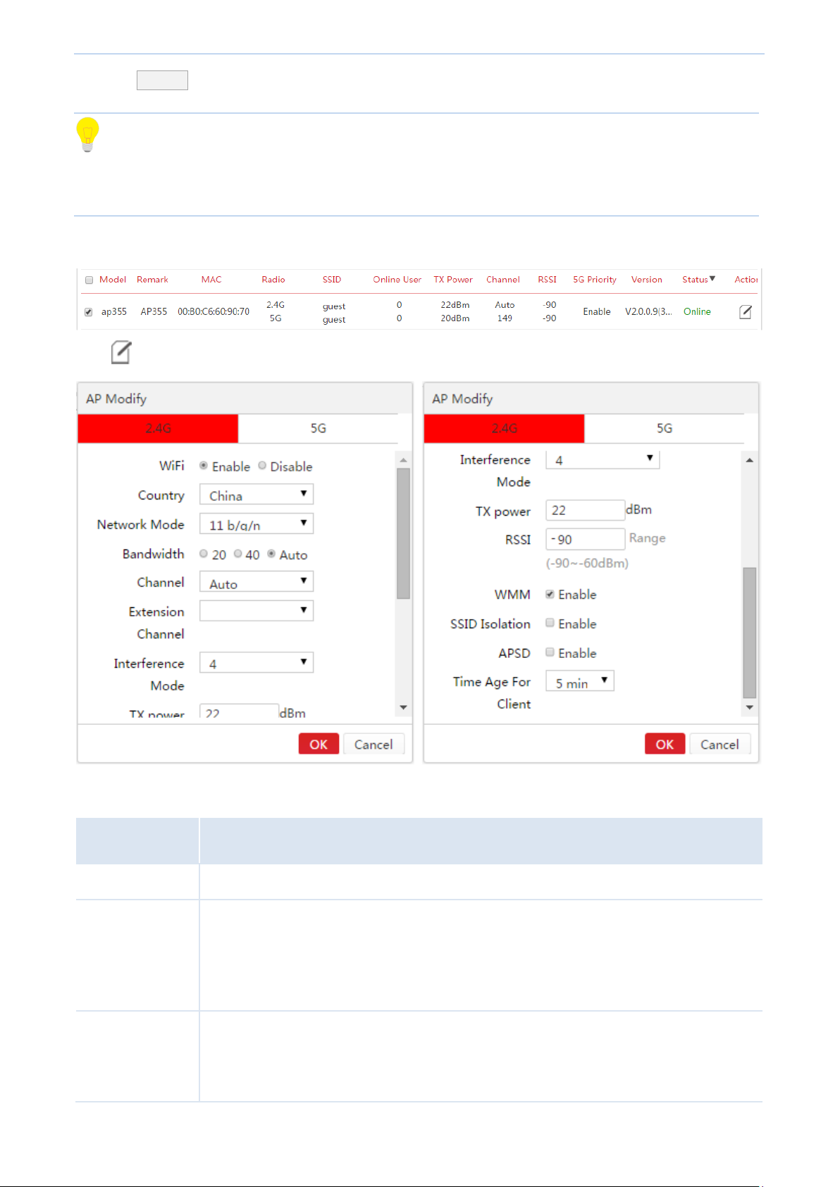
Item
Description
WiFi
Enable/disable AP's WIFI in each band.
Country
Countries apply for their own regulations to the allowable channels, allowed users and
maximum power levels within the frequency ranges. Consult your local authorities as these
regulations may be out of date as they are subject to change at any time. Most contries
allow the first eleven channels in the spectrum.
Network Mode
Select a Network Mode. 2.4G band includes 11b, 11g, 11b/g and 11b/g/n, while 5G band
includes 11a, 11ac and 11a/n. Descriptions are as follows.
11b: Works in 2.4G band and supports up to 11 Mbps.
2. Click Delete .
Tip
If the AP is offline, it keeps configuration delivered before. Users can still use their wireless network unless the AP
is restored to factory default.
Modify
Click on the right page to modify the AP's RF settings.
Parameter Description:
Page 63

Cloud AC Mode
11g: Works in 2.4G band and supports up to 54 Mbps.
11b/g: If you select this option, wireless clients supporting 802.11b or 802.11g can
connect to the WiFi.
11b/g/n: If you select this option, wireless clients supporting 802.11b, 802.11g or
802.11n can connect to the WiFi.
11a: Works in 5G band and supports up to 54 Mbps.
11ac: Works in 5G band and supports up to 1300Mbps. It is a newer standard that
uses wider channels, QAM and spatial streams for higher throughput
11a/n: Works in 5G band and supports up to 300Mbps, compatible with 11n.
Bandwidth
Select the wireless bandwidth.
20: 20MHZ channel bandwidth.
40: 40MHZ channel bandwidth.
80: 80MHZ channel bandwidth.
Auto: Automatically adjust the channel bandwidth to 20MHZ or 40MHZ based on
surrounding environment.
Channel
Select the wireless channel. Channel range differs from country and radio band.
Extension
Channel
When bandwidth is 40 or Auto, this is used to determine the channel range of AP.
Interference
Mode
Configure Interference mode. Value range: 0 ~ 4, the default value is "2".
0: Disable all interference immunity.
1: Enable the same frequency interference immunity.
2: Force to enable radio interference immunity.
3: Automatically enable radio interference immunity.
4: Automatically enable radio interference immunity and noise reduction.
Tip: Different AP models have different recommended interference mode. Please
contact IP-COM technical support engineer for help.
TX power
AP wireless transmit power, range: 1~99dBm. If this value is greater than the maximum
supported power of an AP, the latter takes effect after the policy is delivered.
RSSI
RSSI is short for Received Signal Strength Indication.
If a wireless client’s signal is lower than this value, the client can not connect to the AP,
which helps the client to connect to an AP with stronger signal.
WMM
Wi-Fi Multimedia (WMM) provides basic Quality of Service (QoS) features to IEEE 802.11
Page 64

Cloud AC Mode
networks. WMM prioritizes traffic according to four Access Categories (AC) - voice, video,
best effort, and background. However, it does not provide guaranteed throughput. It is
suitable for well defined applications that require QoS, such as Voice over IP (VoIP) on Wi-Fi
phones (VoWLAN).
SSID Isolation
Enable/Disable SSID isolation.
When enabled, wireless clients that connect to different SSID of the AP cannot
communicate with each other.
Page 65

Cloud AC Mode
APSD
APSD is short for Automatic Power Save Delivery. It is basically a feature mode that allows
your mobile devices to save more battery while connect to your WiFi network. By allowing
your mobile devices to enter standby or sleep mode, it conserves energy. It is only effective
when you enable WMM.
Time Age For
Client
After a client connects to the AP:
If there is no data transmission within the time period, AP will actively disconnect the
client.
If data transmission is detected within the time period, AP will recalculate the time age.
4.4 Captive Portal
Assume that you own a restaurant, and you want your customers to know more information about your
restaurant to help you promote your prducts. Then you can follow this part to create advertisements and deliver
them to SSID. In this way, your customers can get to know the advertisements after they successfully connect to
your SSID.
This section includes Create Ads, Ads Push, Global Settings, Create Account, and Voucher.
4.4.1 Create Ads
Tip
Configuration in this section also applies to 5.5.1 Create Ads in "Sub AC" mode.
To create a concrete advertisement, follow this section.
Click Captive Portal to get into the following page. By default, "Ads Push" function is disabled. You can click the
toggle ( to ) to enable this function. After you enable "Ads Push" function and don’t deliver any
other advertisement, the system will deliver the default advertisement, which name is “IP-COM WIFI Network
Solution” and authorization method is "No Password".
Page 66

Cloud AC Mode
Item
Description
Ad Name
Display the description of the advertisement.
Template
Display the advertisement template styles. Click Preview to preview the advertisement. Click Edit
to redesign the advertisement content.
Tip
The advertisement in "Using" status cannot be edited.
Status
Display whether the advertisement is using or not.
Click the button to create an advertisement. The access controller can create up to 10
advertisements, including 1 default advertisement and 9 custom advertisements.
Click the button to delete the selected unused advertisements.
Parameter Description:
Buttion Description:
To create an ad, click +Add to enter following the advertisement designing page, which consists of five parts,
includes "Select Ad Template", "Basic Information", "Ad Slide Image", "Navigation Settings" and "Authorization".
Details are as follows.
Page 67

Cloud AC Mode
1. Select the advertisement template
Template 3 only applies to "No Password" authorization method.
Template 1 and template 2 apply to "Portal" and "Voucher" authorization methods.
2. Set up the basic information of the advertisement
Page 68

Cloud AC Mode
Item
Description
Ad Name
Enter the name of the advertisement. The length of "Ad Name" can be up to 32 bytes.
Redirect Page:
Specify the redirect URL, which will appear automatically after the user has successfully
authorized.
The length of URL can be up to 128 bytes, supporting domain name or IP address.
Logo
Upload a business Logo image.
The image size cannot exceed 128 KB, and 96 * 48 pixel is recommended.
Copyright
Enter the copyright information of the advertisement.
Parameter's Help Info:
3. Add Slide Image Settings
In this section, you can add, edit, or delete the advertisement slide image.
To add slide images:
1. Click Add Image .
2. Enter the name of the slide image in the Ad Name box.
3. Click Select to upload the slide image.
(The ratio of the image is 16:9, and the image will adjust itself automatically.
The image size cannot exceed 128 KB.)
4. Click to save your settings in this section. (Click to clear the unsaved information.)
A slide image has successfully created
Page 69

Cloud AC Mode
5. Repeate 1~4 to create more slide images.
After you complete creating slide images, you can click to modify the added slide image, and click to
delete it.
4. Add Navigations
In this section, you can add, edit, or delete the navigation name.
To add Navigation:
1. Click Add Navigation .
2. Enter the name of navigation in the Ad Name box. (The length is up to 12 bytes.)
3. Click to save your settings in this section. (Click to clear the unsaved information.)
4. Repeat 1~3 to add more navigations.
After you complete creating navigations, you can click to modify the added slide image, and click to
delete it.
Page 70

Cloud AC Mode
5. Check to select the authorization method
This access controller supports "No Password", "Portal" and "Voucher" authorization methods.
Template 3 only applies to "No Password" authorization method.
Template 1 and template 2 apply to "Portal" and "Voucher" authorization methods.
No Password
If you select “No Password” authorization, users don’t need to enter any authorization information when
connecting to your WiFi. They just need to click the button Click to Access Internet after they view the
advertisement.
Tip:
"No Password" authorization method only applies to template 3.
"No Password" and other authorization methods cannot be selected at the same time.
Portal
If you select “Portal” authorization, users need to enter username and password to surf the Internet after they
connect to your WiFi and view the advertisement.
If using the "Portal" authorization, you need to create the "Portal" account and password on the access controller.
For details, please refer to 4.4.4 Create Account.
Voucher
If you select “Portal” authorization, users need to enter a voucher to surf the Internet after they connect to your
WiFi and view the advertisement.
Page 71

Cloud AC Mode
For the configuration of "Voucher", please refer to 4.4.5 Voucher.
Save your settings
Click OK to apply your settings.
Page 72

Cloud AC Mode
Click the button to add a new advertisement delivery policy.
Click the button to delete the selected advertisement delivery policies.
4.4.2 Ads Push
Tip
Configuration in this section also applies to 5.5.2 Ads Push in "Sub AC" mode.
After creating the advertisements, you need to deliver them to corresponding SSID and users. Click Captive
Portal Ads Push to get into the following page.
Button Description:
To deliver an ad:
1. Click +Add to enter the advertisement delivery page.
2. Select appropriate SSID, Terminal Type and Ad Name.
3. Click OK to apply your settings.
Page 73
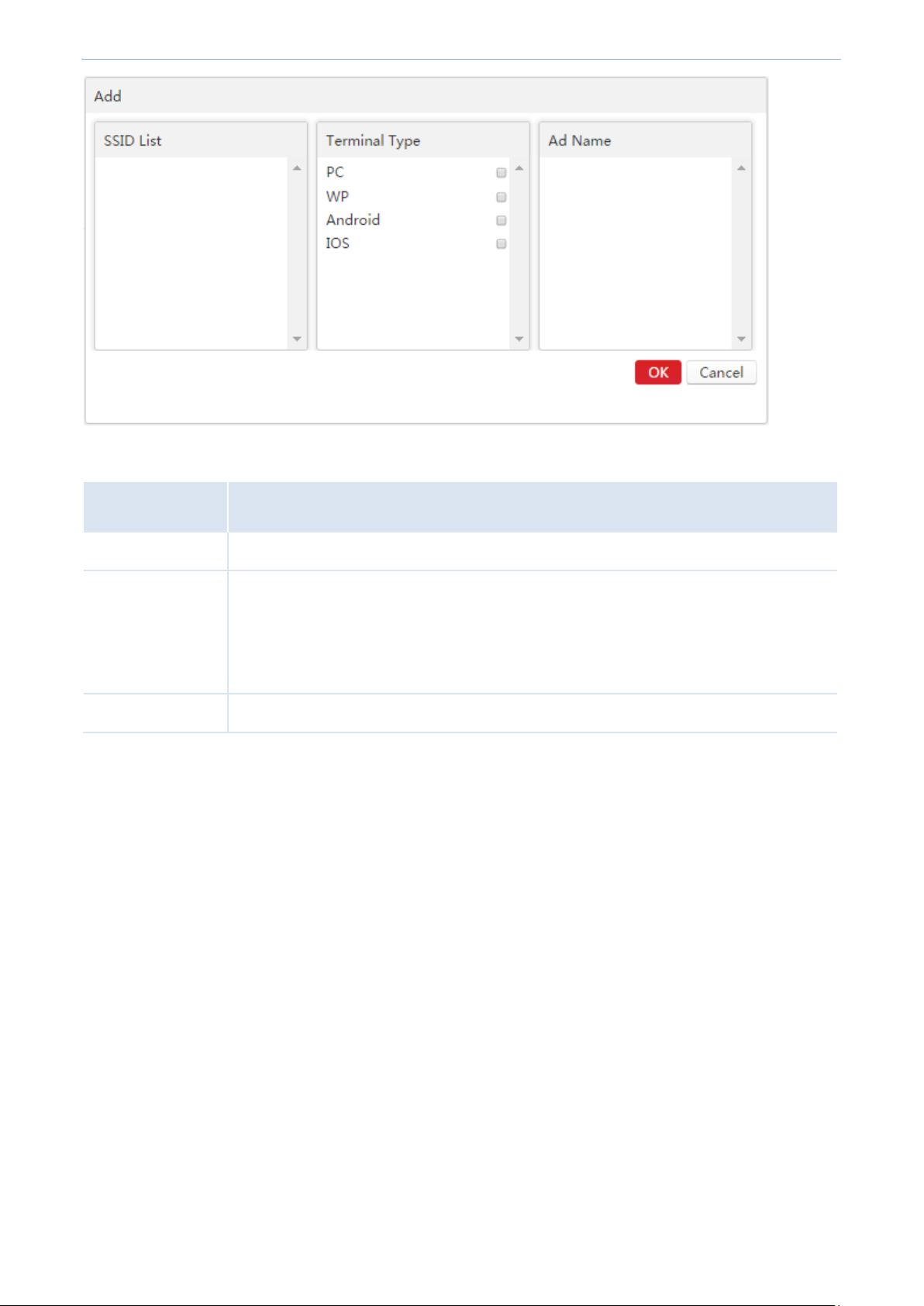
Cloud AC Mode
Item
Description
SSID List
Select the SSID you want to deliver the advertisement to.
Terminal Type
Select the terminal type to accept the advertisement. Among them, "PC" means the
operating system of a computer. "WP" is short for Windows Phone, which means the
mobile operating system from Microsoft. "Android" means the Android operating system.
"IOS" means the mobile operating system from Apple.
Ad Name
Select the advertisement name you want to deliver.
Parameter Description:
4.4.3 Global Settings
To set up the global parameters for authorization, click Captive PortalGlobal Settings to enter the following
page.
Page 74
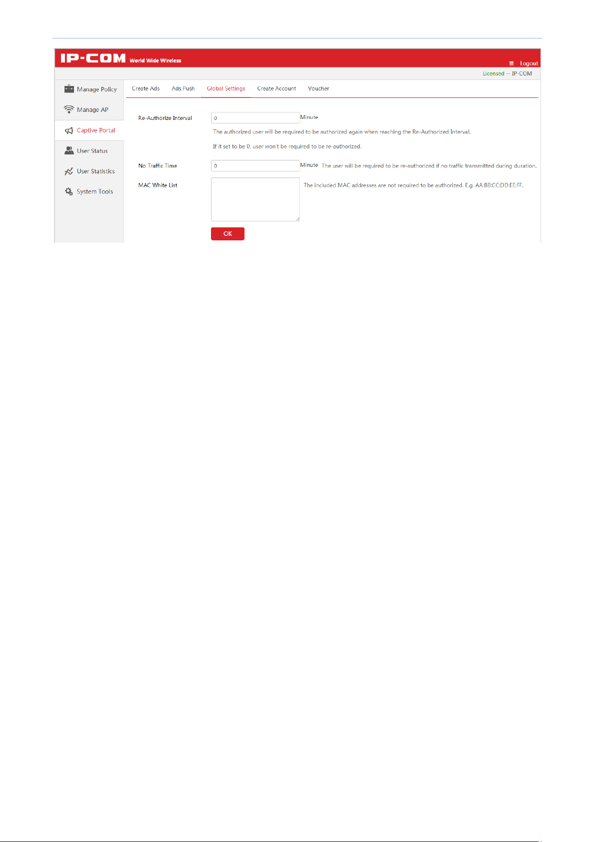
Cloud AC Mode
Page 75
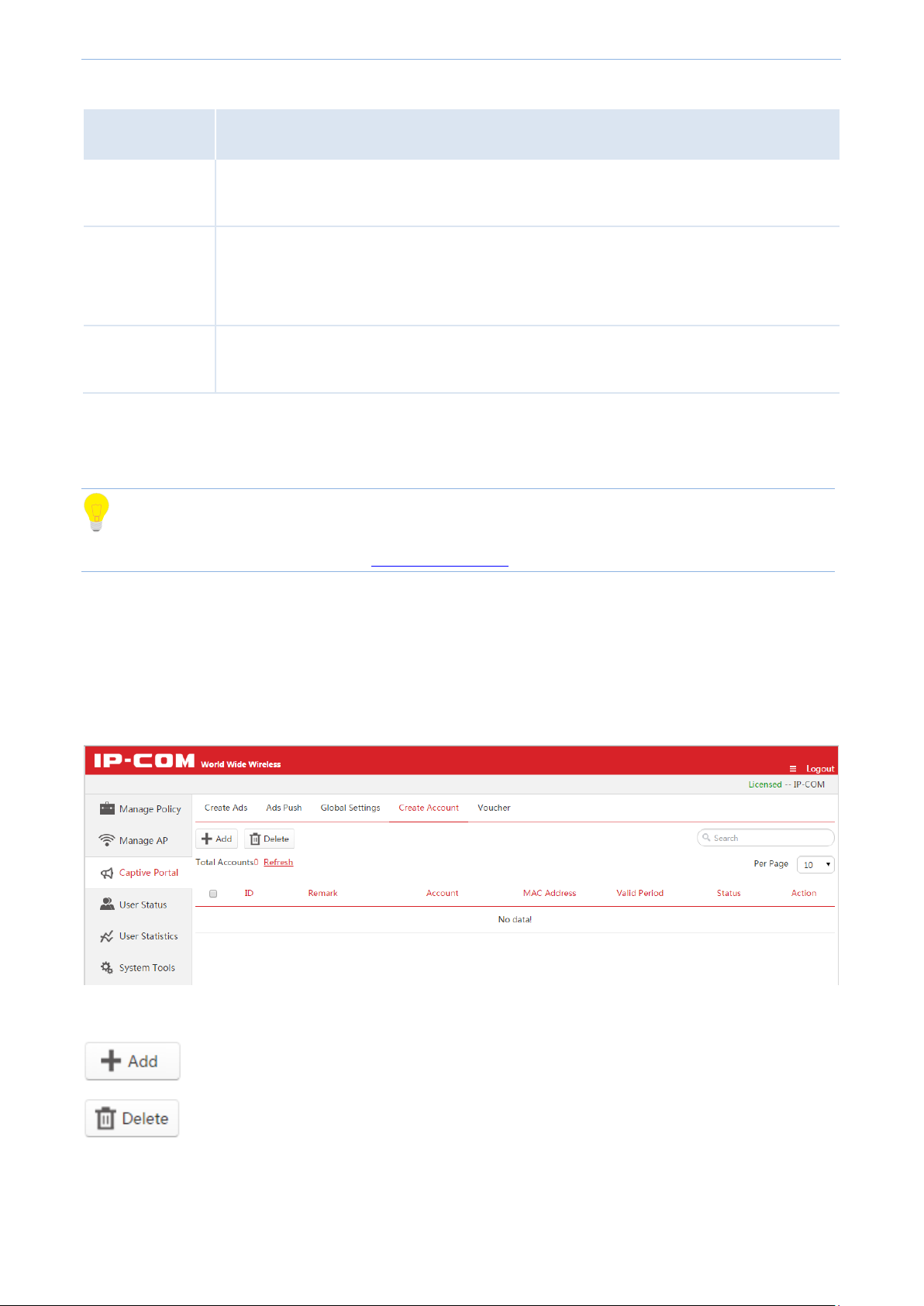
Cloud AC Mode
Item
Description
Re-Authorize
Interval
The user will be required to re-authorize when his authorized duration reaches this
specified time. The range is 20 ~ 360 minutes, and "0" means no need to re-authorize.
No Traffic Time
During this specified time, if the user has not transmitted any Internet data, he will be
required to re-authorize.
The range is 5 ~ 3600 minutes, and "0" means no need to re-authorize.
MAC White List
Enter the MAC address of devices which are not required to authorize. Up to 20 MAC
addresses are allowed, and each line supports one MAC address. E.g: AA:BB:CC:DD:EE:FF.
Click the button to create a new "Portal" account.
Click the button to delete the selected unused "Portal" accounts.
Parameter Description:
4.4.4 Create Account
Tip
Configuration in this section also applies to 5.5.4 Create Account in "Sub AC" mode.
If you select “Portal” authorization in your ad, you need to come to this section to create Portal accounts.
Click Captive Portal Create Account to get into the following page.
This access controller supports creating up to 150 "Portal" accounts.
Buttion Description:
Page 76

Cloud AC Mode
(Action)
Click the button to modify only the unused "Portal" accounts.
Item
Description
Account
Enter the account of the "Portal" authorization.
The length of the account is 2 ~ 15 characters, supporting numbers, letters and underlines.
Remark
Enter the description of the account.
Password
Enter the password of the "Portal" authorization. The length of the password is 2 ~ 15
characters, supporting numbers, letters and underlines.
Confirm Password
Enter the password again.
To create a portal account:
1. Click + Add to enter the "Create Account" page.
2. Set the account information.
3. Click Add to apply your settings.
Parameter Description:
Page 77

Cloud AC Mode
MAC Limit
Specify the MAC address of devices to be allowed to authorize with the account.
Only included MAC addresses are allowed to authorize with the account: If you select
this option, please enter the MAC addresses to be allowed to authorize with the
account. Up to 20 MAC addresses are allowed, and each line supports one MAC
address. E.g: AA:BB:CC:DD:EE:FF.
Allow multiple users to authorize with the account: If you select this option, please
enter the number of users to be allowed to authorize with the account.
Valid Period
Specify the effective time of the account.
Permanently: The account never expires.
Expired after: Enter the effective time of the account. When reaching the specified
time, the account will be deactivated automatically.
The format of time is 2016-05-10 00:00.
Page 78

Cloud AC Mode
Item
Description
Generate Voucher
Link
A seller can use the link to generate a unique voucher and print it to each customer to surf
the Internet.
Click the link to visit the voucher link page.
Click "Copy" to copy the link for future use. The seller can visit the voucher link page with
the the copied link.
Click "Update" to generate a new voucher link and the previous link will be unavailable.
4.4.5 Voucher
Tip
Configuration in this section also applies to 5.5.5 Voucher in "Sub AC" mode.
If you select “Voucher” authorization in your ad, you need to come to this section to configure the voucher
information.
Each voucher is a unique password. Users with a voucher can surf the Internet while others cannot.
Parameter Description:
Page 79
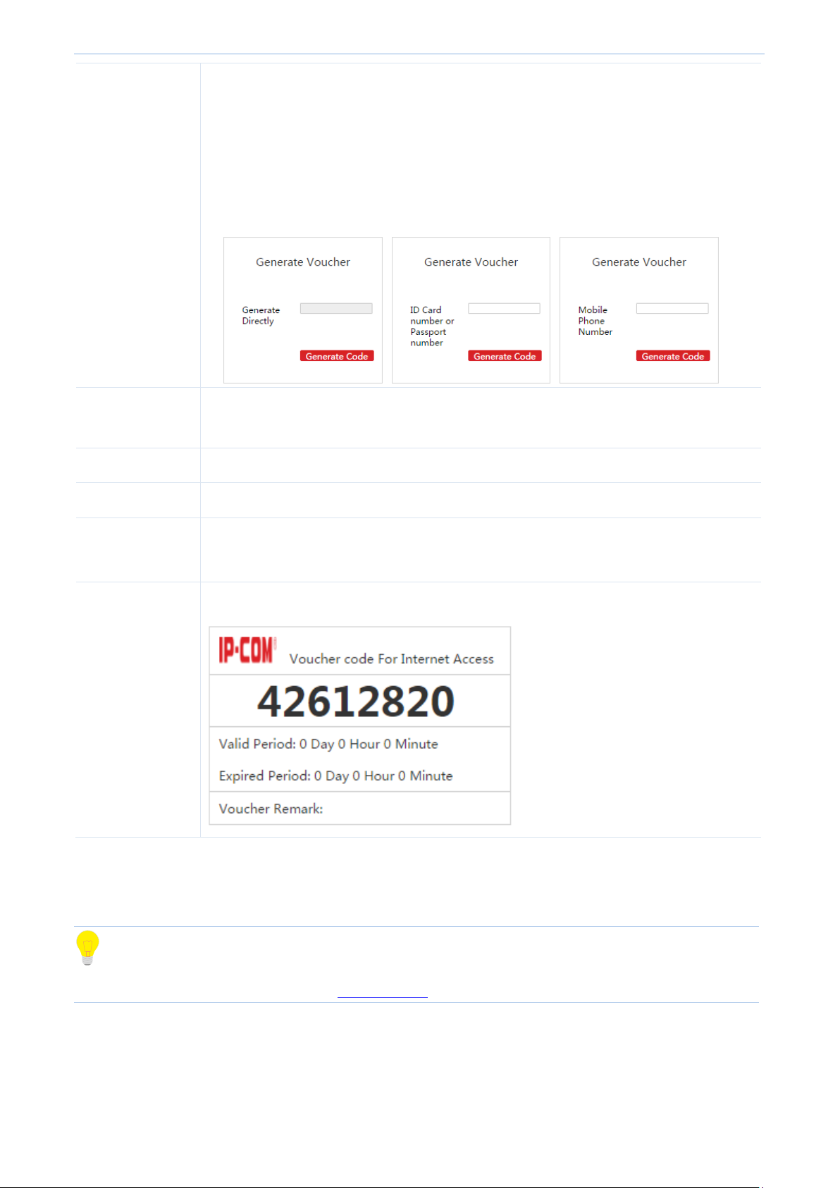
Cloud AC Mode
Generate Voucher
Mode
Directly: If you select this option, you can use the voucher link page to generate a
voucher directly, without offering any information.
ID Card number or Passport number: If you select this option, an ID card or passport
number is required to generate a voucher.
Mobile Phone Number: If you select this option, a mobile phone number is required
to generate a voucher.
Valid Period
Set up a valid period for each voucher. "0" means every voucher can be used without time
limit.
Expired Period
During the expired period, if the voucher is not used it will be unavailable.
Voucher Remark
The remark of the voucher. It is optional.
Logo For Voucher
Upload a Logo image, which will be displayed on the voucher.
It is recommended to upload the Logo of the seller.
Voucher Example
Display the voucher example.
4.5 User Status
Tip
Configuration in this section also applies to 5.6 User Status in “Sub AC" mode.
To check the information of authorized users or export the information to a directory, click User Status to enter
this page.
Page 80

Cloud AC Mode
Item
Description
Remark
Display AP remark. In order to manage different AP easily, it is recommended to
set up the Remark name as AP’s branch name or location.
Model
Display AP model.
SSID
Display the AP’s SSID which the user connects to.
Radio
Display the AP’s radio band which the user connects to.
Client's IP
Display the user device’s IP address.
Client's MAC
Display the User device's MAC address.
Terminal Type
Display the User device's operating system type.
Authorization
Display the User's authorization method.
Download
Display the user's total download traffic.
RSSI
RSSI is short for Received Signal Strength Indication.
If a wireless client’s signal is lower than AP’s specified value, the client can not
connect to the AP, which helps the client to connect to an AP with stronger signal.
The RSSI here displays the user’s RSSI.
Online Time
Display the authorized online period of the user.
Status
Display whether the user is online or offline.
Online: The user has successfully authorized to the AP currently.
Offline: The user does not authorize to the AP currently.
To export this page’s information into an appropriate directory, click Export on the page and then follow
on-screen instructions. The exported file is in the format Filename.xls.
If a warning message appears when you open the exported file, click Yes(Y) .
Parameter Description:
Page 81

Cloud AC Mode
4.6 User Statistics
Tip
Configuration in this section also applies to 5.7 User Statistics in "Sub AC" mode.
4.6.1 User Statistics
Tip
Configuration in this section also applies to 6.6.1 User Statisticsin "Root AC" mode.
To view the statistics result of authorized users, click User Statistics to enter the following page.
Online Users
This section displays the amount of authorized online users of today, yesterday and this month and the amount
of new authorized users of today.
Page 82

Cloud AC Mode
User Statistics
This section displays the amount of authorized users at each moment in the current day.
Authorization/Terminal/Authorize Times
Authorization: Display the ratio of different authorization method in the current month.
Terminal: Display the ratio of different authorized terminal or operating system in the current month.
Authorize Times: Display the ratio of different authorization time in the current month.
Page 83

Cloud AC Mode
Export the detail information of authorized users in this month.
Delete all the user information which corresponds to offline APs.
Item
Description
Account
Display the authorization account and its authorization method of the user.
Remark
Display the description of AP which the user has connected to.
IP Address
Display the IP address that the user has obtained.
MAC Address
Display the MAC address of the user.
Terminal Type
Display the terminal type or operating system of the user.
Total Download
Display the total download traffic of the user.
Authorized
Time
Display the authorized time of the user for the first time.
Online Time
Display the total amount of Internet time of the user.
Connected
Times
Display the amount of times the user has connected to the AP.
Status
Display the instant Internet connection status of the user.
4.6.2 Authorized User
To view the the detail information of authorized users or export the information to a directory, click User
StatisticsAuthorized User to enter the following page.
Buttion Description:
Parameter Description:
Page 84

Cloud AC Mode
4.7 System tools
4.7.1 System Status
Tip
Configuration in this section also applies to 5.8.1 System Status in "Sub AC" mode.
To check the access controller's Interface status, system status and the Network Information, go to System Tools
System Status.
Page 85

Cloud AC Mode
Item
Description
Managed APs
Display the amount of online APs which can be managed by the AC currently.
Offline APs
Display the amount of offline APs which can not be managed by the AC currently.
Connected clients
Display the amount of online users that connect to online APs.
Run Time
Display the duration of time that the access controller has been running from last reboot.
Run time will be re-counted when the access controller reboots.
CPU Usage
Display the percentage of used CPU space of the AC.
Memory Usage
Display the percentage of used memory space of the AC.
Interface Status
This section displays the connection status of each physical interface of the access controller.
System Status
This section displays the the status of following parameters.
Page 86

Cloud AC Mode
Network Information
This section displays the access controller's LAN IP address/subnet mask, MAC address, and the Firmware
Version.
4.7.2 Network Settings
To set up IP information to connect to Internet, and set up the VLAN information, click System Tools Network
Setting to enter the following page.
Page 87

Cloud AC Mode
Item
Description
IP Address
Set up the AC’s IP Address. In order to connect to Internet, in general, this IP address
and the uplink router’s LAN IP address should be on the same IP segment.
Subnet Mask
Set up the AC’s subnet mask. The default value is 255.255.255.0.
Gateway
Set up the AC’s default gateway. In order to connect to Internet, in general, it is set to
the uplink router’s LAN IP address.
Preferred DNS
Set up the AC’s DNS server address. It is generally set to the uplink router’s LAN IP
address.
Alternate DNS
Optional: When the Preferrd DNS address goes wrong, the Alternate DNS address will
take the place of Preferred DNS address.
LAN Settings
To make your AC connect to Internet, you need enter the correct IP address, subnet mask, gateway and
Preferred/Alternate DNS in this section.
Parameter Description:
VLAN Settings
Tip
It is not recommended to configure VLAN Settings in the "Cloud AC" mode.
If you need to configure VLAN settings in "Cloud AC" mode, please refer to VLAN Settings in "Sub AC" mode.
Page 88

Cloud AC Mode
4.7.3 Maintain
Tip
Configuration in this section also applies to 5.8.4 Maintain in"Sub AC" mode.
To configure License, System Mode, User Management, and Maintenance, click System Tools Maintain to
enter this page.
License
By default, the AC can manage up to 256 APs. If you want the access controller to manage more APs
(management of up to 512 APs), please contact IP-COM technical support engineer to obtain a corresponding
license file.
Page 89

Cloud AC Mode
Item
Description
Device Name
In order to locate the AC easily, it is recommended to set up the Device Name as AC’s
location.
Working Mode
Select the working mode of the access controller. For details, please refer to 5.1 Sub AC
Mode Introduction, 6.1 Root AC Mode Introduction and 4.1 Cloud AC Mode Introduction.
Root AC Address
In "Sub AC" mode, your are required to enter the public IP address or binded domain
name of the gateway which connects the Root AC.
To update your license:
1. Contact IP-COM technical support engineer to obtain a license file.
2. Log in to the AC’s Web UI, go to System Tools Maintain License, click Import Licensed File .
3. In the pop-up dialog box, locate and select the license file and click Open(O) .
4. In the pop-up dialog box, click OK .
You license completes updating.
System mode
Tip
Configuration in this section also applies to 6.4 System mode in "Root AC" mode.
The access controller supports three working modes: Sub AC, Root AC and cloud AC, among which you can
choose easily according to the networking environment.
Parameter Description:
Page 90

Cloud AC Mode
Manage Port
When Root AC needs to manage Sub ACs, the “Manage Port” of Sub ACs and Root AC
must be the same.
When Cloud AC needs to manage Cloud APs, the “Manage Port” Cloud APs and Cloud AC
must be the same.
Firmware Upgrade
Port
When Root AC needs to upgrade a firmware for Sub ACs, the “Firmware Upgrade Port” of
Sub ACs and Root AC must be the same.
When Cloud AC needs to upgrade a firmware for Cloud APs, the “Firmware Upgrade Port”
of Cloud APs and Cloud AC must be the same.
User Management
Tip
Configuration in this section also applies to 6.7.3 User management in"Root AC" mode.
Here, you can modify the login user name and password to prevent rogue users from entering the Web UI to
change settings. Both user name and password’s length range is 3~32 characters, supportting letters
(case-sensitive), numbers and underscores.
After changing user name and password successfully, the Web UI will automatically be logged out. Please enter
the new user name and password to login again.
Page 91

Cloud AC Mode
Maintenance
Tip
Configuration in this section also applies to 6.7.2 Device maintenance in"Root AC" mode.
Here, you can upgrade, reboot, backup/restore and reset your access controller.
Firmware Upgrade
When the access controller works abnormally in some circumstances, please visit http://www.IP-com.com.cn to
search for released software to solve this problem.
Note
When an AC firmware is upgrading, please DO NOT power off the AC or it may cause damage to the AC! If a
sudden power off occurs, please upgrade again. If you cannot log in to AC's Web UI after a sudden power off,
please contact our technical support engineer.
To upgrade a firmware for AC:
1. Go to http://www.ip-com.com.cn to download the AC’s firmware to an appropriate directory.
2. Log in to the AC's Web UI and go to System Tools Maintain Maintenance Firmware Upgrade.
3. Click Select a file to select and upload the AC’s firmware from the appropriate directory.
4. In the pop-up dialog box, click OK to upgrade the firmware.
5. Waite until the progress bar runs to 100%.
You can go to System Tools System Status Network Information Firmware Version to check whether the
upgrade is successful.
Page 92

Cloud AC Mode
Reboot
To make some settings take effect or to enhance the ACs performance, please reboot the AC.
Click Reboot to reboot the AC.
Backup Configuration
It is recommended to backup the configuration after you make a lot of configurations.
Click Backup and follow the on-screen instruction to complete the backup process.
Page 93

Cloud AC Mode
Restore Configuration
If you need configure multiple ACs to the same configuration, or if your AC’s performance goes down because of
improper configuration, you can restore your AC to a previous working configuration.
To restore configurations:
1. Click Select a file .
2. In the pop-up dialog box, select the saved backup configuration file and click Open(O) .
3. In the pop-up dialog box, click OK to restore the configuration.
4. Wait until the progress bar finishes.
Page 94
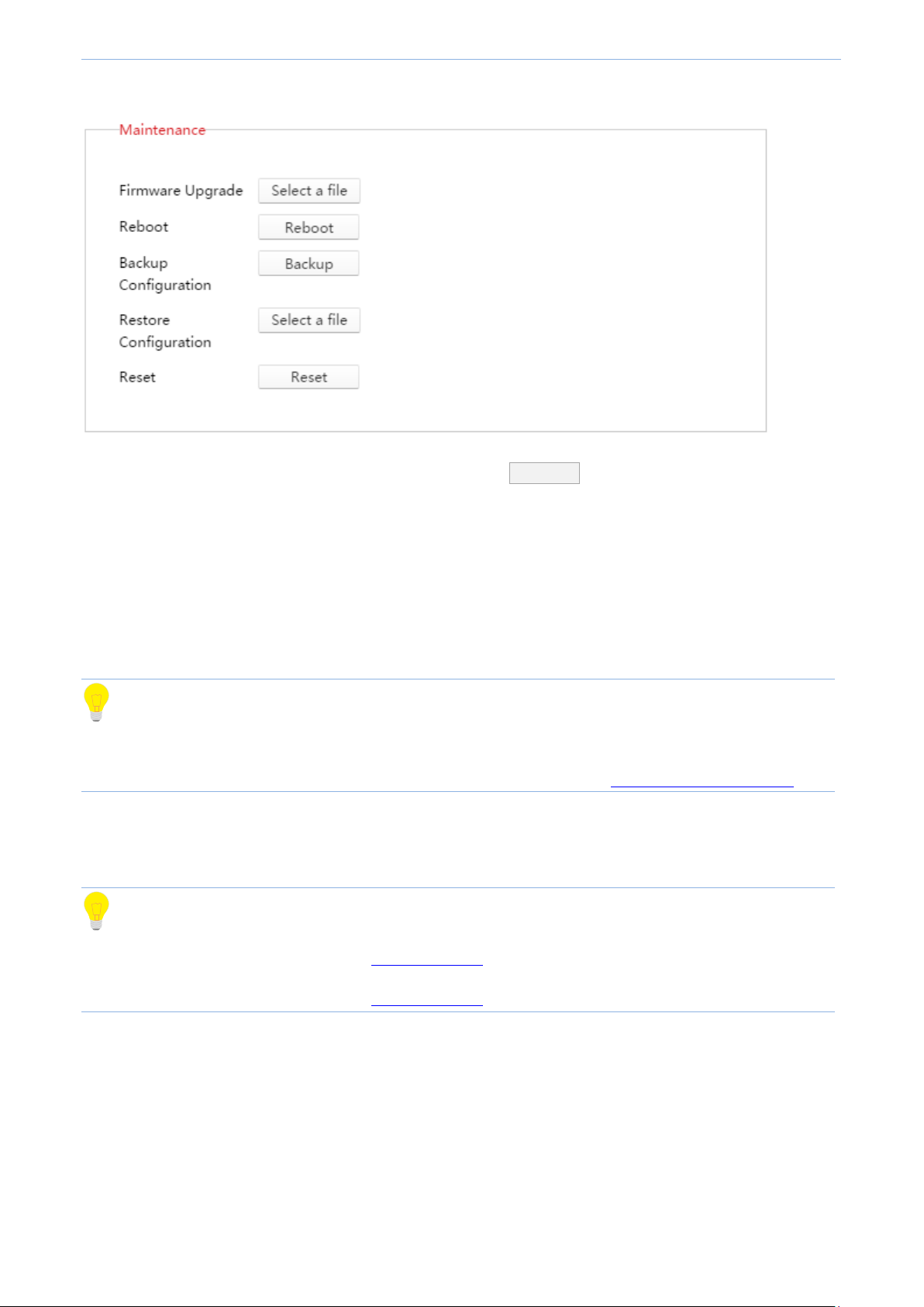
Cloud AC Mode
Reset
If you want to clear all configurations of the AC, please click Reset in the above picture and follow the
on-screen instructions to restore the AC to factory default.
Besides, if you forget the AC's login username or password, you can restore the AC to factory default by pressing
RESET button in the front panel of the device, doing as follows:
1. When the AC is powered on, use a needle to press the RESET button for 7 seconds.
2. Wait for about 2 minutes, the AC will complete its resetting process.
Tip
After restoring to factory default, the AC works in "Sub AC" mode. Login IP address is "192.168.10.1". Both login
user name and password are"admin". For other default settings, please refer to B Default parameter setting.
4.7.4 Date&Time
Tip
Configuration in this section also applies to 5.8.5 Date&Time in "Sub AC" mode.
Configuration in this section also applies to 6.7.4 Date&Time in"Root AC" mode.
To set your access controller's system time and Web Expired time, go to System tools Date&Time.
Page 95
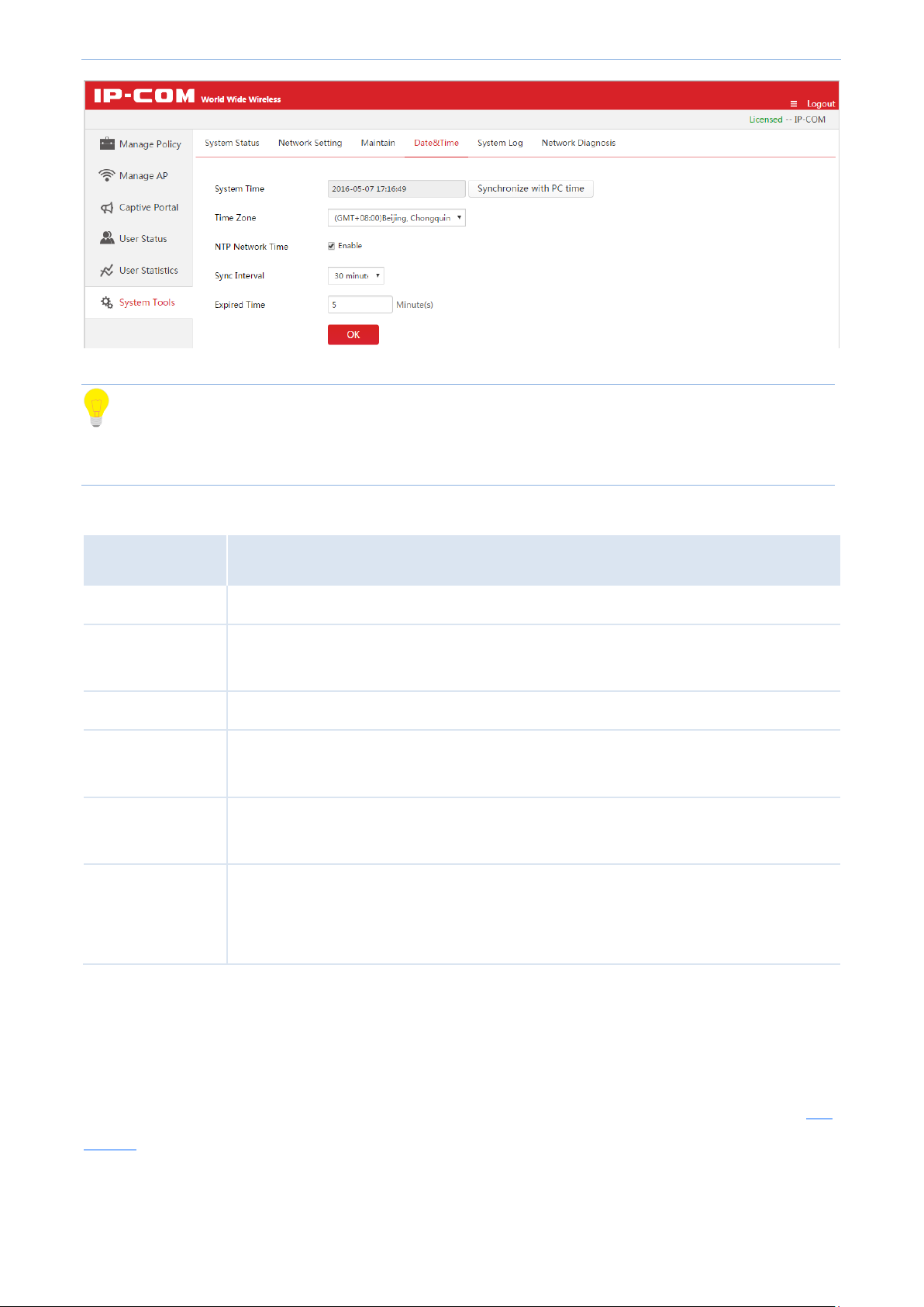
Cloud AC Mode
Item
Description
System time
Display the AC's current time.
Synchronize with
PC time
When clicked Synchronize with PC time, the AC will synchronize time with your computer.
And you must ensure that your PC’s time is correct.
Time Zone
Select GMT time zone where the AC is deployed.
NTP network time
When enabled, the AC’s time will synchronize with Internet time server periodically at a
specific time interval.
Sync Interval
Select how often the AC will synchronize with Internet time server. Default option is 30
minutes.
Expired Time
If the user has no operation in the Web UI within the expired time, the system will
automatically be logged out itself.
Range: 5~60 minutes. Default value: 5 minutes.
Tip
Time will be lost if the AC is powered off. But if you enable “NTP Network Time”, the AC will synchronize time
with Internet after reboot. And then time-related functions will perform correctly.
Parameter Description:
NTP Network Time
When enabled NTP Network Time function, the access controller will synchronize with Internet time server
periodically at a specific time interval.
NTP Network Time requires a successful Internet connection. (To connect to Internet, please refer to LAN
Settings)
Page 96

Cloud AC Mode
To configure NTP Network Time:
1. Choose standard GMT Time Zone where your AC is deployed, e.g. "(GMT-10:00) Hawaii ".
2. Check to enable the NTP Network Time function.
3. Select a Synchronization Interval. It is recommended to keep for "30 minutes".
4. Click OK .
Synchronize with PC time
When clicked Synchronize with PC time, the AC will synchronize time with your computer. And you must ensure
that your PC’s time is correct.
To synchronize with PC time:
1. Click Synchronize with PC time .
2. Do not check NTP Network Time to disable NTP Network Time function.
3. Click OK .
Page 97
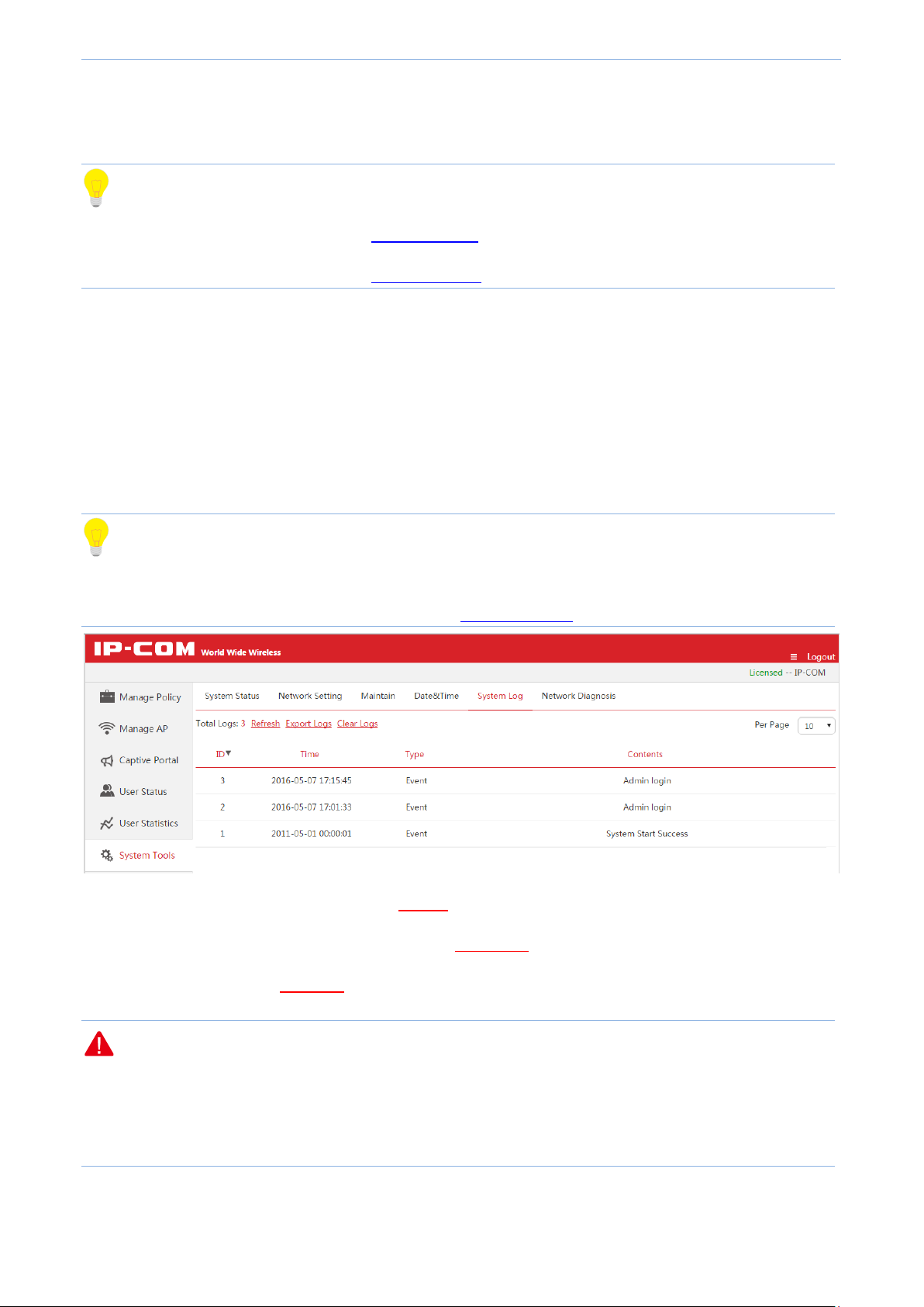
Cloud AC Mode
4.7.5 System log
Tip
Configuration in this section also applies to 5.8.6 System log in “Sub AC" mode.
Configuration in this section also applies to 6.7.5 System Log in"Root AC" mode.
The AC’s log system makes records of AP connections and alert information. You can sort logs by clicking the
downward or upword triangle in each field shown in the list, depending on whether you want to descendly or
ascendly view logs. The latest log will be displayed first. The system can keep up to 3000 pieces of logs. Oldest
logs will be deleted to leave space for newest ones.
Click System Tools System Log to get into this page.
Tip
In order to better monitor your network status and problem, please make sure the access controller's time is
correct. To configure the correct time for the AC, refer to 4.7.4 Date&Time.
To check the latest log information, please click Refresh.
To save your logs to a appropriate directory, please click Export logs.
To delete all logs, please click Clear logs.
Note
All the system logs will be lost if you reboot your AC.
The configurations including powering on AC, resetting AC to factory default or upgrading a firmware for AC,
will make the AC reboot.
Page 87
Page 98

Cloud AC Mode
4.7.6 Network Diagnosis
Tip
Configuration in this section also applies to 5.8.7 Network Diagnosis in "Sub AC" mode.
Configuration in this section also applies to 6.7.6 Network Diagnosis in "Root AC" mode.
To detect network connection status of the AC, click System Tools Network Diagnosis to enter this page.
This access controller provides Ping and Traceroute diagnosis tools.
Ping
Ping is a commonly used diagnosis and troubleshooting command. It consists of ICMP request and response
packets. If the network works normally, the target device will return response packets.
Page 88
Page 99

Cloud AC Mode
Item
Description
Destination
IP/Domain
Set the target IP address or domain name, e.g. www.google.cn.
Packet Number
Set the number of request packets.
Packet Size
Set the size of request packets.
Parameter Description:
Page 89
Page 100

Cloud AC Mode
Traceroute
Traceroute is a computer network diagnostic tool for displaying the route (path) and measuring transit delays
of packets across an Internet Protocol (IP) network.
Page 90
 Loading...