

Page 1
MOTOSPAZZATRICE/FLOORSWEEPER/BALAYEUSE/
MOTORKEHRMASCHINE/MOTOBARREDORAS/VEEGMACHINE/
VARREDORAMECÂNICA
1010S-JET1000S-1020S
MANUALED'USO/OPERATOR'SMANUAL/
MANUELD'INSTRUCTIONS/BEDIENUNGSANLEITUNG/
MANUALDEINSTRUCCIONES/GEBRUIKERSHANDLEIDING/
MANUALDEUTILIZAÇÃO/
Page 2
ITALIANO (Istruzioni originali)
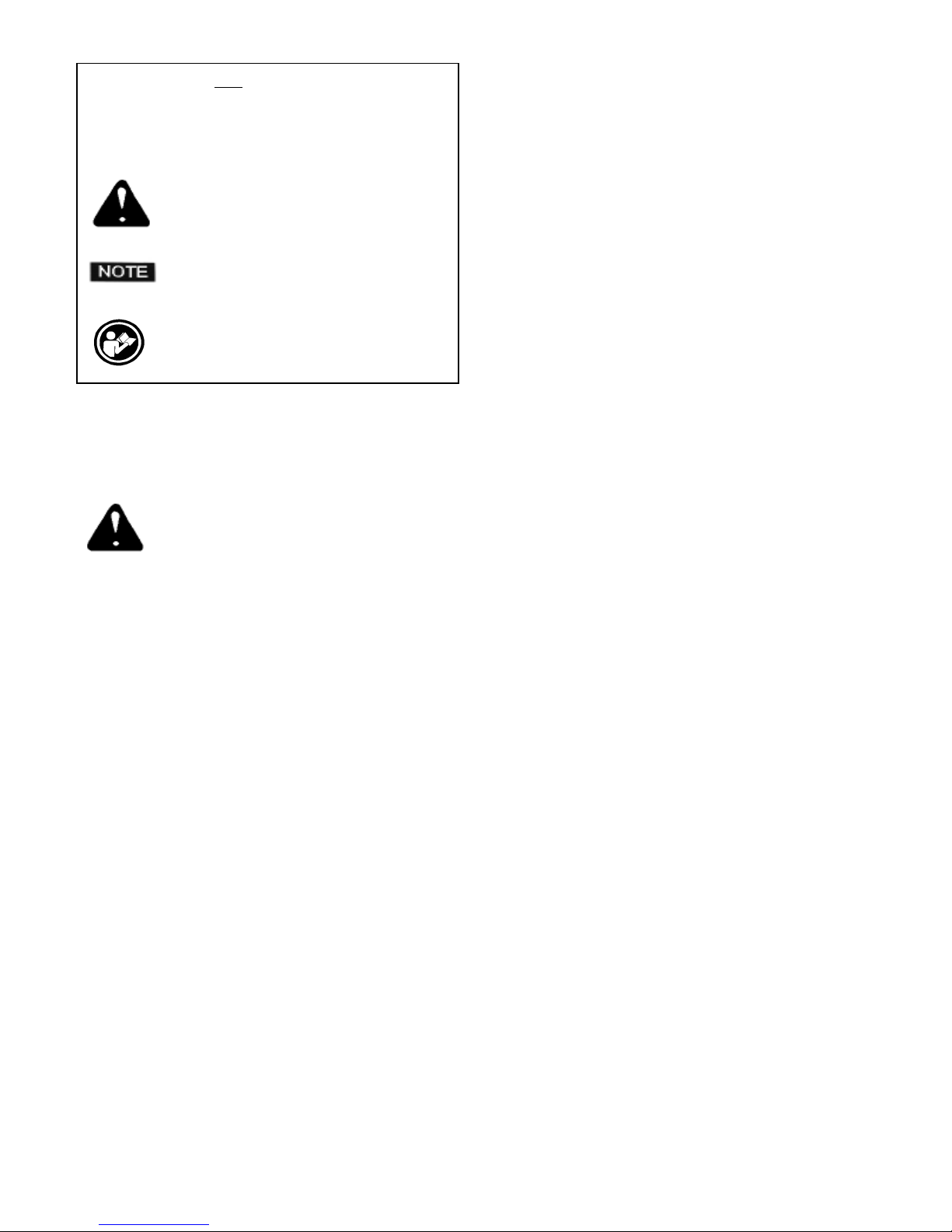
Pag. 1
Page 3
CONVENZIONI E LEGENDA
Eventuali indicazioni DESTRA e SINISTRA ORARIO e
ANTIORARIO presenti in questo libretto,si intendono sempre
riferite al senso di avanzamento della macchina.
ATTENZIONE:La macchina e dotata di un dispositivo di presenza
il quale consente l'accensione della stessa solo se l'operatore si
trova nella corretta posizione di lavoro.
Il dispositivo arresta la macchina nel caso in cui l'operatore si alzi
dal sedile.
I paragrafi preceduti da questo simbolo trattano di
argomenti che,se non rispettati, possono arrecare
danni alla macchina.
I paragrafi preceduti da questo simbolo trattano di
argomenti che,se non rispettati,possono provocare
lesioni.
I paragrafi preceduti da questo simbolo trattano di
argomenti che devono essere letti molto attenta-
mente
Usate questo manuale per imparare le caratteristiche della macchina e per comprendere come meglio sfruttarle.
Tutti i paragrafi riportati nel seguente capitolo
possono provocare, se non rispettati danni a perso
ne e/o cose.
SI RACCOMANDA DI TENERE LA MACCHINA
FUORI DALLA PORTATA DI BAMBINI.
IMPORTANTE: Il costruttore NON può essere considerato
responsabile di danni provocati dalla macchina qualora questa
venga usata in maniera non conforme all'uso.
Se il livello dell'olio del motore dovesse scendere al di sotto del
minimo consentito,un sistema di sicurezza ferma automaticanente
il motore.
Non lavare la mai la macchina utilizzando un getto d'acqua.
La macchina non deve essere usata per l'aspirazione di sostanze
tossiche.
E' vietato usare la macchina su superfici con pendenza superiore
al 12%.
Utilizzare la macchina esclusivamente in luoghi aperti ed areati.
La macchina puo' lavorare solamente in luoghi illuminati.
Nel caso in cui la macchina venga usata in un luogo dove esiste il
pericolo di caduta di piccoli oggetti,l'operatore deve indossare il
casco di protezione.
Non utilizzare la macchina per raccogliere cavi, reggette, filo di ferro,
od altro materiale simile.
E' vietato usare la macchina in prossimità di cavi, fili, o altro materiale
simile.
Non avviare la macchina con il pedale di selezione della direzione
premuto, la sua partenza improvvisa potrebbe causare danni a
cose e/o a persone.
La macchina NON PUO' e NON DEVE ESSERE trainata.
La macchina NON DEVE subire nessun tipo di manomissione,in
caso contrario il costruttore declina ogni responsabilità sul funzionamento corretto o su eventuali danni provocati a coseo a persone
dalla macchina stessa
La macchina deve essere utilizzata solamente da personale autorizzato ed addestrato all'uso.A tale proposito si ricorda che è fatto
ASSOLUTO DIVIETO di
- Trasportare persone. Conducente escluso.
- Entrare in contatto con parti in movimento della macchina.
- Togliere i carter di protezione a macchina avviata.
- Abbandonare la macchina accesa.
E' indispensabile portare un abbigliamento adeguato al tipo di
lavoro che si sta svolgendo.
Se si sta operando in una zona molto polverosa, per es. cementificio,
segheria cantieri,ecc..,è consigliabile usare:
- mascherina.
- occhiali di protezione.
- guanti.
NON ABBANDONARE mai la macchina con la chiave di accensione inserita nel quadro comandi.
E’ VIETATO L’UTILIZZO E LO STOCCAGGIO IN AMBIENTI CON ATMOSFERA POTENZIALMENTE
ESPLOSIVA
ITALIANO (Istruzioni originali)
Pag. 2
Page 4
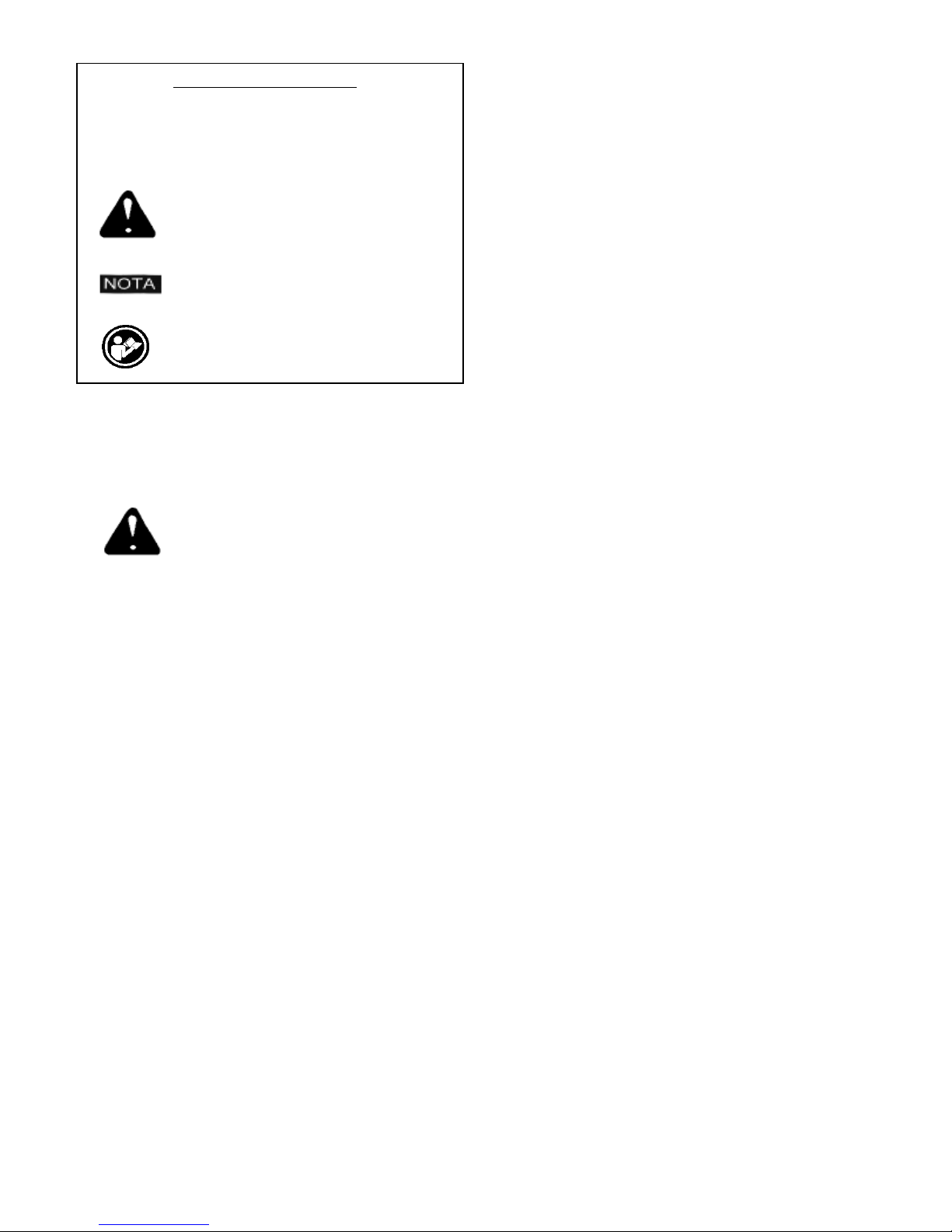
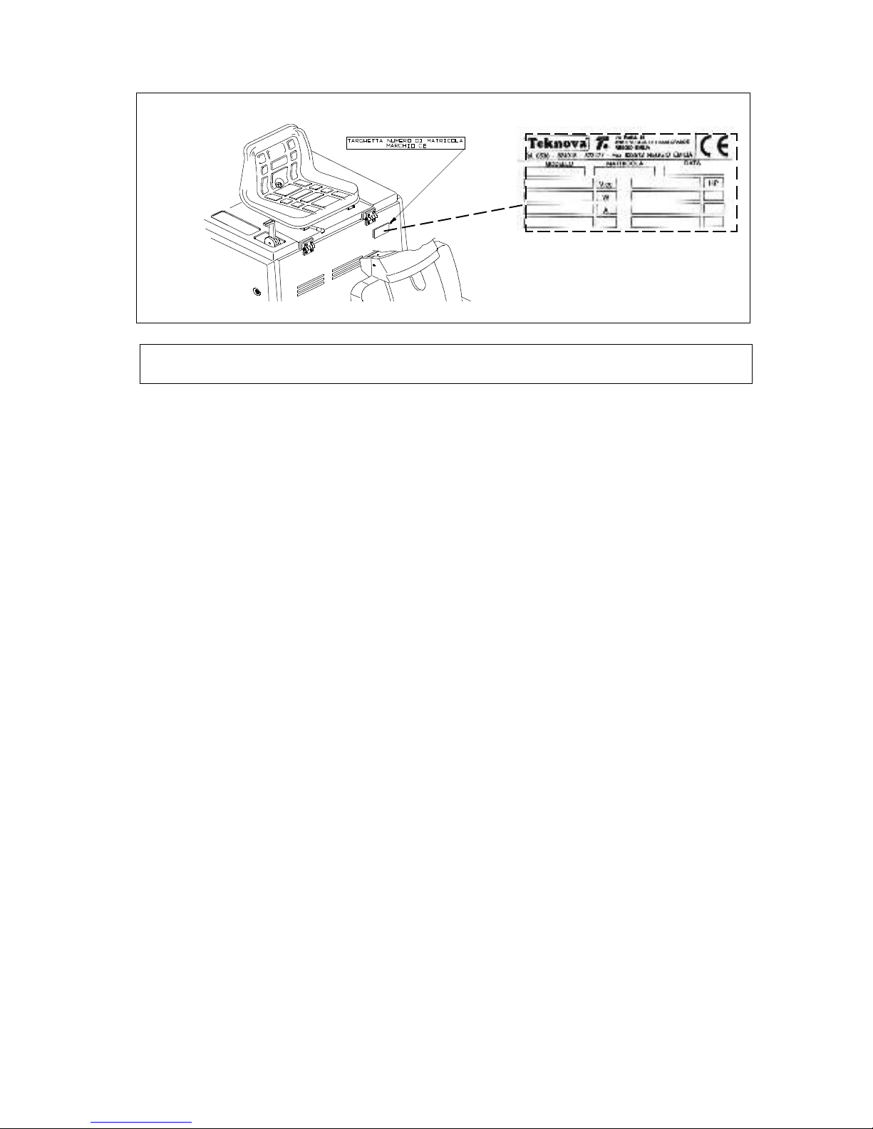
2.2 MATRICOLA MARCHIO CE
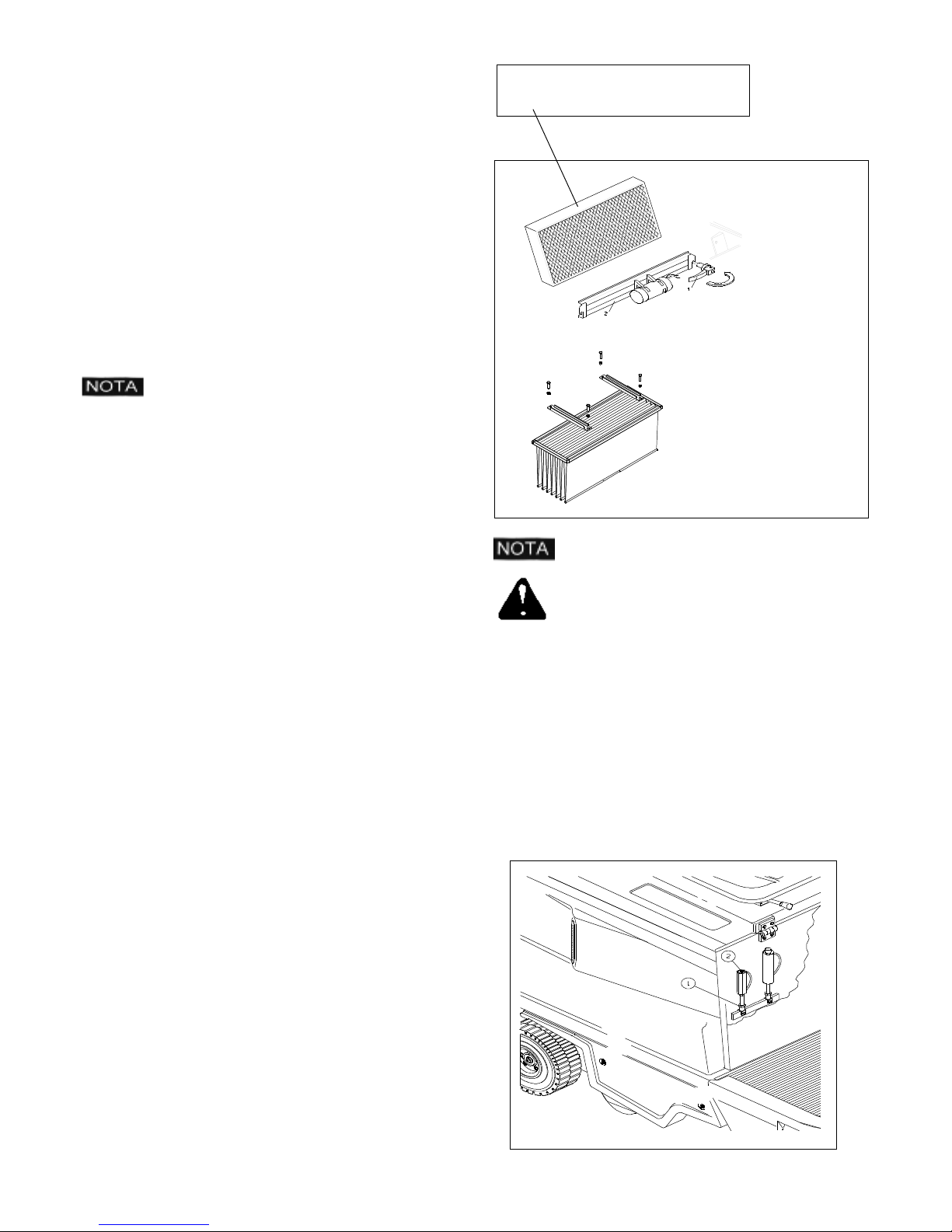
Accertarsi che la macchina sia provvista di targhetta riportante il numero di matricola, ed il marchio CE posizionata come da figura.In
caso contrario avvisare subito il rivenditore.
Serial number - CE marking
2.3 DATI TECNICI
2.3 TECHNICAL FEATURES
Tensione principale Main Power 12 V
Potenza massima totale installata Maximum installed power 5. 5 Hp
Trasmissione su 1 ruota Transmission Monoruota - One-wheel
Velocità d'avanzamento Forward gear speed 0 - 6,2 Km/h
Velocità in retromarcia Reverse gear speed 0 - 4,6 Km/h
Larghezza di pulizia con spazzola centrale Cleaning width with main brush 700 mm
Larghezza di pulizia con spazzola laterale Cleaning width with side brush 900 mm
Larghezza di pulizia con doppia spazzola laterale Cleaning width with double side brush 1100 mm
Capacità contenitore rifiuti Capacity of the waste bin 65 Lt
Filtro a pannello Panel filter 4 m²
Produttività Productivity 3800 - 5600 m²/h
Peso Weight 290 Kg
Caratteristica batteria Battery 12V / 45Ah
Motovibratore Motovibrator 12V DC 90W
Pendenza massima di utilizzo Max. sloping surface allowed 12%
Pompa a portata variabile Pump 0 - 10 cc
Motore idraulico Hydraulic motor 98 Cm³/rpm
Pressione Sonora LpA Sound Pressure LpA 76 dB
POTENZA SONORA MISURATA LWA MEASURED SOUND POWER LWA 90 dB
POTENZA SONORA GARANTITA LWA,g GUARANTEED SOUND POWER LWA,g 91 dB
Vibrazioni mano HAV Hand vibration HAV 2,3 [m/sec
(incertezze della misura) k (measurement uncertainty) k 1,2 [m/sec
Vibrazioni corpo HBV Body vibration HBV 0,8 [m/sec
(incertezze della misura) k (measurement uncertainty) k 0,4 [m/sec
ITALIANO (Istruzioni originali)
Pag. 3
2
]
2
]
2
]
2
]
Page 5
3.1 - INTRODUZIONE
Il presente libretto di istruzioni, ha lo scopo di servire da guida e
contiene le informazioni pratiche per la sicurezza,il funzionamento,la
registrazione e la manutenzione della macchina.La macchina è stata
progettata e costruita per assicurare il massimo delle prestazioni del
comfort e della facilità di lavoro in una grande varietà di
condizioni.Prima della consegna la macchina è stata controllata in
fabbrica e dal nostro conces-sionario per garantire che Vi venga
consegnata in perfette condizioni.Per mantenere la macchina in tali
condizioni e assicurare un lavoro senza problemi,è indispensabile
che le operazioni di manutenzione periodica indicate in questo
manuale siano eseguite.
4.2 - PRECAUZIONI DA PRENDERE PRIMA DI METTERE IN FUNZIONE LA MACCHINA:
Per facilitarne il trasporto,la spazzola/e laterale/i non è montata
/e nella posizione prevista per il funzionamento della
macchina.Procedere al montaggio come descritto nel paragrafo
4.3.
. Riempire il serbatoio benzina con benzina VERDE senza piombo.
. Controllare il livello dell'olio del motore.
3.2 - CAMPO DI UTILIZZO
La macchina è destinata ESCLUSIVAMENTE alla pulizia di pavimenti tramite spazzolatura ed aspirazione di superfici asciutte.Ogni
suo altro utilizzo può arrecare danni a cose o a persone e quindi è
da ritenersi ASSOLUTAMENTE VIETATO.
4.1 - DISIMBALLO
- Sballare la macchina con molta cura evitando manovre che
potrebbero danneggiarla. Una volta sballata verificare l'integrità di
tutte le sue parti.In caso contrario NON utilizzate la macchina e
rivolgeteVi immediatamente al Vostro rivenditore.
- Per motivi di imballo e trasporto alcuni particolari e
optionals,possono essere forniti sciolti, per il corretto montaggio
seguire le istruzioni riportate in questo libretto nei rispettivi paragrafi.
- Contenuto dell'imballo
- N° 1 Macchina
- N° 1 o 2 Spazzola laterale/i
- N° 1 Chiave di avviamento
- N° 1 Libretto d'istruzioni
- N° 1 Libretto parti di ricambio
- N° 1 Libretto d'istruzioni motore a Scoppio
- N° 1 Dichiarazione di conformità
- N° 1 Tagliando di garanzia
Nel caso in cui venga riscontrata la mancanza di qualche particolare
sopra elencato si prega di rivolgersi subito al rivenditore.
. Controllare il livello dell' olio dell' impianto idraulico.
. Controllare che la batteria di start sia carica.
. Collegare la batteria rispettando la polarità.
Per le istruzioni riguardanti il motore a scoppio fare riferimento
al manuale specifico incluso.
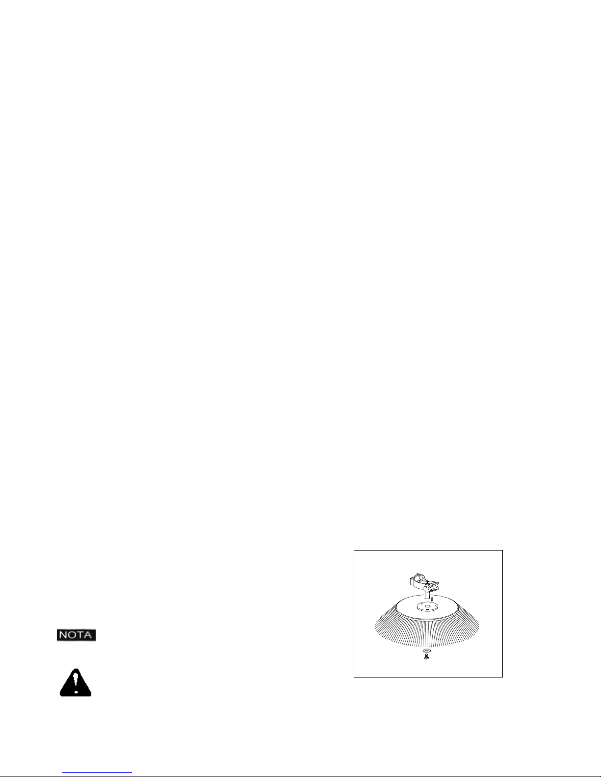
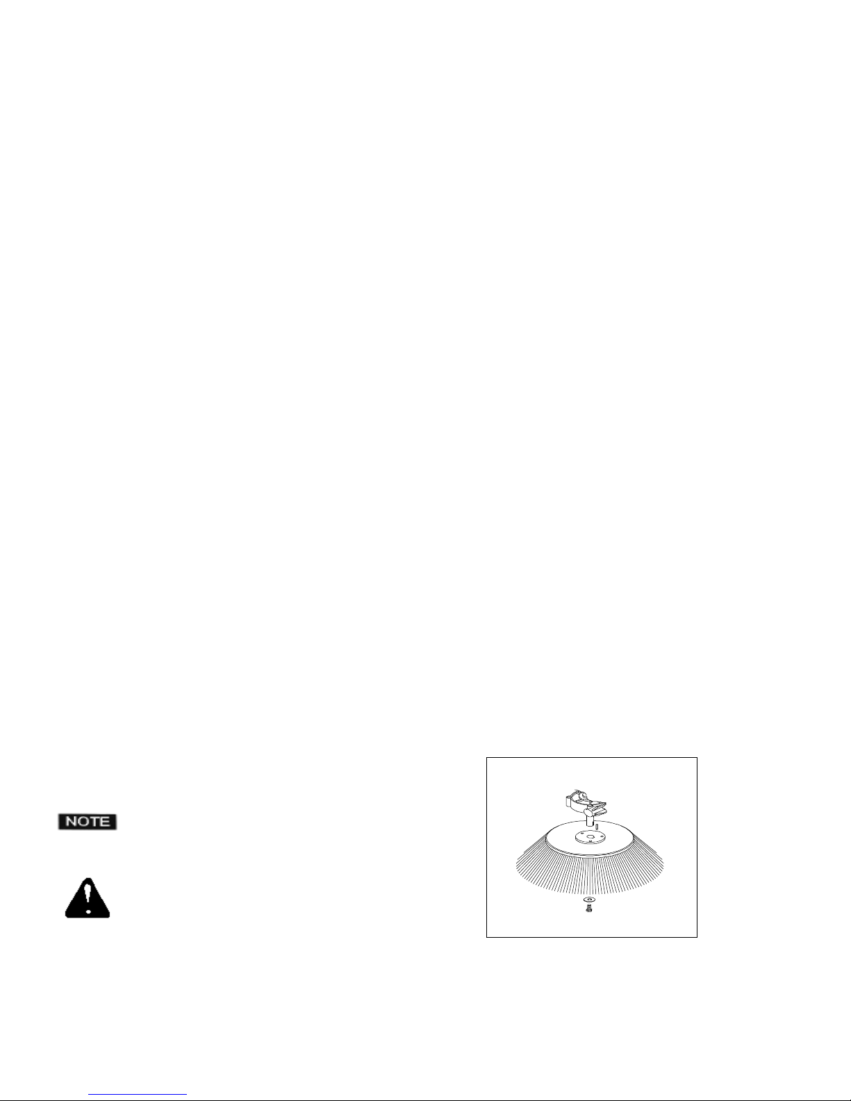
4.3 - MONTAGGIO SPAZZOLA LATERALE
Per montare la spazzola laterale nella sua corretta posizione operare
come segue:
1:Portare la leva alzaspazzola 5 / 5-A Fig.2 in posizione OFF.
2:Svitare la vite dall'albero del motore spazzola laterale.
3:Togliere la protezione dalla chiavetta.
4:Posizionare la spazzola completa di flangia sull' albero.
5:Riavvitare la vite di bloccaggio.
Per evitare di perderla durante il trasporto, la
chiave di avviamento viene sistemata all'interno
del sacchetto contenente i documenti tecnici.
Assicurarsi che il materiale d'imballo
(sacchetti,cartoni,pallet ganci ecc..) sia riposto in
una zona adeguata al di fuori dalla portata dei
bambini.
ITALIANO (Istruzioni originali)
Fig.1
Pag. 4
Page 6
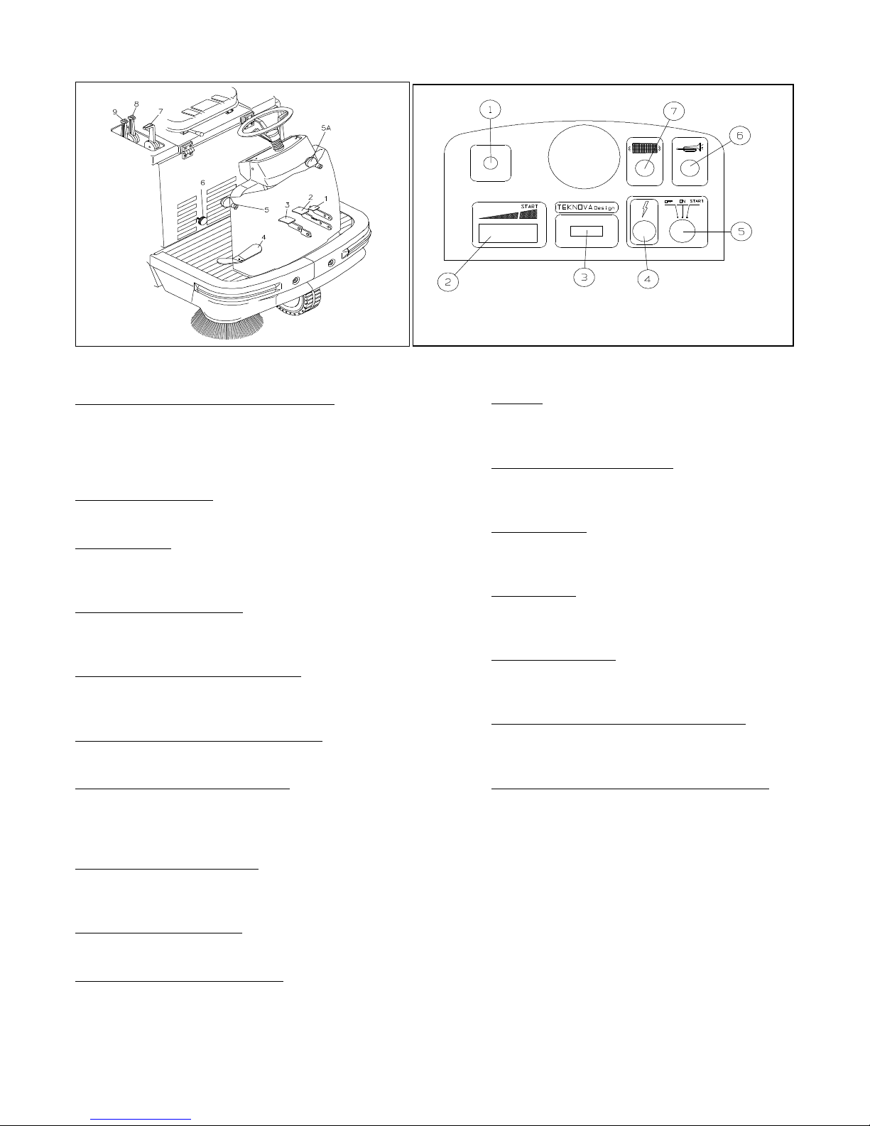
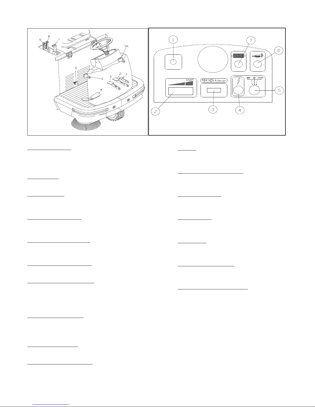
5.1 GRUPPO COMANDI
5.2 - CRUSCOTTO STRUMENTI
Fig.2
1:Pedale blocco freno ( Freno di stazionamento)
Premuto assieme al pedale freno di servizio 2 blocca quest'ultimo
inserendo cosi il freno di stazionamento.Per sbloccare il freno di
stazionamento premere il pedale del freno di servizio2 che farà
scattare il pedale di blocco freno in posizione di non lavoro.
2:Pedale freno di servizio
Azionandolo si ferma la macchina durante la fase di lavoro.
3:Pedale alza-flap
Usare qualora si debbano raccogliere particolari voluminosi ma
leggeri,si consiglia di non tenerelo premuto se non necessario.
4:Pedale di selezione direzione
Agendo su questo pedale si seleziona il senso di marcia e la relativa
velocità.
5 :Leva comando spazzola laterale Destra
Tirando ed abbassando questa leva,la spazzola si porta in posizione di lavoro.A fine lavoro,riportare la leva nella posizione precedente.
5-A :Leva comando spazzola laterale Sinistra
Come sopra per modelli con doppia spazzola laterale.
Fig.3
1:Starter
Leva di attivazione aria per accensione a motore freddo.
2:Leva di regolazione giri motore
Agendo su questa leva si regolano i giri del motore
3:Timer contaore
Indica le ore totali lavorate dalla macchina.
4:Spia tensione
Indica che la macchina è sotto tensione.
5:Chiave di accensione
Accende e spegne tutte le funzioni della macchina
6:Pulsante per l'attivazione avvisatore acustico
Premendo questo pulsante si attiva il segnalatore acustico.
6:Bypass per spostamento d'emergenza
Consente lo spostamento,in caso di necessità, della macchina a
motore spento.Svitare il pomolo di BYPASS girando di 1/2 giro in
direzione 0 MAN per poter spostare la macchina a motore spento.
7:Leva comando spazzola centrale
Portando la leva in pos. ON la spazzola centrale si porta in posizione
di lavoro. A fine lavoro,riportare la leva in posizione OFF.
8:Leva di apertura presa d'aria
Apre o chiude il flusso d'aria per l'aspirazione polveri
9:Leva disgiunzione motore (Frizione)
Disabilita tutte le funzioni collegate al motore in fase di accensione.
ITALIANO (Istruzioni originali)
7:Pulsante per l'attivazione del motovibratore filtro
Premendo questo pulsante si attiva il motovibratore per la pulizia
del filtro (Vedi Man.Filtro).
Pag. 5
Page 7
6.1 - PROCEDURA per L' AVVIAMENTO
- Sedersi sul sedile.
- Portare la leva dell'acceleratore 2 Fig.3 nella posizione di START.
- Tirare la leva dello starter 1 Fig.3
- Portare la leva di frizione 9 Fig 2 in posizione 1 -START POSITION
- e tenerla in questa posizione mentre si aziona l'interruttore a chiave
5 Fig.3.Portare l'interruttore di accensione sulla posizione di START
e tenervelo sino a che il motore non si avvia.
N.B. Non usare il motorino di avviamento per più di 5 secondi alla
volta.Se il motore non dovesse partire,lasciare andare la chiave ed attendere circa 10 secondi prima di azionare di nuovo il
motorino.Alla partenza del motore rilasciare la chiave nella posizione
ON.
Appena il motore si e messo in moto, rilasciare la leva di frizione 9
Fig.2.
Azionando il pedale di selezione marcia 4 Fig.2 la macchina inizia a
muoversi.
Premendo il pedale sul lato DESTRO la macchina si muoverà in
AVANTI.
Premendo il pedale sul lato SINISTRO la macchina si muoverà
all'INDIETRO.
ATTENZIONE:A lavoro ultimato,assicurarsi che la spazzola centrale e la spazzola laterale siano in posizione OFF e sollevate da terra,
il freno di stazionamento inserito e la chiave di avviamento disinserita.
6.3 - PULIZIA DEL CASSETTO POSTERIORE
RACCOLTA RIFIUTI.
Per svuotare il cassetto raccogli-rifiuti operare come segue:
- Sganciare la chiusura di bloccaggio del cassetto.
- Tirare il cassetto posteriore afferrandolo dalle apposite
maniglie.
- Con l'aiuto delle ruote montate sul cassetto trascinare lo stesso
fino alla zona di raccoltarifiuti.
- Rovesciare il contenuto del cassetto avendo cura di non danneg-
giare il cassetto.
- Riposizionare il cassetto nel suo vano.
- Riagganciare la chiusura posteriore.
- N.B. Considerato il peso del cassetto pieno di
polvere,è consigliabile effettuare questa operazione in due persone.
6.2 - PROCEDURA per il FUNZIONAMENTO
Dopo aver avviato la macchina seguendo le istruzioni riportate nel
paragrafo precedente, procedere come descritto secondo le proprie
esigenze, abbassare la spazzola centrale portando l'apposita leva 7
Fig2 in posizione di ON.
Abbassare,se necessario la spazzola laterale,(o le due spazzole
laterali nella versione a Doppia Spazzola) agendo sulle leve di
comando 5 - 5A Fig 2.
Nel caso in cui le spazzole dovessero sollevare della polvere durante
il lavoro,è consigliabile l'accensione dell'aspirazione per mezzo della
leva 8 Fig 2.
Se si devono raccogliere dei rifiuti voluminosi e leggeri agire sul
pedalealzaflap 3 Fig.2. Tenere premuto il pedale alzaflap solo per il
tempo necessario per effettuare questa operazione.
Per ottenere sempre il massimo dalla macchina è necessario che
questa sia sempre in perfette condizioni per garantire così anche la
massima sicurezza.
Per ottenere questo è necessario attenersi scrupolosamente a tutte
le indicazioni riportate nel paragrafo relativo alla Manutenzione
ordinaria.
Per spegnere la macchina portare la leva 2 Fig.3 in posizione di
minimo e girare la chiave 5 Fig.3 su OFF.Si consiglia di lavorare con
il motore al massimo numero di giri ( leva 2 Fig.3 ).
ATTENZIONE: Si ricorda che lo smaltimento
dei rifiuti deve essere fatto tenedo conto delle
norme vigenti
Nel caso in cui la macchina si muova anche se il pedale di selezione
della direzione non è premuto,regolare il punto morto dello spostamento come indicato dal Par.7.5.
ITALIANO (Istruzioni originali)
Pag. 6
Page 8
C O N T R O L L I C H E C K
Controllare olio impianto idraulico Check the hydraulic system's oil
x
x
Controllare l'usura delle cinghie The belts for slackening
x
Registrare il freno Adjust the brake's cable
x
Controllare il serraggio di dadi e viti The tightness of nuts and screws
x
Controllare lo stato delle spazzole The brushes for wear
x
Controllare la tenuta delle guarnizioni The gaskets for wear and leakages
x
Controllare il funzionamento di tutte le funzioni If all the functions are in working order
x
x
Ingrassare la catena dello sterzo Grase the steering chain up
x
- MANUTENZIONE ORDINARIA
TUTTE LE OPERAZIONI DI MANUTENZIONE ORDINARIA O DI MANUTENZIO STRAORDINARIA DEVONO ESSERE
EFFETTUATE DA PERSONALE COMPETENTE OPPURE DAL CENTRO DI ASSISTENZA TECNICA AUTORIZZATO. SI
RACCOMANDA DI UTILIZZARE SOLAMENTE PARTI DI RICAMBIO ORIGINALI. ATTENZIONE:NON EFFETTUARE
NESSUN TIPO DI CONTROLLO O INTERVENTO DI MANUTENZIONE DOPO UN CICLO DI LAVORO, PRIMA DI INTERVENIRE
SULLA MACCHINA ASSICURARSI CHE SI SIA RAFFREDDATA.
NON EFFETTUARE NESSUN RIFORNIMENTO O RABBOCCO PRIMA CHE LA MACCHINA NON SI SIACOMPLETAMENTE
RAFFREDDATA. PER LA MANUTENZIONE DEL MOTORE A SCOPPIO FARE RIFERIMENTO AL MANUALE SPECIFICO.
Alla consegna
On delivery
Ogni 10 ore
Every 10 hours
Ogni 50 ore
Every 50 hours
Ogni 100 ore
Every 100 hours
7.1 MANUTENZIONE BATTERIA:
La batteria deve sempre essere tenuta pulita
ed asciutta,controllare che i morsetti ed i poli siano
tenuti costantemente puliti.Periodicamente togliere
i tappi e controllare il livello dell'elettrolito rabboccando con acqua
distillata se necessario.Si ricorda che il locale dove viene effettuata
tale operazione deve essere ben areato.Non avvicinarsi con fiamme
libere e non fumare durante questa operazione.
7.2 MATERIALE DI CONSUMO
Benzina VERDE Cap. serbatoio motore: 2,5 Lt
Olio SEA 10W-30 Cap. serbatoio motore: 0,6 Lt.
Olio SEA 15W-50 Cap. impianto idraulico a livello
ITALIANO (Istruzioni originali)
serbatoio
Pag. 7
Page 9
7.3 - MANUTENZIONE DEL FILTRO
Il filtro è un componente di primaria importanza per il corretto
funzionamento della macchina.
Una sua corretta manutenzione farà si che il rendimento della
macchina sia sempre ai massimi livelli.
Il filtro può essere pulito in due modi:
1 - Tramite scuotifiltro elettrico
In dotazione alla macchina, permette con un semplice gesto di
tenere sempre il filtro in perfette condizioni.Prima di azionare
lo scuotifiltro è necessario chiudere la leva di presa aria 8 fig.2
A questo punto premere il pulsante 7 Fig 3 e tenerlo premuto per
alcuni secondi.Ripetere questa operazione 4 o 5 volte.
Si ricorda che più il filtro è tenuto pulito e migliore sarà il risultato
della pulizia.E' consigliabile effettuare questa operazione ad ogni
fine di ciclo lavorativo.
AMBIENTE POLVEROSO:Se si utilizza la
macchina in un ambiente polveroso(per esem.
carbonaie,magazzini con passaggio di automezzi
ecc..) avere l'accortezza di utilizzare lo scuotifiltro
più frequentemente.
2:-Pulizia manuale del filtro
Se il risultato della pulizia del filtro tramite scuotifiltro non risultasse efficace,e comunque ogni 20 ore di lavoro procedere alla pulizia
manuale del filtro.
Prima di effettuare qualsiasi tipo di intervento sulla macchina
assicurarsi che la stessa sia spenta e che tutte le sue funzioni
sianodisattivate,per ottenere questo stato portare l'interruttore a
chiave 5 Fig.3 in posizione OFF.
Oltre all'abituale uso dello scuotifiltro,per ottenere una pulizia più
accurata si consiglia di procedere alla pulizia del filtro come segue:
Posizionare il filtro come indicato
dall'etichetta riportata sul filtro stesso.
Filtro a pannello
Filtro a tasche
Al momento del fissaggio del filtro, assicurarsi che ci
sia perfetta tenuta tra il filtro e le guarnizioni.
ATTENZIONE Per lo smaltimento del filtro usato
attenersi scrupolosamente alle norme vigenti.
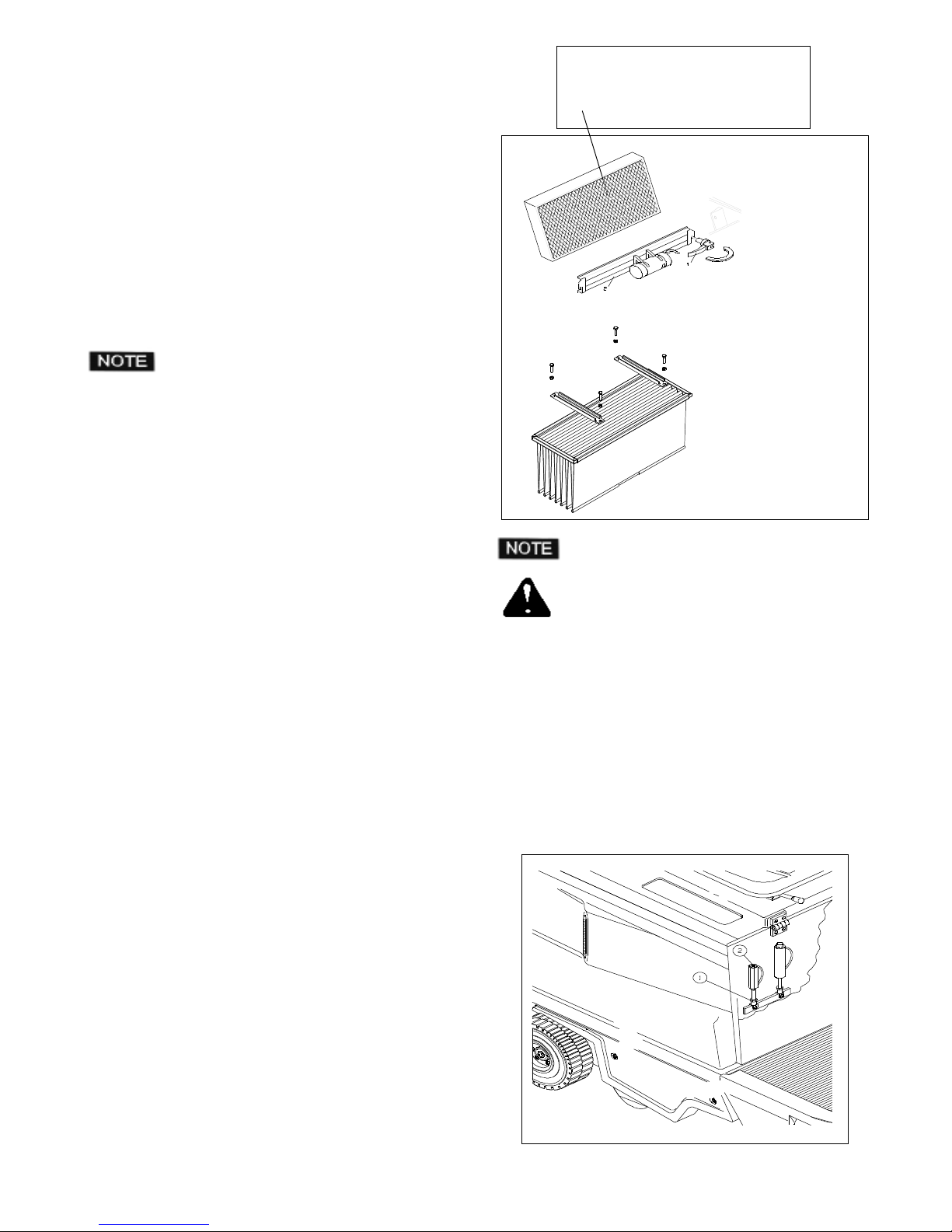
1- Sollevare il cofano porta sedile.
2- Svitare il galletto di fermo del coperchio scatola filtro.
3- Togliere il coperchio scatola filtro.
Soffiare con aria compressa il filtro in direzione del cassetto
portarifiuti,in modo che la polvere ed eventuali corpi estranei si
depositino all'interno del cassetto.
7.4 - SOSTITUZIONE DEL FILTRO
Ogni circa 200 ore di lavoro il filtro deve essere sostituito,a tal
proposito operare come segue:
1- Sollevare il cofano porta sedile.
2- Svitare il galletto di fermo del coperchio scatola filtro.
3- Togliere il coperchio scatola filtro.
4- Sbloccare la leva (1) ( filtro a pannello).
5- Togliere il telaio (2) porta motovibratore ( filtro a pannello)
6- Sfilare il filtro dal telaio porta filtro ( filtro a pannello).
Dopo aver sostituito il filtro,per il rimontaggio della
macchina,eseguire le fasi sopradescritte in senso contrario.
7- Svitare le quattro viti ( filtro a tasche).
8- Scollegare il connettore dello scuotifiltro ( filtro a tasche)
9- Togliere il filtro dalla propria sede ( filtro a tasche)
10- Pulire a fondo il filtro con un'aspirapolvere oppure sostituirlo
( filtro a tasche)
Dopo aver sostituito il filtro,per il rimontaggio della
macchina,eseguire le fasi sopradescritte in senso contrario.
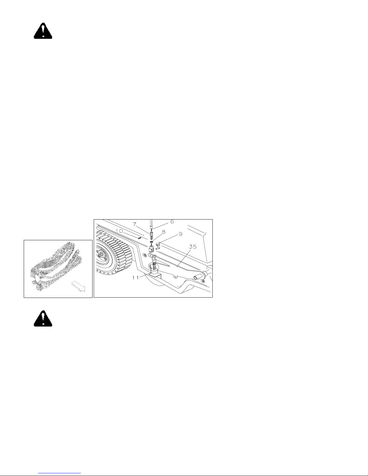
7.5 - REGOLAZIONE PUNTO MORTO
Se la macchina si dovesse muovere anche quando il pedale di
selezione 4 Fig.2 non è premuto, regolare il punto morto come
segue:
- Svitare il controdado di fermo 1 posto in prossimità della clip di
aggancio.
- Regolare tramite la vite 2 fino a che non si è trovato il punto morto
di avanzamento.
- Avvitare il controdado di fermo 1.
ITALIANO (Istruzioni originali)
Pag. 8
Page 10
7.6 SOSTITUZIONE SPAZZOLA CENTRALE
Prima di effettuare qualsiasi tipo di intervento sulla
macchina assicurarsi che la stessa sia spenta e che
tutte le sue funzioni siano disattivate. Per ottenere
questo stato portare l'interruttore a chiave 3 Fig.3 in posizione
OFF.Posizionare la leva comando spazzola centrale 6 Fig.2 in posizione OFF.
1- Svitare le viti di fissaggio carter inferiore sinistro.
2- Svitare la vite di fissaggio braccio spazzola e togliere il braccio.
3- Sfilare la molla dall'albero spazzola.
4- Svitare le 4 viti di fissaggio chiusura vano spazzola e toglierlo.
5- Sfilare la flangia e la spazzola centrale. Inserire la spazzola nuova
facendo attenzione che l'orientamento dei ranghi delle setole convoglino i detriti verso il centro della spazzola.Una volta inserita la
spazzola eseguire le oprerazioni sopra indicate in senso contrario per
rimontare la macchina.
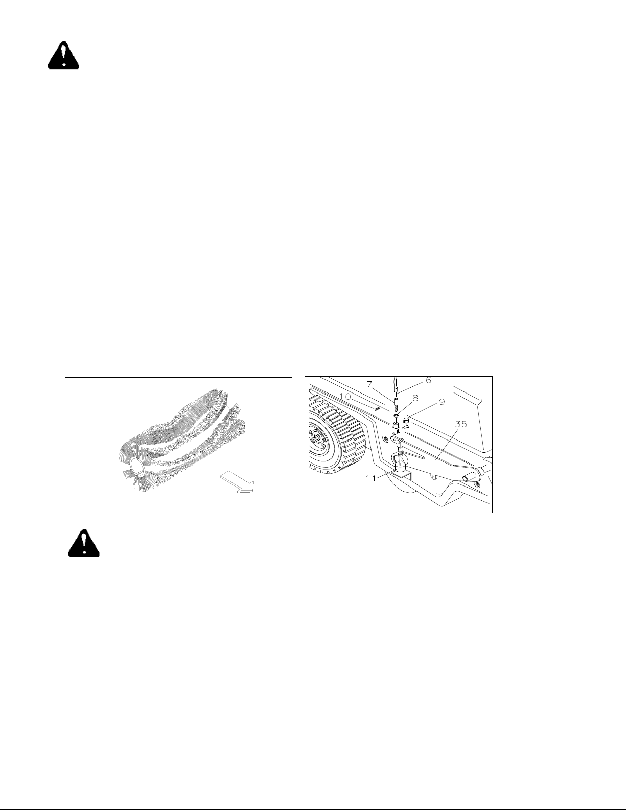
Regolazione spazzola centrale:
La spazzola centrale è un componente di importanza fondamentale
per il buon rendimento della macchina.Una sua corretta regolazione
permetterà di ottenere ottimi risultati in tempi minimi.Premesso che la
macchina viene fornita con tutte le regolazioni eseguire la regolazione
quando la spazzola e consumata. Operare come segue:Svitare i carter
inferiore e superiore Destro. Posizionare la leva 6 Fig.2 in posizione
ON.Allentare il grano 10 ed il controdado di blocco registro.Verificare
che il filo non sia in tensione e che ci sia sufficientegioco per regolare
il tampone.In caso contrario regolare il registro 7 fino ad ottenere il
gioco necessarioRegolare il tampone tramite il controdado fino a
quando tra il tampone ed il fermatampone non ci sia un gioco di circa
4 / 5 mm.Ribloccare i controdadi di blocco ed il grano ferma guaina.
7.7 Sostituzione spazzola laterale:
Posizionare la leva di comando spazzola laterale
5 (5A) Fig 2 in posizione OFF. Svitare le tre viti che
fissano la spazzola laterale alla flangia di
trascinamento.Sfilare la spazzola e sostituirla con quella nuova.
Riavvitare le tre viti di fissaggio spazzola laterale. La macchina è ora
pronta per essere riattivata.
Regolazione spazzola laterale:
La funzione della spazzola laterale è quella di portare il materiale da
raccogliere verso il centro della macchina.
La posizione ottimale per ottenere questa operazione è quella di
sfiorare il pavimento.In caso in cui si decidesse di aumentare o
diminuire la pressione della spazzola operare come segue:
- Portare la spazzola laterale in posizione di lavoro ON.
- Allentare le due viti di regolazione poste sotto il pomolo alzaspazzola.
- Regolare manualmente la spazzola nella posizione desiderata.
- Stringere le viti di regolazione.
- Riportare la spazzola laterale in posizione di non lavoro OFF.
ITALIANO (Istruzioni originali)
Pag. 9
Page 11
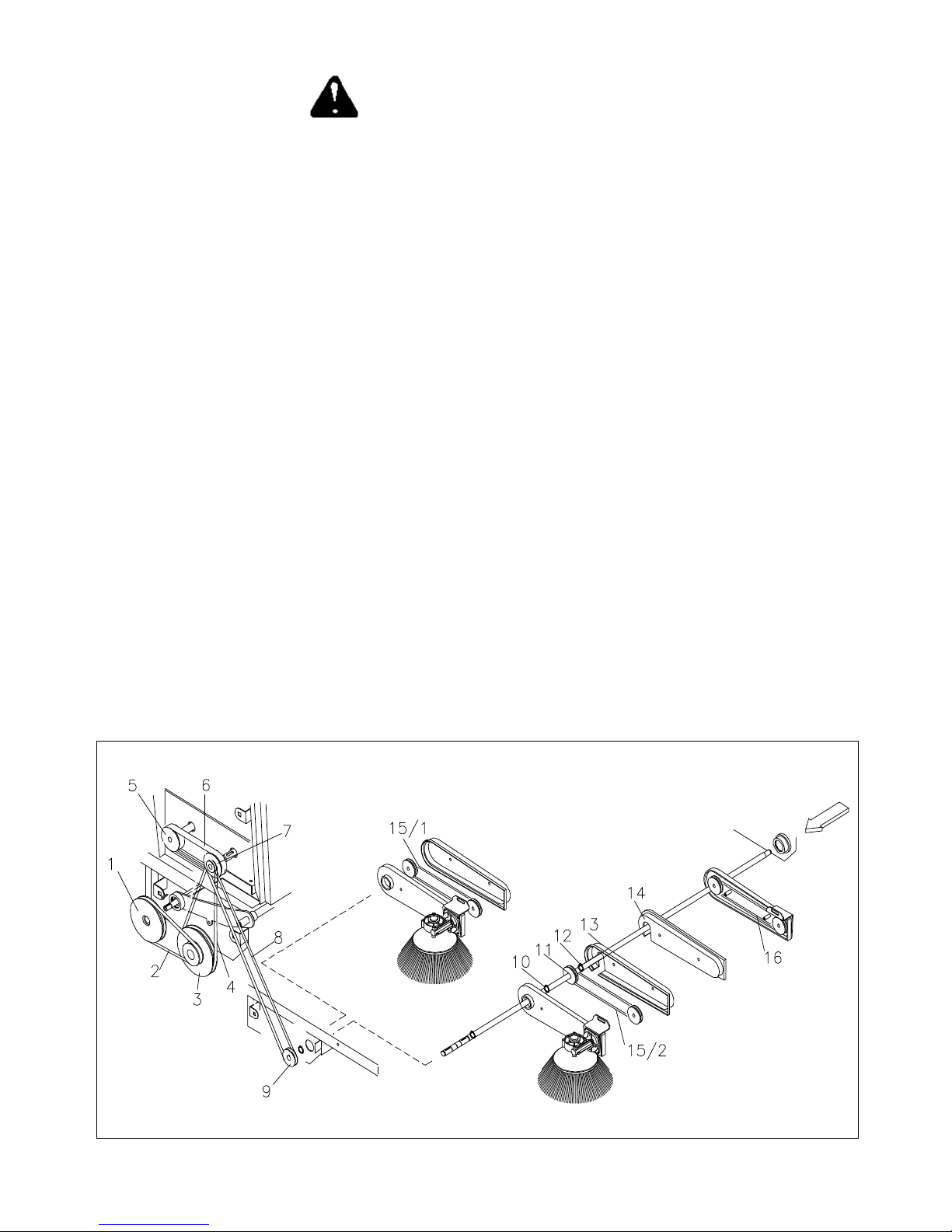
7.8 - Sostituzione cinghie
Prima di effettuare qualsiasi tipo di intervento sulla
macchina,assicurarsi che la stessa sia spenta e che
tutte le sue funzioni siano disattivate,per ottenere
questo stato portare l'interruttore a chiave 5 Fig.3 in
posizione OFF.
Dopo aver svitato le viti che fissano il carter superiore destro ed il carter
inferiore e/o eventuali carter di protezione:
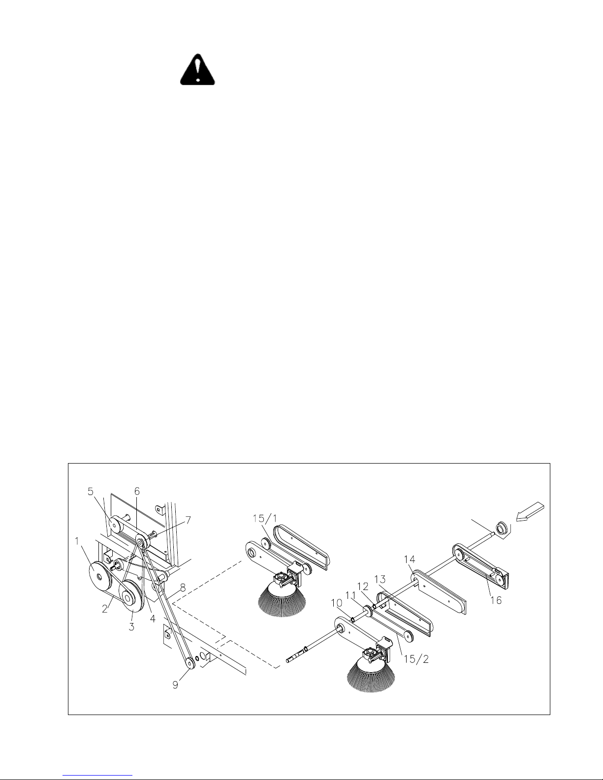
CINGHIA 2: Facendo leva con un cacciavite far uscire la cinghia
della gola di una puleggia e sostituirla.
CINGHIA 4: Facendo leva con un cacciavite far uscire la cinghia
della gola di una puleggia sostituirla.
ATTENZIONE. per togliere la cinghia 4 è necessario togliere prima la
cinghia 2.
CINGHIA 6: Svitare le due viti di bloccaggio e sfilare le 2 puleggie 5
e 7 dai rispettivi alberi.
ATTENZIONE per togliere la cinghia 6 è necessario togliere prima la
cinghia 4 e la cinghia 8.
CINGHIA 8: Facendo leva con un cacciavite far uscire la cinghia
della gola di una puleggia e sostituirla.
CINGHIA 15/1 (Vers. Singola Spazzola laterale): Facendo leva con un
cacciavite far uscire la cinghia della gola di una puleggia e sostituirla.
CINGHIA 15/2 - CINGHIA 16 (Vers. Doppia Spazzola laterale) Dopo
aver tolto i seeger di fissaggio dell'albero, e delle pulegge estrarre
l'albero fino a quando non sarà possibile togliere la cinghia.Una volta
sostituito la cinghia riposizionare l'albero e bloccarlo con i rispettivi
seeger.
ITALIANO (Istruzioni originali)
Pag. 10
Page 12
7.9 -SOSTITUZIONE DEI FLAPS
Flap laterali e posteriore fisso:svitare le viti che fissano il ferma
flap al telaio della macchina.
- Togliere il ferma flap.
- Sostituire il flap usurato con quello nuovo.
- Riposizionare il ferma flap ribloccandolo con le viti tolte in
precedenza.
Flap anteriore regolabile:sganciare la clip di fissaggio del cavo
alza flap.
- Togliere il ferma flap.
- Sostituire il flap usato con quello nuovo.
- Riposizionare il ferma flap ribloccando le viti.
- Riagganciare il cavo al flap
Prima di effettuare qualsiasi tipo di intervento sulla
macchina,assicurarsi che la stessa sia spenta e che
tutte le sue funzioni siano disattivate,per ottenere
questo stato portare l'interruttore a chiave 5 Fig.3
in posizione OFF
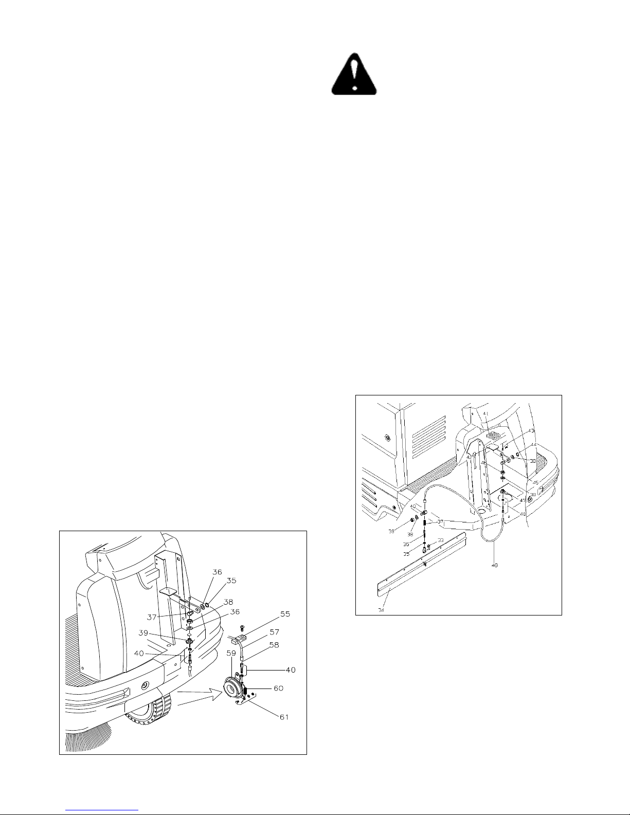
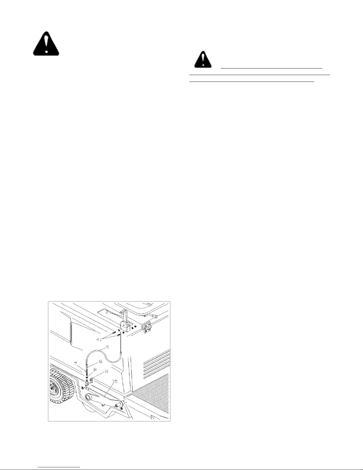
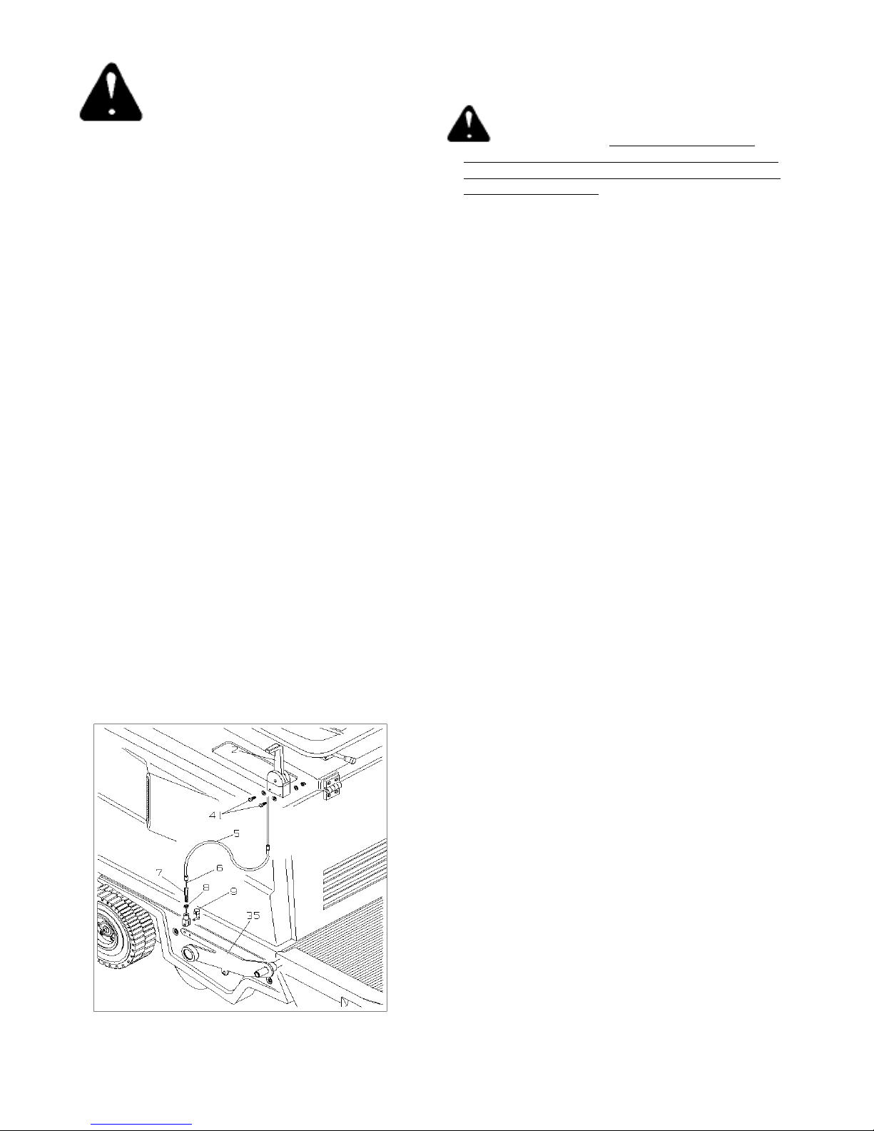
7.11 - SOSTITUZIONE E REGOLAZIONE
CAVO ALZA FLAP
Per sostituire il cavo alza flap,operare come segue:
- Svitare le viti di fissaggio musetto macchina e del paraurti e toglierli
dalla macchina.
- Svitare il morsetto ferma cavo (43) posto sul pedale.
- Sganciare la clip (33) dalla forcella del flap.
- Sfilare il cavo (36).
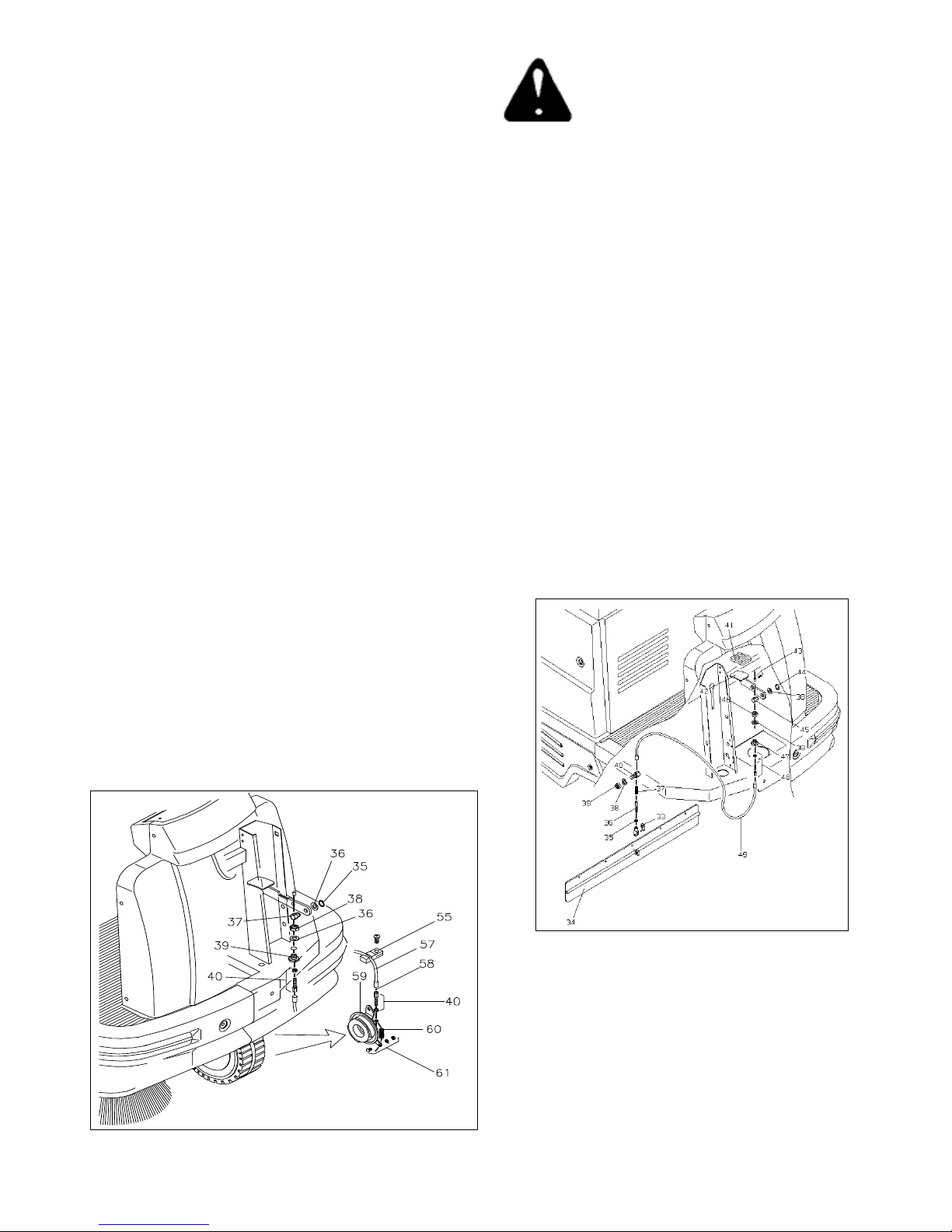
7.10 SOSTITUZIONE E REGOLAZIONE
CAVO FRENO
Per sostituire il cavo freno operare come segue:
- Svitare sia le viti di fissaggio del musetto e dei paraurti; toglierli
dalla macchina.
- Svitare il morsetto fermacavo (61) posto sul freno.
- Sfilare dal pedale il cavo facendo attenzione che durante questa
operazione la molla (60) di ritorno freno non venga persa.
Per il rimontaggio:
- Prima di procedere al rimontaggio del cavo allentare i registri (40)
ed ingrassareil cavo di acciaio.
- Dopo aver infilato il cavo nel pernofemacavo (37) posto sul pedale
del freno,far passare il cavo nel perno di registro (40).
- Infilare il cavo nella guaina (57) e di seguito la molla sul cavo.
- Bloccare il cavo con il morsetto (61).
- Bloccare la guaina completa di cavo nall'apposito morsetto ferma
guaina (55).
- Per una eventuale regolazione della frenata agire sui registri (40)
posti in prossimità della leva del freno.
Per il rimontaggio
- Dopo aver recuperato dal cavo rotto la forcella ed il dado (35) di
fermo (se ancora utilizzabili),rimontare gli stessi sul nuovo cavo
alza flap.
- Bloccare la forcella al flap tramite la clip per forcella (33).
- Inserire la molla 37 sul cavo 36. Infilare il cavo nel perno guida 40,
poi nella guaina 49 ed infine nel perno 47.
- Inserire il cavo nell'apposito morsetto ferma cavo (43) e bloccarlo.
ITALIANO (Istruzioni originali)
Pag. 11
Page 13
Prima di effettuare qualsiasi tipo di interventosulla
macchina,assicurarsi che la stessa sia spenta e che
tutte le sue funzioni siano disattivate,per ottenere
questo stato portare l'interruttore a chiave 5 Fig.3
in posizione OFF.
7.12 - SOSTITUZIONE E REGOLAZIONE DEL
CAVO ALZASPAZZOLA CENTRALE
Per sostituire il cavo alza spazzola centrale,operare
come segue:
- Portare la maniglia (2) in posizione OFF.
- Sollevare il cofano superiore.
- Svitare le viti che fissano i carter laterali superiori ed inferiori
e toglierli.
- Togliere il bullone fissaggio maniglia al supporto.
- Svitare le viti (41).
- Aprire la maniglia (2).
- Estrarre la guaina completa di filo.
- Svitare e togliere il morsetto.
- Togliere la clip (9).
- Sfilare la forcella dal bilancere.
- Sfilare il cavo (6) dalla guaina (5).
7.13 CAMBIO OLIO MOTORE
Per la periodicità del cambio dell'olio fare
riferimento al manuale del motore.
Si ricorda che questa operazione deve essere
eseguita a macchina spenta e a motore freddo. E' indispensabile far eseguire tale operazione da personale qualificato.
Dopo aver sollevato il cofano superiore della macchina ed aver
verificato che tutte le funzioni della macchina siano spente e che
il motore non è ad una temperatura tale da provocare pericoli per
il manutentore procedere come segue:
- Individuato il tubo scarico olio collegato al motore a scoppio,
farlo passare attraverso il foro situato sulla lamiera di chiusura
vano motore.
- Sfilare l'asta livello olio dal motore per favorire una più facile
fuoriuscita dell'olio.
- Posizionare una vaschetta per la raccolta dell'olio esausto in
prossimità del tubo di scarico olio e svitare il tappo di chiusura.
Per il rimontaggio
- Portare la maniglia (2) in posizione ON.
- Infilare il cavo (6) nella guaina (5).
- Agganciare la forcella al bilancere bloccandola con la clip (9).
- Inserire il morsetto nel cavo bloccandolo in modo
che con la maniglia (2) in posizione ON la lunghezza
del cavo risulti tale che il tampone di battuta tocchi il fermo di
riferimento.
- Riposizionare il morsetto nella maniglia e riavvitare le viti (41).
- Riavvitare la maniglia (2) al supporto.
- Rimontare i carter laterali.
- Ultimata l'operazione di scarico dell'olio esausto,richiudere il tubo
di scarico e riporlo all'interno del vano motore posizionandolo in
modo che non comprometta nessun movimento agli organi della
macchina.
- Riempire la macchina con dell'olio nuovo attraverso il tubo porta
asta livello olio avendo cura di misurare la quantità necessaria
( 0,7 Lt ) prima di effettuare tale operazione, questo per prevenire
eventuali danni dovuti alla fuoriuscita dell'olio.
- Terminata l'operazione di riempimento reinserire l'asta livello olio
e controllare tramite la stessa la corretta quantità di olio.
Chiudere il cofano superiore della macchina.
La macchina è pronta per essere riavviata.
SI RICORDA CHE L'OLIO ESAUSTO DEVE ESSERE SMALTITO SECONDO LE NORME VIGENTI
ITALIANO (Istruzioni originali)
Pag. 12
Page 14
Prima di effettuare qualsiasi tipo di interventosulla
macchina,assicurarsi che la stessa sia spenta e che
tutte le sue funzioni siano disattivate,per ottenere
questo stato portare l'interruttore a chiave 5 Fig.3 in posizione
OFF.
7.14 -SOSTITUZIONE MOTOVIBRATORE
SCUOTIFILTRO
Per sostituire il motovibratore scuotifiltro,procedere come segue:
1- Alzare il cofano superiore.
2- Svitare il galletto di chiusura e togliere il coperchio
scatola filtro.
3- Allentare i 4 pomelli di fissaggio filtro.
4- Sfilare il filtro dalla sua sede.
5- Svitare le 2 viti di fissaggio cavi di alimentazione e disconnettere
il motore.
6- Svitare le 4 viti di bloccaggio motore al telaio portafiltro e togliere
il motovibratore.
Per rimontare il motovibratore eseguire le operazioni sopradescritte
in senso contrario.
IMPORTANTE: RISPETTARE LA POLARITA'
NEL COLLEGARE IL MOTORE.
8.1 - ROTTAMAZIONE DELLA MACCHINA
Questo prodotto è un rifiuto speciale di tipo
RAEE, e risponde ai requisiti richiesti dalle
nuove direttive a tutela dell’ ambiente (2002/
96/CE RAEE). Deve essere smaltito
separatamente ai rifiuti comuni in ottempe
ranza alle leggi e norme vigenti.
Rifiuto Speciale. Non smaltire nei
rifiuti comuni.
NON utilizzare nessun pezzo da rottamare come ricambio.
TENERE ANCHE IN QUESTO CASO
FUORI DALLA PORTATA DEI BAMBINI
ITALIANO (Istruzioni originali)
Pag. 13
Page 15

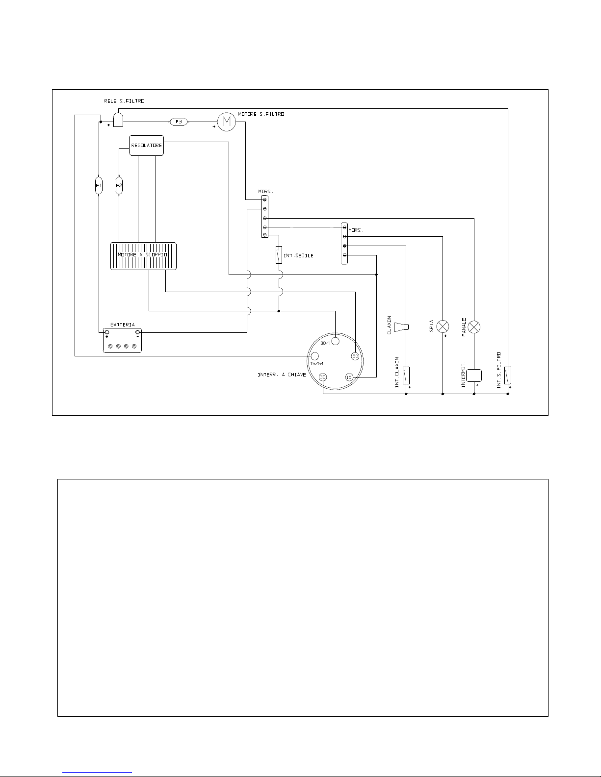
8.2 - SCHEMA ELETTRICO 8.2 - WIRING DIAGRAM
30/1: Spegnimento motore BLU
50: Accensione motore MARRONE
15: Massa - NERO
30: Uscita di linea + GRIGIO
15/54: Linea + ROSSO
Rele: 12V 20/30A
Motore scuotifiltro: 12V
Claxon: 12V
F1: 15A
F2: 15A
F3: 15A
Intermittenza: 12V
Fanale: 12V
Batteria 12V 45A
ITALIANO (Istruzioni originali)
Pag. 14
Page 16
ENGLISH (Translation of original instructions)
Pag. 1
Page 17
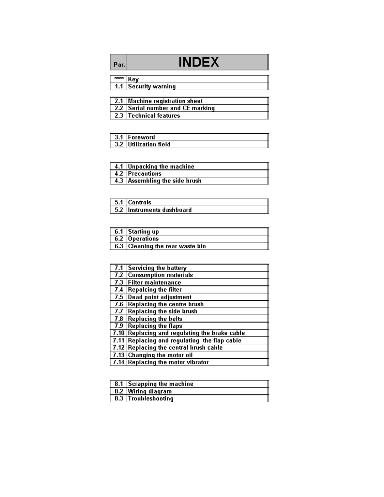
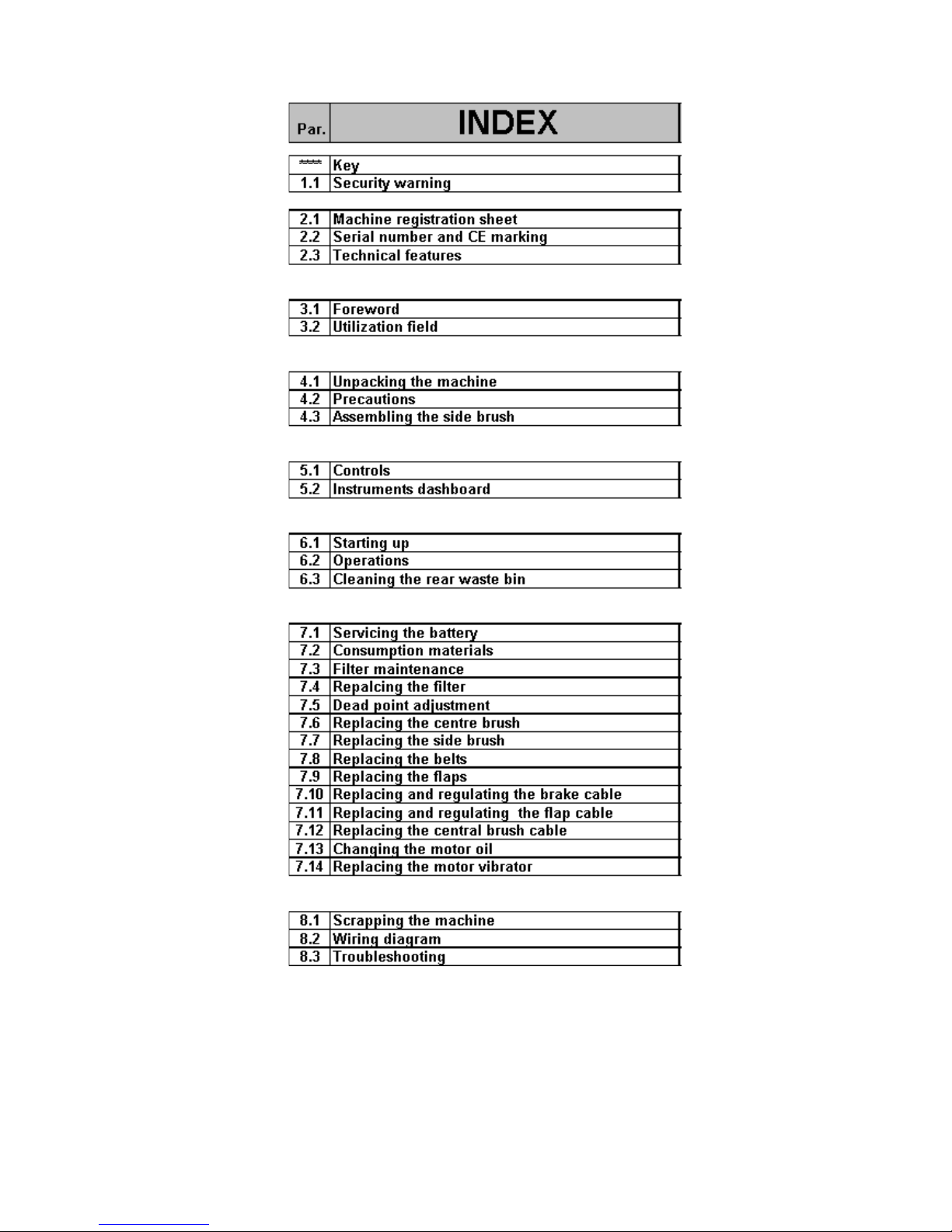
KEY
Any RIGHT or LEFT CLOCKWISE or COUNTER CLOCKWISE
indications included in this handbook are
always to be intended withrespect to the machine’s direction
of movement.
This symbol draws your attention to operations that
could cause damage to the machine if improperly
executed.
This symbol draws your attention to operations that
could cause injuries to the operator if improperly
executed.
This symbol draws your attention to operations that
must be read abaut very carefully.
Use this manual to learn the features of the machineand to understand
how to take advantage of them at theyr utmost.
1.1 SECUTITY WARNING
All the paragraph in the following chapter maycause
demange to people and/or object if improperly
executed.
ALWAYS KEEP THE MACHINE OUT OF CHILDREN.
IMPORTANT: the manufacturer CANNOT be held responsible for
damage in the event that the machine is used for purposes other
than those it was designed for use.
ATTENTION:The machine has got a presence device that allows
the starting upif the operator is in the correct working position.
The device stops the machine in the case that the operator gets up
from the seat.
Should the oil level get lower than the minimum allowed, a security
device automatically stops the machine.
Do not use a jet of water in order to wash the machine.
The machine must not be used for the sucking of toxic substances.
It is forbidden to use the machine on surfaces sloping more than
12 %.
The petrol-powered machine must be used in open and aired places
only.
The machine can only work in presence of light.
In case the machine is beining used in a place where there's a danger
for falling little objects, an helmet must be worn by the operator.
Do not use the machine to pik up cables, straps, metal wire and other
packing material.
It it forbidden to use the machine near wires, cables or similar
material.
Do not start the machine with the accelerator pressed downt could
jolt forward and cause damange to people and/or things.
The machine CANNOT and MUST NOT BE dragged.
The machine MUST NEVER be tampered with for any reason
whatsoever; in this event, the manufacturer will accept no
responsibility for improper use or damage to the machine.
The machine must be used only be qualified and authorised
personnel.
For this purpose, NEVER:
- use the machine to transport people;
- touch the moving parts of the machine;
- remove the machine’s guards when it is running.
- do not leave the operating machine unattended.
If you are working in a particularly dusty environment (for instance;
cement factories, sawmills, marble processing factories), it is
recommended to wear:
- a mask
- protective goggles
- gloves
NEVER LEAVE the machine with the key in the dashboard
unattended.
USE AND STORAGE IN ENVIRONMENTS WHERE
THERE IS A RISK OF EXPLOSION IS PROHIBITED.
ENGLISH (Translation of original instructions)
Pag. 2
Page 18
2.2 SERIAL NUMBER AND CE MARKING
Always ensure that the machine is provided with a name plate giving the serial number and CE marking in the position shown in figure.
On the contrary, advise your dealer immediately.
Serial number - CE marking
2.3 DATI TECNICI
2.3 TECHNICAL FEATURES
Tensione principale Main Power 12 V
Potenza massima totale installata Maximum installed power 5. 5 Hp
Trasmissione su 1 ruota Transmission Monoruota - One-wheel
Velocità d'avanzamento Forward gear speed 0 - 6,2 Km/h
Velocità in retromarcia Reverse gear speed 0 - 4,6 Km/h
Larghezza di pulizia con spazzola centrale Cleaning width with main brush 700 mm
Larghezza di pulizia con spazzola laterale Cleaning width with side brush 900 mm
Larghezza di pulizia con doppia spazzola laterale Cleaning width with double side brush 1100 mm
Capacità contenitore rifiuti Capacity of the waste bin 65 Lt
Filtro a pannello Panel filter 4 m²
Produttività Productivity 3800 - 5600 m²/h
Peso Weight 290 Kg
Caratteristica batteria Battery 12V / 45Ah
Motovibratore Motovibrator 12V DC 90W
Pendenza massima di utilizzo Max. sloping surface allowed 12%
Pompa a portata variabile Pump 0 - 10 cc
Motore idraulico Hydraulic motor 98 Cm³/rpm
Pressione Sonora LpA Sound Pressure LpA 76 dB
LWA MEASURED SOUND POWER LWA 90 dB
POTENZA SONORA GARANTITA LWA,g GUARANTEED SOUND POWER LWA,g 91 dB
Vibrazioni mano HAV Hand vibration HAV 2,3 [m/sec
(incertezze della misura) k (measurement uncertainty) k 1,2 [m/sec
Vibrazioni corpo HBV Body vibration HBV 0,8 [m/sec
(incertezze della misura) k (measurement uncertainty) k 0,4 [m/sec
ENGLISH (Translation of original instructions)
Pag. 3
2
]
2
]
2
]
2
]
Page 19
3.1 -FOREWORD
The purpose of this manual is to inform the operator of the basic
rules, safety rules and criteria which must be observed when using,
adjusting and maintaining themachine. The machine has been
developed and manufactured to ensure an excellent performance
andthe utmost comfort and ease of operation in a varietyof working
conditions.
Before delivery, the machine has been checked at our factory and
by our dealer to make sure it is handed over to you in perfect working
order.To maintain the machinein this condition and ensure problemfree operation, it is essential to follow the routine maintenance
instructions given in this handbook.
3.2 - UTILIZATION FIELD
4.2 - PRECAUTIONS TO BE TAKEN BEFORE ATTEMPTIN
To facilitate transport, the side brush/es have been assembled in
their actual work position.Therefore, before using the machine,
assemble them as shown in Par. 4.3.
. Fill the tank with UNLEADED petrol
. Check the engine oil level.
. Check the hydraulic system oil level.
The machine, composed of a brush and suction system,is to be
used EXCLUSIVELY to clean dry surfaces.Anyother use could be
cause of damage to people or things and is therefore PROHIBITED.
4.1 - UNPACKING THE MACHINE
- Unpack the machine with the utmost care; avoid carrying out any
operation that could damage it.Once it has been unpacked, check
whether it is damaged.If you notice that it is not in correct working
order, DO NOT use it and inform your dealer.
- For packaging and transport purposes, some parts and accessories
are supplied disconnected from the machine. To assemble them,
carefully follow the instructi-ons given in the relevant sections.
- Contents of the package
N° 1 Machine
N° 1 or 2 Side brush/es
N° 1 Ignition key
N° 1 Instruction booklet
N° 1 Spareparts’ list
N° 1 Petrol engine instruction booklet.
N° 1 Declaration of conformity
N° 1 Warranty slip
. Check that the start battery is charged
. Connect the battery respecting the polarity.
For the Gas engine serial number, refer to enclosed specific
manual.
4.3 - ASSEMBLING THE SIDE BRUSH
To assemble the side brush in its correct position, operate as follows:
1: Place the brush-rising lever 5 / 5A Fig.2 on the OFF position.
2: Unscrew the screw from the side brush motor’s shaft.
3: Take the protection away from the key.
4: Position the brush complete with flange on the shaft
5: Screw the blocking screw back.
In the case in which one of the above-mentioned parts is
missing,please inform your dealer straight away.
For security reason during the transport, the
ignition key as been fixed inside the bag
containing the technical docomentation.
Take care to keep the packaging materials
(bags, cartons, pallets, hooks, etc...) out of the
reach of children.
ENGLISH (Translation of original instructions)
Fig.1
Pag. 4
Page 20
5.1 CONTROLS
5.2 - INSTRUMENTS DASHBOARD
Fig.2 Fig.3
1:Brake locking pedal
Pressing it with the service brake, 2, disables the latter and engages
the parking brake. To release the parking brake, press service brake
2 and the brake locking pedal will snap into its rest position.
2:Service brake
Operate this pedal to stop the machine during operation.
3:Flap lifting pedal
Use the pedal when you are tackling bulky but light wastes. Do not
keep the pedal pressed down unless it is strictly necessary.
4:Direction selection pedal.
Use this pedal to select the driving direction.
5:Right side brush control lever
By pulling and pushing down the side brush lever, the brush moves
to work position and starts spinning. At the end of your work, put
the lever back to its initial position.
5-A:Left side brush control lever
As above in the double side brush version.
6:Emergency displacement bypass
Allows the machine to be moved with the engine off.Loosen the
BAYPASS knob 1/2 a round toward 0 MAN to be able to move the
machine with the engine OFF.
1:Starter
Air activating lever. For “cold engine ignition”
2:Engine rounds regulating lever
Using this lever the rounds of the motor are regulated.
3:Hourcounting timer
This indicates the total number of hours the machine has worked.
4:Tension gauge.
It indicates that the machine is live.
5:Ignition key.
Switches all the functions of the machine on and off.
6:Button to operate the horn.
Press this button to operates the horn.
7:Button to operate the filtershaker
By means of this butto the filtershaker is operated (see filter
maintenance ch.)
7:Centre brush control lever
By pushing the lever back (to ON), the centre brush moves to work
position At the end of your work, push the lever back to OFF.
8:Air intake control lever
Opens or closes the air flow for the sucking of dust.
9:Motor disjoining lever (Clutch)
It stops all the functions relating to the motor during ignition.
ENGLISH (Translation of original instructions)
Pag. 5
Page 21

6.1 - STARTING UP
- Seat on the seat
- Take the accelerator lever 2 Fig. 3 on the START position.
- Pull the starter lever 1 Fig.3.
- Bring the clutch lever 9 Fig.2 in 1-START POSITION and keep it
in this position while activating the key switch 5 Fig.3.
Take the ignition switch on the start position and keep it there until
the motor starts.
N.B. Do not use the starter for more than 5 seconds at once.Shouldn’t
the motor start, let the key go and wait for 10 sec.more or less before
using the starter again.At the starting of the engine, bring the
keyswitch on the ON position.
As soon as the engine starts, release the clutch lever9 Fig.2
Acting on the direction-selecting pedal 4 Fig.2 the machine starts
moving.
Pressing the pedal on the RIGHT side, the machine will move
FORWARD.
Pressing the pedal on the LEFT side, the machine will move
BACKWARD.
IMPORTANT: when you have finished yuor work,make sure the
centre brush and side brush are OFF and lifted from the floor,the
parking brake is engaged an the start key removed.
6.3 - Cleaning the rear waste bin.
To empty the rear waste bin operate as follows:
- Release the bin lock.
- Pull out the rear bin by grasping it by the appropriate handles.
- With the help of the wheels fitted to the bin, drag it to the waste
disposal area.
- Empty the contents taking care not to damage the bin.
- Put the bin back into the machine.
- Fasten the lock again.
- N.B. If the bin is full it will be rather heavy to handle.
Therefore it is wise to entrust this operation to two
operators.
ATTENTION: Wastes must be disposed of in accordance
to the regulations in force.
6.2 OPERATIONS
After having started the machine following the instructions of the
previous paragraph, go on as described according to one's needs,
lower the central brush bringing the proper lever 7 Fig.2 in ON
position.
Lower, if necessary the side brush (or both in the double side brush
version) acting on the control levers 5-5A Fig.2.
Should the brushes raise some dust during the work, it is advisable
to turn the sucking on by means of the lever 8 Fig.2
If some bulky and light items are to be picked up, act on the flaplifting
pedal 3 Fig.2. Keep the pedal pressed down just for the time
necessary to do this operation.
In order to have always the maximum from the machine, it is necessary
the same to be always in perfect conditions in order also to guarantee
also the maximum security.
To achieve this, it is necessary to follow carefully all the operations
described in the Maintenance paragraph.
To turn the machine OFF bring the lever 2 Fig.3 in the min. pos. and
turn the key 5 Fig.3 on OFF.It is advisable, always to work with the
highest number of rpm. (lever 2 Fig.3)
In the case the machine moves even if the direction selectionpedal
isn't pressed down, adjust the movement dead point asshown in
paragraph 7.5.
ENGLISH (Translation of original instructions)
Pag. 6
Page 22
C O N T R O L L I C H E C K
Controllare olio impianto idraulico Check the hydraulic system's oil
x
x
Controllare l'usura delle cinghie The belts for slackening
x
Registrare il freno Adjust the brake's cable
x
Controllare il serraggio di dadi e viti The tightness of nuts and screws
x
Controllare lo stato delle spazzole The brushes for wear
x
Controllare la tenuta delle guarnizioni The gaskets for wear and leakages
x
Controllare il funzionamento di tutte le funzioni If all the functions are in working order
x
x
Ingrassare la catena dello sterzo Grase the steering chain up
x
- ROUNTINE MAINTENANCE
ALL ROUNTINE MAINTENANCE AND SPECIAL MAINTENANCE MUST BE CARRIED OUT BY COMPETENT PERSONNEL OR
BY AN AUTHORISED SERVICE CENTRE.
ALWAYS USE ORIGINAL SPARE PARTS.
ALL MAINTENANCE OPERATIONS MUST BE CARRIED OUT WITH THE MACHINE OFF.
ATTENTION: DO NOT MAKE ANY KIND OF CHECK OR SERVICE JOB AFTER A WORK CICLE, BEFORE INTERVENE ON THE
MACHINE MAKE SURE THAT IT HAS COOLED DOWN. DO NOT MAKE ANY REFILL OR REFUEL BEFORE THE MACHINE HAS
COMPLETELY COOLED DOWN. FOR WHAT THE SERVICING OF THE GAS ENGINE, REFER TO THE SPECIFIC MANUAL.
Alla consegna
On delivery
Ogni 10 ore
Every 10 hours
Ogni 50 ore
Every 50 hours
Ogni 100 ore
Every 100 hours
7.1 SERVICING THE BATTERY:
The battery must be kept clean and dry. Keep the
terminals and polesclean.Periodically,remove the
caps and check the electrolyte level.If necessary top up
with distilled water.The battery should be serviced in a properly
ventilated area. During this operation,do not expose the battery to
naked flames and do not smoke.
7.2 CONSUMPTION MATERIALS
ENGLISH (Translation of original instructions)
UNLEADED Petrol Tank capacity : 2.5 Lt.
SEA 10W-30 Oil Tank capacity : 0.6 Lt.
SEA 15W-50 Oil Full hydraulic system tank.
Pag. 7
Page 23
7.3 - FILTER MAINTENANCE
The filter is a component of primary importance for the correct work
of the machine.Its correct maintenance will keep the functioning of
the machine always to the highest levels.
The filter can be cleaned in two ways:
1 - The electric filter shaker
This instrument is simple to use and allows you to keep the filter
in perfect working order. To operate the shaker, push down the
switch (7, fig. 3) and hold it down for a few seconds. Repeat the
operation 4 or 5 times.Remember that the cleaner the filter, the
better the results.This operation should be carried out after every
work cycle.
DUSTY ENVIRONMENT:If you are using the
machine in a particularly dusty environment ( i.e.
warehouses with trucks passing, sawmills,
ecc..remember that the filtershaker should be used
more frequently.
2. Cleaning the filter manually
In the case in which the cleaning of the filter by the filter-shaker
wouldn't be effective,and every 20 working hours anyway,proceed
with the manual cleaning of the filter.
Before carrying out every operation on the machine,make sure that
this last be switched off and that all of its functions be disactivated,to
get to this state, set the key switch 5 Fig.3 in the OFF position.
In order to attain to a more thorourg cleaning it is advised to proceed
a follows in addition to the use of the filter-shaker:
Place the filter as indicated on the label
stuck on the same filter.
Panel filter
Pocket filter
When fastening the filter,make sure that filter and
gaskets are tightproof.
WARNING:To get rid of the filter, follow strictly the
directing laws.
1 - Lift the bonnet where the seat is located.
2 - Slacken the wing nut on the filter box cover.
3 - Remove the cover.
Clean the filter blowing with a jet of compressed air directed
towards the waste bin, so that any residual falls into the bin.
7.4 - REPLACING THE FILTER
Every 200 hours of work, the filter must be replaced. To do so:
1 - Lift the bonnet where the seat is located.
2 - Slacken the wing nut on the filter box cover.
3 - Remove the cover.
4- Loosen the 4 locking rings
5- Loosen the 4 knobs
6 - Remove the filter from the filter holder.
After replacing the filter, carry out the above operations
in reverse order.
7- Unscrew the four screws (Pocket filter).
8 - Disconnect the connector on the filter shaker (Pocket filter).
9 - Remove the filter from its housing (Pocket filter).
10 - Thoroughly clean the filter with a vacuum cleaner or replace it
(Pocket filter).
After replacing the filter, carry out the above operations
in reverse order.
7.5 - DEAD POINT ADJUSTMENT
Should the machine move also when the selection pedal4 Fig.2 is
not pressed, adjust the dead point as follows:
- Unscrew the counternut 1 placed nearthe coupling clip.
- Adjust by means of the screw 2 until you don’t find the advancing
point.
- Screw the blocking counternut 1 up.
ENGLISH (Translation of original instructions)
Pag. 8
Page 24
7.6 ADJUSTING THE CENTRE BRUSH
Before carrying out any work on the machine, make
sure it is off and all its functions disabled. To do so,
turn the key switch 3, fig. 3 OFF.
Push the centre brush control lever 6, fig. 2 to OFF.
1 -Loosen the screws fixing the bottom left casing.
2 -Loosen the screw fixing the brush locking arm.
3 -Remove the spring from the brush shaft.
4 -Remove the 4 screws closing the brush compartment.
5 -Remove the flange and the centre brush.
Insert the new brush and make sure that its rows of brushes
direct the wastes towards its centre.
Once the brush has been inserted, carry out the operations in
reverse order to reassemble the machine.
Adjusting the centre brush
The main brush is an essential part of the machine.Correct
regulation will help you achieve better results in less time.
The machine is delivered regulated; however should you
require further regulations:
Unscrew the bottom right casing;push the lever 6, fig. 2 to its
ON position.Loosen the nut 10 and the register-blocking
counter nut. Verify that the wire isn't in tension and that there
is gap enough for the pad to be adjusted. If not, adjust the
register 7 until you don't have the gap needed.Adjust the pad
by means of the counter nut until when between the pad and
the padblocker there is a gap 4 / 5 mm roughly.
Re-block the blocking counter-nuts and the sheathing blocking
dowel.
7.7 Replacing the side brush:
Push the side brush control lever 5 (5A) Fig.2 to
OFF.Loosen the three screws that secure the
side brush to the drive flange.Remove the brush
and replace it with a new one.Tighten the three side brush
fixing screws.The machine is now ready to be turned on.
Adjusting the side brush
The side brush directs the material towards the centre ofthe
machine so that it can be drawn into the bin.
It should be high enough to brush lightly against the floor.
Should you decide to increase or decrease the pressure of the
brush on the floor:
- move the brush to its work position (ON).
-Loosen the two adjustment screws under the brush lifting
knob.
-Manually adjust the brush.
-Tighten the adjustment screws.
-Move the side brush back to rest position (OFF).
ENGLISH (Translation of original instructions)
Pag. 9
Page 25
7.8 - Replacing the belts
Before carrying out any work on the machine,make
sure that it is off and that all its functions aredisabled.
This is done by turning the key switch (5, fig. 3)
OFF.
After loosening the screws that keep the top right casing and
bottom right casing in place:
BELT 2: Using a screwdriver as a fulcrum, get the belt out of
the pulley race and change it.
BELT 4: Using a screwdriver as a fulcrum, get the belt out of
the pulley race and change it.
ATTENTION: In order to take the belt 4 it is necessary to take the
belt 2 out first.
BELT 6: Unscrew the 2 blocking screw and slip pulley 5 and 6
fom the proper shafts.
ATTENTION: In order to take the belt 6 it is necessary to take the
belt 4 and 8 out first.
BELT 8: Using a screw driver as a fulcrum, get the belt out of the
pulley race and change it.
BELT 15/1: ( Single side brush version) Using a screw driver as a
fulcrum, get the belt out of the pulley race and change it.
BELT 15/2 - BELT 16: ( Double side brush version)
After removing the snap rings which secure the shaft and pulleys
in place, pull the shaft outwards until it is no longer possible remove
the belt. After replacing the belt, put shaft back and fix it using the
appropriate snap rings.
ENGLISH (Translation of original instructions)
Pag. 10
Page 26
7.9 - REPLACING THE FLAPS
Fixed side and rear flaps: loosen the screws that secure the flap
retainer to the machine’s chassis.
- Remove the flap retainer.
- Replace the flap with a new one.
- Put the flap retainer back in place and fasten the screws you
previously removed.
Before carrying out any work on the machine,
make sure that it is off and that all its functions are
disabled. This is done by turning the key switch
5, fig. 3 OFF.
7.11 - REPLACING AND REGULATING
THE FLAP LIFTING CABLE
Adjustable front flap: release the clip fastening the flap lifting cable.
- Remove the flap retainer.
- Replace the flap with a new one.
- Put the flap retainer back in place and fasten the screws you
previously removed.
- Fasten the flap lifting cable to the flap.
7.10 REPLACING AND REGULATING
THE BRAKE CABLE
To replace the brake cable:
-Loosen the machine nose fixing screws and remove the nose.
-Loosen the bumper fixing screws and remove the bumper.
-Loosen the cable clamp (61) fitted to the brake.-Pull the cable
out of the pedal, making sure not to loose the brake return spring
(60).
Re-assembling:
-Before fitting the cable, loosen the adjustment screws (40).
-After slotting the cable through the cable holder pin (37) located
on the brake pedal, first slot the cable through the centring pin (39),
then through the adjustment screw (40).
-Fit the cable into the sheath (57) and the spring onto the cable.
-Secure the cable in place with the clamp (61).
-Clamp the sheath and cable into the appropriate sheath holding
clamp (55).
-To adjust the braking efficiency, act on the adjustment screws (40)
located near the brake lever.
To replace the flap lifting cable:
-Loosen the machine nose fixing screws and remove the nose.
-Loosen the bumper fixing screws and remove the bumper.
-Loosen the cable clamp (43) fitted to the brake.
-Remove the clip (33) from the flap fork.
-Remove the cable (36).
Reassembling:
-After removing the fork and nut (35) from the broken cable (if they
are in good repair), mount
them on the new flap lifting cable.
-Secure the fork to the flap using the clip (33). Put the spring (37)
onto the cable and slot the cable through the guide pin (40). Insert
the cable (36) into the sheath (49) and then slot it through the
centring pin (47). Insert the cable into the cable clamp (45) and
secure it in place with the other clamp (43).
ENGLISH (Translation of original instructions)
Pag. 11
Page 27
Before carrying out any work on the machine,make
sure that it is off and that all its functions aredisabled.
This is done by turning the key switch 5, fig.3 OFF.
7.12 - REPLACING AND REGULATING
THE CENTRE BRUSH LIFTING CABLE
To replace the centre brush lifting cable:
-Turn the handle (2) to OFF.
-Lift the top bonnet.
-Loosen the screws fastening the top and bottom side casings.
-Remove the top and bottom side casings.
-Remove the bolt fastening the handle to the handle support.
-Loosen the screws (41).
-Open up the handle (2).
-Remove the sheath and wire.
-Unscrew and remove the clamp.
-Remove the clip (9).
-Remove the fork from the rocker.
-Remove the cable (6) from the sheath (5).
7.13 CHANGING THE MOTOR OIL
For the periodicity of oil changing refer to the
engine's handbook. You are reminded that this
operation must be carried out whit the machine off and the
engine cool. It is necessary for this operation to be carried
out by trained personnel.
Raise the top bonnet of the machine and make sure all machine
functions are disabled. Also ensure that the temperature of the
engine is sufficiently low to prevent the servicing technician from
getting scorched. This being done, proceed a follows:
- Locate the oil drainage pipe connected to the engine and slot it
through the opening on the engine compartement cover plate.
. Remove the oil level dipstick from the engine to facilitate oil
drainage.
. Put a container for exhaust oil under the drainage pipe and
aunscrew the cap
Reassembling:
-Turn the handle (2) to ON.
-Slot the cable (6) into the sheath (5).
-Hook the fork to the rocker and lock it in place with the clip (9).
-Fit the clamp to the cable and fix it so that when the handle (2) is
in ON position the striker cap touches the reference stop.
-Fit the clamp into the handle and tighten the screws(41).
-Secure the handle (2) to its fastening element.
-Reassemble the machine’s casings.
. After the oil has been drained, shut off the drainage pipe and put
it back into the engine compartment . Its position should not
interfere whith the moving parts of the machine
. Fill the machine with oil by pouring it trought the pipe which
holds the dipstick. Make sure to measure the right quantity ( 0,7
Lt ) before you carry out this operation, in order to prevent any
damange arising out of oil leakages.
. After filling, put the dipstik back into its pipe and use it to check
whether the amount of oil is sufficient.
Close the top bonnet of the machine.
The machine is ready to be started
DISPOSE OF EXAUST OIL IN ACCORDANCE TO THE LAWS
IN FORCE.
ENGLISH (Translation of original instructions)
Pag. 12
Page 28
Before carrying out any work on the machine,make
sure that it is off and that all its functions aredisabled.
This is done by turning the key switch (5, fig.3)OFF.
7.14 - REPLACING THE FILTER SHAKER
MOTOR VIBRATOR
To replace the filter shaker motor vibrator, proceed as follows:
1 -Lift the top bonnet.
2 -Loosen the wing nut and remove the filter box cover.
3 -Loosen the 4 filter fixing knobs.
5 -Remove the filter from its seat.
6 -Loosen the 2 power supply cable fixing screws and disconnect
the motor.
4 -Remove the 4 motor fixing screws from the filter holder and
remove the motor vibrator.
To reassemble the motor vibrator carry out these operations in
reverse order.
IMPORTANT: WHEN CONNECTING THE MOTOR,
RESPECT ITS POLARITY.
8.1 - SCRAPPING THE MACHINE
This product is classified as RAEE type special waste and
is covered by the requisites of the new environmental
protection regulations (2002/96/CE RAEE). It must be
disposed of separately from ordinary waste in compliance
with current legislation and standards.
Special waste. Do not dispose of with
ordinary waste.
DO NOT use scrap pieces as spareparts
ALSO IN THIS CASE KEEP OUT OF
THE REACH OF CHILDREN
ENGLISH (Translation of original instructions)
Pag. 13
Page 29
8.2 - SCHEMA ELETTRICO 8.2 - WIRING DIAGRAM
30/1: Engine extinction BLUE
50: Engine Ignition BROWN
15: Mass - BLACK
30: Line out + GREY
15/54 Line + RED
Relais: 12V 20/30A
Filtershhaker’s Motor: 12V
Horn: 12V
F1: 15A
F2: 15A
F3: 15A
Intermittence: 12V
Light: 12V
Battery: 12V 45 Ah
ENGLISH (Translation of original instructions)
Pag. 14
Page 30
FRANÇAIS (Traduction du mode d’emploi original)
Pag. 1
Page 31

CONVENTIONS ET LEGENDE
Les éventuelles indications DROITE ou GAUCHE, DANS
LE SENSE DES AGUILLES D'UNE MONTRE, CONTRE LE
SENSE DE CELUI D'UNE MONTRE, citées dans ce livret se réfèrent
toujours au sens de marche avant de la machine.
Les paragraphes précédés de ce symbole traitent des sujets
qui doivent être respectés, sous peine de causer des dégâts
à la machine.
Les paragraphes précédés de ce symbole traitent des sujets
qui doivent être respectés sous peine de provoquer des
lésions.
Les paragraphes précédés de ce symbole traitent des sujets
qui doivent être lus très soigneusement.
Utilisez ce manuel pour apprendre les caractéristiques de la machine
et pour comprendre comment les exploiter au mieux.
1.1-CONSEILS POUR LA SECURITÉ
Tous les paragraphes traités dans le chapitre suivant des
sujets qui doivent être respectés, sous peine de causer des
dégâts à la machine et/ou aux personnes.
GARDEZ LA MACHINE AU DEHORS DE LA
PORTÉE DES ENFANTS.
ATTENTION: La machine est douée d'un dispositif de presence qui
permets à la m ême de se mouvoir seulement si l'operateur se trouve
dans la correcte position de travail. Ce dispositif va arrêter la
machine dans le cas que l'operateur se léve de son siége.
Si le niveau de l'huile est inférieur à la limite minimum acceptée, un
dispositif de sécurité arrête automatiquement le moteur.
Jamais laver la machine avec un jet d'eau.
La machine ne doit pas être utilisée pour l'aspiration de subtances
toxiques.
C'est enterdit d'utiliser la machine sur surfaces avec une pente
superieure à 12%.
La machine peut travailler seulement dans des lieux illuminés.
Utiliser la machine exclusivement dans des milieux ouverts et arérés.
Dans le cas òu la machine soit utilisée dans un lieu òu il y a le risque
de chute de petites objets, l'operateur doit porter un casque de
protection.
IMPORTANT Le constructeur NE PEUT PAS être responsable des
dégâts provoqués par la machine si celle-ci n’est pas utilisée
conformément à l’usage auquel elle est destinée
La machine NE PEUT et NE DOIT pas être traînée.
La machine NE DOIT PAS subir aucune manipulation. Le cas échéant,
le constructeur déclinera toute responsabilité quant au bon
fonctionnement et aux éventuels dégâts provoqués par la machine.
La machine doit être utilisée exclusivement par des personnes
expertes et autorisées. Nous rappelons à ce propos qu’il est
ABSOLUMENT INTERDIT de :
- Transporter des personnes. Conduisant excludé
- Toucher aux parties en mouvement de la machine
- Enlever les carters quand la machine est en marche.
- Abandoner la machine allumée.
Vous vous devez habiller d’une manière adéquate au type de travail
que vous faites.
Si vous opérez dans un endroit très poussiéreux, par ex. cimenterie,
scierie, chantiers nous conseillons de porter :
- une masque
- des lunettes de sécurité
- des gants
Ne pas utiliser la machine pour ramasser des fils, feuillards, fils de fer
ou autres objets du même genre.
Il est enterdit d'utiliser la machine à proximité de câbles, fils ou autres
objets similaires.
Ne pas faire demarrér la machine avec le pedal del'accelerateur appuyé,
sa départ soudaine pourrait provoquer des dégats à choses et/òu
personnes.
UTILISATION ET STOCKAGE INTERDITS DANS LES
MILIEUX A ATMOSPHERE POTENTIELLEMENT
EXPLOSIVE
N'ABANDONNEZ jamais la machine avec la clé inserée dans le
tableau de bord.
FRANÇAIS (Traduction du mode d’emploi original)
Pag. 2
Page 32

2.2 NUMÉRO DE SERIE et MARQUE CE
Vérifiez si la machine porte la plaque avec numéro de série et
marque CE positionnée comme montré dans la figure.Sinon,
numéro de série
2.3 DATI TECNICI 2.3 DONNÉES TECHNIQUES
Tensione principale Tension principale 12 V
Potenza massima totale installata Puissance max. totale instalée 5. 5 Hp
Trasmissione su 1 ruota Transmission sur le 1 roues arrière Monoruota Einradig
Velocità d'avanzamento Vitesse d'avance 0 - 6,2 Km/h
Velocità in retromarcia Vitesse de marche arriére 0 - 4,6 Km/h
Larghezza di pulizia con spazzola centrale Largeur de nettoyage "brosse centrale" 700 mm
Larghezza di pulizia con spazzola laterale Largeur de nettoyage "brosse latérale" 900 mm
Larghezza di pulizia con doppia spazzola laterale Largeur de travail avec double brosse latérale 1100 mm
Capacità contenitore rifiuti Capacité de la poubelle 65 Lt
Filtro a pannello Filtre à panneau 4 m²
Produttività Productivité "V d'avance 4-6 Km/h" 3800 - 5600 m²/h
Peso Poids 290 Kg
Caratteristica batteria Données batterie 12V / 45Ah
Motovibratore Motovibreur 12V DC 90W
Pendenza massima di utilizzo Pente max. d'utilisation. 12%
Pompa a portata variabile Pompe à portée variable 0 - 10 cc
Motore idraulico Moteur Hydraulique 98 Cm³/rpm
Pressione Sonora LpA Pression Sonore LpA 76 dB
POTENZA SONORA MISURATA LWA PUISSANCE ACOUSTIQUE MESUREE LWA 90 dB
POTENZA SONORA GARANTITA LWA,g PUISSANCE ACOUSTIQUE GARANTIE LWA,g 91 dB
Vibrazioni mano HAV Vibrations mains HAV 2,3 [m/sec
(incertezze della misura) k (incertitude de mesure) k 1,2 [m/sec
Vibrazioni corpo HBV Vibrations corps entier HBV 0,8 [m/sec
(incertezze della misura) k (incertitude de mesure) k 0,4 [m/sec
FRANÇAIS (Traduction du mode d’emploi original)
Pag. 3
2
]
2
]
2
]
2
]
Page 33

3.1 - INTRODUCTION
Le but de ce livret d’instructions est de servir de guide. Il contient
des renseignements pratiques sur la sécurité, le fonctionnement, le
réglage et l’entretien de la machine.
La machine a été conçue et réalisée pour assurer le maximum de
prestations, de confort et de facilité de travail en toutes conditions.
La machine a d’abord été contrôlée à l’usine puis par notre concessionnaire en vue de vous assurer des conditions parfaites lors de la
livraison.
Pour conserver la machine dans ces conditions óu assurer un travail
sans problèmes, il est indispensable de respecter les opérations
d’entretien ordinaire décrites dans ce livret.
4.2 Précautions à prendre avant de mettre la
machine en marche.
Afin de faciliter le transport, la brosse latérale / s , ne sont pas
montés dans leurs positions de travail. Procédez au montage
suivant la description reportée dans le livret.
. Remplir le résérvoir avec de l'essence VERTE sans plomb.
. Contrôler le niveau de l' huile du moteur.
Contrôler le niveau de l' huile de l'installation hydraulique
3.2 - UTILISATION DU PRODUIT
La machine est destinée EXCLUSIVEMENT au nettoyage, par brossage et aspiration, de surfaces sèches.Toute autre utilisation peut
provoquer des dégâts matériels et des blessures et est par conséquent
ABSOLUMENT INTERDITE.
4.1 - DEBALLAGE
Déballez la machine très soigneusement et évitez les manoeuvres qui
pourraient la détériorer. Une fois qu’elle est déballée, vérifiez s’il ne
manque rien.S’il manque quoi que ce soit n’utilisez PAS la machine et
adressez-vous à votre revendeur.
Pour des raisons d’emballage et de transport, certains détails et certains
accessoires à option sont fournis en pièces détachées. Pour un
montage correct suivez les instructions reportées aux paragraphes
spécifiques de ce livret.
L’emballage contient :
N° 1 Machine.
N° 1 o 2 Brosse latérale.
N° 1 Clés de démarrage
N° 1 Livret instructions
N° 1 Livret pièces de rechange
N° 1 Livret instructions moteur termique
N° 1 Declaration de conformitè
N° 1 Coupon garantie
. Contrôler que la batterie de start soit chargé.
. Connexer la batterie en respectand la pôlarité.
Pour les données du moteur à explosion, consultez
le manuel spécificique.
4.3 - MONTAGE BROSSE LATÉRALE
Pour monter la brosse latérale dans sa position correcte agir de la
façon suivante:
1 : Mettez le levier lève-brosse 5 Fig.2 sur OFF.
2 : Dévissez la vis de l’arbre moteur brosse latérale.
3 : Quittez la protection de la clé
4 : Positionnez la brosse avec sa bride sur l’arbre.
5 : Serrez la vis de bloquage.
S’il vous manque une des pièces citées ci-dessus, adressez-vous
immédiatement au revendeur.
Á fin de ne pas la perdre pendant le transport, la clé
de mise en marche est placée dans le sachet qui
contient les documents téchniques.
Vérifiez si les emballages (sachets, cartons, palettes,
crochets, etc.) sont rangés dans une zone adéquate
hors de la portee des enfants.
FRANÇAIS (Traduction du mode d’emploi original)
Fig.1
Pag. 4
Page 34

5.1 - GROUPE DES COMMANDES
5.2 - TABLEAU DE BORD
Fig.2
1: Pédale de frein de stationnement
Cette pédale sert à actionner le frein de la machine en stationnement.
Appuyez sur la pédale de frein 2 et sur la pédale de blocage en même
temps. Pour ôter le frein de stationnement, appuyez uniquement sur
la pédale 2: la pédale se relâchera automatiquement.
2: Pédale de frein
Pour freiner.
3: Pédale de la bande
Quand vous devez relever la bande de protection, appuyez sur cette
pédale qui commande le mouvement haut/bas de la bande. Utilisezla uniquement si nécessaire.
4: Pedal de sélection direction
En agissant sur ce pedal on peut selectioner le sens de la marche
et rélative vitesse.
5: Levier de commande de la brosse latérale droite
En tirant et en abaissant le levier brosse latérale, la brosse se met en
position de travail et commence à tourner.Pour arrêter la brosse
latérale, une fois le travail terminé, ramenez le levier dans sa position
initiale.
5-A: Levier de commande de la brosse latérale Gauche.
Comme ci-dessus pour les modeaux avec double brosse latérale.
6: Bypass pour déplacement d’emergence.
Ça permets le déplacement, en cas de necessité de la machine
avec le moteur arrêté.
Fig.3
1: Starter
Levier d’activation de l’air pour démarrage avec moteur froid.
2: Levier de regulation des tours du moteur
En agissand sur ce levier, on peut réguler les tours du moteur.
3: Timer compte-heures.
Indiques les heures totales dont la machine a été utilisée.
4: Indicateur de tension.
Indiques que la machine est sous-tension.
5: Cléf de contact.
Allumes et éteint toutes les fonctions de la machine.
6: Bouton pour l’activation de l’avertisseur acoustique.
En poussand ce bouton on activera l’avertisseur acoustique.
7:Bouton pour l’activation du secoueur du filtre.
En poussand ce bouton on activera le secoueur du filtre. (v.
Entretien)
7: Levier commande brosse centrale.
En portand le levier sur la position de ON, la brosse centrale est
mise en position de travail.
À la fin du travail, remettre le levier en position de OFF.
8: Levier de ouverture de la prise d’air.
Ouvres òu fermes le flux d’air pour l’aspiration.
9: Levier de separation du moteur (Embrayage).
Au démarrage, empêches toutes les fonctions liées au moteur.
FRANÇAIS (Traduction du mode d’emploi original)
Pag. 5
Page 35

6.1 - FUNCTIONNEMENT
- Assoyez Vous en position de travail.
- Portez le levier de l’accelerateur 2 Fig.3 sur la position de START.
- Tirez le levier du starter 1 Fig.3
- Portez le levier de l’embrayage 9 Fig. 2 dans la position 1 -START
POSITION et tenez-la en cette position pendant que on va actioner
l’interrupteur à clèf 5 Fig.3. Portez l’interrupteur de contact dans la
position de START et tenez-le comme-ça jusqu’à le moteur
va demàrrer.
N.B N’utilisez pas le démarreur pour plus de 5 seconds à la fois.
Dans le cas que le démarreur ne partait pas, laissez aller la cléf et
attendez environ 10 seconds avant d’actionner le moteur
une autre fois Au démarrage du moteur portez l’interrupteur à cléf
dans la position de ON.
Dés que le moteur à demarré, laissez lelevier d’embrayage 9 Fig.2.
En actionnand le pedal de selection du sens de la marche 4 Fig.2.
En poussand le pedal sur son côté DROIT la machine va se mouvoir
en AVANT.
En poussand le pedal sur son côté GAUCHE la machine va se mouvoir
en ARRIÈRE.
6.3 NETTOYAGE DES TIROIRS-POUBELLES
Pour vider le tiroir à poubelle agissez de la façon suivante:
- Décrochez les deux fermetures du tiroir .
- Tirez le tiroir par ses poignées.
- Avec l'aide de ses roues, ammenez le tiroir jusqu'à la zone de décharge
des ordures et videz-le.
- Re-placez le tiroir dans sa place.
- Re-fermez la fermeture arriére.
- N.B. Nous vous conseillons d’effectuer cette opération à
deux, étant donné que le caisson plein est lourd.
ATTENTION! Après le travail, la brosse centrale et la brosse latérale
doivent être sur OFF et plus hautes que le niveau du sol, le frein de
stationnement mis et l’interrupteur général activé.
6.2 - FONCTIONNEMENT
Après avoir allumé la machine en suivand les instructions du paragraph
précédent, procédéz comme décrit selon ses exigences:
Baisser la brosse centrale en mettand le levier 7 Fig.2 en position de
ON.
Baisser si necessaire la brosse latérale, ( où les deux brosses latérales
dans la version à double brosse ) en agissand sur les leviers de
commande 5 - 5A Fig.2
Dans le cas où les brosses soulevaient de la poussiére pendant le
travail, il est conseillable l’allumage de l’aspiration avec le levier 8
Fig.2.
Si on devait ramasser des ordures volumineuses et légeres
agissez sur le pedal léve-flap 3 Fig.2 seulement pour le temp
necessaire pour effectuer cette operation.
Pour obtenir toujours le maximum de la machine, c’est necessaire
que cette soit toujours en conditions perfectes ainsi pour garantir
aussi le maximum de la securité.
Pour obtenir ça, c’est necessaire s’en tenir scrupuleusement à
toutes les operations listés dans le paragraph concernant
l’Entretien.
ATTENTION: Le ramassage des ordures dôit être executé
en respectant scrupuleusement les lois en vigueur.
Pour arrêter la machine, amener le levier 2 Fig. 3 en position de
minimum et tourner la clef 5 Fig. 3 sur OFF. On conseille de
travailler le moteur étant au nombre de tours maximum.
Au cas où la machine se déplacerait même si l'on n'a pas pressé le
pédale de sélection de la direction, régler le point mort du
déplacement comme indiqué dans le Par. 7.5.
FRANÇAIS (Traduction du mode d’emploi original)
Pag. 6
Page 36

ENTRETIEN ORDINAIRE
C O N T R O L L I TYPE DE CONTROLLE
Controllare olio impianto idraulico Contrôler l'huile de l'installation hidraulique
x
x
Controllare l'usura delle cinghie Usage des courroies
x
Registrare il freno Regler le frein
x
Controllare il serraggio di dadi e viti Serrage des écrous et de vis
x
Controllare lo stato delle spazzole État des brosses
x
Controllare la tenuta delle guarnizioni Étainchéité des joints
x
Controllare il funzionamento di tutte le funzioni État de marche de toutes les fonctions
x
x
Ingrassare la catena dello sterzo Graisser chaîne de la direction
x
Sostituire olio impianto idraulico Remplacers l'huile de l'installation hidraulique
TOUTES LES OPERATIONS D’ENTRETIEN ORDINAIRE OU D’ENTRETIEN EXTRAORDINAIRE DOIVENT ÊTRE EFFECTUÉES PAR
DES PERSONNES COMPETENTES OU DANS UN CENTRE APRES-VENTE AGREÉ. NOUS PRECONISONS DE N’UTILISER QUE
DES PIECES DE RECHANGE ORIGINALES.TOUTES LES OPERATIONS D’ENTRETIEN DOIVENT ÊTRE EFFECTUÉES AVEC LA
MACHINE ARRETEE. ATTENTION N'EFFECTUER AUCUN TYPE DE CONTRÔLE OU D'INTERVENTION D'ENTRETIEN APRÈS UN
CYCLE DE TRAVAIL, AVANT D'INTERVENIR SUR LA MACHINE, VÉRIFIER SI LA MACHINE S'EST REFROIDE.n'EFFECTUER
AUCUN RAVITAILLEMENT OU REMPLISSAGE SI LA MACHINE NE S'EST PAS COMPLÉTEMENT REFROIDE. pOUR L'ENTRETIEN
DU MOTEUR À EXPLOSION SE RÉFÉR AUMANUEL SPÉCIFIQUE.
Alla consegna
A la livraison
Ogni 10 ore
Toutes le 10 heures
Ogni 100 ore
Ogni 50 ore
Toutes le 50
heures
Toutes le 100
heures
7.1 ENTRETIEN DE LA BATTERIE La batte
rie doit toujours être propre et sèche. Vérifiez si les
bornes et les pôles sont bien propres. Enlevez les
bouchons toutes les 10 heures et vérifiez le niveau de l’électrolyte.
Le cas échéant, remplissez avec de l’eau distillée.
Nous vous rappelons que l’endroit où vous effectuez cette
opération doit être bien aéré. N’approchez pas de flammes et ne
fumez pas pendant cette opération. La batterie a une autonomie de
4 heures environ. Au cas où elle résulterait légèrement inférieure,
vérifiez * que les brosses soient libres
* que la batterie soit chargée à bloc avant de commencer à travailler.
FRANÇAIS (Traduction du mode d’emploi original)
Huile SEA 15W-50 Capacité installation hydraulique:
7.2 MATERIELS DE CONSOMMATION
Essence Sans PLOMB Capacité résérvoir moteur: 2,5 Lt
Huile SEA 10W-30 Capacité résérvoir moteur: 0,6 Lt.
àu niveau du résérvoir.
Pag. 7
Page 37

7.2 - ENTRETIEN DU FILTRE
Le filtre est un composant d’une importance primordiale pour que la
machine fonctionne correctement. Un bon entretien permettra à la
machine de fournir le meilleur rendement possible. Le filtre peut être
nettoyé de deux façons:
1 - A l’aide du secoueur de filtre
En dotation à la machine permets avec un simple geste d'avoir
toujours le filtre en conditions perfectes.
Appuyez le bouton 7 Fig. 3 et tenez-le appuyé pour quelque second.
Répétez l’opération 4 ou 5 fois.
On Vous rappelle que plus le filtre est propre, meilleure va être le
resultat du nettoyage.
Placez le filtre comme indiqué par
l'autocollant reportée sur le filtre même.
Filtre panneau
- ENDROITS POUSSIEREUX : Si vous utilisez la
machine dans un endroit poussiéreux (ex. cimenterie,
scierie, etc.) ayez la prudence d’utiliser le secoueur
de filtre plus fréquemment.
2: Nettoyage manuel du filtre
Si le résultat du nettoyage avec le secoueur du filtre ne résultait pas
efficace, et de toute façon toutes les 20 heures de travail, procedez
aunettoyage manuel du filtre.
Avant d'effectuer n'importe quel travail sur la machine, assurez-Vous
que la même soit éteinte et que toutes ses fonctions soient disactivées,
pour obtenir ça placez l'interrupteur à clé 5 Fig.3 en position de OFF.
1- Soulever le capot porte-siège.
2- Dèvisser la vis à oreilles de blocage du couvercle-boîte-filtre.
3- Quitter le couvercle-boîte-filtre.
Souffléz le filtre à l'air comprimèe en direction du bac, de maniére que
la poussière et eventuels corps-ètrangers se dèpositent dedans du
bac.
7.3 REMPLACEMENT DU FILTRE
Le filtre doit être remplacé toutes les 200 heures de travail environ, pour
faire ça procédez comme suit:
1 - Soulevez le capot, en-dessous du siège.
2 - Dévissez l’écrou papillon du couvercle du filtre.
3 - Ôtez le couvercle.
4- Dévissez les 4 écrous d’arrêt (Filtre panneau).
5- Dévissez les 4 boutons (Filtre panneau).
6 - Extrayez le filtre de son châssis (Filtre panneau).
Apres di avoir substitue le filtre, montez le nouveau filtre en
suivant les phases ci-dessus, mais en sens inverse.
7 - Dévisser les 4 vis (Filtre à poches).
8 - Débrancher le connecteur du secoueur de filtre
(Filtre à poches).
9 - Retrier le filtre de son logement (Filtre à poches).
10 - Nettoyer à fond le filtre avec un aspirateur ou le remplacer
(Filtre à poches).
Apres di avoir substitue le filtre, montez le nouveau filtre en
suivant les phases ci-dessus, mais en sens inverse.
Filtre à poches
Au moment du remontage du filtre, vérifiez que
l’étanchéité entre le filtre et les joints soit parfaite.
ATTENTION Pour l'écoulement du filtre, respectez
scrupuleusement les normes en vigueur.
7.5 - RÉGLAGE LE POINT MORT
Si la machine devait se mouvoir aussi quand le pedal de selection
4 Fig. 2 n’est pas appuyé, réglez le point mort de la façon
suivante:
- Dévisser le contre-écrou d’ arrêt 1 situé près de la clip
d’accrochage.
- Réglez avec la vis 2 jusqu’à on trouvera le point mort de progrès.
- Visser le contre-écrou d’ arrêt 1.
FRANÇAIS (Traduction du mode d’emploi original)
Pag. 8
Page 38

7.4 Remplacement de la brosse centrale
Assurez-vous tout d’abord que la machine est hors
tension et que toutes les fonctions soient
désactivées. L’interrupteur à clé 3 Fig.3 doit être
sur OFF.
Placez le levier de commande brosse centrale 6 Fig.2 sur OFF.
1 - Dévissez les vis de fixation du carter inférieur gauche.
2 - Dévissez les vis de fixation du bras qui bloque la brosse, et quittez
le bras.
3 - Extrayez le ressort de l’arbre brosse.
4 - Dévissez les 4 vis de fixation fermeture brosse.
5 - Otez la bride et la brosse centrale.
Quand vous montez la nouvelle brosse, vérifiez l’orientation des
filaments: ils doivent amener les déchets au centre.Pour remonter la
machine, suivez les indications ci-dessus en sens inverse.
Réglage de la brosse centrale:
La brosse centrale est un élément fondamental dont dépend le bon
fonctionnement de la machine.
Un réglage correct vous permettra d’obtenir d’excellents résultats en
très peu de temps.La machine est livrée après avoir été réglée en
usine. Si un réglage est nécessaire, effectuez le réglagequand la
brosse est usée. Operez de la façon suivante. Dévissez le carter
inférieur et supérieur droits.Placez le levier 6 Fig.2 sur ON.
Desserrer l'ecrou 10 et le contre-ecrou de blocage de la barre de
réglage.Verifier que le câble ne soit pas en tension et qu'il y aille assez
de course pour régler le tampon.Dans le cas contraire, régler la barre
7 jusqu'à obtenir la course necessaire. Réglez le tampon avec le
contre-écrou: la course entre le tampon et le serre-tampon doit être
de 4 ou 5 mm. Rebloquer les contre-ecrous de blocage et l'ecrou fixe
gaine.
7.5 Remplacement de la brosse latérale
Positionnez le levier de commande brosse latérale 5 (5A) Fig.2 sur
OFF. Dévissez les trois vis qui fixent la brosse latérale à la bride de
transmission. Ôtez la brosse et remplacez-la.
Revissez les trois vis de fixation de la brosse latérale.La machine est
prête à fonctionner.
- Réglage de la brosse latérale:
La brosse latérale sert à guider les saletés vers le centre de la machine.
Pour obtenir ce résultat, la brosse doit effleurer le sol.
Si vous souhaitez diminuer ou augmenter la pression de la brosse,
effectuez les opérations suivantes:
- Placez la brosse latérale sur ON.
- Dévissez les deux vis de réglage placées en-dessous du bouton de
la brosse.
- Réglez à la main la position de la brosse.
- Serrez les vis de réglage.
- Ramenez la brosse latérale sur OFF.
FRANÇAIS (Traduction du mode d’emploi original)
Pag. 9
Page 39

7.8 REMPLACEMENT DES COURROIES
Assurez-vous tout d’abord que la machine est
hors tension et que toutes les fonctions sont
désactivées. L’interrupteur à clé 3 Fig.3 doit
être sur OFF.
Après avoir dévissé les vis qui fixent le carter supérieur droit et
le carter inférieur droit, faites sortir la courroie de la jante
de la poulie et remplacez-la.
COURROIE 2: En faisant pression au moyen d'un tournevis,
faire sortir la courroie de la cannelure d'une poulie et la
remplacer.
COURROIE 4:En faisant pression au moyen d'un tournevis,
faire sortir la ccourroie de la cannelure d'une poulie et la
remplacer.
ATTENTION avant de quitter la courroie 4 il faut quitter la
courroie 2.
COURROIE 6:En utilisand un turnevis commeun levier,faire
sortir la courroie de la poulie et la substituer.
ATTENTION avant de quitter la courroie 6 il faut quitter la
courroie 4 et la courroie 8.
COURROIE 8 :En faisant pression au moyen d'un tournevis,
faire sortir la courroie de la cannelure d'une poulie et la
remplacer.
COURROIE 15/1: (Vers. Brosse latérale simple) En faisant
pression au moyen d'un tournevis, faire sortir la courroie de la
cannelure d'une poulie et la remplacer.
COURROIE 15/2 -COURROIE 16: (Vers. Brosse latérale
simple) Aprés avoir enlevé les seeger de fixage de l'arbre et des
poilies, extraire l'arbre jusqu'au point où il est possible d'enlever
la curroie. Une fois la curroie remplecée, remettre l'arbre à sa
place et le bloquer au moyen des seeger relatif.
FRANÇAIS (Traduction du mode d’emploi original)
Pag. 10
Page 40

7.7 Remplacement des bandes
Bandes latérales et bande arrière fixe: dévissez les vis du support
de la bande, sur le châssis de la machine.
Remplacez la bande usée avec la nouvelle.
Remontez le support en revissant les vis.
Bande avant réglable: défaites le clip qui maintient le cordon de
transmission.
Otez le support de la bande.
Remplacez la bande usée.
Remontez le support en revissant les vis.
Raccordez le cordon à la bande.
7.9 REMPLACEMENT ET REGLAGE DU CABLE
FREIN. ( Voir Fig.7 )
Pour remplacer le cordon frein, effectuez les opérations suivantes:
- Dévissez les vis de fixation du carter frontal de la machine et ôtezle.
- Dévissez le serre-câble (61) placé sur le frein.
- Otez le cordon de la pédale. Faites attention: ne perdez pas le ressort
(60) du frein.
Pour le remontage:
- Dévissez les vis de réglage (40) et graissez le câble en acier.
- Faites passer le cordon dans le serre-câble (37), sur la pédale du frein,
faites passer le cordon dans la cheville et puis dans la vis de réglage
(40)
-Faites passer le cordon dans la gaine (57) suivi du ressort.
- Bloquez le cordon avec le serre-câble (61).
- Bloquez la gaine avec le cordon dans le serre-câble spécial (55).
- Si vous souhaitez régler le frein, utilisez les vis de réglage (40) placées
à proximité du levier.
Assurez-vous tout d’abord que la machine esthors tension
et que toutes les fonctions sont désactivées.
L’interrupteur à clé 3 Fig.3 doit être sur OFF.
7.8 REMPLACEMENT ET RÉGLAGE DU CABLE DE LA
BANDE ( Voir Fig. 6 )
Pour remplacer le cordon de la bande, effectuez les opérations
suivantes:
- Dévissez les vis de fixation du carter frontal et du pare chocs de
la machine et ôtez-la.
- Dévissez le serre-câble (43) placé sur la pédale.
- Défaites le clip (33) de la fourche de la bande.
- Extrayez le cordon (36).
Pour le remontage
- Si la fourche et l’écrou (35) du cordon usé sont récupérables,
remontez-les sur le nouveau cordon de la bande.
- Fixez la fourche à la bande avec le clip (33) pour fourche.
- Placez le ressort (37) sur le cordon (36) et le cordon à travers la
cheville du cordon de la bande (40) pois faites passer le cordon
dans la gaine (49) et la cheville (47).
- Faites passer le cordon dans le serre-câble (43) et bloquez-le.
FRANÇAIS (Traduction du mode d’emploi original)
Pag. 11
Page 41

Avant d'effectuer n'importe quel travail sur la machine,
assurez-Vous que la même soit éteinte et que toute ses
fonctions soient disactivées, pour obtenir ça placez
l'interrupteur à clé 3 Fig.3 en position de OFF.
7.10 REMPLACEMENT ET REGLAGE DU CORDON
BROSSE CENTRALE
Pour remplacer le cordon qui commande le mouvement de la
brosse centrale, effectuez les opérations suivantes:
- Placez le levier (2) sur OFF.
- Soulevez le capot supérieur.
- Dévissez les vis qui fixent les carters latéraux supérieurs et inférieurs
et quittez les.
- Ôtez les carters latéraux supérieurs et inférieurs.
- Ôtez le boulon de fixation du levier au support du bouton (3).
- Dévissez les vis (41).
- Ôuvrez le levier (2).
- Ôtez gainé avec le cordon.
- Dévissez et ôtez le serre-câble.
- Ôtez le clip (9).
- Ôtez la fourche du balancier.
- Ôtez le cordon (6) de sa gaine (5).
7.13 VIDANGE DE L'HUILE DU MOTEUR
Pour la périodicité de vidange de l'huile,se réfer au manuel
d'emploi du moteur. On rappelle que cette opération doit être
effectuée la machine étant arrêtée et le moteur étant froid. Il est
indispensable que cette opération soint exécutée par du personnel
qualifié.
Après avoir soulevé le capot supérior de la machine, avoir vèrifié
si la machine est complètement arrêtée et la température du moteur
est telle à ne pas provoquer des dangers pour le préposé à
l'entretien, procéder de la maniére suivante:
- Une fois trouvé le tuyau de décharge de l'uile, relié au moteur a
explosion , le faire passer à travers le trou pratiqué sur la plaque en
tôle de fermature du compartiment moteur.
- Oter la tige du niveau de l'huile du moteur pour faciliter la sortie
de l'huile.
- Placer une cuve de récupération de l'huile usée, à proximité du
tuyau de décharge et dévisser le bouchon de fermature.
Pour le remontage
- Placez la poignée (2) sur ON.
- Faites passer le cordon (6) dans sa gaine (5).
- Remontez la fourche au culbuteur en la bloquant avec le clip (9).
- Faites passer le cordon dans le serre-câble. Contrôlez la longueur
du cordon: quand le levier est sur ON, le butoir tampon doit toucher
le bloc de repère.
- Remontez le serre-câble sur le levier et revissez les vis (41).
- Revissez le levier (2) au dispositif du levier (3).
- Remontez le carénage de la machine.
- L'opération de décharge étant terminée, fermer de nouveau le
tayau et le remettre à sa place dans le compartiment moteur, en le
positionnant de façon telle qu'il ne puisse pas empêcher le
mouvement des organes de la machine.
- Faire le remplissage avec de l'huile nouvelle, à travers la tuyau
contenant la tige de niveau avant d'effectuer cette opérations,
mesures soigneusement la quantité d'huile nécessaire ( 0,7 Lt )
cela au but d'éviter tout dommage causé par l'éventuelle sortie de
l'huile.
- Le remplissage étant terminé, réinsérer la tige et vérifier le niveau.
Ferme le capot supérieur de la machine.
Maintenant la machine est prête à remise en marche.
ON RAPELLE QUE L'HUILE USEE DOIT ETRE MISE A LA
DECHARGE SELON LES LOIS EN VIGUEUR.
FRANÇAIS (Traduction du mode d’emploi original)
Fig. 8
Pag. 12
Page 42

Avant d'effectuer n'importe quel travail sur la machine,
assurez-Vous que la même soit éteinte et que toute ses
fonctions soient disactivées, pour obtenir ça placez
l'interrupteur à clé 3 Fig.3 en position de OFF.
7.15 REMPLACEMENT DU BATTEUR DU FILTRE
Pour remplacer le batteur du filtre, effectuez les opérations
suivantes:
1- Soulevez le capot supérieur.
2- Dévissez l’écrou papillon et ôtez le couvercle de la boîte du
filtre.
3- Dévissez les 4 boutons qui fixent le filtre.
4- Ôtez le filtre de son siége.
5- Dévissez les 2 vis de fixation des cordons d’alimentation et
débranchez le moteur.
6- Dévissez les 4 vis qui bloquent le moteur au châssis et ôtez le
batteur.
Pour remonter le batteur du filtre, effectuez les opérations
suivantes en sens inverse.
REMARQUE! RESPECTEZ LA POLARITE QUAND VOUS
EFFECTUEZ LES CONNEXIONS DU MOTEUR
8.1 - MISE À LA CAISSE DE LA MACHINE
Ce produit est un déchet spécial de type RAEE et répond
aux prescriptions des nouvelles directives pour la
protection de l’environnement (2002/96/CE RAEE). Il
doit être éliminé séparément des déchets ménagers
conformément aux lois et réglementations en vigueur.
Déchet spécial. Ne pas éliminer avec
les déchets ménagers.
N'utilisez aucune piéce destinée à la caisse comme piéce de
echange.
VEILLEZ À LES CONSERVER, ICI AUSSI, HORS
DE LA PORTEE DES ENFANTS.
FRANÇAIS (Traduction du mode d’emploi original)
Pag. 13
Page 43

8.2 - SCHEMA ELETTRICO 8.2 - SCHEMA ÉLÉCTRIQUE
30/1: Arrête du moteur BLEU
50 : Démarrage moteur MARRON
15 : Masse - NOIR
30 : Sortie de ligne + GRIS
15/54: Ligne + ROUGE
Relais: 12V 20 - 30 A
Moteur du batteur 12V
Claxon: 12V
F1: 15A
F2: 15A
F3: 15A
Intermittence 12V
Feu 12V
Batterie: 12V 45Ah
FRANÇAIS (Traduction du mode d’emploi original)
Pag. 14
Page 44

DEUTSCH (Übersetzung der Original-Bedienungsanleitung)
Pag. 1
Page 45
ALLGEMEINE HINWEISE UND ZEICHENERKLÄRUNG
Angaben, wie RECHTS, LINKS, IM UHRZEIGERSINN, GEGEN DEN
UHRZEIGERSINN, die in diesem Handbuch verwendet wurden,
beziehen sich stets auf die Vorwärtslaufrichtung der Maschine.
Dieses Symbol weist auf Anweisungen hin, deren
Nichtbeachtung zu Maschinenschäden führen könnte.
Dieses Symbol weist auf Anweisungen hin, deren
Nichtbeachtung zu Verletzungen führen könnte.
Dieses Symbol weist auf Anweisungen hin,
die aufmerksam durchgelesen werden müssen.
Nehmen Sie dieses Handbuch zu Hilfe, um sich mit den
Eigenschaften der Maschine vertraut zu machen und diese
dann optimal einsetzen zu können.
ACHTUNG: Die Maschine ist mit einer Sperrvorrichtung versehen,
die die Ingangsetzung nur dann gestattet, wenn der Bediener die
korrekte Arbeitsposition eingenommen hat.
Die Sperrvorrichtung schaltet die Maschine ab, wenn der Bediener
von seinem Sitz aufsteht.
Sinkt der Stand des Motoröls unter das Minimum ab, wird der Motor
durch ein Sicherheitssystem automatisch angehalten.
Die Maschine nicht mit einem Wasserstahl reinigen.
Die Maschine darf nicht verwendet werden, um giftige Stoffe
aufzusaugen.
Es ist verboten, die Maschine bei einem Gefälle von mehr als 12%
zu benutzen.
Die Maschine darf nur in gut beleuchteten Bereichen verwendet
werden.
1.1 - SicherheitSanweisUNGEN
Die Absätze dieses Abschnitts können bei Nichtbeachtung zu Sach- oder Personenschäden führen.
DIE MASCHINE SOLLTE AUSSERHALB DER REICHWEITE VON KINDERN AUFBEWAHRT WERDEN.
WICHTIG: Für Schäden, die auf unsachgemäße Handhabung
zurückzuführen sind, übernimmt der Hersteller KEINE Haftung.
Die Maschine DARF NICHT angeschleppt werden.
Die Maschine darf keine Art der Verfälschung erleiden,
andernfalls weist der Hersteller jede Veranwortlichkeit für einen
ordnungsgemäßen Betrieb oder für eventuelle Schäden, die von
der Maschine selbst verursacht wurden, von sich.
Die Maschine darf ausschließlich von befugtem Fachpersonal
bedient werden. In diesem Zusammenhang möchten wir darauf
hinweisen , daß es STRENGSTENS UNTERSAGT ist, :
- Personen zu transportieren;
- in Kontakt mit sich bewegenden Maschinenteilen zu treten;
- das Schutzgehäuse bei laufender Maschine zu entfernen;
- sich von der laufenden Maschine zu entfernen.
Maschine nur in offenen oder gut belüfteten Räumen benutzen.
Wird die Maschine in Bereichen verwendet, wo Gefahr besteht, daß
Dinge herunterfallen, muß der Benutzer einen Schutzhelm tragen.
Die Maschine nicht benutzen, um Kabel, Bandeisen, Eisendrähte
oder ähnliches Material aufzukehren.
Es ist untersagt, die Maschine in der Nähe von Kabeln, Drähten
oder ähnlichem zu verwenden.
Die Maschine darf nicht mit gedrücktem Gaspedal angelassen
werden; ein plötzliches Anrucken könnte zu Personen- und/oder
Sachschäden führen.
DIE VERWENDUNG UND LAGERUNG IN POTENTIELL
EXPLOSIVEN UMGEBUNGEN IST UNTERSAGT
Es ist wichtig, bei der Arbeit angemessene Kleidung zu
tragen. Wird in besonders staubiger Umgebung gearbeitet (z.B.
Zementwerk, Sägewerk, Baustellen usw.),sollten besondere
Schutzvorrichtungen angelegt werden wie:
- Maske
- Schutzbrille
- Handschuhe
NIEMALS die Maschine mit steckendem Zündschlüssel
VERLASSEN.
DEUTSCH (Übersetzung der Original-Bedienungsanleitung)
Pag. 2
Page 46

2.2 - MATRIKELNUMMER UND CE-ZEICHEN
Achten Sie darauf, daß die Maschine mit einem Schild versehen ist, auf dem die Matrikelnummer und das CE Zeichen angegeben sind,
wie auf der Abb. gezeigt. Sollte dies nicht der Fall sein, informieren Sie bitte umgehend Ihren Händler.
Schild Matrikelnummer CE Zeichen
2.3 - TECHNISCHE DATEN UND EIGENSCHAFTEN2.3 - DATI TECNICI
Tensione principale Hauptspannung 12 V
Potenza massima totale installata Max. installierte Gesamtleistung 5. 5 Hp
Trasmissione su 1 ruota Übertragung auf ein Rad Monoruota Einradig
Velocità d'avanzamento Vorwärtsgeschwindigkeit 0 - 6,2 Km/h
Velocità in retromarcia Rückwärtsgeschwindigkeit 0 - 4,6 Km/h
Larghezza di pulizia con spazzola centrale Max. Arbeitsbreite mit Mittelbürste 700 mm
Larghezza di pulizia con spazzola laterale Max. Arbeitsbreite mit Seitenbürste 900 mm
Larghezza di pulizia con doppia spazzola laterale Arbeitsbreite mit doppelter Seitenbürste 1100 mm
Capacità contenitore rifiuti Fassungsvermögen Abfallbehälter 65 Lt
Filtro a pannello Flachfilter 4 m²
Produttività Produktivität 3800 - 5600 m²/h
Peso Gewicht 290 Kg
Caratteristica batteria Batterietyp 12V / 45Ah
Motovibratore Rüttlermotor 12V DC 90W
Pendenza massima di utilizzo Max. zulässiges Gefälle 12%
Pompa a portata variabile Verstellpumpe 0 - 10 cc
Motore idraulico Hydraulikmotor 98 Cm³/rpm
Pressione Sonora LpA Schalldruck LpA 76 dB
POTENZA SONORA MISURATA LWA GEMESSENE SCHALLLEISTUNG LWA 90 dB
POTENZA SONORA GARANTITA LWA,g GARANTIERTE SCHALLLEISTUNG LWA,g 91 dB
Vibrazioni mano HAV Handvibrationen HAV 2,3 [m/sec
(incertezze della misura) k (Unsicherheiten der Messung) k 1,2 [m/sec
Vibrazioni corpo HBV Körpervibrationen HBV 0,8 [m/sec
(incertezze della misura) k (Unsicherheiten der Messung) k 0,4 [m/sec
DEUTSCH (Übersetzung der Original-Bedienungsanleitung)
Pag. 3
2
]
2
]
2
]
2
]
Page 47

3.1 - EINFÜHRUNG
Das vorliegende Handbuch soll einen praktischen Leitfaden für den
Gebrauch darstellen. Es enthält Hinweise zu Sicherheit, Betrieb,
Einstellung und Wartung der Maschine.
Die Maschine wurde entwickelt und hergestellt, um eine hohe
Betriebsleistung, Komfort und Einfachheit in der Bedienung unter
den verschiedensten Arbeitsbedingungenbieten zu können. Vor
der Auslieferung ist die Maschine in der Fabrik und von unserem
Konzessionär einer gründlichen Kontrolle unterzogen worden, um
sicherzustellen, daß sie in einwandfreiem Zustand beim Kunden
eintrifft. Damit dieser Zustand erhalten bleibt und der Betrieb
reibungslos vonstatten gehen kann, ist es notwendig, die in diesem
Handbuch beschriebenen Wartungsarbeiten regelmäßig und
gewissenhaft durchzuführen
3.2 - VERWENDUNG
4.2 - VORSICHTMASSNAHMEN VOR
INBETRIEBNAHME DER MASCHINE
Um den Transport zu erleichtern, wurde/n die Seitenbürste/n nicht
an ihrer regulären Arbeitposition montiert; für die Montage befolgen
Sie die entsprechenden Angaben in Abschnitt 4.3.
Den Tank mit BLEIFREIEM Benzin füllen.
Den Ölstand des Motors kontrollieren.
Prüfen, daß die START-Batterie aufgeladen ist.
Die Maschine ist AUSSCHLIESSLICH zur Reinigung von trockenen
Fußböden durch Kehren und Absaugen bestimmt. Jeder andere
Verwendungszweck kann Personen- oder Sachschäden verursachen
und ist deshalb STRENGSTENS UNTERSAGT.
4.1 - AUSPACKEN
Die Maschine vorsichtig auspacken und dabei Bewegungen vermeiden,
die sie beschädigen könnten. Kontrollieren, daß alle Einzelteile
völlstandig vorhanden und unbeschädigt sind. Sollte dies nicht der
Fall sein, benutzen Sie die Maschine NICHT, und wenden Sie sich
umgehend an Ihren Händler.
Aus verpackungs- und transporttechnischen Gründen werden einige
Einzel- und Zusatzteile lose mitgeliefert; für die korrekte Montage die
in den entsprechenden Abschnitten angeführten Anweisungen
beachten.
- Verpackungsinhalt:
N°1 Maschine
N°1-2 Seitenbürste/n
N°2 Zündschlüssel
N°1 Handbuch
N°1 Ersatzteilkatalog
N°1 Handbuch Benzinmotor
N°1 Konformitätserklärung
N°1 Garantiecoupon
Die Batterie unter Beachtung der Polarität anschließen.
Die Informationen zum Benzinmotor können Sie dem beiliegenden
Handbuch entnehmen.
4.3 - MONTAGE DER SEITENBÜRSTE
Für eine korrekte Montage der Seitenbürste wie folgt vorgehen:
1: Den Bürstenhubhebel 5 - 5A Abb.2 auf OFF setzen.
2: Die Schraube von der Welle des Seitenbürstenmotors lösen.
3: Die Abdeckung vom Keil entfernen.
4: Die Bürste mit Flansch auf die Welle setzen.
5: Die Befestigungsschraube wieder festziehen.
Sollte eines der o.g. Teile nicht vorhanden sein, wenden Sie sich
bitte unverzüglich an den Vekäufer.
Damit der Zündschlüssel nicht verlorengeht, wird er während
des Transports im Beutel mit den technischen Unterlagen
aufbewahrt.
Achten Sie darauf, daß das Verpackungsmaterial (Tüten, Kartons,
Paletten, Haken usw.) an einem geeigneten Ort aufbewahrt wird,
der sich außerhalb der Reichweite von Kindern befindet.
DEUTSCH (Übersetzung der Original-Bedienungsanleitung)
Fig.1
Pag. 4
Page 48

5.1 - STEUERGRUPPE
5.2 - ARMATURENBRETT
Abb. 2
1: Bremssperrpedal (Feststellbremse)
Wird dieses Pedal zusammen mit dem Betriebsbremspedal 2 gedrückt,
wird letzteres blockiert und so die Feststellbremse eingeschaltet. Um
die Feststellbremse zu lösen, das Betriebsbremspedal 2 betätigen,
wodurch die Feststellbremse in Ruheposition versetzt wird.
2: Pedal der Betriebsbremse
Wird dieses Pedal betätigt, hält die Maschine während der Arbeitsphase
an.
3: Pedal zum Grobschmutzklappenhub
Dieses Pedal wird dann verwendet, wenn besonders große aber leichte
Teile aufgesammelt werden sollen; es sollte nicht gedrückt bleiben,
wenn es nicht benötigt wird.
4: Pedal Laufrichtung
Durch Betätigung dieses Pedals kann die Laufrichtung und die
entsprechende Geschwindigkeit bestimmt werden.
5: Steuerhebel rechte Seitenbürste
Wird der Steuerhebel angezogen und nach unten gedrückt, setzt sich
die Seitenbürste in Arbeitsposition und beginnt, sich zu drehen.
Soll die Seitenbürste bei Arbeitsende angehalten werden, muß der
Hebel wieder in Ausgangsposition gebracht werden.
5-A: Steuerhebel linke Seitenbürste
Wie oben für die Versionen mit doppelter Seitenbürste angegeben.
6: Bypass für Verschiebungen mit abgeschaltetem Motor
Die Maschine kann bei Bedarf mit abgeschaltetem Motor verschoben
werden; dazu den Drehgriff BYPASS um ½ Umdrehung in Richtung 0
MAN drehen.
Fig.3
1: Starter
Lufteinlaßhebel für Start bei kaltem Motor.
2: Gashebel
Mit diesem Hebel werden die Umdrehungen des
Motors reguliert.
3: Stundenzähler (Optional)
Zeigt die geleisteten Gesamtbetriebsstunden der Maschine an.
4: Spannungskontrolleuchte:
Zeigt an, daß die Maschine unter Spannung steht.
5: Zündschlüssel
Schaltet alle Funktionen der Maschine aus und an.
6: Hupe
Durch Knopfdruck wird die Hupe betätigt.
7 Druckknopf zur Aktivierung des Filterrüttlers
Durch Knopfdruck wird der Rüttlermotor zur Filterreinigung
aktiviert.
7: Steuerhebel Mittelbürste
Wird der Steuerhebel auf Pos. ON gestellt, setzt sich die Mittelbürste
in Arbeitsposition. Bei Arbeitsende den Hebel wieder in OFF-Position
bringen.
8: Steuerhebel Lufteinlaß
Öffnet oder schließt der Saugluftströmung.
9: Motortrennhebel (Kupplung)
Alle mit dem Motor verbundenen Funktionen werden beim Zünden
disaktiviert.
DEUTSCH (Übersetzung der Original-Bedienungsanleitung)
Pag. 5
Page 49

6.1 ANLASSEN
6.3 - REINIGUNG DES ABFALLBEHÄLTERS
- Arbeitsposition auf dem Sitz einnehmen.
- Den Gashebel 2 Abb. 3 auf START-Position stellen.
- Den Starter 1 Abb. 3 ziehen.
- Den Kupplungshebel 9 Abb. 2 auf Position 1, START-Position,
stellen und festhalten, während der Anlasser 5 Abb. 3 betätigt wird.
Den Zündschlüssel auf START Position drehen und solange dort
halten, bis der Benzinmotor anspringt.
HINWEIS: Den Anlaßmotor nicht länger als jeweils 5 Sekunden
belasten. Sollte der Motor nicht anspringen, den Schlüssel loslassen
und ca. 10 Sekunden warten, bis der Anlaßmotor wieder betätigt wird.
Springt der Motor an, den Schlüsselschalter loslassen, der auf ON-
Position stehen bleibt.
Sobald der Motor anläuft, den Kupplungshebel 9 Abb. 2 loslassen.
Bei Betätigung des Laufrichtungspedals 4 Abb. 2 setzt sich die
Maschine in Bewegung.
Wird das Pedal auf der RECHTEN Seite der Maschine betätigt, fährt
sie VORWÄRTS.
Wird das Pedal auf der LINKEN Seite der Maschine betätigt, fährt sie
RÜCKWÄRTS.
ACHTUNG: Bei beendeter Arbeit müssen Mittel- und Seitenbürste
auf OFF-Position stehen und vom Boden abgehoben sein; überprüfen,
daß die Feststellbremse eingeschaltet und der Zündschlüssel
abgezogen ist.
Die Leerung des Abfallbehälters erfolgt folgendermaßen:
Den Verschluß des Behälters aushaken.
Den Behälter an den dazu vorgesehenen Griffen festhalten und
herausziehen.
Mit Hilfe der am Behälter vorhandenen Räder kann dieser bis zum
Abfallsammelbereich transportiert werden, wo er ausgeleert wird.
Den Behälter wieder einsetzen.
Den Verschluß einhaken.
ANM.: Da der mit Staub gefüllte Behälter ziemlich schwer ist,
sollte das Ausleeren von zwei Personen erfolgen.
ACHTUNG: Die Abfallentsorgung muß gemäß der geltenden
Bestimmungen erfolgen.
6.2 - BETRIEB
Nachdem die Maschine gestartet wurde, wie im vorigen Abschnitt
beschrieben, wie folgt vorgehen:
Die Mittelbürste absenken; dazu den Hebel 7 Abb. 2 auf ON-Position
setzen.
Wenn nötig, die Seitenbürste (oder die beiden Seitenbürsten bei der
Version mit doppelter Seitenbürste) absenken; dazu die Steuerhebel
5-5A Abb. 2 betätigen.
Werfen die Büsten bei der Arbeit Staub auf, sollte die Ansaugung mit
dem Hebel 8 Abb. 2 eingeschaltet werden.
Das Hubpedal der Grobschmutzklappe 3 Abb. 2 betätigen, um leichte
und sperrige Abfälle aufzusammeln. Das Pedal nur solange gedrückt
halten, wie zum Ausführen dieser Handlung notwendig ist. Um eine
maximale Leistung und Sicherheit garantieren zu können, muß die
Maschine stets in bestem Zustand gehalten werden.
Dazu sind die im Kapitel Wartung angeführten Anweisungen
genauestens zu befolgen.
Um die Maschine auszuschalten, den Gashebel 2 Abb. 3 auf das
Minimum stellen und den Zündschlüssel 5 Abb. 3 auf OFF drehen. Es
ist ratsam, immer bei maximaler Motorumdrehung zu arbeiten (Hebel 2
Abb. 3).
Setzt sich die Maschine auch in Bewegung, wenn das Laufrichtungspedal nicht gedrückt wird, ist der Verschiebetotpunkt zu regulieren, wie
in Par. 7.5 angegeben.
DEUTSCH (Übersetzung der Original-Bedienungsanleitung)
Pag. 6
Page 50

WARTUNG
C O N T R O L L I K O N T R O L L E
Controllare olio impianto idraulico Öl der Hydraulikanlage kontrollieren
x
x
Controllare l'usura delle cinghie Riemenverschleißzustand kontrollieren
x
Registrare il freno Bremsen regulieren
x
Controllare il serraggio di dadi e viti Muttern und Schrauben festziehen
x
Controllare lo stato delle spazzole Den Zustand Bürsten kontrollieren
x
Controllare la tenuta delle guarnizioni Die Dichtungen überprüfen
x
Controllare il funzionamento di tutte le funzioni Alle Betriebsfunktionen kontrollieren
x
x
Ingrassare la catena dello sterzo Die Lenkungskette schmieren
x
WARTUNGSARBEITEN JEGLICHER ART MÜSSEN VON KOMPETENTEM FACHPERSONAL ODER EINER VERTRAGSWERKSTATT DURCHGEFÜHRT WERDEN. NUR ORIGINAL-ERSATZTEILE VERWENDEN.
DIE WARTUNGSARBEITEN DÜRFEN NUR BEI ABGESCHAL-TETER MASCHINE DURCHGEFÜHRT WERDEN.
7.1 WARTUNG DER BATTERIE
Die Batterie muß stets sauber und trocken sein;
überprüfen, daß die Klemmen und Pole immer sauber
sind.
Alle 10 Stunden die Stopfen abnehmen, den Elektrolytstand kontrollieren und wenn nötig mit destilliertem Wasser auffüllen.
Führen Sie diese Wartungsarbeiten in einem ausreichend durchlüften
Raum durch, halten Sie offene Flammen fern und rauchen Sie nicht.
Die Batterie hat eine Autonomie von ca. 4 Stunden; sollte sie
geringer sein überprüfen, daß:
* die Bürsten frei laufen.
* die Batterie bei der Arbeitsaufnahme voll aufgeladen ist.
OGNI 10 ORE
ALLE 50 STUNDE
ALLA CONSEGNA
BEI LIEFERUNG
OGNI 100 ORE
OGNI 50 ORE
ALLE 10 STUNDE
ALLE 10 0 STUNDE
DEUTSCH (Übersetzung der Original-Bedienungsanleitung)
7.2 VERBRAUCHSSTOFFE
BLEIFREIES Benzin Volumen Motortank: 2,5 l
SEA 10W-30 Öl Volumen Motortank: 0,6 l
SEA 15W-50 Öl Hydraulikanlage bei Tankpegel
Pag. 7
Page 51

7.3 - WARTUNG DES FILTERS
Der Filter ist eines des wichtigsten Bestandteile für einen reibungslosen
Maschinenbetrieb. Seine ordnungsgemäße Wartung trägt dazu bei, daß
die Maschine stets eine maximale Leistung erbringen kann. Der Filter
kann auf zweierlei Weise gereinigt werden:
1 - Mit einem elektrischen Filterrüttler
Der Filterrüttler ist Bestandteil der Maschinenausrüstung und mit seiner
Hilfe kann der Filter mit einer einfachen Handbewegung stets in
einwandfreiem Zustand gehalten werden. Um den Filterrüttler in Betrieb
zu setzen, den Druckknopf 7 Abb. 3 drücken und für einige Sekunden
gedrückt halten; den Vorgang 4 oder 5mal wiederholen.
Je sauberer der Filter ist, desto besser ist das Reinigungsergebnis. Die
Filterreinigung sollte nach jedem Betriebszyklus vorgenommen werden.
STAUBIGE UMGEBUNG: Wird die Maschine in einem
besonders staubigen Umfeld verwendet (z.B. Zementwerk,
Sägewerk, Lagerhallen mit LKW-Druchfahrt usw.), muß
der Filterrüttler häufiger betätig werden.
2 - Manuelle Filterreinigung
Der Filter sollte alle 20 Betriebsstunden und immer dann, wenn die
Filterreinigung durch den Filterrüttler nicht wirksam ist, manuell gereinigt
werden.
Bevor Arbeiten an der Maschine vorgenommen werden, sollte
sichergestellt sein, daß diese ausgeschaltet ist und alle ihre Funktionen
disaktiviert sind; dazu den Zündschlüssel 5 Abb. 3 auf OFF stellen.
1- Die Sitzhalterhaube anheben.
2- Die Flügelmutter vom Deckel des Filterkastens losschrauben.
3- Den Deckel vom Filterkasten abnehmen.
Den Filter mit einem Druckluftstrahl säubern; der Strahl sollte in
Richtung des Abfallbehälters gehalten werden, damit Staub und
eventuelle Fremdkörper dort aufgefangen werden können.
7.4 - AUSWECHSELN DES FILTERS
Den Filter so positionieren, wie vom Aufkleber
auf dem Filter angezeigt wird.
Rahmenfilter
Abb.4
Taschenfilter
Bei der Befestigung des Filteres darauf achten, daß
er mit Hilfe der Dichtungen gut abgedichtet ist.
ACHTUNG: Die Filterentsorgung muß gemäß der
geltenden Bestimmungen erfolgen.
7.5 - EINSTELLUNG VERSCHIEBETOTPUNKT
Setzt sich die Maschine auch in Bewegung, wenn das Pedal 4 Abb. 2
nicht gedrückt wird, ist der Verschiebetotpunkt wie folgt zu regulieren:
Der Filter muß ca. alle 200 Arbeitsstunden ausgewechselt werden;
dazu die folgenden Arbeitsschritte befolgen:
1- Die Sitzhalterhaube anheben.
2- Die Flügelmutter vom Deckel des Filterkastens losschrauben.
3- Den Deckel vom Filterkasten abnehmen.
4- Die 4 Nutmuttern lösen (Rahmenfilter).
5- Die 4 Drehknöpfe lösen (Rahmenfilter).
6- Den Filter vom Filterhalterrahmen abziehen. (Rahmenfilter).
Den neuen Filter einbauen, indem die Arbeitsschritte in umgekehrter
Reihenfolge durchgeführt werden.
7- Die 4 Schrauben (Taschenfilter).
8- Den Steckverbinder des Filterrüttlers (Taschenfilter).
9- Den Filter aus seiner Aufnahme (Taschenfilter).
10- Den Filter mit einem Staubsauger gründlich reinigen oder auswechseln
(Taschenfilter).
Den neuen Filter einbauen, indem die Arbeitsschritte in umgekehrter
Reihenfolge durchgeführt werden.
DEUTSCH (Übersetzung der Original-Bedienungsanleitung)
- Die Kontermutter 1 am Einhakclip aufschrauben.
- Den Totpunkt mit der Schraube 2 regulieren.
- Die Kontermutter 1 festziehen.
Pag. 8
Page 52

7.6 - AUSWECHSELN DER MITTELBÜRSTE
Bevor Arbeiten an der Maschine vorgenommen werden,
sollte sichergestellt werden, daß diese ausgeschaltet ist
und alle ihre Funktionen disaktiviert sind; dazu den
Zündschlüssel 5 Abb. 3 auf OFF stellen. Den Schalthebel der
Mittelbürste 7 Abb. 2 auf OFF setzen.
1- Die Befestigungschrauben des unteren, linken Gehäuses lösen.
2- Die Befestigungsschraube des Bürstenarms lösen und den Arm
herausnehmen.
3- Die Feder von der Bürstenwelle ziehen.
4- Die 4 Befestigungsschrauben vom Verschluß der Bürstenöff-
nung lösen und diesen entfernen.
5- Flansch und Mittelbürste herausnehmen. Die neue Bürste
einsetzen und darauf achten, daß die Borsten so ausgerichtet sind,
daß der Schmutz in die Bürstenmitte getragen wird. Ist die neue
Bürste eingesetzt, werden zur Montage die oben angeführten
Schritte in umgekehrter Reihenfolge durchgeführt.
Einstellung der Mittelbürste
Die Mittelbürste stellt eine der wichtigsten Komponenten für
einen effizienten Betrieb dar. Mit der richtigen Einstellung können
in kürzester Zeit die besten Ergebnisse erzielt werden. Wird die
Maschine bereits eingestellt geliefert, wird die Einstellung beim
Bürstenwechsel vorgenommen; dazu wie folgt vorgehen:
Das untere und obere rechte Gehäuse abschrauben. Den Hebel
7 Abb. 2 auf ON stellen. Den Zapfen 10 und die Kontermutter
lösen. Prüfen, daß das Kabel nicht gespannt ist und genügend
Spiel läßt, um den Puffer einzustellen. Anderfalls die
Einstellschraube 7 regulieren, bis das Kabel ausreichend nachgibt.
Den Puffer mit Hilfe der Kontermutter so regulieren, daß zwischen
Puffer und Pufferanschlag ein Spiel von 4-5 mm besteht.
Die Kontermutter und den Mantelhaltezapfen wieder festziehen.
7.7 - Auswechseln der Seitenbürste
Den Schalthebel der Seitenbürste 5 (5A) Abb. 2 auf OFF setzen.
Die drei Schrauben lösen, mit denen die Seitenbürste am Flansch
befestigt ist. Die Bürste herausnehmen und durch eine neue ersetzen.
Die drei Befestigungsschrauben der Seitenbürste wieder anziehen.
Die Maschine kann nun wieder aktiviert werden.
Einstellung der Seitenbürste
Die Aufgabe der Seitenbürste besteht darin, das aufzusammelnde
Material in die Mitte der Maschine zu befördern.
Die optimale Position ist gegeben, wenn die Bürste den Boden leicht
streift. Soll der Bürstendruck erhöht oder vermindert werden, ist wie
folgt vorzugehen:
- Seitenbürste in Arbeitsposition ON setzen.
- Die beiden Einstellschrauben unter dem Kugelgriff für den
Bürstenhub lösen.
- Die Bürste manuell in die gewünschte Position setzen.
- Einstellschrauben festziehen.
- Die Seitenbürste wieder in Ruheposition OFF stetzen.
DEUTSCH (Übersetzung der Original-Bedienungsanleitung)
Pag. 9
Page 53

7.8 - AUSWECHSELN DER RIEMEN
Bevor Arbeiten an der Maschine vorgenommen werden,
sollte sichergestellt werden, daß diese ausgeschaltet ist
und alle ihre Funktionen disaktiviert sind; dazu den
Zündschlüssel 3 Abb. 3 auf OFF stellen.
Die Befestigungsschrauben des oberen rechten und des unteren
Gehäuses, sowie ggf. vorhandener Schutzabdeckungen lösen, und
wie folgt vorgehen:
RIEMEN 2 : Den Riemen mit einem Schraubenzieher aus der Rille
einer Riemenscheibe aushebeln und einen neuen Riemen einsetzen.
RIEMEN 4 : Den Riemen mit einem Schraubenzieher aus der Rille
einer Riemenscheibe aushebeln und einen neuen Riemen einsetzen.
ACHTUNG: Um den Riemen 4 auszuwechseln, ist zunächst der
Riemen 2 herauszunehmen.
RIEMEN 6: Die beiden Schrauben lösen und die beiden Riemenscheiben 5 und 7 von der Welle ziehen.
ACHTUNG: Um den Riemen 6 auszuwechseln, sind zunächst die
Riemen 4 und 8 herauszunehmen.
RIEMEN 8 : Den Riemen mit einem Schraubenzieher aus der Rille
einer Riemenscheibe aushebeln und einen neuen Riemen einsetzen.
RIEMEN 15/1 (Version mit einfacher Seitenbürste): Den Riemen mit
einem Schraubenzieher aus der Rille einer Riemenscheibe aushebeln
und einen neuen Riemen einsetzen.
RIEMEN 15/2 - 16 (Version mit doppelter Seitenbürste): Die
Befestigungsseeger der Welle und die Riemenscheiben abnehmen;
die Welle soweit herausziehen, bis sich der Riemem herausnehmen
läßt. Ist der neue Riemen eingelegt, die Welle wieder einführen und
mit den Seegerringen befestigen.
DEUTSCH (Übersetzung der Original-Bedienungsanleitung)
Pag. 10
Page 54

7.9 - Auswechseln der GroBschmutzklappen
Seitliche und fixe, hintere Schmutzklappe: Die Schrauben lösen, mit
denen der Klappenhalter am Maschinenrahmen befestigt ist.
Klappenhalter abnehmen.
Die verschlissene Schmutzklappe durch eine neue ersetzen.
Den Schmutzklappenhalter wieder positionieren und mit den
Schrauben befestigen.
Vordere, einstellbare Schmutzklappe: Den Befestigungsclip des
Klappenhubkabels aushaken.
Die Befestigungsschrauben lösen.
Die verschlissene Schmutzklappe durch eine neue ersetzen.
Den Schmutzklappenhalter wieder positionieren und mit den
Schrauben befestigen.
Das Klappenhubkabel wieder an der Klappe einhaken.
7.10 - AUSWECHSELN UND EINSTELLEN
DES BREMSKABELS
Zum Auswechseln des Bremskabels wie folgt vorgehen:
- Die Befestigungschrauben der Vorderkappe und der Stoßstange
lösen und beide abnehmen.
- Die Kabelhalterklemme 61 der Bremse lösen.
- Das Kabel aus dem Pedal herausziehen; dabei aufpassen, daß die
Bremsrücklauffeder 60 nicht verlorengeht.
Bevor Arbeiten an der Maschine vorgenommen werden,
sollte sichergestellt werden, daß diese ausgeschaltet
ist und alle ihre Funktionen disaktiviert sind; dazu den
Zündschlüssel 3 Abb. 3 auf OFF stellen.
7.11 - AUSWECHSELN UND EINSTELLEN DES
SCHMUTZKLAPPENHUBKABELS
Zum Auswechseln des Schmutzklappenhubkabels wie folgt
vorgehen:
- Die Befestigungschrauben der Vorderkappe und Stoßstange
lösen und beide abnehmen.
- Die Kabelhalterklemme 43 auf dem Pedal lösen.
- Den Clip 33 aus der Schmutzklappengabel aushaken.
- Das Kabel herausziehen 36.
Für das Einsetzen wie folgt vorgehen:
- Von dem beschädigten Kabel Gabel und Mutter 35 (falls
wiederverwertbar) abnehmen und auf das neue Hubkabel montieren.
- Die Gabel mit dem Clip 33 an der Schmutzklappe befestigen.
- Die Feder 37 auf das Kabel 36 ziehen und das Kabel durch den
Führungszapfen 40 führen.
- Das Kabel 36 durch den Mandel 49 und dann durch den Zapfen
47 führen.
- Das Kabel in die Kabelhalterklemme 43 führen und befestigen.
Für das Einsetzen wie folgt vorgehen:
- Vor dem Einsetzen des Kabels die Einstellschrauben 40 lösen und
das Stahlkabel einfetten.
- Das Kabel durch den Kabelhalterzapfen 37 auf dem Bremspedal
ziehen und danach durch die Einstellschraube 40 führen.
- Das Kabel durch den Mandel 57 ziehen und dann die Feder auf das
Kabel setzen.
- Das Kabel mit der Klemme 61 befestigen.
- Den Mantel mit Kabel mit der Mantelhalterklemme 55 befestigen;
ggf. zur Bremsregulierung auf die Einstellschrauben 40 beim
Bremshebel einwirken.
DEUTSCH (Übersetzung der Original-Bedienungsanleitung)
Fig. 7
Pag. 11
Page 55

Bevor Arbeiten an der Maschine vorgenommen werden,
sollte sichergestellt werden, daß diese ausgeschaltet
ist und alle ihre Funktionen disaktiviert sind; dazu den
Zündschlüssel 3 Abb. 3 auf OFF stellen.
7.12 - AUSWECHSELN UND EINSTELLEN DES
MITTELBÜRSTENHUBKABELS
7.13 MOTORÖLWECHSEL
Zur Häufigkeit des Ölwechsels ist das Handbuch
des Motors einzusehen.
Es wird darauf hingewiesen, daß dieser Vorgang
nur von Fachpersonal durchgeführt werden darf und bei
ausgeschalteter Maschine und kaltem Motor erfolgen muß.
Zum Auswechseln des Mittelbürstenhubkabels wie folgt
vorgehen:
Den Griff 2 auf OFF stellen.
Die obere Haube anheben.
Die Befestigungsschrauben der oberen und unteren RECHTEN
Seitengehäuse lösen und diese abnehmen.
Den Schraubbolzen, mit dem der Griff an der Halterung befestigt
ist, lösen.
Die Schrauben 41 lösen.
Den Griff 2 öffnen.
Den Mantel mit Kabel herausnehmen.
Klemme losschrauben und abnehmen.
Den Clip 9 abnehmen.
Die Gabel vom Kipphebel lösen.
Das Kabel 6 aus dem Mantel 5 herausziehen.
Für das Einsetzen wie folgt vorgehen:
Den Griff 2 auf ON stellen.
Das Kabel 6 in den Mantel 5 ziehen.
Die Gabel in den Kipphebel einhaken und mit dem
Clip 9 befestigen.
Die Klemme in das Kabel führen und so befestigen, daß mit dem
Griff 2 auf ON das Kabel so lang ist, daß der Anschlagpuffer
den Anschlag berührt.
Die Klemme wieder im Griff positionieren und die Schrauben 41
festziehen.
Den Griff 2 wieder an der Griffhalterung anschrauben.
Die Seitengehäuse wieder anbringen.
Die obere Haube der Maschine anheben und sicherstellen, daß alle
Maschinenfunktionen ausgeschaltet sind und der Motor so
temperiert ist, daß für den Wartungsbeauftragten keine Gefahr
besteht; dann wie folgt vorgehen:
- Die mit dem Benzinmotor verbundene Ölablaßleitung durch das
Loch führen, das sich im Schließblech des Motorraumes befindet.
- Den Ölpegelstab aus dem Motor herausziehen, damit das Öl
leichter abfließt.
- Eine Ölauffangwanne unter der Ablaßleitung aufstellen und den
Stopfen aufschrauben.
-Ist das Öl abgeflossen, die Ablaßleitung wieder in den Motorraum
führen und so positionieren, daß die Bewegung der Maschinenteile
nicht behindert wird.
- Das neue Öl durch die Leitung des Ölpegelstabs einführen; zuvor
sollte die notwendige Menge (0,7 l) abgemessen werden, damit ein
Überlaufen den Öls verhindert werden kann.
- Ist das Öl eingefüllt, den Ölpegelstab einführen und kontrollieren,
daß die Ölmenge korrekt ist.
Die obere Haube der Maschine schließen.
Die Maschine kann nun wieder gestartet werden.
DAS ALTÖL ENTSPRECHEND DER GELTENDEN GESETZE
ENTSORGEN.
DEUTSCH (Übersetzung der Original-Bedienungsanleitung)
Fig. 8
Pag. 12
Page 56

Bevor Arbeiten an der Maschine vorgenommen werden,
sollte sichergestellt werden, daß diese ausgeschaltet
ist und alle ihre Funktionen disaktiviert sind; dazu den
Zündschlüssel 3 Abb. 3 auf OFF stellen.
7.14 - WECHSEL DES FILTERRÜTTLERMOTORS
Um den Motor des Filterrüttlers auszuwechseln, ist wie folgt
vorzugehen:
1- Die obere Haube abnehmen.
2- Die Flügelmutter aufschrauben und den Deckel des Filterkastes
abnehmen.
3- Die 4 Befestigungsknäufe des Filters lockern.
4- Den Filter aus seinem Sitz nehmen.
5- Die beiden Befestigungsschrauben der Speisungskabel
abschrauben und den Motor abtrennen.
6- Die 4 Schrauben lösen, mit denen der Motor am Filterrahmen
befestigt ist und den Rüttlermotor entfernen.
Für den Wiedereinbau des Rüttlermotors die o.g. Arbeitschritte in
umgekehrter Reihenfolge durchführen.
WICHTIG: BEIM ANSCHLUSS DES MOTORS DIE POLUNG
BEACHTEN.
8.1 - MASCHINENVERSCHROTTUNG
Dieses Produkt gilt nach der Richtlinie über Elektround Elektronik-Altgeräte (RAEE) als Sondermüll und
erfüllt die Anforderungen der neuen
Umweltschutzrichtlinien (2002/96/EG RAEE).
Es muss nach den geltenden Gesetzen und
Bestimmungen getrennt vom Hausmüll entsorgt
werden.
Sondermüll. Nicht über den
Hausmüll entsorgen.
KEINE zur Verschrottung bestimmten Teile als
Ersatzteile verwenden.
AUCH IN DIESEM FALL AUSSERHALB DER
REICHWEITE VON KINDERN AUFBEWAHREN
DEUTSCH (Übersetzung der Original-Bedienungsanleitung)
Pag. 13
Page 57

8.2 - S C H E M A E L E T T R I C O 8.2 - S C H A L T P L AN
RELAIS FILTERRÜTTLER
REGLER
FILTERRÜTTLERMOTOR
KLEMME
KLEMME
BENZINMOTOR
BATTERIE
30/1: Motorstop BLAU
50 : Motorstart BRAUN
15 : Erde - SCHWARZ
30 : Linienausgang GRAU
15/54: Linie + ROT
ZÜNDSCHLOSS
SCHALTER SITZ
HUPE
SCHALTER HUPE
KONTROLLEUCHTE
SCHEINWERFER
SCHALTER FILTERRÜTTLER
Relais: 12V 20 - 30 A
Filterrüttlermotor: 12V
Hupe: 12V
F1: 15A
F2: 15A
F3: 15A
Intermittenz: 12V
Scheinwerfer: 12V
DEUTSCH (Übersetzung der Original-Bedienungsanleitung)
Pag. 14
Page 58

1.1
INDICE
Convenciones y leyendas
Advertencias para la seguridad
2.1
2.2
2.3
3.1
3.2
4.1
4.2
4.3
5.1
5.2
6.1
6.2
6.3
7.1
7.2
7.3
7.4
7.5
7.6
7.7
7.8
7.9
7.10
7.11
7.12
7.13
7.14
Ficha de identificación
Matrícula y marca C.E.
Datos y características técnicas
Introducción
Uso del producto
Desembalaje
Precauciones
Montaje del cepillo lateral
Preparación y carga de las baterías
Grupo de mandos
Tablero de instrumentos
Puesta en marcha
Funcionamiento
Limpieza de los cajones contiene-residuos
Mantenimiento de la batería
Material de consumo
Mantenimiento del filtro
Sustitución del filtro
Regulación del punto muerto de desplazamiento
Sustitución del cepillo central
Sustitución del cepillo lateral
Sustitución de las correas
Sustitución de los flaps
Sustitución y regulación del cable del freno
Sustitución y regulación del cable levanta flap
Sustitución del cable alza-cepillo central
Cambio de aceite del motor
Desmontaje motovibrador del sacudidor de filtro
8.1
8.2
8.3
Eliminación de la máquina
Plano eléctrico
Tabla de defectos / causas / remedios
ESPAÑOL (Traducción de las instrucciones originales)
Pag. 1
Page 59

CONVENCIONES Y LEYENDAS
Eventuales indicaciones como DERECHA o IZQUIERDA,
HORARIO y ANTIHORARIO que se encuentran en este manual,
se entienden siempre referidas al sentido de avance de la máquina.
ATENCIÓN: La máquina está provista de un dispositivo de
presencia que permite el encendido de la misma sólo si el operador
se encuentra en la correcta posición de trabajo.
El dispositivo para la máquina si el operador se levanta del asiento.
Los párrafos precedidos por este símbolo tratan
argumentos que si no se respetan que si no se respetan
pueden provocar daños a la máquina.
Los párrafos precedidos de este símbolo tratan
argumentos que si no se respetan pueden provocar
lesiones.
Los párrafos precedidos de este símbolo tratan
argumentos que tienen que ser leídos muy atentamente.
Usar este manual para conocer las características de la máquina y
para comprender cómo aprovecharlas del mejor modo.
1.1-ADVERTENCIAS PARA LA SEGURIDAD
Las normas citadas en los siguentes párrafos si no son
respetadas pueden provocar daño a personas o
cosas.
SE ACONSEJA MANTENER LA MÁQUINA FUERA DEL
ALCANCE DE LOS NIÑOS.
IMPORTANTE: El fabricante no puede ser considerado
responsablepor los daños causados por el uso incorrecto de la
máquina.
La máquina NO TIENE y NO DEBE ser arrastrada.
Si el nivel del aceite del motor estuviera por debajo del mínimo
admitido, un sistema de seguridad para automáticamente el motor.
No lavar nunca la máquina con chorros de agua.
La máquina no debe ser utilizada para la aspiración de sustancias
tóxicas.
Está prohibido utilizar la máquina sobre superficies con pendientes
superiores al 12%.
Utilizar la máquina sólo en lugares abiertos y aireados.
La máquina puede trabajar sólo en lugares bien alumbrados.
Si se utiliza la máquina en lugares donde existe el peligro de caída
de pequeños objetos, el operador debe usar el casco de protección.
NO utilizar la máquina para recoger cables, flejes, alambres u otro
material similar.
Está prohibido usar la máquina en proximidad de cables, alambres
u otro material similar.
No poner en marcha la máquina con el pedal de selección de la
dirección apretado; la partida imprevista podría causar daños a
personas y/o cosas.
SE PROHÍBE EL USO Y EL ALMACENAMIENTO EN
AMBIENTES CON ATMÓSFERA POTENCIALMENTE
EXPLOSIVA
La máquina NO DEBE sufrir ningún tipo de alteración; en caso
contrario el fabricante declina toda responsabilidad relacionada a
su funcionamiento correcto o a eventuales daños causados a
personas o cosas por la misma.
La máquina debe ser utilizada sólo por personal experto y autorizado
para tales operaciones. A tal efecto se recuerda que está
ABSOLUTAMENTE PROHIBIDO:
- Transportar personas (excluido el conductor).
- Entrar en contacto con partes en movimiento de la máquina.
- Quitar los cárteres de protección con la máquina en marcha.
- Abandonar la máquina en marcha.
Es indispensable llevar prendas adecuadas al tipo de trabajo que
se está realizando. Si se está operando en un ambiente muy
polvoriento (por ej. cementeras, serrerías, canteras, etc.) se aconseja
usar:
- mascarilla
- gafas de protección
- guantes
NUNCA se debe abandonar la máquina con la llave de encendido
en el tablero de mandos.
ESPAÑOL (Traducción de las instrucciones originales)
Pag. 2
Page 60

2.2 - MATRÍCULA Y MARCA C.E.
Asegurarse que la máquina esté provista de la placa que contiene el número de matrícula y la marca CE colocada según la fig. 1.En caso
contrario avisar impediatamente al distribuidor.
Tarjeta número de matrícula
Marca CE
2.3 DATI TECNICI
2.3 DATOS TÉCNICOS
Tensione principale Tensión principal 12 V
Potenza massima totale installata Potencia MAX. total instalada 5. 5 Hp
Trasmissione su 1 ruota Transmisión en 1 rueda Monoruota - Mono-rueda
Velocità d'avanzamento Velocidad de avance 0 - 6,2 Km/h
Velocità in retromarcia Velocidad de marcha atrás 0 - 4,6 Km/h
Larghezza di pulizia con spazzola centrale Anchura de limpieza con cepillo central 700 mm
Larghezza di pulizia con spazzola laterale Anchura de limpieza con cepillo lateral 900 mm
Larghezza di pulizia con doppia spazzola laterale Anchura de limpieza con doble cepillo lateral 1100 mm
Capacità contenitore rifiuti Capacidad contenedor residuos 65 Lt
Filtro a pannello Filtro a panel 4 m²
Produttività Productividad 3800 - 5600 m²/h
Peso Peso 290 Kg
Caratteristica batteria Caracteristica batería 12V / 45Ah
Motovibratore Motovibrador 12V DC 90W
Pendenza massima di utilizzo Pendiente máx. de uso 12%
Pompa a portata variabile Bomba de caudal variable 0 - 10 cc
Motore idraulico Motor hidráulico 98 Cm³/rpm
Pressione Sonora LpA Presion Sonora LpA 76 dB
POTENZA SONORA MISURATA LWA POTENCIA ACÚSTICA MEDIDA LWA 90 dB
POTENZA SONORA GARANTITA LWA,g POTENCIA ACÚSTICA GARANTIZADA LWA,g 91 dB
Vibrazioni mano HAV Vibraciones mano HAV 2,3 [m/sec
(incertezze della misura) k (incertidumbre de las medidas) k 1,2 [m/sec
Vibrazioni corpo HBV Vibraciones cuerpo HBV 0,8 [m/sec
(incertezze della misura) k (incertidumbre de las medidas) k 0,4 [m/sec
ESPAÑOL (Traducción de las instrucciones originales)
Pag. 3
2
]
2
]
2
]
2
]
Page 61

3.1 - INTRODUCCIÓN
Este manual de instrucciones tiene por objeto servir de guía y
contiene las informaciones prácticas para la seguridad, el
funcionamiento, el ajuste y el mantenimiento de la máquina.
Esta máquina ha sido diseñada y fabricada para asegurar el máximo
de las prestaciones, del confort y de la facilidad de trabajo en una
gran variedad de condiciones. Antes de la entrega, la máquina se
controla en fábrica y también por parte de nuestro concesionario
para garantizar que sea entregada en perfectas condiciones.Para
mantener la máquina en tales condiciones y asegurar el trabajo sin
problemas, es indispensable seguir las operaciones de
mantenimiento ordinario contenidas en este manual.
4.2 PRECAUCIONES A TOMAR ANTES DE PONER EN
FUNCIONAMIENTO LA MÁQUINA
Para facilitar el transporte, el/los cepillo/s lateral/es, no ha/n sido
montado/s en su posición de trabajo: efectuar el montaje como se
describe en el párrafo 4.3.
. Llenar el tanque con gasolina VERDE sin plomo.
. Controlar el nivel de aceite del motor.
3.2 USO DEL PRODUCTO
La máquina está destinada EXCLUSIVAMENTE a la limpieza de
superficies secas trámite cepillado y aspiración. Otros usos pueden
provocar daños a personas o cosas y por lo tanto se retienen
ABSOLUTAMENTE PROHIBIDOS.
4.1 - DESEMBALAJE
- Desembalar la máquina con mucha atención, evitando maniobras
que podrían dañarla. Una vez desembalada,comprobar la integridad
de todas sus partes. En caso contrario no utilizar la máquina y
dirigirse al distribuidor.
- Por motivos de embalaje y transporte, algunos particulares y
opcionales se han suministrado sueltos: para su correcto montaje,
seguir las instrucciones contenidas en este manual en los párrafos
respectivos.
- Contenido del embalaje:
- 1Máquina
- 1 ó 2 Cepillo/s lateral/es
- 1 Llave de puesta en marcha
- 1 Manual de instrucciones
- 1 Manual de las piezas de repuesto
- 1 Manual de instrucciones del motor a explosión
- 1 Declaración de conformidad
- 1 Cupón de garantía
. Controlar el nivel de aceite de la instalación hidráulica.
. Controlar que la batería de start esté cargada.
. Conectar la batería respetando la polaridad.
Para las instrucciones referentes al motor a explosión, hacer
referencia al manual específico incluido.
4.3 MONTAJE DEL CEPILLO LATERAL
Para montar el cepillo en la posición correcta, operar de la siguiente
manera:
1: Colocar la palanca alza cepillo 5/5-A Fig. 2 en posición OFF.
2: Aflojar el tornillo del árbol del motor cepillo lateral.
3: Quitar la protección de la chaveta.
4: Colocar el cepillo con la brida en el árbol.
5: Volver a ajustar el tornillo de bloqueo.
En caso que se notara la ausencia de alguno de los particulares
arriba mencionados, dirigirse inmediatamente al distribuidor.
Para aumentar la seguridad durante el transporte, la
llave de puesta en marcha se coloca en el saco junto
a la documentación técnica.
Asegurarse que el material de embalaje (sacos,
cartones, pallet, ganchos, etc.) sea colocado en una
zona adecuada fuera del alcance de los niños.
ESPAÑOL (Traducción de las instrucciones originales)
Fig.1
Pag. 4
Page 62

5.1 GRUPO DE MANDOS
5.2 - TABLERO DE INSTRUMENTOS
Fig.3
Fig.2
1 - Pedal de bloqueo freno (freno de estacionamiento):
Apretado junto al pedal del freno de servicio 2, bloquea este último
activando el freno de estacionamiento. Para desbloquear este
último, apretar el pedal del freno de servicio 2 que hará saltar el pedal
de bloqueo freno en posición de no trabajo.
2 - Pedal del freno de servicio:
Accionando este pedal se para la máquina durante la fase de
trabajo.
3 - Pedal alza-flap:
Usar este pedal en caso que se deban recoger particulares
voluminosos pero livianos; se aconseja no mantenerlo apretado si
no es necesario.
4:Direction selection pedal.
Accionando este pedal se selecciona el sentido de marcha y la
velocidad relativa.
5 - Palanca de mando cepillo lateral Derecho:
Tirando y bajando esta palanca, el cepillo se pone en posición de
trabajo. Al final del trabajo, poner la palanca en la posición original.
5 - Palanca de mando cepillo lateral Izquierda:
Como el punto precedente, para modelos con doble cepillo lateral.
6: By-pass para desplazamiento de emergencia
Permite el desplazamiento, en caso de necesidad, de la máquina con
motor apagado. Destornillar el pomo de BAYPASS girando 1/2
vuelta en dirección 0 MAN para poder desplazar la máquina con
motor apagado.
7: Palanca de mando cepillo central:
Poniendo la palanca en pos. ON, el cepillo central se coloca en
posición de trabajo. Al final del trabajo, poner la palanca en la
posición original.
1: Estárter
Palanca de activación aire para encendido con motor frío.
2: Palanca de regulación revol. del motor
Accionando esta palanca se regulan las revoluciones del
motor.
3: Temporizador cuenta-horas
Indica las horas de trabajo totales de la máquina.
4: Testigo de la tensión.
Indica que la máquina está bajo tensión.
5: Llave de encendido.
Enciende y apaga todas las funciones de la máquina
6: Pulsador de activación avisador acústico.
Accionando este pulsador se activa el señalador acústico.
7: Pulsador de activación motovibrador del filtro.
Accionando este pulsador se activa el motovibrador para la limpieza
8: Palanca de abertura toma de aire
Abre o cierra el flujo de aire para la aspiración de los polvos.
9: Palanca de desconexión del motor (embrague)
Inhabilita todas las funciones conectadas al motor en fase de
encendido.
ESPAÑOL (Traducción de las instrucciones originales)
Pag. 5
Page 63

6.1 PUESTA EN MARCHA
- Sentarse sobre el asiento.
- Colocar la palanca del acelerador 2 Fig.3 en la posición de START.
- Tirar de la palanca del estárter 1 Fig.3
- Poner la palanca del embrague 9 Fig 2 en posición 1 -START
POSITION - y mantenerla en esta posición mientras se acciona el
interruptor de llave 5 Fig.3. Poner el interruptor de encendido en la
posición de START y mantenerlo hasta que arranque el motor.
Nota: No usar el motor de arranque por más de 5 segundos a la vez.
Si el motor no parte, soltar la llave y esperar unos 10 segundos antes
de accionar nuevamente el motor. Cuando el motor parte, dejar la llave
en la posición ON.
Ni bien se pone en movimiento el motor, soltar la palanca del
embrague 9 Fig.2.
Accionando el pedal de selección de la marcha 4 Fig.2 la máquina
inicia a moverse.
Accionando el pedal del lado DERECHO la máquina se moverá hacia
ADELANTE.
Apretando el pedal del lado IZQUIERDO la máquina se moverá hacia
ATRÁS.
ATENCIÓN: Una vez terminado el trabajo, asegurarse de que el
cepillo central y el lateral estén en posición OFF y levantados de
tierra, el freno de mano esté activado y la llave de arranque
desconectada.
6.2 FUNCIONAMIENTO
Luego de poner en marcha la máquina siguiendo las instrucciones
contenidas en el párrafo anterior, proceder según lo descrito en base
a las propias exigencias y bajar el cepillo central colocando la palanca
7 Fig.2 en posición ON.
Si es necesario, bajar el cepillo lateral (o lod dos cepillos laterales en
la versióncon Doble Cepillo) accionando las palancas de mando 5-
5A Fig.2.
En cdsao que los cepillos levantaran polvo durante el trabajo, se
aconseja encender la aspiración mediante la palanca 8 Fig.2
6.3 LIMPIEZA DEL CAJÓN POSTERIOR ReCOGEDOR
DE residuos.
Para vaciar dicho cajón, proceder de la siguiente manera:
- Desenganchar el cierre de bloqueo del cajón.
- Tirar del cajón aferrándolo de las manillas.
- Con la ayuda de las ruedas montadas en el cajón, arrastrar el
mismo hasta la zona de recogida residuos.
- Volcar el contenido del cajón cuidando de no dañar el mismo.
- Colocar nuevamente el cajón en su alojamiento.
- Volver a enganchar el cierre posterior.
Nota: Teniendo en cuenta el peso del cajón lleno de polvo,
se aconseja efectuar esta operación entre dos personas.
ATENCIÓN: Se recuerda que la evacuación de residuos
debe llevarse a cabo teniendo en cuenta las normas en
vigor.
Si se deben recoger residuos voluminosos y livianos, accionar el
pedal alza-flap 3 Fig.2. Mantener accionado el mismo sólo por el
tiempo necesario para cumplir esta operación.
para obtener siempre el máximo rendimiento, es necesario que la
máquina esté siempre en perfectas condiciones, para garantizar
además la máxima seguridad.
Para obtener ésto es necesario atenerse escrupulosamente a todas
las indicaciones del párrafo relativo al Mantenimiento ordinario.
para apagar la máquina, poner la palanca 2 Fig.3 en posición de
mínimo y girar la llave 5 Fig.3 hasta OFF. Se aconseja trabajar con el
motor al nivel máximo de r.p.m. (palanca 2 Fig.3)
En caso que la máquina se mueva aunque el pedal de selecicón de la
dirección no esté apretado, regular el punto muerto del desplazamiento
según las indicaciones del párrafo 7.5.
ESPAÑOL (Traducción de las instrucciones originales)
Pag. 6
Page 64

- MANTENIMIENTO ORDINARIO
TODAS LAS OPERACIONES DE MANTENIMIENTO ORDINARIO O EXTRAORDINARIO, DEBEN SER EFECTUADAS POR
PERSONAL COMPETENTE O DEL CENTRO DE ASISTENCIA AUTORIZADO. SE RECOMIENDA UTILIZA SOLAMENTE PIEZAS
DE REPUESTO ORIGINALES. ATENCIÓN: NO EFECTUAR NINGÚN TIPÒ DE CONTROL O INTERVENCIÓN DE MANTENIMIENTO
DESPUÉS DE UN CICLO DE TRABAJO; ANTES DE INTERVENIR EN LA MÁQUINA, ASEGURARSE DE QUE SE HAYA ENFRIADO.
NO CUMPLIR NINGÚN REAPROVISIONAMIENTO O REPOSTADO ANTES QUE LA MÁQUINA SE HAYA ENFRIADO COMPLETAMENTE. PARA EL MANTENIMIENTO DEL MOTOR A EXPLOSIÓN, HACER REFERENCIA AL MANUAL ESPECÍFICO.
CONTROLLI CONTROLAR
Ogni 50 ore
cada 50 horas
Ogni 100 ore
X
X
X
X
X
Controllare olio impianto idraulico
Controllare l'usura delle cinghie
Registrare il freno
Controllare il serraggio di dadi e viti
Controllare lo stato delle spazzole
Controllare la tenuta delle guarnizioni
Controllare il funzionamento di tutte le funzioni
Ingrassare la catena dello sterzo
Controlar el aceite en la instalación hidráulica
Controlar el desgaste de las correas
Regular el freno
Controlar el ajuste de tornillos y tuercas
Controlar el estado de los cepillos
Controlar el sellado de las juntas
Controlar el funcionamiento de todas las funciones
Engrasar la cadena de la dirección
Alla consegna
A la entrega
Ogni 10 ore
cada 10 horas
X X
X
X X
cada 100 horas
7.1 MANTENIMIENTO DE LA BATERIA
La batería debe ser siempre mantenida limpia y seca.
Controlar que los bornes y los polos estén siempre
limpios.Periódicamente, quitar los tapones y
controlar el nivel del electrolito repostando con agua destilada si
es necesario.
Se recuerda que el local donde se hace esta operación debe estar
bien aireado. No acercarse con llamas libres ni fumar durante esta
operación.
7.2 MATERIAL DE CONSUMO
gasolina VERDE Cap. tanque motor: 2.5 Lt.
Aceite SEA 10W-30 Cap. tanque motor: 0.6 Lt.
Aceite SEA 15W-50 Cap. instal. hidráulica a nivel
ESPAÑOL (Traducción de las instrucciones originales)
tanque.
Pag. 7
Page 65

7.3 - MANTENIMIENTO DEL FILTRO
El filtro es un componente importante para el correcto
funcionamiento de la máquina.
El correcto mantenimiento del filtro consentirá siempre el máximo
nivel de rendimiento de la máquina.
El filtro puede limpiarse de dos modos:
1- Mediante sacudidor de filtro eléctrico:
En dotación a la máquina, el mismo permite, con un simple gesto,
mantener el filtro en perfectas condiciones. Antes de accionar el
sacudidor de filtro, es necesario cerrar la palanca de toma de aire
8 fig.2. Luego apretar y mantener en esta posición el pulsador 7 Fig.
3 durante algunos segundos. Repetir esta operación 4 ó 5 veces.
Se recuerda que si el filtro se mantiene siempre limpio, mejor será
el resultado de la limpieza. Se aconseja cumplir dicha operación al
final de cada ciclo de trabajo.
AMBIENTE POLVORIENTO: si se utiliza la
máquina en un ambiente polvoriento (ej. canteras,
almacenes con paso de medios, etc) tener la
precaución de utilizar el sacudidor del filtro con
mayor frecuencia.
2- Limpieza manual del filtro:
Si el resultado de la limpieza del filtro con el sacudidor de filtro no
resulta eficaz y de todos modos cada 20 horas de trabajo, limpiar
manualmente el filtro.
Antes de efectuar cualquier tipo de intervención en la máquina,
asegurarse que la misma esté apagada y que todas sus funciones
estén desactivadas. Para obtener este estado, colocar el interruptor
de llave 5 Fig. 3 en posición OFF.
Además del uso habitual del sacudidor de filtro, para obtener una
limpieza más meticulosa se aconseja limpiar el filtro del siguiente
modo:
1- Levantar el capó porta-asiento.
2- Aflojar la tuerca mariposa de tope en la tapa de la caja del filtro.
3- Quitar la tapa de la caja que contiene el filtro.
Soplar el filtro con aire comprimido en dirección del cajón porte
residuos, para que el polvo y eventuales cuerpos extraños se
depositen dentro del cajón.
7.4 - SUSTITUCIÓN DEL FILTRO
Aproximadamente cada 200 horas de trabajo, el filtro debe sustituirse.
A tal efecto, operar de la siguiente manera:
1- Levantar el capó porta-asiento.
2- Aflojar la tuerca mariposa de tope de la tapa en la caja del filtro.
3- Quitar la tapa de la caja que contiene el filtro.
4- Desbloquear la palanca (1) (Filtro de panel).
5- Quitar el bastidor (2) porta motovibrador (Filtro de panel)
6- Extraer el filtro del bastidor porta-filtro (Filtro de panel).
Luego de haber sustituido el filtro, para volver a montar la máquina
seguir las fases arriba mencionadas en sentido contrario.
7- Desenrosque los 4 tornillos (Filtro de bolsa)
8- Desconecte el conector del sacudidor de filtro (Filtro de bolsa).
9- Quite el filtro de su alojamiento (Filtro de bolsa)
10- Limpie perfectamente el filtro con un aspirador o sustitúyalo
(Filtro de bolsa)
Luego de haber sustituido el filtro, para volver a montar la máquina
seguir las fases arriba mencionadas en sentido contrario.
Introducir el filtro en la dirección
indicada sobre el mismo.
Filtro de panel
Filtro de bolsa
Al fijar el filtro asegurarse que exista un sellado
perfecto entre el filtro y las guarniciones.
ATENCIÓN Para la eliminación de los residuos
atenerse escrupulosamente a las normas vigentes.
7.5 - REGULACIÓN DEL PUNTO MUERTO
Si la máquina se mueva aunque el pedal de selección 4 Fig.2 noe
stá apretado, regular el punto muerto del siguiente modo:
- Aflojar la contratuerca de tope 1 situada cerca del perno de
enganche.
- Regular accionando el tornillo 2 hasta encontrar el punto muerto
de avance.
- Ajustar la contratuerca de tope 1.
ESPAÑOL (Traducción de las instrucciones originales)
Pag. 8
Page 66

7.6 Sustitución del cepillo central
Antes de efectuar cualquier tipo de intervención en la
máquina, asegurarse que la misma esté apagada y que
todas sus funciones estén desactivadas. Para obte-
ner este estado, colocar el interruptor a llave 3 Fig. 3 en
posición OFF.Colocar la palanca de mando cepillo central 6
Fig. 2 en posición OFF.
1- Aflojar los tornillos de fijación cárter inferior izquierdo.
2- Aflojar el tornillo de fijación brazo bloqueador del cepillo.
3- Extraer el resorte del árbol cepillo.
4- Aflojar los 4 tornillos de fijación cierre del alojamiento
cepillo.
5- Extraer la brida y el cepillo central. Introducir el cepillo teniendo
en cuenta la orientación de las cerdas, que deben transportar los
desperdicios hacia el centro del cepillo.Una vez introducido el
cepillo, para volver a montar la máquina efectuar las operaciones
arriba mencionadas en sentido contrario.
Regulación del cepillo central:
El cepillo central es un componente de importancia fundamental para el buen rendimiento de la máquina. La correcta
regulación del mismo permitirá obtener óptimos resultados en
tiempos mínimos. Considerando que la máquina se suministra
con todas las regulaciones efectuadas, proceder a la regulacion
solo cuando el cepillo està consumido.Actuar de la seguente
manera: Aflojar el cárter inferior derecho.Colocar la palanca 6
Fig. 2 en posición ON.Aflojar el tornillo sin cabeza 10 y la
contratuerca de bloqueo. Bloqear las controtuercas 10 y el
tornillo si cabeza de bloqueo vaina. Regular el tampón mediante la contratuerca hasta que entre el tampón y el tope del mismo
haya un juego aproximado de 4/5 mm.Bloquear las
controtuercas y el tornillo de bloqueo vaina.
7.7 Sustitución del cepillo lateral:
Colocar la palanca de mando cepillo lateral 5 (5
A) Fig. 2 en posición OFF.Aflojar los tres tornillos
que fijan el cepillo lateral a la brida de arrastre.
Extraer el cepillo y sustituirlo con uno nuevo. Ajustar nuevamente
los tres tornillos de fijación cepillo lateral. Ahora la máquina está
lista para ser reactivada.
Regulación del cepillo lateral:
La función que cumple el cepillo lateral es la de conducir el
material a aspirar hasta el centro de la máquina.
La posición óptima para obtener esta operación es la de rozar el
pavimento. En caso que se decidiera aumentar o disminuir la
presión del cepillo, operar de la siguiente manera:
- Colocar el cepillo lateral en posición de trabajo ON.
- Aflojar los dos tornillos de regulación ubicados bajo el pomo
alza-cepillo.
Regular manualmente el cepillo a la posición deseada.
- Ajustar los tornillos de regulación.
- Colocar nuevamente el cepillo lateral en posición de no trabajo
OFF.
ESPAÑOL (Traducción de las instrucciones originales)
Pag. 9
Page 67
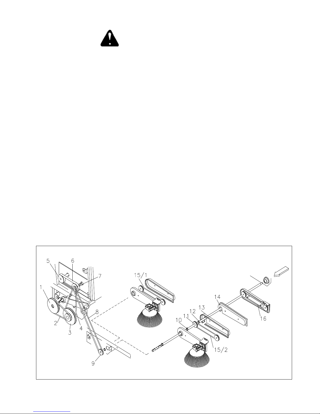
7.8 - Sustitución de las correas
Antes de efectuar cualquier tipo de intervención en
la máquina, asegurarse que la misma esté apagada y
que todas sus funciones estén desactivadas. Para
obtener este estado, colocar el interruptor a llave 5
Fig. 3 en posición OFF.
Luego de haber aflojado los tornillos que fijan el cárter superior
derecho y el inferior y/o eventuales cárteres de protección:
CORREA 2: haciendo palanca con un destornillador, sacar la
correa de la garganta de una polea y sustituirla.
CORREA 4: haciendo palanca con un destornillador, sacar la
correa de la garganta de una polea y sustituirla
ATENCIÓN: para quitar la correa 4 es necesario quitar antes la
correa 2.
CORREA 6: aflojar los dos tornillos de bloqueo y extraer las 2
poleas 5 and 7 de los árboles respectivos.
ATENCIÓN: para quitar la correa 6 es necesario quitar antes la
correa 4 y 8.
CORREA 8: haciendo palanca con un destornillador, sacar la
correa de la garganta de una polea y sustituirla.
CORREA 15/1: (Vers. Simple Cepillo lateral) haciendo palanca con
un destornillador, sacar la correa de la garganta de una polea y
sustituirla.
CORREA 15/2 - CORREA 16: ( Vers. Doble Cepillo lateral)
Luego de quitar los seeger de fijación del árbol y de las poleas,
extraer el árbol hasta que sea posible quitar la correa. Una vez
sustituida la correa, posicionar nuevamente el árbol y bloquearlo
con los seeger.
ESPAÑOL (Traducción de las instrucciones originales)
Pag. 10
Page 68

7.9 - SUSTITUCIÓN DE LOS FLAPS
Flaps laterales y posterior fijo: aflojar los tornillos que fijan el tope
de los flaps al bastidor de la máquina.
- Quitar el tope de los flaps.
- Sustituir el flap desgastado con uno nuevo.
- Colocar nuevamente el tope, bloqueándolo con los tornillos
respectivos.
Flap anterior regulable: desenganchar el perno de fijación del
cable alza flap.
- Quitar el tope.
- Sustituir el flap desgastado con uno nuevo.
- Posicionar el tope bloqueándolo con los tornillos.
- Enganchar nuevamente el cable al flap.
7.10 Sustitución y regulación
del cable del freno
Para sustituirlo, operar de la siguiente manera:
Aflojar los tornillos de fijación del frente de la máquina y de los
paragolpes y quitar el mismo.
Aflojar el borne paracable (61) colocado sobre el freno.
Extraer el cable del pedal, teniendo cuidado que, durante esta
operación, el resorte (60) de retorno del freno no se pierda.
Para volver a montarlo:
- Antes de proceder a montar el cable, aflojar los registros (40) y
engrasar el cable de acero.
- Luego de insertar el cable en el perno pasa-cable (37) situado en
el pedal del freno, hacer pasar el cable por el perno de registro (40).
- Insertar el cable en la vaina (57) y luego el resorte en el cable.
- Bloquear el cable con el borne (61).
-Bloquear la vaina con el cable mediante el borne para-vaina (55).
-Para una eventual regulación de la frenada, accionar los registros
(40) cercanos a la palanca del freno.
Antes de efectuar cualquier tipo de intervención en
la máquina, asegurarse que la misma esté apagada
y que todas sus funciones estén desactivadas. Para
obtener este estado, colocar el interruptor a llave
5 Fig. 3 en posición OFF.
7.11 - SUSTITUCIÓN Y REGULACIÓN DEL
CABLE ALZA-FLAP
Para cumplir esta operación, proceder del siguiente modo:
- Aflojar los tornillos de fijación del frente y del paragolpes de la
máquina y extraer el mismo.
- Aflojar el borne para-cable (43) colocado sobre el pedal.
- Desenganchar el perno (33) de la horquilla del flap.
- Extraer el cable (36).
Para volver a montarlo:
- Luego de haber recuperado el cable roto, la horquilla y la tuerca
(35) de tope (si aun son utilizables), volver a montar los mismos
sobre el nuevo cable alza-flap.
- Bloquear la horquilla al flap mediante el perno para horquilla (33).
- Insertar el resorte (37) en el cable y el cable en el perno guía (40).
Insertar el cable (36) en la vaina (49) y hacerlo pasar por el perno
(47).
- Insertar el cable en el borne para-cable (43) y bloquearlo.
ESPAÑOL (Traducción de las instrucciones originales)
Pag. 11
Page 69

Antes de efectuar cualquier tipo de intervención en
la máquina, asegurarse que la misma esté apagada
y que todas sus funciones estén desactivadas. Para
obtener este estado, colocar el interruptor a llave
5 Fig. 3 en posición OFF.
7.12 - Sustitución y regulación del cable alza-cepillo
central
Para sustituirlo, operar de la siguiente manera:
- Colocar la manilla (2) en posición OFF.
- Levantar el capó superior.
- Aflojar los tornillos que fijan los cárteres laterales superiores e
inferiores y quitarlos.
- Quitar el bulón de fijación manilla al soporte.
- Aflojar los tornillos (41).
- Abrir la manija (2).
- Extraer la vaina provista de cable.
- Aflojar y quitar el borne.
- Quitar el perno (9).
- Extraer la horquilla del balancín.
- Extraer el cable (6) de la vaina (5).
7.13 CAMBIO DE ACEITE DEL MOTOR
Para la frecuencia del cambio de aceite, hacer
referencia al manual del motor.
Se recuerda que esta operación debe ser efectuada con
máquina apagada y motor frío. Es indispensable hacer
cumplir dicha operación a personal calificado.
Luego de haber levantado el capó superior de la máquina y de
haber controlado que todas las funciones de la máquina estén
apagadas y que el motor no esté a una temperatura que pueda
causar peligros al operador, proceder del siguiente modo:
- Individualizado el tubo de descarga conectado al motor a
explosión, hacerlo pasar a través del agujero situado en la chapa
de cierre del espacio motor.
- Extraer la varilla de nivel de aceite motor para favorecer la salida
del aceite.
- Colocar un recipiente para la recogida del aceite agotado cerca
del tubo de descarga aceite y aflojar el tapón de cierre.
Para volver a montarlo:
- Colocar la manilla (2) en posición ON.
- Insertar el cable (6) en la vaina (5).
- Enganchar la horquilla al balancín bloqueándola con el perno (9).
- Insertar el borne en el cable bloqueándolo para que con la manilla
(2) en posición ON la longitud del cable resulte tal que el tampón
de tope toque el tope de referencia.
- Volver a colocar el borne en la manilla y ajustar los tornillos (41).
- Ajustar la manija (2) al soporte.
- Ensamblar nuevamente los cárteres laterales.
- Terminada la operación de descarga del aceite agotado, cerrar
el tubo de descarga y volver a ponerlo dentro fdel espacio motor,
colocándolo de modo que no impida ningún movimiento de los
órganos de la máquina.
- Llenar la máquina con aceite nuevo a través del tubo porta-varilla
del nivel de aceite, cuidando de medir la cantidad necesaria ( 0,7
l.) antes de efectuar dicha operación, para prevenir eventuales
daños debidos a la salida del aceite.
- Terminada la operación de llenado, insertar la varilla del nivel de
aceite y controlar con la misma que la cantidad de aceite sea
correcta.
Cerrar el capó superior de la máquina.
Ahora la máquina está lista para trabajar.
RECORDAR QUE EL ACEITE AGOTADO DEBE SER
ELIMINADO SEGÚN LAS NORMAS VIGENTES.
ESPAÑOL (Traducción de las instrucciones originales)
Pag. 12
Page 70

Antes de efectuar cualquier tipo de intervención en
la máquina, asegurarse que la misma esté apagada
y que todas sus funciones estén desactivadas. Para
obtener este estado, colocar el interruptor a llave
5 Fig. 3 en posición OFF.
7.14 - SUSTITUCION DEL MOTOVIBRADOR DEL
SACUDIDOR DE FILTRO
Para sustituir el motovibrador del sacudidor de filtro, proceder de
la siguiente manera:
1- Levantar el cajón posterior.
2- Aflojar tuerca mariposa de cierre y quitar la tapa de la caja filtro.
3-Aflojar los 4 pomos de fijación filtro.
4- Extraer el filtro de su alojamiento.
5- Aflojar los 2 tornillos de fijación cables de alimentación y
desconectar el motor.
6- Aflojar los 4 tornillos de bloqueo motor al bastidor porta-filtro
y quitar el motovibrador.
Para volver a montar el motovibrador, ejecutar las operaciones
arriba mencionadas en sentido contrario.
NOTA: RESPETAR LA POLARIDAD AL CONECTAR EL
MOTOR.
8.1 ELIMINACIÓN DE LA MÁQUINA
Este producto es un residuo especial de tipo RAEE, y
responde a los requisitos exigidos por las nuevas
directivas de protección del medio ambiente (2002/96/CE
RAEE). Debe ser eliminado por separado de los residuos
sólidos urbanos respetando las leyes y normas vigentes.
Residuo especial. No eliminar con los
residuos sólidos urbanos.
NO UTILIZAR NINGUNA PARTE QUE DEBA SER
TELIMINADA COMO PIEZA DE REPUESTO
TAMBIÉN EN ESTE CASO MANTENER FUERA DEL
ALCANCE DE LOS NIÑOS
ESPAÑOL (Traducción de las instrucciones originales)
Pag. 13
Page 71

8.2 - SCHEMA ELETTRICO 8.2 - PLANO ELÉCTRICO
30/1: Apagado del motor AZUL
50: Encendido del motor MARRÓN
15: Masa - NEGRO
30: Salida de línea + GRIS
15/54 Línea + ROJO
Relé: 12V 20/30A
Motor sacudidor de filtro: 12V
Claxon: 12V
F1: 15A
F2: 15A
F3: 15A
Intermitente: 12V
Faro: 12V
Batería: 12V 45 Ah
ESPAÑOL (Traducción de las instrucciones originales)
Pag. 14
Page 72

Par. INHOUDSOPGAVE
**** Overeenkomsten en legenda
1.1 Waarschuwingen voor de veiligheid
2.1 Identificatiekaart van de machine
2.2 Serienummer en EEG keurmerk
2.3 Technische gegevens
3.1 Inleiding
3.2 Gebruiksgebied
4.1 Uitpakken
4.2 Voorzorgsmaatregelen
4.3 Montage zijborstel
5.1 Besturingsunit
5.2 Bedieningspaneel
6.1 Startprocedure
6.2 Bedrijfsprocedure
6.3 Reinigen afvalbak
7.1 Onderhoud batterij
7.2 Verbruiksgoederen
7.3 Onderhoud filter
7.4 Vervangen filter
7.5 Afstellen dode punt verplaatsing
7.6 Vervangen middelste borstel
7.7 Vervangen zijborstel
7.8 Vervangen riemen
7.9 Vervangen flappen
7.10 Vervangen en afstellen remkabel
7.11 Vervangen en afstellen kabel optillen flap
7.12 Vervangen kabel optillen middelste borstel
7.13 Verversen motorolie
7.14 Vervangen motorbediende triller filterschudder
8.1 Afdanken van de machine
8.2 Bedradingsschema
8.3 Tabel storing-oorzaak-oplossing
NEDERLANDS (Vertaling van de oorspronkelijke aanwijzingen)
Pag. 1
Page 73

OVEREENKOMSTEN EN LEGENDA
De in deze handleiding gebruikte aanduidingen RECHTS of LINKS,
NAAR RECHTS en NAAR LINKS hebben altijd betrekking op de
bewegingsrichting van de machine.
ATTENTIE: De machine is uitgerust met een systeem voor
presentiecontrole, waardoor ze uitsluitend gestart kan worden
wanneer de bestuurder zich in de juiste werkpositie bevindt.
Dankzij dit systeem stopt de machine wanneer de bestuurder zijn
plaats verlaat.
De paragrafen voorafgegaan door dit symbool
behandelen onderwerpen die schade aan de machine
kunnen veroorzaken, indien de voorschriften
verwaarloosd worden.
De paragrafen voorafgegaan door dit symbool
OPMERKING
behandelen onderwerpen die persoonlijk letsel
kunnen veroorzaken, indien de voorschriften
verwaarloosd worden.
De paragrafen voorafgegaan door dit symbool
behandelen onderwerpen die zeer aandachtig
gelezen moeten worden.
Gebruik deze handleiding om kennis te maken met de machine en
er optimaal gebruik van te maken.
Alle paragrafen van het volgende hoofdstuk
kunnen leiden tot schade aan zaken en/of
persoonlijk letsel, indien de voorschriften niet
worden opgevolgd.
HET WORDT GEADVISEERD DE MACHINE BUITEN HET
BEREIK VAN KINDEREN TE HOUDEN.
BELANGRIJK: De fabrikant is GEENSZINS aansprakelijk voor
schade aan de machine wanneer ze niet behandeld wordt in
overeenstemming met de gebruiksbestemmingen.
De machine KAN en MAG NIET gesleept worden.
Er MAG NIET aan de machine geknoeid worden; gebeurt dit toch,
dan is de fabrikant geenszins aansprakelijk voor de correcte werking
of eventuele door de machine veroorzaakte schade aan zaken of
personen.
Wanneer de motorolie onder het toegestane peil staat zorgt een
veiligheidssysteem automatisch voor het stoppen van de motor.
Was de machine nooit met waterstralen.
Gebruik de machine niet voor het opzuigen van giftige stoffen.
Het is verboden de machine te gebruiken wanneer de hellingsgraad
meer dan 12% bedraagt.
Gebruik de machine uitsluitend in open en goed geventileerde
ruimtes.
De machine mag uitsluitend gebruikt worden op goed verlichte
plaatsen.
Bij gebruik van de machine op plaatsen waar kans op vallen van
kleine voorwerpen bestaat, moet de bediener een veiligheidshelm
dragen.
Gebruik de machine niet om kabels, bandijzer, ijzerdraad of soortgelijk
materiaal op te vegen.
Het is verboden de machine te gebruiken in de buurt van kabels,
snoeren of soortgelijk materiaal.
Start de machine niet met ingetrapt richtingspedaal; onverwacht
rijden kan schade aan zaken en/of persoonlijk letsel tot gevolg
hebben.
HET IS VERBODEN DE MACHINE TE GEBRUIKEN EN OP TE
BERGEN IN EEN OMGEVING WAAR ONTPLOFFINGSGEVAAR BESTAAT.
De machine mag uitsluitend gebruikt worden door bevoegd en
degelijk opgeleid personeel. Houd er verder rekening mee dat het
TEN STRENGSTE VERBODEN is om:
- Personen te vervoeren; Met uitzondering van de bestuurder.
- Bewegende machinedelen aan te raken.
- Delen van het machinelichaam te verwijderen wanneer de machine
ingeschakeld is;
- De ingeschakelde machine alleen te laten.
Draag altijd kleding die geschikt is voor het soort uit te voeren
werkzaamheden.
Bij gebruik in een zeer stoffige omgeving, zoals cementfabrieken,
zagerijen, werkplaatsen e.d. wordt aangeraden gebruik te maken van:
- mondkapje:
- veiligheidsbril.
- werkhandschoenen.
LAAT de machine NOOIT ACHTER terwijl de sleutel op het
bedieningspaneel steekt.
NEDERLANDS (Vertaling van de oorspronkelijke aanwijzingen)
Pag. 2
Page 74

2.2 - SERIENUMMER EN EEG KEURMERK
Controleer of de machine voorzien is van het plaatje met serienummer en EEG keurmerk, zoals weergegeven in de afbeelding.
In tegengesteld geval contact opnemen met de verkoper.
Serial number - CE marking
PLAATJE SERIENUMMER EEG KEURMERK
PLAATJE
2.3 - TECHNISCHE GEGEVENS 2.3 - TECHNICAL FEATURES
Hoofdspanning Main Power 12 V
Totaal geïnstalleerd vermogen Maximum installed power 5. 5 Hp
Overbrenging op 1 wiel Transmission Een wiel - One-wheel
Voortbewegingssnelheid Forward gear speed 0 - 6,2 Km/h
Achteruitrijsnelheid Reverse gear speed 0 - 4,6 Km/h
Schoonmaakbreedte met middelste borstel Cleaning width with main brush 700 mm
Schoonmaakbreedte met zijborstel Cleaning width with side brush 900 mm
Schoonmaakbreedte met dubbele zijborstel Cleaning width with double side brush 1100 mm
Inhoud afvalbak Capacity of the waste bin 65 Lt
Doekfilter Panel filter 4 m²
Productiviteit Productivity 3800 - 5600 m²/h
Gewicht Weight 290 Kg
Kenmerk batterij Battery 12V / 45Ah
Motorbediende triller Motovibrator 12V DC 90W
Maximale gebruikshelling Max. sloping surface allowed 12%
Pomp met variabel debiet Pump 0 - 10 cc
Hydraulische motor Hydraulic motor 98 Cm³/rpm
Geluidsdruk LpA Sound Pressure LpA 76 dB
GEMETEN GELUIDSVERMOGEN LWA MEASURED SOUND POWER LWA 90 dB
GEWAARBORGD GELUIDSVERMOGEN LWA,g GUARANTEED SOUND POWER LWA,g 91 dB
Trillingen op handen HAV Hand vibration HAV 2,3 [m/sec
(meetonzekerheden) k (measurement uncertainty) k 1,2 [m/sec
Trillingen op lichaam HBV Body vibration HBV 0,8 [m/sec
(meetonzekerheden) k (measurement uncertainty) k 0,4 [m/sec
2
]
2
]
2
]
2
]
NEDERLANDS (Vertaling van de oorspronkelijke aanwijzingen)
Pag. 3
Page 75

3.1 - INLEIDING
Deze handleiding heeft als doel om als leidraad te fungeren en bevat
praktische informatie over de beveiliging, de werking, de afstelling
en het onderhoud van uw machine. Uw machine is ontworpen en
gebouwd om optimale prestaties, comfort en werkgemak onder een
grote verscheidenheid aan omstandigheden te bieden. Uw machine
is vóór aflevering gecontroleerd in de fabriek en door onze dealer,
om te garanderen dat zij in perfecte toestand aan u wordt afgeleverd.
Om de machine in die toestand te houden of werken zonder
problemen te garanderen, moeten de periodieke
onderhoudswerkzaamheden vermeld in deze handleiding
uitgevoerd worden.
3.2 - GEBRUIKSGEBIED
De machine is UITSLUITEND bestemd voor het schoonmaken,
vegen en zuigen van droge vloeren. Elk ander gebruik kan schade
aan zaken of persoonlijk letsel tot gevolg hebben en is dus TEN
STRENGSTE VERBODEN.
4.1 - UITPAKKEN
- Pak de machine voorzichtig uit om schade te voorkomen.
Controleer wanneer de machine uitgepakt is of alle delen ervan
intact zijn. In tegengesteld geval de machine NIET gebruiken en
u onmiddellijk tot uw verkoper wenden.
- Met het oog op verpakking en transport kan het zijn dat sommige
delen en optionals apart worden geleverd; volg voor de juiste
montage de aanwijzingen op die in de volgende paragrafen van
deze handleiding beschreven staan.
4.2 - TE NEMEN VOORZORGSMAATREGELEN ALVORENS DE MACHINE IN
BEDRIJF TE STELLEN
Met het oog op het transport is/zijn de zijborstel/s niet in de
werkstand gemonteerd. Monteer ze zoals beschreven staat in
paragraaf 4.3.
- Vul de brandstoftank met GROENE loodvrije benzine.
- Controleer het peil van de motorolie.
- Controleer het oliepeil van het hydraulisch systeem.
- Controleer of de startbatterij geladen is.
- Sluit de batterij aan en houd rekening met de polariteit.
Raadpleeg de bijgesloten specifieke handleiding voor aanwijzingen
omtrent de explosiemotor.
4.3 - MONTAGE ZIJBORSTEL
Ga als volgt te werk om de zijborstel in de juiste werkstand aan te
brengen:
1 Zet de hendel voor optillen van de borstel 5 7 5-A Afb.2 in de
stand OFF.
2 Draai de schroef van de motoras van de zijborstel los.
3 Verwijder de spieborging.
4 Plaats de borstel met flens op de as.
5 Draai de borgschroef weer vast.
- Inhoud van de verpakking:
- 1 Machine
- 1 of 2 Zijborstels
- 1 Startsleutel
- 1 Handleiding
- 1 Boekje met onderdelen.
- 1 Handleiding Explosiemotor
- 1 Conformiteitsverklaring
- 1 Garantiecertificaat
Wanneer een van bovengenoemde delen ontbreekt dient u zich tot
de verkoper te wenden.
OPMERKING
NEDERLANDS (Vertaling van de oorspronkelijke aanwijzingen)
Om kwijtraken tijdens het transport te voorkomen,
is de startsleutel opgeborgen in het zakje met de
technische documentatie.
Controleer of het verpakkingsmateriaal (zakjes,
kartonnen dozen, pallets, haken e.d.) goed
opgeborgen wordt en buiten het bereik van
kinderen.
Afb.1
Pag. 4
Page 76

5.1 - BESTURINGSUNIT
5.2 - BEDIENINGSPANEEL
Afb.2
1: Pedaal vergrendelen rem ( Parkeerrem)
Door dit pedaal samen met het pedaal van de bedrijfsrem 2 in te
drukken wordt de bedrijfsrem vergrendeld en de parkeerrem
ingeschakeld. Om de parkeerrem te ontgrendelen het pedaal van de
bedrijfsrem 2 indrukken; hierdoor wordt het pedaal voor
vergrendelen van de rem in de ruststand gezet.
2: Pedaal bedrijfsrem
Bij bedienen van dit pedaal stopt de machine tijdens het werken.
3: Pedaal optillen flap
Bedien dit pedaal wanneer er grote en lichte voorwerpen opgeveegd
moeten worden; maak geen onnodig gebruik van dit pedaal.
4: Pedaal voor richtingkeuze
Door dit pedaal te bedienen wordt de rijrichting en de betreffende
snelheid gekozen.
5: Bedieningshendel Rechter zijborstel
Trek aan deze hendel en zet hem omlaag om de borstel in de
bedrijfsstand te plaatsen. Zet na afloop van het werk de hendel in
de vorige stand.
5.A: Bedieningshendel Linker zijborstel
Voor modellen met dubbele zijborstel zoals hierboven beschreven.
Afb.3
1: Starter
Hendel voor activeren van luchttoevoer voor starten bij koude
motor.
2: Hendel regelen toerental motor
Door deze hendel te bedienen kan het toerental van de motor
geregeld worden.
3: Urenteller
Geeft het totaal aantal bedrijfsuren van de machine aan.
4: Controlelampje spanning
Dit geeft aan dat er spanning op de machine staat.
5: Startsleutel
Voor in- en uitschakelen van alle machinefuncties.
6: Drukknop voor inschakelen van claxon.
Bij drukken op deze knop wordt de claxon in werking gesteld.
7: Drukknop voor activeren motorbediende triller filter.
Bij drukken op deze knop wordt de motorbediende triller voor
reinigen van het filter geactiveerd (Zie Handl. Filter).
6: Bypass voor rijden in noodsituatie
Hiermee kan de machine, indien nodig, met uitgeschakelde motor
verplaatst worden. Draai de BYPASS knop een 1/2 draai in de
richting 0 MAN om de machine met uitgeschakelde motor te
verplaatsen.
7: Bedieningshendel middelste borstel
Door de hendel in de stand ON te zetten wordt de middelste borstel
in de werkstand opgesteld. Zet na afloop van het werk de hendel
in de stand OFF.
8: Hendel openen luchttoevoer
Voor openen en sluiten van de luchtstroom voor stofaanzuiging.
9: Hendel stroomonderbreking motor (Koppeling)
Hiermee worden alle motorfuncties tijdens de startfase
uitgeschakeld.
NEDERLANDS (Vertaling van de oorspronkelijke aanwijzingen)
Pag. 5
Page 77

6.1 - STARTPROCEDURE
- Ga op de stoel zitten.
- Zet de gashendel 2 Afb.3 in de stand START.
- Trek aan de hendel van de starter 1 Afb.3
- Plaats de koppelingshendel 9 Afb 2 in de stand 1 -START
POSITIE en laat hem in die stand staan terwijl u de sleutelschakelaar
5 Afb.3 bedient. Zet de startschakelaar in de stand START en laat
hem staan totdat de motor start.
N.B. Laat de startmotor telkens niet langer dan 5 seconden draaien.
Indien de motor niet start de sleutel loslaten en ongeveer 10
seconden wachten alvorens de startmotor opnieuw in te schakelen.
Bij starten van de motor de sleutel in de stand ON zetten.
Zodra de motor gestart is de koppelingshendel 9 Afb.2 loslaten.
Bij bedienen van het versnellingspedaal 4 Afb.2 begint de machine
te rijden.
Bij indrukken van het RECHTER pedaal rijdt de machine VOORUIT.
Bij indrukken van het LINKER pedaal rijdt de machine ACHTERUIT.
ATTENTIE: Controleer na afloop van het werk of de middelste en
de zijborstel in de stand OFF staan en de grond niet
raken, of de parkeerrem is ingeschakeld en de
startsleutel verwijderd is.
6.2 - BEDRIJFSPROCEDURE
6.3 - SCHOONMAKEN VAN DE ACHTERSTE
AFVALBAK
Ga als volgt te werk om de afvalbak leeg te maken:
- Maak de vergrendeling van de bak los.
- Trek aan de handvaten van de achterste bak om hem te verwijderen.
- Sleep de bak (die voorzien is van wielen) naar de ruimte waar het
afval wordt verzameld.
- Maak de bak leeg en voorkom beschadiging van de bak.
- Plaats de bak weer in de betreffende ruimte op de machine.
- Maak de bak weer dicht aan de achterkant.
N.B. Op grond van het gewicht van de volle bak
wordt aangeraden het werk met z’n tweeën uit te
voeren.
ATTENTIE: Verwerk het afval in overeenstemming
met de geldende wetsvoorschriften.
Nadat de machine gestart is zoals hierboven beschreven werd, naar
eigen behoeften verder gaan en de middelste borstel laten zakken
door de hendel 7 Afb.2 in de stand ON te zetten.
De zijborstel laten zakken (indien nodig) (of beide zijborstels voor
de versie met Dubbele Borstel) met de bedieningshendels 5 - 5A
Afb 2.
Voor het geval de borstels tijdens het werk stof doen opwaaien wordt
geadviseerd de zuiging in te schakelen met de hendel 8 Afb 2.
Om grote en lichtgewicht afvalresten op te vegen het pedaal voor
optillen van de flap 3 Afb.2 intrappen. Houd het pedaal voor optillen
van de flap niet onnodig ingedrukt.
Zorg er voor dat de machine altijd in prima staat verkeert met het oog
op optimaal en veilig gebruik.
Hiertoe moeten alle aanwijzingen van de paragraaf Gewoon
Onderhoud zeer nauwkeurig worden opgevolgd.
Om de machine uit te schakelen de hendel 2 Afb.3 in de minimumstand
zetten en de sleutel 5 Afb.3 op OFF zetten. Het wordt aangeraden
om te werken terwijl de motor met het maximumtoerental draait (
hendel 2 Afb.3 ).
Indien de machine rijdt wanneer het richtingspedaal niet ingedrukt
is moet het dode punt voor verplaatsing afgesteld worden zoals
vermeld in Par.7.5.
NEDERLANDS (Vertaling van de oorspronkelijke aanwijzingen)
Pag. 6
Page 78

C O N T R O L L I C H E C K
Controllare olio impianto idraulico Check the hydraulic system's oil
x
x
Controllare l'usura delle cinghie The belts for slackening
x
Registrare il freno Adjust the brake's cable
x
Controllare il serraggio di dadi e viti The tightness of nuts and screws
x
Controllare lo stato delle spazzole The brushes for wear
x
Controllare la tenuta delle guarnizioni The gaskets for wear and leakages
x
Controllare il funzionamento di tutte le funzioni If all the functions are in working order
x
x
Ingrassare la catena dello sterzo Grase the steering chain up
x
GEWOON ONDERHOUD
ALLE GEWONE EN EXTRA ONDERHOUDSWERKZAAMHEDEN MOETEN UITGEVOERD WORDEN DOOR PERSONEEL VAN
EEN ERKEND TECHNISCH SERVICECENTRUM. HET VERDIENT AANBEVELING UITSLUITEND ORIGINELE ONDERDELEN TE
GEBRUIKEN. ATTENTIE: VOER GEEN CONTROLE- OF ONDERHOUDSWERKZAAMHEDEN UIT NA EEN WERKCYCLUS: LAAT
DE MACHINE ALTIJD EERST AFKOELEN.
VUL NOOIT BRANDSTOF BIJ ALS DE MACHINE NIET VOLLEDIG AFGEKOELD IS. VOOR ONDERHOUD VAN DE
EXPLOSIEMOTOR DE SPECIFIEKE HANDLEIDING RAADPLEGEN.
C O N T R O L E S
Het oliepeil van het hydraulisch systeem controleren
De riemen op slijtage controleren
De rem afstellen
Bevestiging van moeren en schroeven controleren
Toestand van de borstels controleren
Pakkingen controleren
Werking van alle functies controleren
Stuurketting smeren
7.1 - ONDERHOUD BATTERIJ
De batterij moet altijd schoon en droog zijn; controleer
of polen en klemmen altijd goed schoon zijn. Verwijder
regelmatig de doppen en controleer het electrolytpeil;
vul bij met gedestilleerd water indien nodig. Denk
eraan dat de ruimte waar dit gebeurt van goede
ventilatie voorzien moet zijn. Blijf uit de buurt met open vuur en rook
niet.
Bij aflevering
On delivery
Elke 10 uur
Every 10 hours
Elke 50 uur
Every 50 hours
Elke 100 uur
Every 100 hours
7.2 - VERBRUIKSGOEDEREN
GROENE benzine Inh. motortank: 2.5 Liter
NEDERLANDS (Vertaling van de oorspronkelijke aanwijzingen)
Olie SEA 10W-30 Inh. motortank: 0.6 Liter
Olie SEA 15W-50 Inh. hydraulisch systeem tankniveau
Pag. 7
Page 79

7.3 - ONDERHOUD VAN HET FILTER
Het filter is van het grootste belang voor de goede werking van de
machine.
Correct uitgevoerd onderhoud zorgt voor optimaal rendement van
de machine.
Het filter kan op twee manieren schoongemaakt worden:
1 – Met behulp van de elektrische filterschudder
Hij maakt deel uit van de machine en zorgt ervoor dat het filter met
een eenvoudig gebaar altijd perfect schoon is. Alvorens de
filterschudder te bedienen eerst de hendel voor luchttoevoer 8
Afb.2 sluiten. Druk hiertoe op de knop 7 Afb.3 en houd hem enkele
seconden ingedrukt. Doe dit 4 à 5 keer achter elkaar.
Denk eraan dat hoe beter het filter wordt gereinigd, des te beter de
schoonmaakresultaten zijn. Het wordt geadviseerd het filter na
elke werkcyclus te reinigen.
STOFFIGE OMGEVING: Bij gebruik in een zeer
OPMERKING
2 - Handmatig reinigen van het filter
Mocht de reiniging van het filter met behulp van de filterschudder
te wensen overlaten, maak het dan met de hand schoon (in elk geval
elke 20 uur).
Alvorens werkzaamheden aan de machine uit te voeren altijd
controleren of ze uitgeschakeld is en alle functies gedeactiveerd
zijn; zet de sleutelschakelaar 5 Afb.3 hiertoe in de stand OFF.
Naast geregeld gebruik van de filterschudder wordt geadviseerd
het filter als volgt schoon te maken met het oog op nog betere
reiniging:
1 Til de kap onder de bestuurdersstoel op.
2 Draai de vleugelmoer van het deksel van het filterhuis los.
3 Verwijder het deksel van het filterhuis.
stoffige omgeving (zoals kolenhandel, magazijnen
waar voertuigen af- en aanrijden e.d.) moet de
filterschudder vaker gebruikt worden.
Plaats het filter zoals vermeld staat op
het etiket ervan.
Paneelfilter
Vakkenfilter
OPMERKING
Let er bij bevestigen van het filter op dat filter en
pakkingen perfect aansluiten.
ATTENTIE Dank het gebruikte filter af in overeenstemming met de geldende wetsvoorschriften.
7.5 - AFSTELLEN DODE PUNT
Wanneer de machine rijdt ook zonder dat het keuzepedaal 4 Afb.2
ingedrukt is moet het dode punt als volgt afgesteld worden:
Blaas perslucht op het filter in de richting van de afvalbak, zodat
stof en eventuele vuilresten in de bak terechtkomen.
7.4 - VERVANGEN VAN HET FILTER
Het filter moet ongeveer elke 200 uur vervangen worden: ga hierbij
als volgt te werk:
1 Til de kap onder de bestuurdersstoel op.
2 Draai de vleugelmoer van het deksel van het filterhuis los.
3 Verwijder het deksel van het filterhuis.
4 Ontgrendel de hendel (1) (Paneelfilter).
5 Verwijder het frame (2) waarop de motorbediende triller
bevestigd is (Paneelfilter)
6 Verwijder het filter uit het filterframe (Paneelfilter).
7 - Draai de 4 bouten los (Vakkenfilter).
8 - Maak de stekker van de filterschudder los (Vakkenfilter).
9 - Verwijder het filter uit zijn zitting (Vakkenfilter).
10 - Reinig het filter grondig met een stofzuiger of vervang het
(Vakkenfilter).
Ga in omgekeerde volgorde te werk om het nieuwe filter weer op de
machine aan te brengen.
NEDERLANDS (Vertaling van de oorspronkelijke aanwijzingen)
- Draai de tegenmoer 1 nabij de vasthaakklem los.
- Stel met schroef 2 zodanig af tot het dode punt van voortbeweging
wordt gevonden.
- Draai de tegenmoer 1 weer vast.
Pag. 8
Page 80

7.6 - VERVANGEN MIDDELSTE BORSTEL
Prima di efAlvorens werkzaamheden aan de machine uit te
voeren altijd controleren of ze uitgeschakeld is en alle functies
gedeactiveerd zijn. Zet hiertoe de sleutelschakelaar 3 Afb.3 in
de stand OFF. Zet de bedieningshendel van de middelste
borstel 6 Afb.2 in de stand OFF.
1 Draai de bevestigingsschroeven van het machinelichaam linksonder los.
2 Draai de bevestigingsschroef van de borstelarm los en verwijder de arm.
3 Verwijder de veer van de borstelas..
4 Draai de 4 bevestigingsschroeven van de sluiting van de borstelruimte los
en neem hem weg.
5 Verwijder flens en middelste borstel. Breng de nieuwe borstel zodanig aan
dat de borstelharen het afval naar het midden van de borstel toe vegen.
Ga in omgekeerde volgorde te werk om de nieuwe borstel op de machine
te plaatsen.
Afstellen middelste borstel:
De middelste borstel is van het grootste belang voor optimaal rendement van
de machine. Goede afstelling ervan leidt tot optimale resultaten in zeer korte
tijd. Bij aflevering zijn alle afstellingen op de machine uitgevoerd; stel af
wanneer de borstel versleten is. Ga als volgt te werk: Draai het machinelichaam
Rechtsboven en –onder los. Plaats de hendel 6 Afb.2 in de stand ON. Draai
de stift 10 en de tegenmoer van de borgschroef iets los. Controleer of de
draad niet gespannen is en er voldoende speling is om de stopper af te stellen.
In tegengesteld geval de stelschroef 7 afstellen tot de vereiste speling is
verkregen. Stel de stopper met de tegenmoer zodanig af dat de speling tussen
stopper en stop ongeveer 4/5 mm bedraagt. Zet tegenmoeren en stift voor
hulsvergrendeling weer vast.
7.7 - VERVANGEN ZIJBORSTEL
Zet de bedieningshendel van de zijborstel 5 (5A) Afb.2 in de
stand OFF. Draai de drie schroeven los waarmee de zijborstel
aan de meeneemflens is bevestigd. Verwijder de borstel en
vervang hem door een nieuwe. Draai de drie schroeven waarmee
de zijborstel bevestigd is weer vast. De machine is nu gereed
om weer ingeschakeld te worden.
Afstellen zijborstel:
De zijborstel heeft als functie het te verzamelen materiaal naar het midden van
de machine te vegen.
De optimale stand om dit te kunnen doen moet zodanig zijn dat de vloer heel
even aangeraakt wordt. Ga als volgt te werk om de druk van de borstel te
verhogen of te verlagen:
- Zet de zijborstel in de werkstand ON.
- Draai de twee stelschroeven los onder de knop voor het optillen van de
borstel.
- Zet de borstel met de hand in de gewenste stand.
- Zet de stelschroeven vast.
- Zet de zijborstel in de ruststand OFF.
NEDERLANDS (Vertaling van de oorspronkelijke aanwijzingen)
Pag. 9
Page 81

7.8 - VERVANGEN RIEMEN
Alvorens werkzaamheden aan de machine uit te voeren
altijd controleren of ze uitgeschakeld is en alle functies
gedeactiveerd zijn; zet de sleutelschakelaar 5 Afb.3
hiertoe in de stand OFF.
Draai eerst de schroeven los waarmee het machinelichaam
rechtsboven en onder en/of eventuele beschermende delen bevestigd
zijn:
RIEM 2: Verwijder de riem met behulp van een schroevendraaier uit
de gleuf van de meeneemschijf en vervang de riem.
RIEM 4: Verwijder de riem met behulp van een schroevendraaier uit
de gleuf van de meeneemschijf en vervang de riem.
ATTENTIE: om riem 4 te kunnen verwijderen moet eerst riem 2
weggehaald worden.
RIEM 6: Draai de twee stelschroeven los en verwijder de 2
meeneemschijven 5 en 7 van de betreffende assen.
ATTENTIE: om riem 6 te kunnen verwijderen moet eerst riem 4
en riem 8 weggehaald worden.
RIEM 8: Verwijder de riem met behulp van een schroevendraaier uit
de gleuf van de meeneemschijf en vervang de riem.
RIEM 15/1 (Vers. Een Enkele Zijborstel): Verwijder de riem met behulp
van een schroevendraaier uit de gleuf van de meeneemschijf en
vervang de riem.
RIEM 15/2 - RIEM 16 (Vers. Dubbele Zijborstel) Verwijder eerst de
Seegerringen waarmee as en meeneemschijven bevestigd zijn en neem
de as zover weg dat de riem verwijderd kan worden. Nadat de riem
vervangen is de as weer aanbrengen en met de betreffende Seegerringen
vastzetten.
NEDERLANDS (Vertaling van de oorspronkelijke aanwijzingen)
Pag. 10
Page 82

7.9 - VERVANGEN VAN DE FLAPPEN
Zijflappen en vaste achterflap: draai de schroeven los waarmee de
flapstop aan het machineframe is bevestigd.
- Verwijder de flapstop.
- Vervang de versleten flap door een nieuwe.
- Breng de flapstop weer aan met de eerder verwijderde schroeven.
Afstelbare voorflap: maak de bevestigingsklem los van de kabel
voor het optillen van de flap.
- Verwijder de flapstop.
- Vervang de versleten flap door een nieuwe.
- Breng de flapstop weer aan en zet de schroeven vast.
- Maak de kabel weer aan de flap vast.
7.10 - VERVANGEN EN AFSTELLEN
REMKABEL
Ga als volgt te werk om de remkabel te vervangen:
- Draai de schroeven voor bevestiging van neus en bumpers los
en haal ze van de machine.
- Draai de kabelklem (61) op de rem los.
- Trek de kabel uit het pedaal en let erop dat de terugslagveer (60)
van de rem niet kwijtraakt.
Alvorens werkzaamheden aan de machine uit te
voeren altijd controleren of ze uitgeschakeld is en
alle functies gedeactiveerd zijn; zet de
sleutelschakelaar 5 Afb.3 hiertoe in de stand OFF.
7.11 - VERVANGEN EN AFSTELLEN KABEL
OPTILLEN FLAP
Ga als volgt te werk om de kabel voor optillen van de flap te
vervangen:
- Draai de schroeven voor bevestiging van neus en bumpers los
en haal ze van de machine.
- Draai de kabelklem (43) op het pedaal los.
- Maak de klem (33) van de flapvork los.
- Trek de kabel (36) weg.
Voor hermontage
- Haal vork en stopmoer (35) van de kapotte kabel (indien ze nog
bruikbaar zijn) en plaats ze op de nieuwe kabel voor optillen van
de flap.
- Vergrendel de vork aan de flap met behulp van de klem (33).
- Schuif de veer 37 op de kabel 36. Steek de kabel eerst in de leipen
40, dan in de huls 49 en vervolgens in de pen 47.
- Schuif de kabel in de betreffende kabelklem (43) en zet hem vast.
Voor hermontage:
- Alvorens de kabel opnieuw te monteren eerst de stelschroeven
(40) losdraaien en de staalkabel invetten.
- Schuif de kabel eerst in de pen van de kabelklem (37) op het
rempedaal en steek de kabel in de stelpen (40).
- Steek de kabel in de huls (57) en plaats daarna de veer op de kabel.
- Zet de kabel vast met de klem (61).
- Zet de huls met kabel in de betreffende hulsklem (55).
- Voor afstellen van de remwerking de stelschroeven (40) in de
buurt van de remhendel bedienen.
NEDERLANDS (Vertaling van de oorspronkelijke aanwijzingen)
Pag. 11
Page 83

Alvorens werkzaamheden aan de machine uit te
voeren altijd controleren of ze uitgeschakeld is
en alle functies gedeactiveerd zijn; zet de
sleutelschakelaar 5 Afb.3 hiertoe in de stand
OFF.
7.12 -VERVANGEN EN AFSTELLEN VAN KA-
BEL OPTILLEN MIDDELSTE BORSTEL
Ga als volgt te werk om de kabel voor optillen van de middelste
borstel te vervangen:
7.13 - VERVERSEN MOTOROLIE
Raadpleeg de handleiding van de motor voor de
regelmaat waarmee de motorolie ververst moet
worden.
Denk eraan dat tijdens het verversen van olie de
machine uitgeschakeld en de motor afgekoeld
moet zijn. Laat dit over aan vakmensen.
Til de bovenste machinekap op, controleer of alle machinefuncties
uitgeschakeld zijn en de motortemperatuur geen gevaar meer
oplevert: ga daarna te werk als volgt:
- Zet handgreep (2) in de stand OFF.
- Til de bovenste kap op.
- Draai de schroeven los waarmee het machinelichaam aan bovenen onderzijkant bevestigd is en verwijder het.
- Verwijder de bout waarmee de handgreep aan de steun is bevestigd.
- Draai de schroeven (41) los.
- Maak de handgreep (2) open.
- Verwijder de huls voorzien van de kabel.
- Draai de klem los en verwijder ze.
- Verwijder de klem (9).
- Haal de vork van de tuimelaar.
- Trek de kabel (6) uit de huls (5).
Voor hermontage
- Zet de handgreep (2) in de stand ON.
- Schuif de kabel (6) in de voering (5).
- Haak de vork vast aan de tuimelaar en zet ze vast met de klem (9).
- Zet de klem zodanig op de kabel dat met handgreep (2) in de stand
ON de lengte van de kabel resulteert in aanraken van
aanslagstopper en referentiestop.
- Plaats de klem weer in de handgreep en draai de schroeven (41)
vast.
- Schroef de handgreep (2) weer vast op de steun.
- Monteer de machinelichamen aan de zijkant weer.
- Zoek de op de explosiemotor aangesloten olieafvoerleiding en
steek ze door de opening in de sluitplaat van de motorruimte.
- Steek de oliepeilstaaf door de motor om afvoer van de olie te
vergemakkelijken.
- Zet een bakje in de buurt van de afvoerleiding om de olie op te
vangen en draai de dop los.
- Sluit de afvoerleiding nadat de olie is afgetapt en plaats ze weer
in de motorruimte: zorg ervoor dat de machinedelen geen hinder
bij het bewegen ondervinden.
- Meet eerst de nodige hoeveelheid (0,7 l.) af (om overlopen van
olie te voorkomen) en vul de leiding met peilstaaf met nieuwe olie.
- Steek na het vullen de peilstaaf weer op zijn plaats om te controleren
of de olie tot het juiste peil reikt. Sluit de bovenste kap van de
machine. De machine is nu gereed om weer gestart te worden.
DENK ERAAN DAT GEBRUIKTE OLIE VERWERKT MOET
WORDEN IN OVEREENSTEMMING MET DE GELDENDE
WETSVOORSCHRIFTEN.
NEDERLANDS (Vertaling van de oorspronkelijke aanwijzingen)
Pag. 12
Page 84

Alvorens werkzaamheden aan de machine uit te
voeren altijd controleren of ze uitgeschakeld is en
alle functies gedeactiveerd zijn; zet de
sleutelschakelaar 5 Afb.3 hiertoe in de stand OFF.
7.14 -VERVANGEN MOTORBEDIENDE
TRILLER FILTERSCHUDDER
Ga als volgt te werk om de motorbediende triller van de filterschudder
te vervangen:
1 Til de bovenste kap op.
2 Draai de vleugelmoer los en verwijder het deksel van het filterhuis.
3 Draai de 4 bevestigingsknoppen van het filter los.
4 Verwijder het filter uit zijn zitting.
5 Draai de 2 bevestigingsschroeven van de stroomkabels los en
koppel de motor af.
6 Draai de 4 schroeven los waarmee de motor aan het filterframe is
bevestigd en verwijder de motorbediende triller.
Ga in omgekeerde volgorde te werk om de motorbediende triller te
monteren.
BELANGRIJK: BIJ HET AANSLUITEN VAN DE MOTOR DE
POLARITEIT IN ACHT NEMEN.
8.1 - AFDANKEN VAN DE MACHINE
Dit product is speciaal afval van het type RAEE, en voldoet
aan de vereisten van de nieuwe richtlijnen
ter bescherming van het milieu (2002/96/CE
RAEE). Het moet apart van het normale
afval verwerkt worden, met inachtneming
van de geldende wetten en voorschriften.
Speciaal afval. Niet verwerken
samen met normaal afval.
Afgedankte delen NIET als reserveonderdeel gebruiken.
HOUD ZE BUITEN HET BEREIK VAN KINDEREN.
NEDERLANDS (Vertaling van de oorspronkelijke aanwijzingen)
Pag. 13
Page 85

8.2 - BEDRADINGSSCHEMA 8.2 - WIRING DIAGRAM
30/1: Uitschakelen motor BLAUW
50: Inschakelen motor BRUIN
15: Massa - ZWART
30: Uitgang lijn + GRIJS
15/54: Lijn + ROOD
Relais: 12V 20/30A
Motor filterschudder: 12V
Claxon: 12V
F1: 15A
F2: 15A
F3: 15A
Intermitt.: 12V
Koplamp: 12V
Batterij: 12V 45A
NEDERLANDS (Vertaling van de oorspronkelijke aanwijzingen)
Pag. 14
Page 86

8.3 - TABEL STORING-OORZAAK-OPLOSSING TROUBLESHOOTING
STORING FAULT OORZAAK CAUSE OPLOSSING REMEDY
De middelste borstel draait niet
The main brush is not spinning
Riem is kapot The belt is broken Vervangen Replace
De zijborstel draait niet
The side brush is not spinning
Riem is kapot The belt is broken Vervangen Replace
De borstels verslijten te snel
The brushes wear out too quickly
Borstel zit te laag The brushes are too low Afstellen Adjust
Er komt tijdens het werken stof vrij
Dust forms during operation
Zijflappen versleten The flaps are worn Vervangen Replace
Filter verstopt Clogged filter Schoonmaken Clear
Motorbediende triller van filterschudder
werkt niet
The suction motor does not work
Motor doorgebrand The motor has burnt out Vervangen Replace
Zekering doorgebrand The fuse has burnt out Vervangen Replace
Draad zit los The wire is dosconnected Controleren Check
Relais doorgebrand The relay has burnt out Vervangen Replace
Schakelaar kapot The switch is broken Vervangen Replace
De machine start niet
The machine does not turn ON
Batterijen leeg The battery is discharged Opladen Recharge
Geen benzine There is no petrol Vullen Fill
Geen motorolie There is no engine's oil Vullen Fill
Schakelaar presentie defect The switch is broken Vervangen Replace
Bestuurder niet op zijn plaats Operator not in work position Op stoel gaan zitten Sit on the seat
Koppeling niet ingeschakeld Clutch insert Inschakelen Insert
NEDERLANDS (Vertaling van de oorspronkelijke aanwijzingen)
Pag. 15
Page 87

Pág. 2
PORTUGUÊS(Tradução das instruções originais)
Par.
*** Convenções e legenda
1.1 Alertas de segurança
2.1 Placa de identificação da máquina
2.2 Número de série e marca CE
2.3 Características técnicas
3.1 Introdução
3.2 Âmbito de utilização
4.1 Desempacotamento
4.2 Precauções
4.3 Montagem da escova lateral
5.1 Grupo de comandos
5.2 Painel de instrumentos
6.1 Procedimento de arranque
6.2 Procedimento de funcionamento
6.3 Limpeza do depósito
7.1 Manutenção da bateria
7.2 Consumíveis
7.3 Manutenção do filtro
7.4 Substituição do filtro
7.5 Regulação do ponto morto de deslocação
7.6 Substituição da escova central
7.7 Substituição da escova lateral
7.8 Substituição das correias
7.9 Substituição dos flaps
7.10 Substituição e regulação do cabo do travão
7.11 Substituição e regulação do cabo de elevação do flap
7.12 Substituição do cabo de elevação da escova central
7.13 Mudança do óleo do motor
7.14 Substituição do motovibrador do dispositivo de sacudir o filtro
8.1 Eliminação da máquina
8.2. Esquema eléctrico
8.4 Tabela de falhas/causas/soluções
ÍNDICE
Page 88

Pág. 3
PORTUGUÊS(Tradução das instruções originais)
O conteúdo de todos os parágrafos do capítulo
seguinte pode dar origem, caso não seja respeitado,
a danos materiais e ferimentos pessoais.
RECOMENDA-SE QUE A MÁQUINA ESTEJA SEMPRE
FORA DO ALCANCE DAS CRIANÇAS.
IMPORTANTE: O fabricante não pode ser considerado respon-
sável por danos provocados pela máquina, caso esta seja utilizada
de modo não conforme com a utilização prevista.
A máquina NÃO PODE e NÃO DEVE SER arrastada.
A máquina NÃO DEVE ser sujeita a nenhum tipo de modificação,
caso contrário o fabricante declina qualquer responsabilidade
pelo seu funcionamento corrigido ou por eventuais danos materiais ou pessoais provocados pela própria máquina.
A máquina deve ser utilizada apenas por pessoal autorizado e com
formação adequada. A propósito, lembramos que é ABSOLU-
TAMENTE PROIBIDO:
- Transportar pessoas. Excluído o condutor.
- Tocar nas partes em movimento da máquina.
- Retirar os cárteres de protecção após o arranque da máquina.
- Abandonar a máquina ligada.
É indispensável ter vestuário adequado ao tipo de trabalho que se
executa.
No caso de se estar a trabalhar numa zona com muito pó como, por
ex., uma fábrica de cimento, uma serração, estaleiros de obras,
etc., é aconselhável utilizar:
- máscara.
- óculos protectores.
- luvas.
NUNCA ABANDONE a máquina com a chave de ligação
inserida no painel de controlo.
ATENÇÃO: A máquina está equipada com um dispositivo de
presença, o qual permite a sua deslocação apenas se o operador se
encontrar na posição de trabalho correcta.
O dispositivo pára a máquina quando o operador se levantar do
assento.
Se o nível de óleo do motor descer abaixo do mínimo permitido,
um sistema de segurança pára automaticamente o motor.
Nunca lave a máquina com jactos de água.
A máquina não deve ser utilizada para aspirar substâncias tóxicas.
É proibido utilizar a máquina em superfícies com inclinação
superior a 12%.
Utilize a máquina unicamente em locais abertos e ventilados.
A máquina só pode trabalhar em locais iluminados.
No caso da máquina ser utilizada num local onde haja o perigo de
queda de pequenos objectos, o operador deve colocar o capacete
de protecção.
Não utilize a máquina para recolher cabos, cintas de
encaixotamento, fio metálico ou materiais similares.
É proibido utilizar a máquina na proximidade de cabos, fios ou
materiais similares.
Não efectue o arranque da máquina com o pedal do acelerador
premido, já que a sua partida súbita poderia causar danos materiais
e/ou pessoais.
É PROIBIDA A UTILIZAÇÃO E O ARMAZENAMENTO
EM AMBIENTES POTENCIALMENTE EXPLOSIVOS.
As eventuais indicações de DIREITA e ESQUERDA, SENTIDO
DOS PONTEIROS DO RELÓGIO e SENTIDO CONTRÁRIO AOS PONTEIROS DO RELÓGIO, que constam deste
manual, referem-se sempre ao sentido de avanço da máquina.
Os parágrafos precedidos deste símbolo referem-se a
aspectos que, caso não sejam cumpridos, podem provocar danos na máquina.
Os parágrafos precedidos deste símbolo referem-se a
aspectos que, caso não sejam cumpridos, podem implicar lesões.
Os parágrafos precedidos deste símbolo referem-se a
aspectos que devem ser lidos com muita atenção.
Utilize este manual para ficar a conhecer as características da
máquina e para compreender como tirar dela o máximo partido.
CONVENÇÕES E LEGENDA
Page 89

Pág. 4
PORTUGUÊS(Tradução das instruções originais)
Serial number - CE marking
2.2 NÚMERO DE SÉRIE – MARCA CE
Certifique-se de que a máquina dispõe de uma etiqueta contendo o número de série e a marca CE situada no local indicado na figura.
Caso contrário, avise imediatamente o revendedor.
2.3 CARACTERÍSTICAS TÉCNICAS 2.3 TECHNICAL FEATURES
Tensão principal Main Power 12 V
Potência máxima total instalada Maximum installed power 5. 5 Hp
Transmissão a 1 roda Transmission Uma roda - One-wheel
Velocidade de avanço Forward gear speed 0 - 6,2 Km/h
Velocidade de marcha-atrás Reverse gear speed 0 - 4,6 Km/h
Largura de limpeza com escova central Cleaning width with main brush 700 mm
Largura de limpeza com escova lateral Cleaning width with side brush 900 mm
Largura de limpeza com escova lateral dupla Cleaning width with double side brush 1100 mm
Capacidade do depósito de resíduos Capacity of the waste bin 65 Lt
Filtro Panel filter 4 m²
Produtividade Productivity 3800 - 5600 m²/h
Peso Weight 290 Kg
Bateria Battery 12V / 45Ah
Motovibrador Motovibrator 12V DC 90W
Inclinação máxima de utilização Max. sloping surface allowed 12%
Bomba de capacidade variável Pump 0 - 10 cc
Motor hidráulico Hydraulic motor 98 Cm³/rpm
Pressão sonora LpA Sound Pressure LpA 76 dB
POTÊNCIA SONORA MEDIDA LWA MEASURED SOUND POWERLWA 90 dB
POTÊNCIA SONORA GARANTIDA LWA,g GUARANTEED SOUND POWER LWA,g 91 dB
Vibrações na mãoHAV Hand vibration HAV 2,3 [m/sec
2
]
(incertezas de medição) k (measurement uncertainty) k 1,2 [m/sec
2
]
Vibrações no corpo HBV Body vibration HBV 0,8 [m/sec
2
]
(incertezas de medição) k (measurement uncertainty) k 0,4[ m/sec
2
]
ETIQUETA NÚMERO DE SÉRIE MARCA CE
Page 90

Pág. 5
PORTUGUÊS(Tradução das instruções originais)
3.1 INTRODUÇÃO
O presente manual de instruções tem por objectivo servir de guia
e conter as informações práticas para a segurança, o funcionamento, a afinação e a manutenção da máquina. A máquina foi projectada e fabricada para fornecer prestações optimizadas, conforto e
facilidade de trabalho, nas condições mais variáveis. Antes da
entrega, a máquina foi examinada na fábrica e pelo nosso concessionário, para garantir que lhe seria entregue em perfeitas condições. Para manter a máquina nessas condições ou assegurar um
trabalho sem problemas, é indispensável que as operações de
manutenção de rotina indicadas neste manual sejam postas em
prática.
3.2 ÂMBITO DE UTILIZAÇÃO
A máquina destina-se EXCLUSIVAMENTE à limpeza de
pavimentos por escovagem e aspiração, em superfícies secas.
Qualquer utilização diferente pode provocar danos materiais ou
ferimentos pessoais, pelo que é ABSOLUTAMENTE PROI-
BIDA.
4.1 DESEMPACOTAMENTO
Retire a máquina da embalagem com muito cuidado, evitando
manobras que possam danificá-la. Uma vez retirada da embalagem, verifique a integridade de todas as partes. Caso contrário,
NÃO utilize a máquina e contacte imediatamente o seu revendedor.
Por motivos de embalagem e transporte, alguns acessórios e
componentes opcionais podem ser fornecidos soltos. Para a sua
montagem correcta, siga as instruções incluídas neste guia, nos
respectivos parágrafos.
- Conteúdo da embalagem
- 1 Máquina
- 1 ou 2 Escovas laterais
- 1 Chave de arranque
- 1 Manual de instruções
- 1 Guia de peças sobressalentes
- 1 Manual de instruções do motor de explosão
- 1 Declaração de conformidade
- 1 Certificado de garantia
No caso de detectar a falta de algum acessório acima listado, deve
contactar imediatamente o revendedor.
Para evitar perdê-la durante o transporte, a chave de
arranque está arrumada dentro do saco que contém os
documentos técnicos.
Certifique-se de que os materiais da embalagem (sacos,
caixas, palete, agrafos, etc.) são colocados numa zona
adequada, fora do alcance das crianças.
4.2 Precauções a serem tomadas antes de se colocar
a máquina em funcionamento
Para facilitar o transporte, a(s) escova(s) lateral(ais) não é (são)
montada(s) na posição prevista para o funcionamento da máquina.
Proceda à montagem conforme descrito no parágrafo 4.3.
- Encha o depósito de gasolina com gasolina VERDE sem
chumbo.
- Verifique o nível do óleo do motor.
- Verifique o nível do óleo do circuito hidráulico.
- Verifique se a bateria de arranque está carregada.
- Ligue a bateria respeitando a polaridade.
Para as instruções relativas ao motor de explosão, consulte o
respectivo manual incluído.
4.3 MONTAGEM DA ESCOVA LATERAL
Para montar a escova lateral na posição correcta, deve:
1 Colocar a alavanca de levantar a escova, 5/5 Fig. 2, na posição
OFF.
2 Desenroscar o parafuso do eixo do motor da escova lateral.
3 Retirar a protecção da chave.
4 Posicionar a escova completa com flange no eixo.
5 Enroscar de novo o parafuso de bloqueio.
Fig. 1
Page 91

Pág. 6
PORTUGUÊS(Tradução das instruções originais)
1) Pedal de bloqueio do travão (travão de estacionamento)
Carregado em conjunto com o pedal do travão de serviço 2,
bloqueia este último, sendo assim activado o travão de estacionamento. Para desbloquear o travão de estacionamento, prima o
pedal do travão de serviço 2, que fará saltar o pedal de bloqueio
do travão para a posição de repouso.
2) Pedal do travão de serviço
Accionando este pedal, a máquina pára durante a fase de funcionamento.
3) Pedal de elevação do flap
Utilize este pedal sempre que tiver de recolher objectos volumosos,
embora leves. Não deve carregar neste pedal se não for necessário.
4) Pedal de selecção da direcção
Accionando-se este pedal, selecciona-se o sentido de avanço e a
velocidade correspondente.
5) Alavanca de comando da escova lateral direita
Puxando-se e descendo esta alavanca, a escova fica na posição de
serviço. No final do trabalho, volte a colocar a alavanca na posição
anterior.
5-A) Alavanca de comando da escova lateral esquerda
Como atrás para os modelos com escova lateral dupla.
6) Desvio para deslocamento de emergência
Em caso de necessidade, permite deslocar a máquina com o motor
desligado. Desenrosque o botão BYPASS rodando 1/2 volta na
direcção 0 MAN para se deslocar a máquina com o motor desligado.
7) Alavanca de comando da escova central
Colocando a alavanca para trás (pos. ON), a escova central
coloca-se na posição de serviço. No final do trabalho, volte a
colocar a alavanca na posição OFF.
8) Alavanca de abertura da entrada de ar
Abre ou fecha o fluxo de ar para aspiração de poeiras
9) Alavanca de disjunção do motor (Embraiagem)
Desactiva todas as funções ligadas ao motor na fase de arranque.
5.1 GRUPO DE COMANDOS
Fig. 2
Fig. 3
5.2 CRUSCOTTO STRUMENTI
1) Motor de arranque
Alavanca de activação do ar para arranque com o motor frio.
2) Alavanca de regulação das rotações do motor
Accionando-se esta alavanca, regula-se as rotações do motor.
3) Temporizador contador de horas
Indica o número total de horas de funcionamento da máquina.
4) Luz piloto de tensão
Indica que a máquina está em tensão.
5) Chave de ligação
Liga e desliga todas as funções da máquina.
6) Botão de activação do sinalizador acústico
Premindo-se este botão, activa-se o sinalizador acústico.
7) Botão de activação do motovibrador do filtro
Premindo-se este botão, activa-se o motovibrador de limpeza do
filtro (Ver Manutenção do Filtro).
Page 92

Pág. 7
PORTUGUÊS(Tradução das instruções originais)
6.1 PROCEDURA per L' AVVIAMENTO
- Sente-se no assento.
- Coloque a alavanca do acelerador, 2, Fig. 3, na posição de
START.
- Puxe a alavanca do motor de arranque, 1, Fig. 3
- Coloque a alavanca da embraiagem, 9, Fig. 2, na posição 1 -
START POSITION
- e mantenha-a nesta posição ao mesmo tempo que acciona o
comutador de chave, 5, Fig. 3. Coloque o interruptor de arranque na posição de START e mantenha-o assim até o motor
arranque.
Observação: Não utilize o motor de arranque durante mais de 5
segundos de cada vez. Se o motor não arrancar, deixe ficar a chave
e espera durante cerca de 10 segundos antes de accionar de novo
o motor de arranque. Quando o motor arrancar, coloque a chave
na posição ON.
Assim que o motor tiver arrancado, solte a alavanca da embraiagem,
9, Fig. 2.
Accionando-se o pedal de selecção da marcha, 4, Fig. 2, a
máquina começa a deslocar-se.
Premindo-se o pedal do lado DIREITO, a máquina desloca-se
para a FRENTE.
Premindo-se o pedal do lado ESQUERDO, a máquina desloca-se
para TRÁS.
ATENÇÃO: Uma vez concluído o trabalho, certifique-se de que
a escova central e a escova lateral se encontram na posição OFF
e levantadas do chão, o travão de estacionamento está engatado e
a chave de arranque desligada.
6.2 PROCEDIMENTO PARA O FUNCIONAMENTO
Depois de ter efectuado o arranque da máquina de acordo com as
instruções do parágrafo anterior, proceda como descrito e segundo as necessidades, baixe a escova central colocando a respectiva
alavanca, 7 Fig. 2, na posição ON.
Baixe, se necessário, a escova lateral (ou as duas escovas laterais
na versão com escova dupla), accionando as alavancas de comando, 5 – 5A, Fig. 2.
No caso das escovas levantarem pó durante o trabalho, aconselhase que se ligue a aspiração com a alavanca 8, Fig. 2.
No caso de se ter de recolher detritos volumosos e leves, accione
o pedal de elevação do flap, 3, Fig. 2. Mantenha premido o pedal
de elevação do flap apenas o tempo necessário para efectuar esta
operação.
Para obter sempre o máximo rendimento da máquina, é necessário
que esta esteja em perfeitas condições, garantindo-se assim também a segurança máxima.
Para tal, é necessário cumprir rigorosamente todas as indicações
contidas no parágrafo correspondente da Manutenção de Rotina.
Para desligar a máquina, coloque a alavanca 2, Fig. 3, na posição
mínima e rode a chave 5, Fig. 3 para OFF. Recomenda-se que se
trabalhe com o motor no número máximo das rotações (alavanca
2, Fig. 3).
Caso a máquina se desloque mesmo que o pedal de selecção da
direcção não esteja premido, regule o ponto morto da deslocação
conforme indicado no Par. 7.5.
6.3 LIMPEZA DO DEPÓSITO TRASEIRO DE
RECOLHA DE RESÍDUOS
Para esvaziar o depósito de recolha de resíduos, opere do seguinte
modo:
- Desengate o fecho de bloqueio do depósito.
- Puxe o depósito traseiro, agarrando-o pelas pegas respectivas.
- Com ajuda as rodas montadas no depósito, arraste este até à zona
de recolha de resíduos.
- Deite fora o conteúdo do depósito, tendo o cuidado de não
danificá-lo.
- Volte a colocar o depósito no seu compartimento.
- Engate de novo o fecho traseiro.
Observação: Tendo em conta o peso do depósito cheio
de pó, é aconselhável efectuar esta operação com duas
pessoas.
ATENÇÃO: Não se esqueça que a eliminação deve
ser efectuada tendo em conta as normas em vigor.
Page 93

Pág. 8
PORTUGUÊS(Tradução das instruções originais)
7.1 MANUTENÇÃO DA BATERIA
A bateria deve estar sempre limpa e seca. Verifique se
os terminais e os pólos estão permanentemente limpos. Periodicamente, retire as tampas e verifique o
nível do electrólito, atestando com água destilada, se
necessário.
Não se esqueça que o local onde é efectuada esta operação deve
estar bem ventilado. Não aproxime chamas e não fume durante esta operação.
7.2 CONSUMÍVEIS
Gasolina VERDE Cap. do depósito do motore: 2,5 l.
Óleo SEA 10W-30 Cap. do depósito do motor: 0,6 l.
Óleo SEA 15W-50 Cap. do circuito hidráulico
com o nível do depósito:
MANUTENÇÃO DE ROTINA
TODAS AS OPERAÇÕES DE MANUTENÇÃO DE ROTINA OU DE MANUTENÇÃO EXTRAORDINÁRIA DEVEM SER
EFECTUADAS POR PESSOAL COMPETENTE OU PELO CENTRO DE ASSISTÊNCIA TÉCNICA AUTORIZADO. RECOMENDA-SE QUE SEJAM UTILIZADAS UNICAMENTE PEÇAS SOBRESSALENTES ORIGINAIS. ATENÇÃO: NÃO
EFECTUE NENHUM TIPO DE VERIFICAÇÃO OU OPERAÇÃO DE MANUTENÇÃO DEPOIS DE UM CICLO DE
TRABALHO. ANTES DE EFECTUAR ALGUMA ACÇÃO NA MÁQUINA, CERTIFIQUE-SE DE QUE ESTA ARREFECEU.
NÃO EFECTUE REABASTECIMENTO NEM ATESTE, ANTES DA MÁQUINA ESTAR COMPLETAMENTE FRIA. PARA
A MANUTENÇÃO DO MOTOR DE EXPLOSÃO, CONSULTE O MANUAL CORRESPONDENTE.
VERIFICAÇÕES CHECKS
Verificar o líquido da bateria Check the battery liquid
X X
Verificar o desgaste das correias The belts for slackening
X
Regular o travão Adjust the brake's cable
X
Verificar o aperto das porcas e dos parafusos The tightness of nuts and screws
X
Verificar o estado das escovas The brushes for wear
X
Verificar a vedação das juntas The gaskets for wear and leakages
X
Verificar o funcionamento de todas as funções If all the functions are in working order
X X
Lubrificar a corrente do volante Grease the steering chain up
X
Na entrega
On delivery
Todas as 10 horas
Every 10 hours
Todas as 50 horas
Every 50 hours
Todas as 100 horas
Every 100 hours
Page 94

Pág. 9
PORTUGUÊS(Tradução das instruções originais)
7.3 MANUTENÇÃO DO FILTRO
O filtro é um componente de importância fundamental para o
funcionamento correcto da máquina.
A sua manutenção correcta fará com que o rendimento da máquina
permaneça sempre nos níveis máximos.
O filtro pode ser limpo de dois modos:
1) Com o dispositivo eléctrico de sacudir o filtro
Fornecido com a máquina, permite, com um simples gesto, manter
sempre o filtro em perfeitas condições. Antes de accionar o
dispositivo de sacudir o filtro, é necessário fechar a alavanca de
entrada de ar, 8 Fig. 2. Neste ponto, prima o botão 7 Fig. 3 e
mantenha-o premido durante alguns segundos. Repita esta operação 4 ou 5 vezes.
Lembramos que quanto mais limpo estiver o filtro melhor será o
resultado da limpeza. Aconselha-se a realização desta operação
no final de cada ciclo de trabalho.
AMBIENTE CHEIO DE PÓ: Caso a máquina seja
utilizada num ambiente cheio de pó (ex.: fornos, armazéns com circulação de veículos motorizados, etc.),
deve-se ter o cuidado de utilizar o dispositivo de
sacudir o filtro com maior frequência.
2) Limpeza manual do filtro
Se o resultado da limpeza do filtro com o dispositivo de sacudir o
filtro não for eficaz, deve-se, em todo o caso, efectuar a limpeza
manual do filtro ao fim de 20 horas de trabalho.
Antes de efectuar qualquer tipo de operação na máquina, certifique-se de que esta está desligada e que todas as suas funções estão
desactivadas. Para tal, desloque o comutador de chave 5, Fig. 3,
para a posição OFF.
Além da utilização habitual do dispositivo de sacudir o filtro, para
se obter uma limpeza mais eficaz, recomenda-se que se limpe o
filtro do seguinte modo:
1 Levante a tampa do apoio do assento.
2 Desaperte a porca de orelhas de bloqueio da tampa da caixa
do filtro.
3 Retire a tampa da caixa do filtro.
Sopre com ar comprimido na direcção do depósito de resíduos, de
modo que o pó e eventuais corpos estranhos se depositem dentro
do mesmo.
7.4 SUBSTITUIÇÃO DO FILTRO
Ao fim de, aproximadamente, 200 horas de serviço, o filtro deve
ser substituído. Para tal, faça o seguinte:
1 Levante a tampa do apoio do assento.
2 Desaperte a porca de orelhas de bloqueio da tampa da caixa
do filtro.
3 Retire a tampa da caixa do filtro.
4 Desbloqueie a alavanca (1) (Filtro de painel)..
5 Retire o suporte (2) do motovibrador (Filtro de painel)..
6 Retire o filtro da estrutura de suporte do filtro (Filtro de
painel)..
Uma vez substituído o filtro, para montar de novo a máquina, siga
os passos descritos atrás pela ordem inversa.
7) Desenrosque os 4 parafusos (Filtro de bolsas)
8) Desligue o conector do dispositivo de sacudir o filtro
(Filtro de bolsas)
9) Retire o filtro do adaptador (Filtro de bolsas)
10) Limpe bem o filtro com um aspirador, ou substitua-o
(Filtro de bolsas)
Uma vez substituído o filtro, para montar de novo a máquina, siga
os passos descritos atrás pela ordem inversa.
Instale o filtro como se indica na
etiqueta afixada no próprio.
No momento de fixar o filtro, certifique-se de que há
uma vedação perfeita entre o filtro e as juntas.
ATENÇÃO: Para eliminar o filtro velho, cumpra
rigorosamente as normas em vigor.
7.5 REGULAÇÃO DO PONTO MORTO
Se a máquina se deslocar mesmo quando o pedal de selecção, 4,
Fig. 2, não estiver premido, regule o ponto morto como se segue:
- Desenrosque a contraporca de bloqueio 1 localizada junto do
grampo de fixação.
- Regule com o parafuso 2 até se encontrar o ponto morto de
avanço.
- Enrosque a contraporca de bloqueio 1.
Filtro de painel
Filtro de bolsas
Page 95

Pág. 10
PORTUGUÊS(Tradução das instruções originais)
7.6 SUBSTITUIÇÃO DA ESCOVA CENTRAL
Antes de efectuar qualquer operação na máquina, certifique-se de que a mesma está desligada e todas as suas
funções estão desactivadas. Para obter este estado, colo-
que o comutador de chave 3, Fig. 3, na posição OFF.
Coloque a alavanca de comando da escova central, 6, Fig. 2, na
posição OFF.
1 Desenrosque os parafusos de fixação do cárter inferior da
esquerda.
2 Desenrosque os parafusos de fixação do braço da escova e retire
o braço.
3 Retire a mola do eixo da escova.
4 Desenrosque os 4 parafusos de fixação do fecho do comparti-
mento da escova e retire-o.
5 Retire a flange e a escova central. Insira a escova nova verifican-
do se a orientação das filas das cerdas encaminham os detritos
para o centro da escova. Uma vez inserida a escova, efectue as
operações indicadas atrás no sentido inverso para montar de
novo a máquina.
Regulação da escova central
A escova central é um componente de importância fundamental
para o bom rendimento da máquina. A sua correcta regulação
permite obter óptimos resultados em períodos de tempo mínimos.
Assumindo que a máquina é fornecida com todas as regulações,
efectue a regulação quando a escova estiver gasta. Opere do
seguinte modo: Desenrosque o cárter inferior e o superior da
direita. Coloque a alavanca 6, Fig. 2 na posição ON. Alivie o
travão 10 e a contraporca de bloqueio do registo. Verifique se o fio
não está esticado e se há folga suficiente para regular o tampão.
Caso contrário, regule o registo 7 até se obter a folga necessária.
Regule o tampão com a contraporca até ficar uma folga de 4/5 mm
entre o tampão e anel de fixação do tampão. Bloqueie de novo as
contraporcas de bloqueio e o travão de retenção da bainha.
7.7 SUBSTITUIÇÃO DA ESCOVA LATERAL
Coloque a alavanca de comando da escova lateral 5 (5A),
Fig. 2 na posição OFF. Desenrosque os três parafusos que fixam
a escova lateral à flange de arrastamento. Retire a escova e
substitua-a por uma nova. Enrosque de novo os três parafusos de
fixação da escova lateral. A máquina fica pronta para ser reactivada.
Regulação da escova lateral:
A função da escova lateral é conduzir o material a recolher para o
centro da máquina. A posição óptima para efectuar esta operação
é a de tocar ao de leve o pavimento. Caso decida aumentar ou
diminuir a pressão da escova, opere do seguinte modo:
- Coloque a escova lateral na posição de serviço ON.
- Alivie os dois parafusos de regulação existentes por baixo do
botão de levantar a escova.
- Regule manualmente a escova na posição desejada.
- Aperte os parafusos de regulação.
- Coloque a escova lateral na posição de repouso OFF.
Page 96

Pág. 11
PORTUGUÊS(Tradução das instruções originais)
7.8 SUBSTITUIÇÃO DAS CORREIAS
Antes de efectuar qualquer tipo de operação na máquina, certifique-se de que esta está desligada e que todas
as suas funções estão desactivadas. Para tal, desloque
o comutador de chave 5, Fig. 3, para a posição OFF.
Depois de se ter desenroscado os parafusos que fixam o cárter
superior da direita e o cárter inferior e/ou eventuais cárteres de
protecção:
CORREIA 2: Fazendo alavanca com uma chave de parafusos,
retire a correia do gorne de uma roldana e substitua-a.
CORREIA 4: Fazendo alavanca com uma chave de parafusos,
retire a correia do gorne de uma roldana e substitua-a.
ATENÇÃO: Para retirar a correia 4, é necessário retirar primeiro
a correia 2.
CORREIA 6: Desenrosque os dois parafusos de bloqueio e retire
as 2 roldanas 5 e 7 dos respectivos eixos.
ATENÇÃO: Para retirar a correia 6, é necessário retirar primeiro
a correia 4 e a correia 8.
CORREIA 8: Fazendo alavanca com uma chave de parafusos,
retire a correia do gorne de uma roldana e substitua-a.
CORREIA 15/1 (Versão Escova lateral simples):
Fazendo alavanca com uma chave de parafusos, retire a correia do
gorne de uma roldana e substitua-a.
CORREIA 15/2 – CORREIA 16 (Versão Escova lateral dupla)
Uma vez retirados os anéis de retenção do eixo e das roldanas,
retire o eixo até ser possível retirara a correia.
Uma vez substituída a correia, posicione de novo o eixo e
bloqueie-o com os respectivos anéis de retenção.
Page 97

Pág. 12
PORTUGUÊS(Tradução das instruções originais)
7.10 SUBSTITUIÇÃO E REGULAÇÃO DO CABO DO
TRAVÃO
Para substituir o cabo do travão, proceda do seguinte modo:
- Desenrosque os parafusos de fixação do focinho da máquina e
do pára-choques e retire-os da máquina.
- Desenrosque o grampo de bloqueio do cabo (61) localizado no
travão.
- Retire o cabo do pedal, tendo o cuidado de não perder a mola
(60) de retorno do travão durante esta operação.
Para montar de novo:
- Antes de montar de novo o cabo, alivie os registos (40) e
lubrifique o cabo de aço.
- Depois de ter enfiado o cabo no perno de bloqueio do cabo (37)
localizado no pedal, faça passar o cabo no perno do registo (40).
- Insira o cabo na bainha (57) e, a seguir, na mola existente no
cabo.
- Bloqueie o cabo com o grampo (61).
- Bloqueie a bainha completa com o cabo com o respectivo
grampo de retenção da bainha (55).
- Para uma eventual regulação da travagem, actue nos registos
(40) localizados junto da alavanca do travão.
7.9 SUBSTITUIÇÃO DOS FLAPS
Flap lateral traseiro fixo: Desenrosque os parafusos de fixação
do retentor do flap ao chassis da máquina.
- Retire o retentor do flap.
- Substitua o flap velho pelo novo.
- Posicione de novo o retentor do flap, bloqueando-o de novo com
os parafusos retirados antes.
Flap dianteiro regulável: Desprenda o grampo de fixação do
cabo de elevação do flap.
- Retire o retentor do flap.
- Substitua o flap velho pelo novo.
- Reinstale o retentor do flap e bloqueie os parafusos.
- Prenda de novo o cabo ao flap.
7.11 SUBSTITUIÇÃO E REGULAÇÃO DO CABO DE
ELEVAÇÃO DO FLAP
Para substituir o cabo de elevação do flap, opere do seguinte
modo:
- Desenrosque os parafusos de fixação do focinho da máquina e
do pára-choques e retire-os da máquina.
- Desenrosque o grampo de bloqueio do cabo (43) localizado no
pedal.
- Desprenda o grampo (33) da forquilha do flap.
- Retire o cabo (369.
Para montar de novo:
- Depois de ter recuperado o cabo partido, a forquilha e a porca
(35) do retentor (se puderem ser reutilizados), monte-os de novo
no novo cabo de elevação do flap.
- Bloqueie a forquilha no flap com o grampo de forquilha (33).
- Insira a mola 37 no cabo 36. Insira o cabo no perno de guia 40,
a seguir, na bainha 49 e, por fim, no perno 47.
- Insira o cabo no respectivo grampo de bloqueio do cabo (43) e
bloqueie-o.
Antes de efectuar qualquer tipo de operação na máquina, certifique-se de que esta está desligada e que todas
as suas funções estão desactivadas. Para tal, desloque
o comutador de chave 5, Fig. 3, para a posição OFF.
Page 98

Pág. 13
PORTUGUÊS(Tradução das instruções originais)
Antes de efectuar qualquer tipo de operação na máquina, certifique-se de que esta está desligada e que todas
as suas funções estão desactivadas. Para tal, desloque
o comutador de chave 5, Fig. 3, para a posição OFF.
7.12 SUBSTITUIÇÃO E REGULAÇÃO DO CABO DE
ELEVAÇÃO DA ESCOVA CENTRAL
Para substituir o cabo de elevação da escova central, opere do
seguinte modo:
- Coloque o manípulo (2) na posição OFF.
- Levante a tampa superior.
- Desenrosque os parafusos que fixam os cárteres superiores e
inferiores e retire-os.
- Retire o botão de fixação do manípulo ao apoio.
- Desenrosque os parafusos (41).
- Abra o manípulo (2).
- Retire a bainha completa com o fio.
- Desenrosque e retire o grampo.
- Retire o grampo (9).
- Retire a forquilha do contrapeso.
- Retire o cabo (6) da bainha (5).
Para montar de novo:
- Coloque o manípulo (2) na posição ON.
- Insira o cabo (6) na bainha (5).
- Engate a forquilha no contrapeso, bloqueando aquele com o
grampo (9). Insira o grampo no cabo, bloqueando-o de modo
que, com o manípulo (2) na posição ON, o comprimento do cabo
seja tal que o batente toque no retentor de referência.
- Coloque de novo o grampo no manípulo e enrosque os parafusos
(41).
- Enrosque de novo o manípulo (2) no suporte.
- Instale de novo os cárteres laterais.
7.13 MUDANÇA DO ÓELO DO MOTOR
Para os intervalos de mudança do óleo do motor,
consulte o manual do motor.
Lembre-se que esta operação deve ser realizada
com a máquina desligada e o motor frio. É indispensável que esta operação seja executada por pessoal
qualificado.
Depois de ter levantado a tampa superior da máquina e verificado
se todas as funções da máquina estão desligadas e o motor não está
a uma temperatura capaz de provocar perigos para o agente de
manutenção, proceda do seguinte modo:
- Uma vez individualizado o tubo de descarga do óleo ligado ao
motor de explosão, faça-o passar através do furo situado na
placa de fecho do compartimento do motor.
- Retire a vareta do óleo do motor para facilitar a saída de óleo.
- Coloque uma tina de recolha do óleo velho junto do tubo de
descarga do óleo e desenrosque o bujão.
- Uma vez concluída a operação de purga do óleo velho, feche de
novo o tubos de descarga e coloque-o de novo no interior do
compartimento do motor, posicionando-o de modo que não
comprometa os movimentos dos órgãos da máquina.
- Ateste a máquina com óleo novo através do tubo de suporte da
vareta do nível do óleo, tendo o cuidado de medir a quantidade
necessária (0,7 l) antes de efectuar essa operação. Isto para
prevenir eventuais danos resultantes da saída do óleo.
- Uma vez concluída a operação de enchimento, introduza de
novo a vareta do nível do óleo e verifique com esta a quantidade
correcta do óleo.
- Feche a tampa superior da máquina.
A máquina fica pronta para ser ligada.
LEMBARMOS QUE O ÓELO VELHO DEVE SER ELIMINADO DE ACORDO COM AS NORMAS EM VIGOR.
Page 99

Pág. 14
PORTUGUÊS(Tradução das instruções originais)
Antes de efectuar qualquer tipo de operação na máquina, certifique-se de que esta está desligada e que todas
as suas funções estão desactivadas. Para tal, desloque
o comutador de chave 5, Fig. 3, para a posição OFF.
7.14 SUBSTITUIÇÃO DO MOTOVIBRADOR DO DISPOSITIVO DE SACUDIR O FILTRO
Para substituir o motovibrador do dispositivo de sacudir o filtro,
proceda do seguinte modo:
1 Levante a tampa superior.
2 Desaperte a porca de orelhas de bloqueio e retire a tampa da
caixa do filtro.
3 Alivie os 4 botões de fixação do filtro.
4 Retire o filtro da sua sede.
5 Desenrosque os 2 parafusos de fixação dos cabos de alimen-
tação e desconecte o motor.
6 Desenrosque os 4 parafusos de fixação do motor ao chassis do
corpo do filtro e retire o motovibrador.
Para montar de novo o motovibrador, realize as operações descritas atrás no sentido inverso.
IMPORTANTE: REPEITE A POLARIDADE AO LIGAR O
MOTOR.
8.1 ELIMINAÇÃO DA MÁQUINA
Este produto é um resíduo especial do tipo REEE e
cumpre os requisitos das novas directivas sobre o
ambiente (2002/96/CE REEE). Deve ser eliminado
separadamente dos resíduos comuns, de acordo com as
leis e normas vigentes.
NÃO utilize nenhuma das peças a eliminar como peça sobressalente.
MANTENHA-AS TAMBÉM NESTE CASO FORA DO ALCANCE DAS CRIANÇAS.
Resíduo especial. Não elimine
juntamente com o lixo comum.
Page 100

Pág. 15
PORTUGUÊS(Tradução das instruções originais)
30/1: Desligamento do motor AZUL
50: Ligação do motor CASTANHO
15: Terra - PRETO
30: Saída da linha + CINZENTO
15/54: Linha + VERMELHO
Relé: 12V 20/30A
Motor do dispositivo de sacudir o filtro: 12V
Buzina: 12V
F1: 15A
F2: 15A
F3: 15A
Modo intermitente: 12V
Sinal luminoso: 12V
Bateria: 12V 45A
8.2 ESQUEMA ELÉCTRICO 8.2 WIRING DIAGRAM
RELÉ DISP. SACUDIR O FILTRO
MOTOR DISP. SACUDIR O FILTRO
REGULADOR
MOTOR DE EXPLOSÃO
BATERIA
TERMINAIS
TERMINAIS
INT. ASSENTO
COMUTADOR DE CHAVE
BUZINA
INT. BUZINA
LUZ PILOTO
SINAL LUMINOSO
INT. DISP. SACUDIR O FILTRO
 Loading...