

Page 1

I-7231D CANopen/DCON Gateway user manual (ver. 1.04, Dec/14/2010) ------1
I-7231D CPS_DCON Gateway
User Manual
Warranty
All products manufactured by IPC DAS are warranted
against defective materials for a period of one year from
the date of delivery to the original purchaser.
Warning
ICP DAS assume no liability for damages consequent
to the use of this product. ICP DAS reserves the right to
change this manual at any time without notice. The
information furnished by ICP DAS is believed to be
accurate and reliable. However, no responsibility is
assumed by ICP DAS for its use, nor for any infringements
of patents or other rights of third parties resulting from its
use.
Copyright
Copyright 2003 by ICP DAS. All rights are reserved.
Trademark
The names used for identification only maybe registered
trademarks of their respective companies.
Page 2

I-7231D CANopen/DCON Gateway user manual (ver. 1.04, Dec/14/2010) ------2
Tables of Content
1 Introduction .............................................................................................4
1.1 Overview.........................................................................................4
1.2 Hardware Features ........................................................................5
1.3 I-7231D Features............................................................................6
1.4 Utility Features...............................................................................7
2 Hardware Specification..........................................................................8
2.1 Hardware Structure........................................................................8
2.2 Wire Connection ............................................................................9
2.3 Power LED....................................................................................12
2.4 CANopen Status LED...................................................................12
2.4.1 RUN LED ..........................................................................13
2.4.2 ERR LED ..........................................................................14
2.4.3 Overrun LED....................................................................16
2.5 7-segment LED.............................................................................17
2.6 Module Support ...........................................................................19
3 CANopen System..................................................................................21
3.1 CANopen Introduction.................................................................21
3.2 SDO Introduction.........................................................................29
3.3 PDO Introduction.........................................................................31
3.4 EMCY Introduction.......................................................................42
3.5 NMT Introduction.........................................................................43
3.5.1 Module Control Protocols...............................................44
3.5.2 Error Control Protocols ..................................................45
4 CANopen System..................................................................................48
4.1 I-7231D Configuration Flowchart................................................48
4.2 CAN Gateway Utility Overview ...................................................49
4.3 Configuration with the CAN gateway Utility..............................50
4.4 Configuration with the CAN Gateway Utility .............................57
5 Configuration & Getting Start..............................................................63
5.1 SDO Communication Set ............................................................63
5.1.1 Upload SDO Protocol......................................................63
5.1.2 SDO Block Upload...........................................................72
5.1.3 Download.........................................................................82
5.1.4 SDO Block Download......................................................87
5.1.5 Abort SDO Transfer Protocol.........................................95
5.2 PDO Communication Set ............................................................98
Page 3

I-7231D CANopen/DCON Gateway user manual (ver. 1.04, Dec/14/2010) ------3
5.2.1 PDO COB-ID Parameters ................................................98
5.2.2 Transmission Type........................................................100
5.2.3 PDO Communication Rule............................................101
5.3 EMCY Communication Set........................................................135
5.3.1 EMCY COB-ID Parameter..............................................135
5.3.2 EMCY Communication..................................................136
5.4 NMT Communication Set ..........................................................145
5.4.1 Module Control Protocol ..............................................145
5.4.2 Error Control Protocol ..................................................149
5.5 Special Functions for DCON modules.....................................153
6 Object Dictionary of I-7231D..............................................................157
6.1 Communication Profile Area.....................................................157
6.2 Manufacturer Specific Profile Area ..........................................167
6.3 Standardized Device Profile Area.............................................169
Appendix A: Dimensions and Mounting ..................................................174
Appendix B: Analog I/O Transformation Table........................................176
Page 4
I-7231D CANopen/DCON Gateway user manual (ver. 1.04, Dec/14/2010) ------4
1 Introduction
1.1 Overview
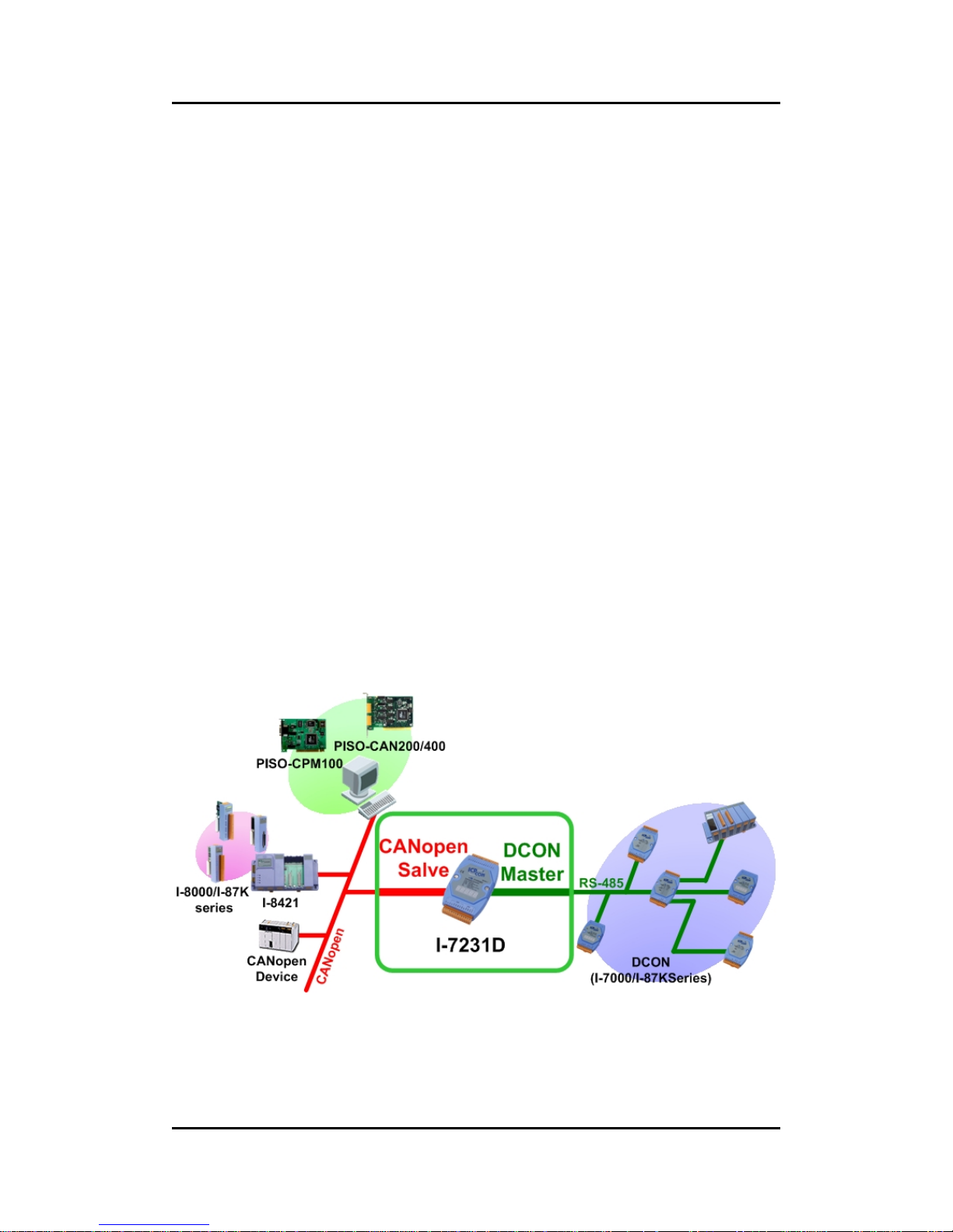
DCON protocol is the default protocol of ICPDAS’s I-7000 and I-87K
modules. The I-7231D is a CANopen slave to DCON master gateway. Using
I-7231D gateway, the DCON I/O modules can be connected with the CAN bus.
In CANopen protocol application, the I-7231D plays the role in a CANopen
slave device. Hence, it can produce or consume the PDO messages, receive
the SDO message from the SDO client, and deal with the NMT messages from
NMT master. In the DCON protocol application, it is a DCON master device.
The I-7231D will collect all I/O information of the I-7000 and I-87K series
modules through the RS-485 port of I-7231D. As long as the I-7231D receiving
the command form CAN bus, it will do the corresponding actions to DCON I/O
channels. In addition, we also provide the utility tool for users to configure the
communication parameters and build EDS file for the I-7231D. Therefore,
users can easily apply I-7k and I-87K IO modules in any CANopen master
interface with EDS file via the I-7231D.
Page 5

I-7231D CANopen/DCON Gateway user manual (ver. 1.04, Dec/14/2010) ------5
1.2 Hardware Features
z CPU:80186, 80MHz
z Philip SJA1000 CAN controller
z Philip 82C250 CAN transceiver
z SRAM:512K bytes
z Flash Memory:512K bytes
z EEPROM:2k bytes
z Real Time Clock
z Built-in Dual-Watchdog
z 16-bit Timer
z 2500 Vrms isolation on CAN side
z Power Supply:3.0W
z Unregulated +10VDC to +30VDC
z Operating Temperature:-25°C to +75°C
z Storage Temperature:-30°C to +85°C
z Humidity:5%~95%
z NS, MS and IO Led directors
COM1
z RS-232: TXD,RXD,RTS,CTS,GND
z Communication speed: 115200 max.
z Configure tool connection
COM2
z RS-485: D2+, D2-
z Communication speed: 115200 max.
z Connect to DCON IO modules
Display
z 7-segmemt LED to show operation mode, Node ID, CAN baud and
RS-485 baud
Page 6

I-7231D CANopen/DCON Gateway user manual (ver. 1.04, Dec/14/2010) ------6
1.3 I-7231D Features
z NMT: Slave
z Error Control: Node Guarding
z Node ID: Setting by Utility
z No. of PDOs: 32 Rx, 32Tx
z PDO Modes: Event-triggered, remotely requested, cyclic and acyclic
SYNC
z PDO Mapping: variable
z No of SDOs: 1 server, 0 client
z Emergency Message: Yes
z CANopen Version: DS-301 v4.01
z Device Profile: DSP-401 v2.0
z Produce EDS file dynamically
z Baud Rate setting by Utility : 10K, 20K, 50K, 125K, 250K, 500K, 800K
and 1M bps
z CAN, ERR and Overrun LED indicators
z Support max 15 I-7000/I-87K I/O series modules
z Auto scan the input channel situations from the DCON modules
z Provide friendly Utility to configure
z Support the watchdog function of I-7000/87K I/O series modules
z 7-segmemt LED to show operation mode, Node ID, CAN baud and
RS-485 baud
Page 7

I-7231D CANopen/DCON Gateway user manual (ver. 1.04, Dec/14/2010) ------7
1.4 Utility Features
z Support CANopen node ID, baud rate setting, and com port
parameters setting
z Support auto scan I-7k/I-87K modules
z Show I-7k/I-87K modules configuration
z Show Application and assembly objects configuration
z Support IO connection path setting
z Support EDS file creating
Page 8
I-7231D CANopen/DCON Gateway user manual (ver. 1.04, Dec/14/2010) ------8
2 Hardware Specification
2.1 Hardware Structure
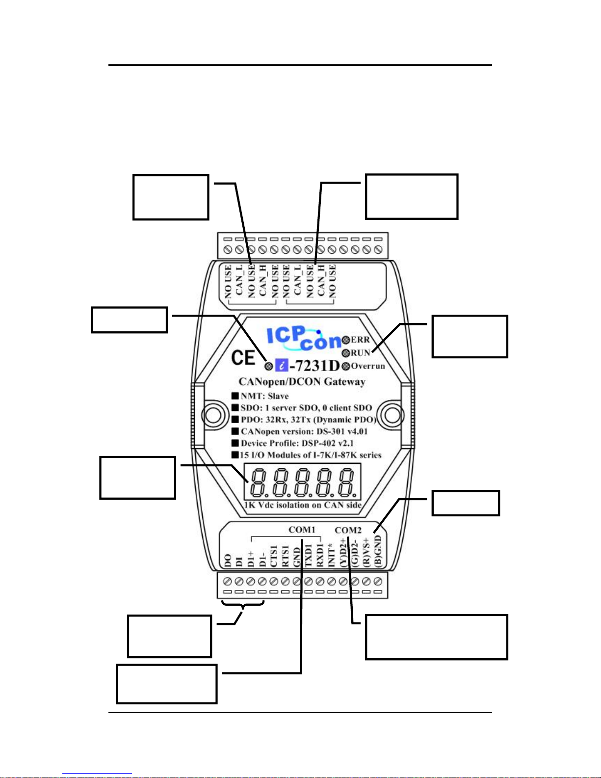
CANopen
Status LED
CAN Bus
Connector
Power LED
7-segment
LED
RS-232 Port
(
connect to PC)
RS-485 Port
(Connect to I/O modules)
Power Pin
Bypass CAN
Bus Connector
Reserved for
time-being
Page 9
I-7231D CANopen/DCON Gateway user manual (ver. 1.04, Dec/14/2010) ------9
2.2 Wire Connection
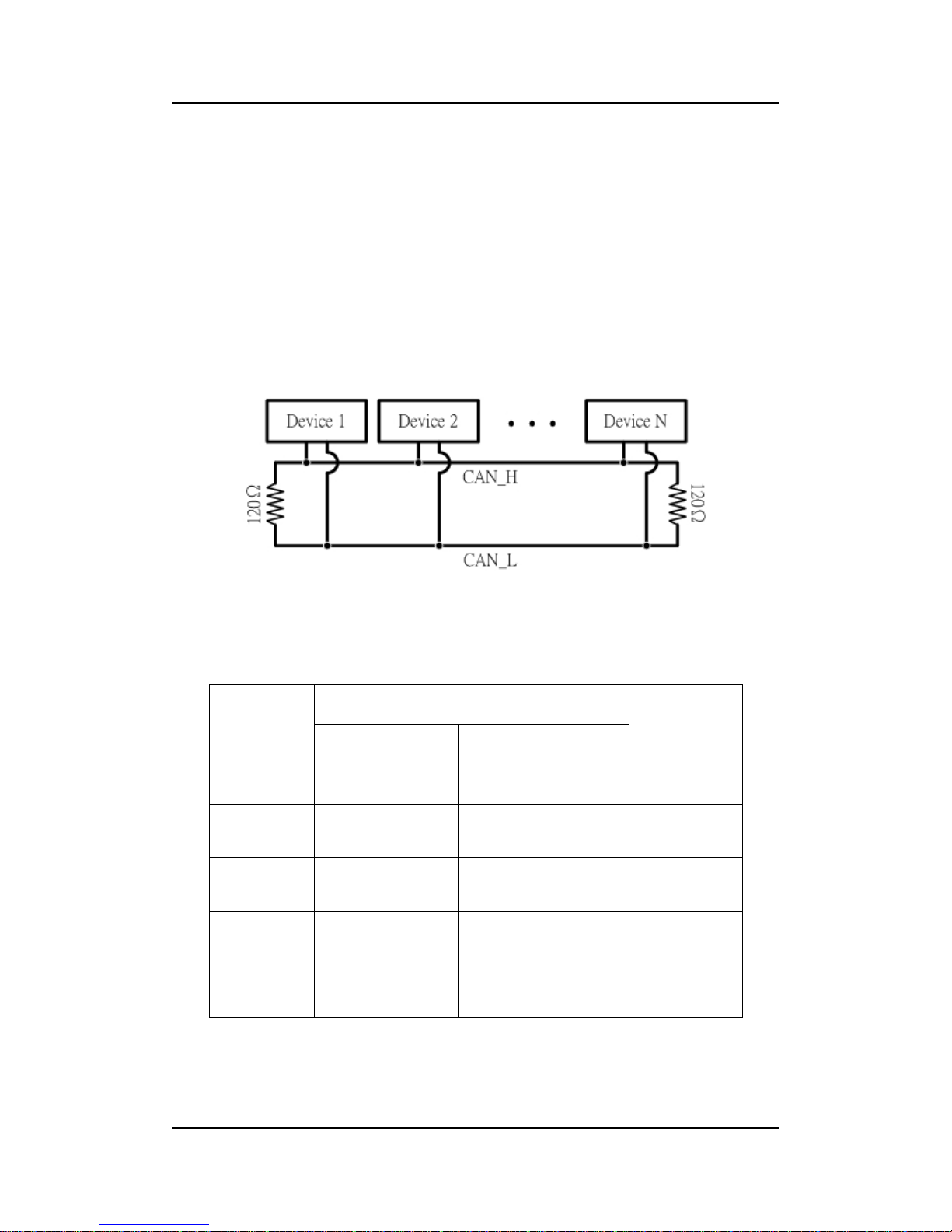
In order to minimize the reflection effects on the CAN bus line, the CAN
bus line has to be terminated at both ends by two terminal resistances as
following figure. According to the ISO 11898-2 spec, each terminal resistance
is 120Ω (or between 108Ω~132Ω). The length related resistance should have
70 mΩ/m. The user should check the resistances of CAN bus, before install a
new CAN network.
Moreover, to minimize the voltage drop on long distance, the terminal
resistance should be higher than the value defined in the ISO 11898-2. The
following table could be a reference.
Bus Cable Parameters
Bus Length
(meter)
Length Related
Resistance
(mΩ/m)
Cross Section
(Type)
Terminal
Resistance
(Ω)
0~40 70 0.25(23AWG)~
0.34mm2(22AWG)
124 (0.1%)
40~300 < 60 0.34(22AWG)~
0.6mm2(20AWG)
127 (0.1%)
300~600 < 40 0.5~0.6mm
2
(20AWG)
150~300
600~1K < 20 0.75~0.mm2
(18AWG)
150~300
Page 10
I-7231D CANopen/DCON Gateway user manual (ver. 1.04, Dec/14/2010) ------10
The CAN bus bard rate has the high relationship with the bus length. The
following table indicates the corresponding bus length on every kind of baud
rate.
Baud rate (bit/s) Max. Bus length (m)
1 M 25
800 K 50
500 K 100
250 K 250
125 K 500
50 K 1000
20 K 2500
10 K 5000
Note: When the bus length is greater than 1000m, the
bridge or repeater devices may be needed.
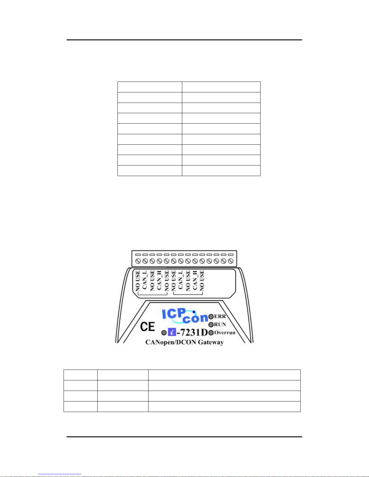
In order to wiring conveniently, the I-7231D supplies two CAN bus
connector. Each connecter built on the CPS_DCON gateway looks like as
following figure.
Pin No. Signal Description
2 CAN_L CAN_L bus line (dominant low)
3 CAN_SHLD Optional CAN Shield
4 CAN_H CAN_H bus line (dominant high)
Page 11
I-7231D CANopen/DCON Gateway user manual (ver. 1.04, Dec/14/2010) ------11
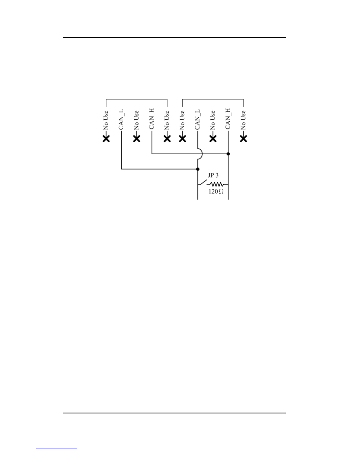
Be careful that the bypass CAN bus connector can’t not be regard as
another CAN channel. It is just designed for connecting to another CANopen
device conveniently. The structure of the internal electronic circuit is presented
as follows.
Page 12

I-7231D CANopen/DCON Gateway user manual (ver. 1.04, Dec/14/2010) ------12
2.3 Power LED
The I-7231D needs 10~30 VDC power input and consumes 3.9W. The
Power LED will be turn on after applying power.
2.4 CANopen Status LED
The I-7231D provides three CANopen LED indicators, such as Error LED
(red), RUN LED (green), and Overrun LED (red). The Error LED and Run LED
are defined in the CANopen spec. When the CANopen communication events
occur, these indicators will be triggered to glitter with different period. The
Overrun LED is defined by ICPDAS. When the software buffer of the I-7231D
is overrun, the overrun LED will turn on. Before the I-7231D finishes the
preparation for the function of the DCON master or when the I-7231D executes
the command to reset itself, all CANopen Status LED will be turned off (but the
Power LED is still turned on). The following descriptions interpret the twinkling
signal meanings when these indicators are triggered.
Page 13
I-7231D CANopen/DCON Gateway user manual (ver. 1.04, Dec/14/2010) ------13
2.4.1 RUN LED
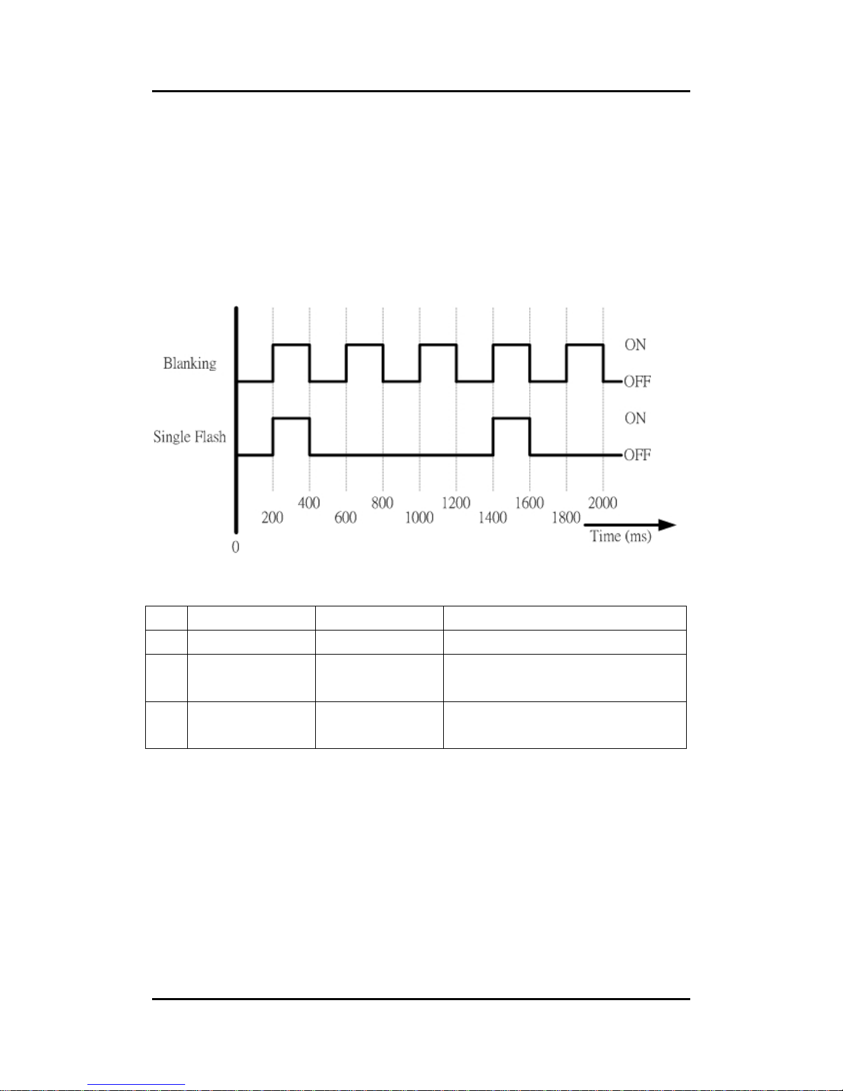
The RUN LED indicates the condition of the CANopen network state
mechanism. About the information of CANopen state mechanism, please refer
to the section 3.5.1. The different signal periods and related meanings are
displayed respectively as following figure and table.
No. CAN RUN LED State Description
1 Single Flash Stopped The Device is in Stopped state
2 Blinking Pre-operational The Device is in the
pre-operational state
3 On Operational The Device is in the operational
state
Page 14
I-7231D CANopen/DCON Gateway user manual (ver. 1.04, Dec/14/2010) ------14
2.4.2 ERR LED
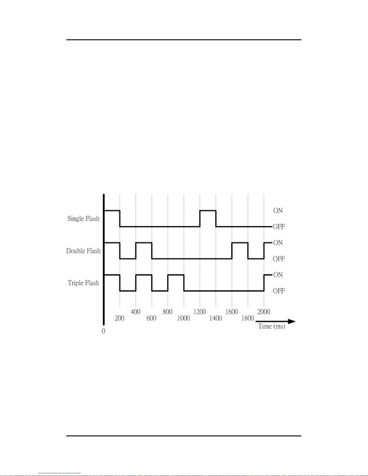
The ERR LED indicates the status of the CAN physical layer and indicates
errors due to missing CAN messages (These messages may be SYNC or
Guard messages). Each error event has different twinkling signal period, and
the signal periods and related meanings are displayed respectively as
following figure and table.
Page 15

I-7231D CANopen/DCON Gateway user manual (ver. 1.04, Dec/14/2010) ------15
No. Error LED State Description
1 Off No error The Device is in working
condition.
2 Single Flash Warning limit
reached
At least one of the error counters
of the CAN controller has
reached or exceeded the warning
level (too many error frames).
3 Double Flash Error Control
Event
A guard event (NMT-Slave or
NMT-master) or a heartbeat
event (Heartbeat consumer) has
occurred.
4 Triple Flash SYNC Error The SYNC message has not
been received within the
configured communication cycle
period time out (see Object
Dictionary Entry 0x1006).
5 On Bus Off The CAN controller is bus off.
Note: If several errors are present at the same duration, the error with the
highest number is indicated. For example, if NMT Error (No. =3) and
Sync Error (No. =4) occur, the SYNC error is indicated.
Page 16

I-7231D CANopen/DCON Gateway user manual (ver. 1.04, Dec/14/2010) ------16
2.4.3 Overrun LED
This LED is useless when the I-7231D works normally. When CAN
message loading is heavy and cause software buffer overrun, the overrun LED
will be turned on. At the same time, an emergency message will be transmitted
to users automatically. In this case, some CAN message may be lost. After the
buffer overrun condition disappears, the LED will be turned off. For further
information of the emergency message, refer to the section 3.4.
Page 17

I-7231D CANopen/DCON Gateway user manual (ver. 1.04, Dec/14/2010) ------17
2.5 7-segment LED
c: Show the operation state of the I-7231D. If it works normally, the LED
displays the character ‘n’.
d: These two LED indicate the CANopen node ID of the I-7231D by using hex
format. For example, if the CANopen node ID of the I-7231D is 31, these
two LED will show the characters “1F”.
e: This LED displays the CAN bus baud rate of the I-7231D by number 0~7.
The meanings of these numbers are described in the table below.
7-segment LED Number Baud rate (K BPS)
0 10
1 20
2 50
3 125
4 250
5 500
6 800
7 1000
c
d
e f
Page 18

I-7231D CANopen/DCON Gateway user manual (ver. 1.04, Dec/14/2010) ------18
f: The RS-485 baud rate of the I-7231D is indicated on this LED. The
mapping table between LED number and RS-485 baud rate is displayed
on the following table.
7-segment LED Number Baud rate (BPS)
0 1200
1 2400
2 4800
3 9600
4 19200
5 38400
6 57600
7 115200
Page 19

I-7231D CANopen/DCON Gateway user manual (ver. 1.04, Dec/14/2010) ------19
2.6 Module Support
The I-7231D supports many kinds of DI, DO, AI and AO modules of
I-7K/I-87K series. When users want to use these modules on the CANopen
network, they only connect these modules with the COM2 of the I-7231D.
Then, the firmware built in the I-7231D will search them for organizing the
corresponding CANopen entries automatically. The following table shows the
modules name and basic information supported by the I-7231D.
Name IO channel Number Name IO channel Number
I-7011
I-7011P
1 DI , 2 DO, 1 AI I-87013 4 AI
I-7012
I-7012F
1 DI , 2 DO, 1 AI I-87016 2 AI
I-7013 1 AI
I-87017
I-87017R
8 AI
I-7014 1 DI , 2 DO , 1 AI
I-87018
I-87018R
8 AI
I-7016 4 DO , 1 DI , 2 AI I-87019 8 AI
I-7016P 4 DO , 1 DI , 1 AI I-87022 2 AO
I-7017
I-7017F
I-7017C
I-7017R
I-7017RC
8 AI I-87024 4 AO
I-7018
I-7018P
I-7018R
I-7018BL
8 AI I-87026 2 AO
I-7019R 8 AI I-87040 32 DI
I-7021 1 AO I-87041 32 DO
I-7022 2 AO I-87051 16 DI
I-7024 4 AO I-87052 8 DI
I-7033 3 AI I-87053 16 DI
I-7041 14 DI I-87054 8 DI , 8 DO
I-7042 13 DO I-87055 8 DI , 8 DO
I-7043 16 DO I-87057 16 DO
Page 20

I-7231D CANopen/DCON Gateway user manual (ver. 1.04, Dec/14/2010) ------20
I-7044 4 DI , 8 DO I-87058 8 DI
I-7045 14 DO I-87063 4 DI , 4 DO
I-7050 7 DI , DO I-87064 8 DO
I-7051 16 DI I-87065 8 DO
I-7052 8 DI I-87066 8 DO
I-7053 16 DI I-87068 8 DO
I-7055 8 DI , 8 DO I-87069 8 DO
I-7058 8 DI
I-7060 4 DI , 4 DO
I-7063
I-7063A
I-7063B
8 DI , 3 DO
I-7065
I-7065A
I-7065B
4 DI , 5 DO
I-7066 7 DO
I-7067 7 DO
I-7080 2 DO,2Count/2Frequency
Page 21
I-7231D CANopen/DCON Gateway user manual (ver. 1.04, Dec/14/2010) ------21
3 CANopen System
3.1 CANopen Introduction
CANopen is a kind of network protocol based on CAN bus and has been
used in various applications, such as vehicles, industrial machines, building
automation, medical devices, maritime applications, restaurant appliances,
laboratory equipment & research. It allows for not only broadcasting but also
peer to peer data exchange between every CANopen node. The network
management functions specified in CANopen simplifies the project design.
Besides, users also can implement and diagnose the CANopen network by
standard mechanisms for network start-up and error management. By the
device model, any CANopen device can effectively access or get the
conditions relating to the I/O values and node states of other devices in the
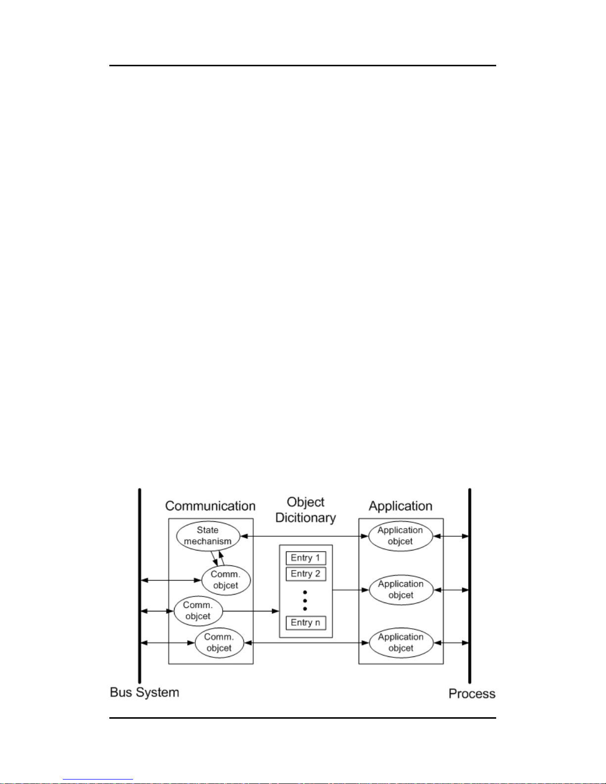
same network. Generally, a CANopen device can be modeled into three parts
z Communication
z Object Dictionary
z Application program
The functions and general concepts for each part are shown as follows.
Page 22
I-7231D CANopen/DCON Gateway user manual (ver. 1.04, Dec/14/2010) ------22
Communication
The communication part provides several communication objects and
appropriate functionalities to transmit CANopen messages via the underlying
network structure. These objects may be PDO (Process Data Object), SDO
(Service Data Object), NMT (Network Management Objects), SYNC
(Synchronous Objects)…etc. Each communication object has its
communication model and functionality. Take the PDO, SDO, and NMT for
examples, the communication objects for accessing the device object
dictionary entries is SDO, and SDO uses the Client/Server structure for its
communication model (section 3.2). The real-time data or I/O value can be
transmitted or received quickly without any protocol overhead by means of
PDO communication objects. The PDOs communication model follows the
Producer/Consumer structure. It is also named the Push/Pull model (section
3.3). NMT communication objects are used for controlling and supervising the
state of the nodes in the CANopen network, and it follows a Master/Slave
structure (section 3.5). No matter which kind of communication object is used,
the transmitted message must obey the data frame defined in the CAN 2.0A
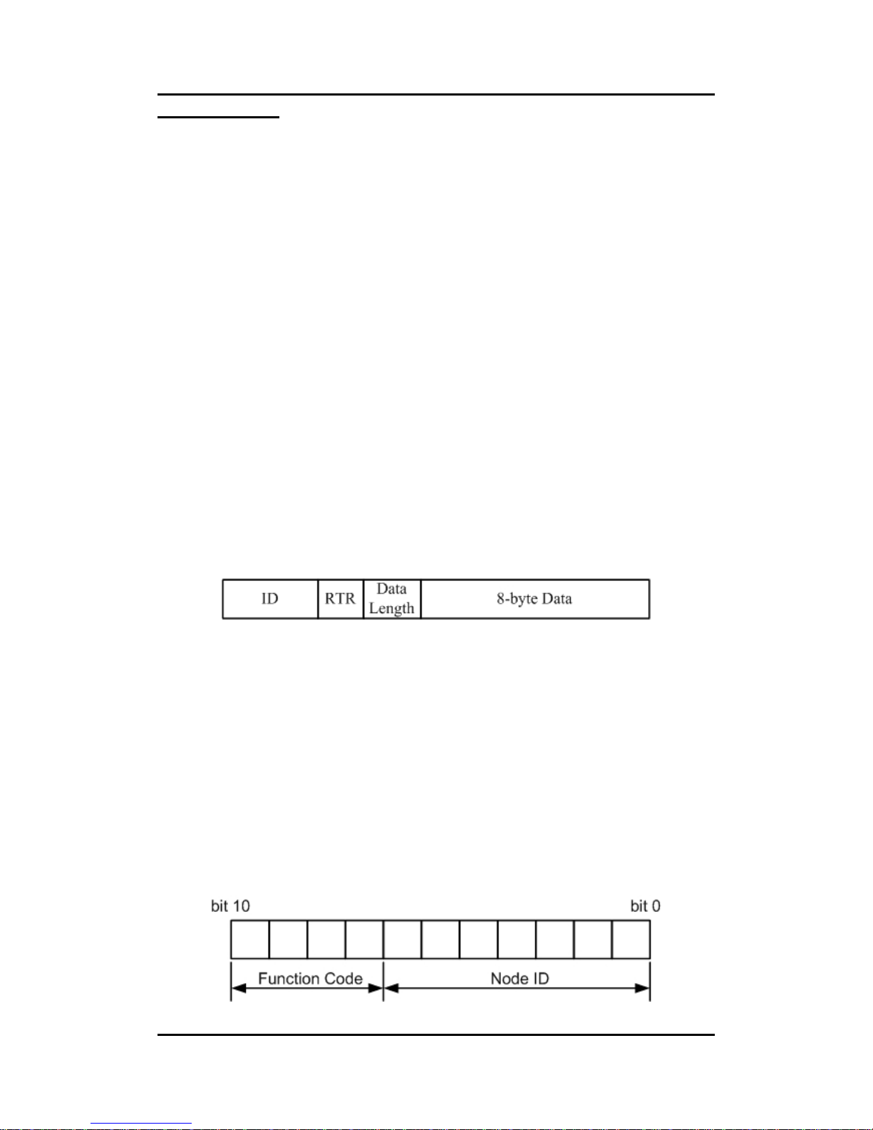
spec. Generally, it looks like the following figure.
The ID field has 11-bit data. It is useful in the arbitration mechanism. The
RTR filed has a one-bit value. If the RTR is set to 1, this message is used for
remote-transmit requests. In this case, the 8-byte data is useless. The data
length field is 4-bit data. It indicates that the valid data number stored in the
8-byte data field. The last field, 8-byte data, is applied to stores the message
data.
CANopen spec uses the 4-bit function code and 7-bit node ID to combine
the 11-bit ID of CAN message, and call it communication object ID (COB-ID).
The COB-ID structure is displayed below.
Page 23

I-7231D CANopen/DCON Gateway user manual (ver. 1.04, Dec/14/2010) ------23
The COB-IDs are defined for recognizing where the message comes from
or where the message must be sent to. Also, they are used to distinguish the
functionality of the transmitted or received messages, and decide the priority of
the message transmission for each node on the network. According to the
arbitration mechanism of the CAN bus, the CAN message with the lower value
COB-ID has the higher priority to be transmitted into the CAN bus. In the
CANopen spec, some COB-IDs are reversed for specific communication
objects and can't be defined arbitrarily by users. The following lists are these
reversed COB-IDs.
Reversed COB-ID (Hex) Used by object
0 NMT
1 Reserved
80 SYNC
81~FF EMERGENCY
100 TIME STAMP
101~180 reversed
581~5FF Default Transmit-SDO
601~67F Default Receive-SDO
6E0 reversed
701~77F NMT Error Control
780~7FF reversed
Page 24

I-7231D CANopen/DCON Gateway user manual (ver. 1.04, Dec/14/2010) ------24
Beside the COB-IDs described above, the other COB-IDs can be applied
by users if need. All of the default COB-IDs used in the CANopen protocol are
shown in the following table.
(Bit10~Bit7)
(Function Code)
(Bit6~Bit0) Communication object Name
0000 0000000 NMT
0001 0000000 SYNC
0010 0000000 TIME STAMP
0001 Node ID EMERGENCY
0011/0101/0111/1001 Node ID TxPDO1/2/3/4
0100/0110/1000/1010 Node ID RxPDO1/2/3/4
1011 Node ID SDO for transmission (TxSDO)
1100 Node ID SDO for reception (RxSDO)
1110 Node ID NMT Error Control
Note: For the I-7231D, we provide all communication objects except for the
TIME STAMP.
Page 25

I-7231D CANopen/DCON Gateway user manual (ver. 1.04, Dec/14/2010) ------25
Object Dictionary
The object dictionary collects a lot of important information. This
information has an influence on the device’s behavior, such as the data in the
I/O channels, the communication parameters and the network states. The
object dictionary is essentially a group of objects. It consists of a lot of object
entries, and these entries can be accessible via the network in a pre-defined
method. Each object entry within the object dictionary has their own
functionality (ex. communication parameters, device profile …), data type (ex.
8-bit Integer, 8-bit unsigned…), and access type (read only, write only …). All
of them are addressed by a 16-bit index and an 8-bit sub-index. The overall
profile of the standard object dictionary is shown below.
Index (hex) Object
0000 Reserved
0001-001F Static Data Types
0020-003F Complex Data Types
0040-005F Manufacturer Specific Data Types
0060-007F Device Profile Specific Static Data Types
0080-009F Device Profile Specific Complex Data Types
00A0-0FFF Reserved for further use
1000-1FFF Communication Profile Area
2000-5FFF Manufacturer Specific Profile Area
6000-9FFF Standardized Device Profile Area
A000-BFFF Standardized Interface Profile Area
C000-FFFF Reserved for further use
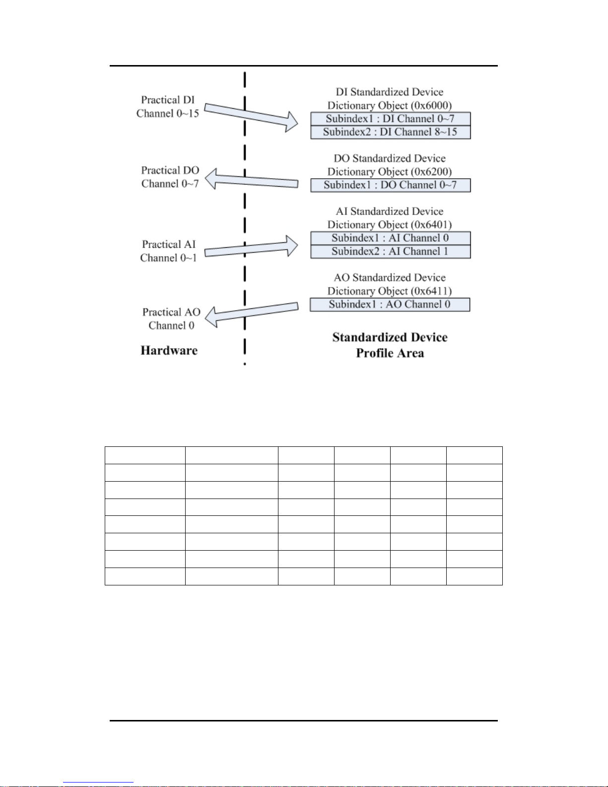
Take the standardized device profile area for an example. Assume that a
CANopen device has 16 DI, 8 DO, 2AI and 1AO channels. The values of these
channels will be stored into several entries in the standardized device
dictionary, such as the entries with indexes 0x6000, 0x6200, 0x6401, and
0x6411. When the CANopen device obtains the input value, these values are
stored in the 0x6000 and 0x6401indexes. Furthermore, the values stored in
the 0x6200 and 0x6411 indexes also output to the DO and AO channels. The
basic concept is depicted as follows.
Page 26
I-7231D CANopen/DCON Gateway user manual (ver. 1.04, Dec/14/2010) ------26
Take the I-7231D as another example. There are some DCON modules
connecting to the COM 2 of the I-7231D. The related information for each
module is shown below.
Module Name Module Address DO (ch) AO (ch) DI (ch) AI (ch)
I-7011 0x 01 2 0 1 1
I-7053 0x 02 0 0 16 0
I-87053 0x 03 0 0 16 0
I-87024 0x 06 0 4 0 0
I-7017 0x 08 0 0 0 8
I-7053 0x 0A 0 0 16 0
I-7041 0x 0B 0 0 14 0
Page 27

I-7231D CANopen/DCON Gateway user manual (ver. 1.04, Dec/14/2010) ------27
When the I-7231D boots up, all the channels of the modules connected
with I-7231D will be scanned. Also, the I/O values of these channels are
arranged into proper object entries one by one. So the minimum data unit is
one byte, the DI and DO channels, which are not enough to fill up one byte, will
be regarded as one byte automatically. The I-7231D uses objects with the
index 0x6000 to store the input values of the DI channels. The I/O values of the
DO, AI, and AO channels are put into the object with the indexes 0x6200,
0x6401, and 0x6411 respectively. When data come through these I/O values
to the corresponding object, it will follow the rules below.
z The modules which are addressed from 0x1 to 0xF, will be taken into
account. The modules with any other addresses will be regarded as
useless.
z The I/O channel values of the DCON modules with lower addresses
are first placed into the object dictionary. After the I-7231D has filled
the all I/O channels in one module, then the I-7231D will go to the
next address to continue.
z Each analog channel is stored by using 2 bytes.
z The number of digital channels for one module, which can’t be
divided by 8 with no remainder, is stored with 1 byte.
Page 28

I-7231D CANopen/DCON Gateway user manual (ver. 1.04, Dec/14/2010) ------28
After using the rule described above, the result of the object filling is as follows.
Index
sub-index
0x6000
(for DI)
0x6200
(for DO)
0x6401
(for AI)
0x6411
(for AO)
0x00 9 1 9 4
0x01 DI0
(MA:0x01)
DO0~DO1
(MA:0x01)
AI0
(MA:0x01)
AO0
(MA:0x06)
0x02 DI0~DI7
(MA:0x02)
AI0
(MA:0x08)
AO1
(MA:0x06)
0x03 DI8~DI15
(MA:0x02)
AI1
(MA:0x08)
AO2
(MA:0x06)
0x04 DI0~DI7
(MA:0x03)
AI2
(MA:0x08)
AO3
(MA:0x06)
0x05 DI8~DI15
(MA:0x03)
AI3
(MA:0x08)
0x06 DI0~DI7
(MA:0x0A)
AI4
(MA:0x08)
0x07 DI8~DI15
(MA:0x0A)
AI5
(MA:0x08)
0x08 DI0~DI7
(MA:0x0B)
AI6
(MA:0x08)
0x09 DI8~DI13
(MA:0x0B)
AI7
(MA:0x08)
Note: MA refers to the “RS-485 module address”
The information described above can also be viewed by using the CAN
Gateway Utility. For more details about the object dictionary and how to use
the CAN Gateway Utility, refer to both chapter 6 and chapter 4.
Application
The application part handles all of the device functionalities which respect
to the interaction with the process environment. It is the bridge between the
object dictionary and practical process, such as the analog I/O, digital I/O….
Page 29
I-7231D CANopen/DCON Gateway user manual (ver. 1.04, Dec/14/2010) ------29
3.2 SDO Introduction
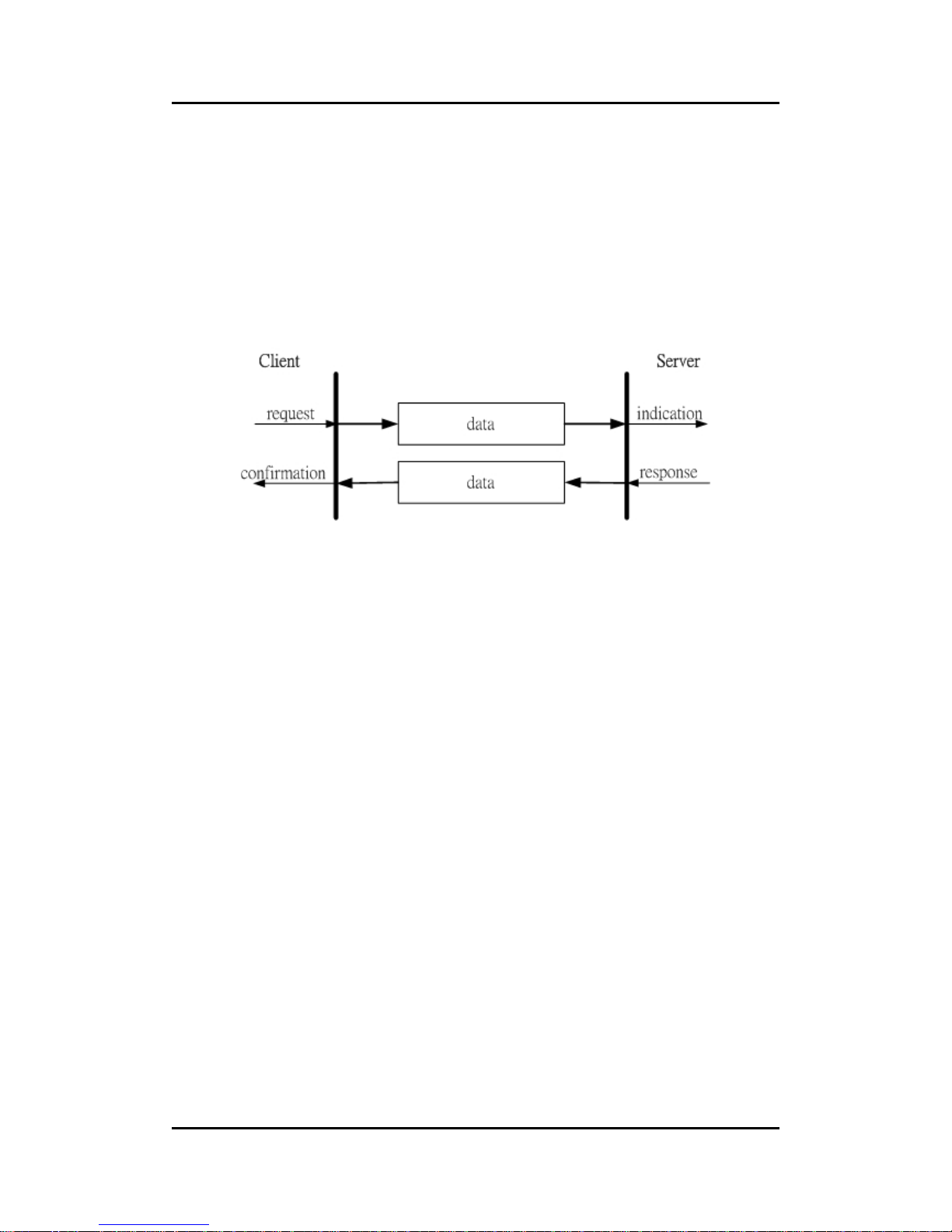
In order to access the entries in a device object dictionary, service data
objects (SDOs) are provided. By means of the SDO communication method, a
peer-to-peer communication bridge between two devices is established. The
SDO transmission follows the client-server relationship. The general concept is
shown in the figure below.
The SDO has two kinds of the COB-IDs, RxSDOs and TxSDOs. They are
viewed at point in the CANopen device. For example, form the view of the
I-7231D, if users want to send a SDO message, then the I-7231D needs to
receive the SDO message transmitted from users. Hence, the receive SDO
(RxSDO) COB-ID of the I-7231D will be used.
If the I-7231D wants to transmit a SDO message, then the TxSDO
COB-ID of the I-7231D will need to be utilized. Before the SDO has been used,
only the client can take the active requirement for a SDO transmission. When
the SDO client starts to transmit a SDO, it is necessary to choose the proper
protocol to transmit the SDO.
If the SDO client has to get the information from the device object
dictionary and from the SDO server, the segment upload protocol or block
upload protocol will be applied. The former protocol is used for transmitting
fewer data; the latter protocol is used for transmitting larger data. Both the
segment download protocol and block download protocol will be implemented
when the SDO client wants to modify the object dictionary to the SDO server.
The differences between the segment download protocol and the block
download protocol are similar to the differences between the segment upload
protocol and the block upload protocol. Because of the different access types
in the object dictionary, not all-accessing action of the object dictionary via the
Page 30
I-7231D CANopen/DCON Gateway user manual (ver. 1.04, Dec/14/2010) ------30
SDO transmission is allowed. If the SDO client trends to modify the entries of
the object dictionary of the SDO server using the read-only access type, then
the abort SDO transfer protocol will be given and the SDO transmission will
also stop.
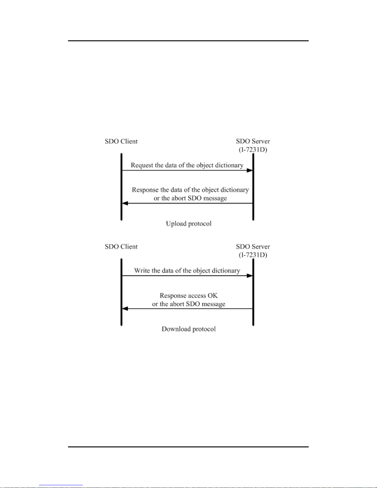
The I-7231D only supports the SDO server. Therefore, it can only be
passive and wait for the client requirements. The general concept of the upload
and download protocol with the I-7231D indicated in the following figure.
Page 31

I-7231D CANopen/DCON Gateway user manual (ver. 1.04, Dec/14/2010) ------31
3.3 PDO Introduction
Communication Modes For The PDO
Based on the transmission data format of the CAN bus, the PDO can
transmit eight bytes of process data at any one time. Because of the PDO
messages without overheads, it is more efficient than other communication
objects within CANopen and is therefore used for real-time data transfer, such
as DI, DO, AI, AO, etc.
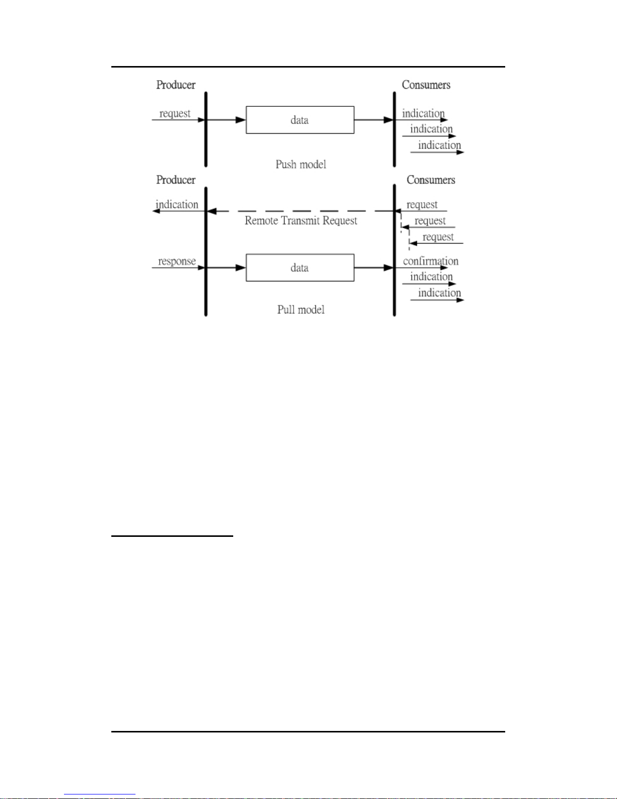
PDO reception or transmission is implemented via the producer/consumer
communication model (also called the push/pull model). When starting to
communicate in the PDO push mode, it needs one CANopen device to play
the role of PDO producer and zero or more than one device to play the role of
PDO consumer.
The PDO producer sends out the PDO message after it has won the CAN
bus arbitration. Afterwards, each PDO consumer receives this PDO message
respectively, and therefore message checks need to be processed or need to
be dropped. In the PDO pull mode, one of the PDO consumers need to send
out a remote transmit request to the PDO producer. According to this remote
request message, the PDO producer responds the corresponding PDO
message for each PDO consumer in the CAN bus. The PDO communication
structure figure is shown below.
Page 32
I-7231D CANopen/DCON Gateway user manual (ver. 1.04, Dec/14/2010) ------32
From the view of the CANopen device, the TxPDO is used to transmit data
from the CANopen device. Therefore, it is usually applied on DI/AI channels.
The COB-ID of the PDO for receiving data is RxPDO COB-ID, and it is usually
applied on DO/AO channels. Take the I-7231D for an example, if a PDO
producer sends a PDO message to the I-7231D, it needs to use the RxPDO
COB-ID of the I-7231D because it is a PDO reception action viewed from the
I-7231D. Inversely, when some PDO consumers send remote transmit
requests to the I-7231D, it must use the TxPDO COB-ID of the I-7231D
because it is a PDO transmission action viewed from the I-7231D.
Trigger Modes Of PDO
For PDO producers, PDO transmission messages can be trigged by three
conditions. They are the event driven, timer driven and remote request
conditions. All of them are described below.
Event Driven
PDO transmission can be triggered by the occurrence of an object specific
event. For PDOs of the cyclic synchronous transmission type, this is the
expiration of the specified transmission period, which is synchronized by the
Page 33

I-7231D CANopen/DCON Gateway user manual (ver. 1.04, Dec/14/2010) ------33
exception of the SYNC message.
For PDOs of the acyclic synchronous or asynchronous transmission type,
the triggering of a PDO transmission is device-specified in the CANopen spec
DSP-401 v2.1. By following this spec, the PDO will be triggered by any change
in the DI-channel states when the transmission type of this PDO is set to
acyclic synchronous or asynchronous.
Timer Driven
PDO transmissions are also triggered by the occurrence of a specific
event for the device or if a specified time has elapsed without the occurrence
of an event. For example, the PDO transmission of the I-7231D can be
triggered by the event timer of the PDO communication parameters, which is
set by the user.
Remote Request
If the PDO transmission type is set to asynchronous or RTR only, the PDO
transmission can only be triggered after receiving a remote transmit request
from any other PDO consumer.
PDO Transmission Types
Generally speaking, there are two kinds of PDO transmission modes,
synchronous and asynchronous. For the PDO in a synchronous mode, it must
be triggered by the reception of a SYNC message. The synchronous mode
can then be distinguished with more detail into three kinds of transmission.
These are the acyclic synchronous, cyclic synchronous and RTR-only
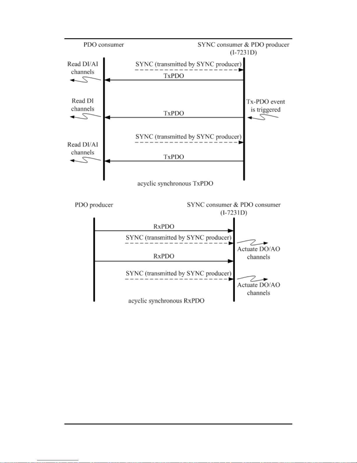
synchronous. The acyclic synchronous can be triggered by both the reception
of a SYNC message and the occurrence of an event defined by an event driver
mentioned above. For the TxPDO object, after receiving a SYNC object from
SYNC producer, the I-7231D will respond with a predefined TxPDO message
to the CANopen PDO consumers. For the RxPDO object, the I-7231D needs
to receive the SYNC object to actuate the RxPDO object, which is received
before the SYNC object. The following figures indicate how the acyclic
synchronous transmission type works on the RxPDO and the TxPDO.
Page 34
I-7231D CANopen/DCON Gateway user manual (ver. 1.04, Dec/14/2010) ------34
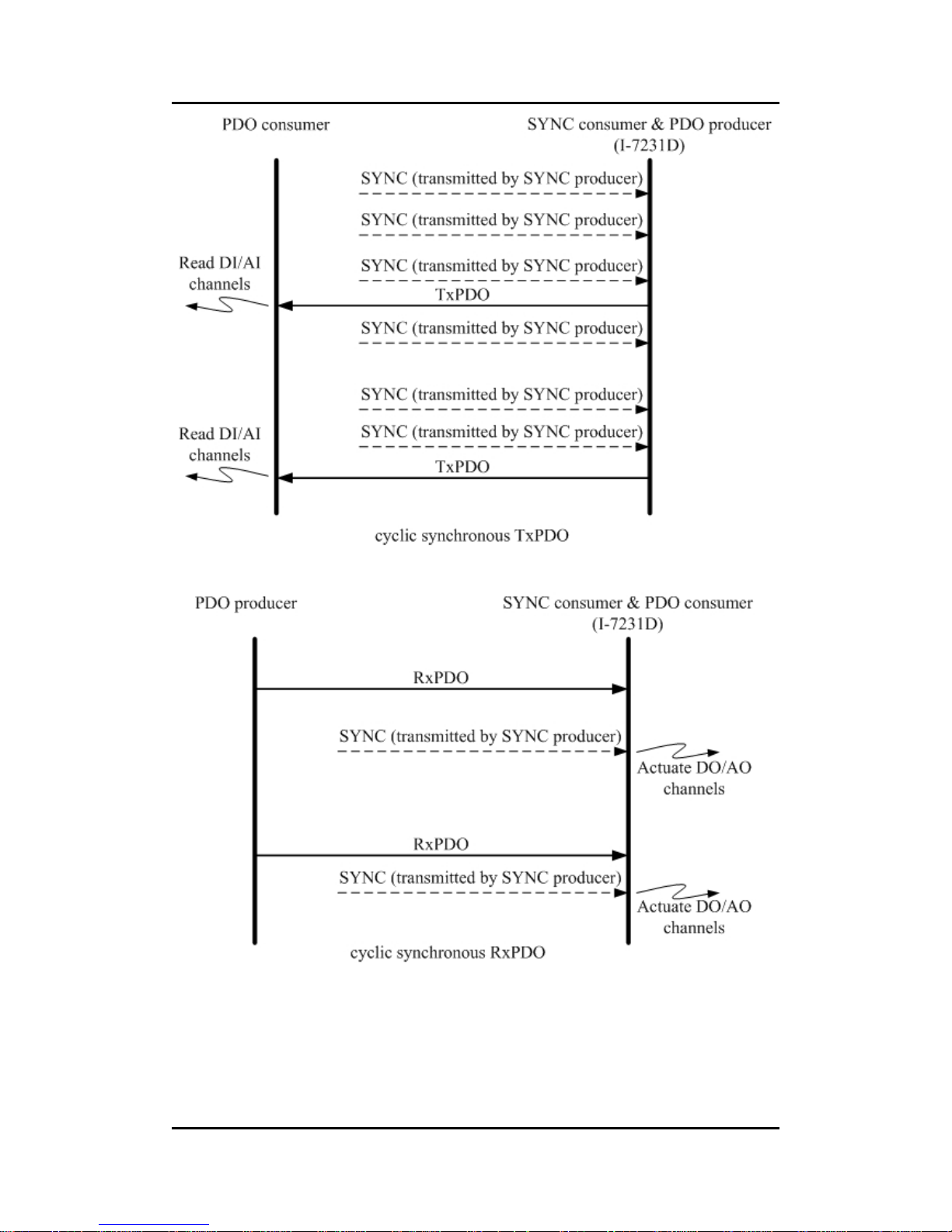
The cyclic synchronous transmission mode is triggered by the reception of
an expected number of SYNC objects, and the max number of expected
SYNC objects can be 240. For example, if the TxPDO is set to react when
receiving 3 SYNC objects, the I-7231D will feedback the TxPDO object after
receiving 3 SYNC object. For the RxPDO, actuating the DO/AO channels by
the RxPDO is independent of the number of SYNC objects. These concepts
are shown in the figures below.
Page 35
I-7231D CANopen/DCON Gateway user manual (ver. 1.04, Dec/14/2010) ------35
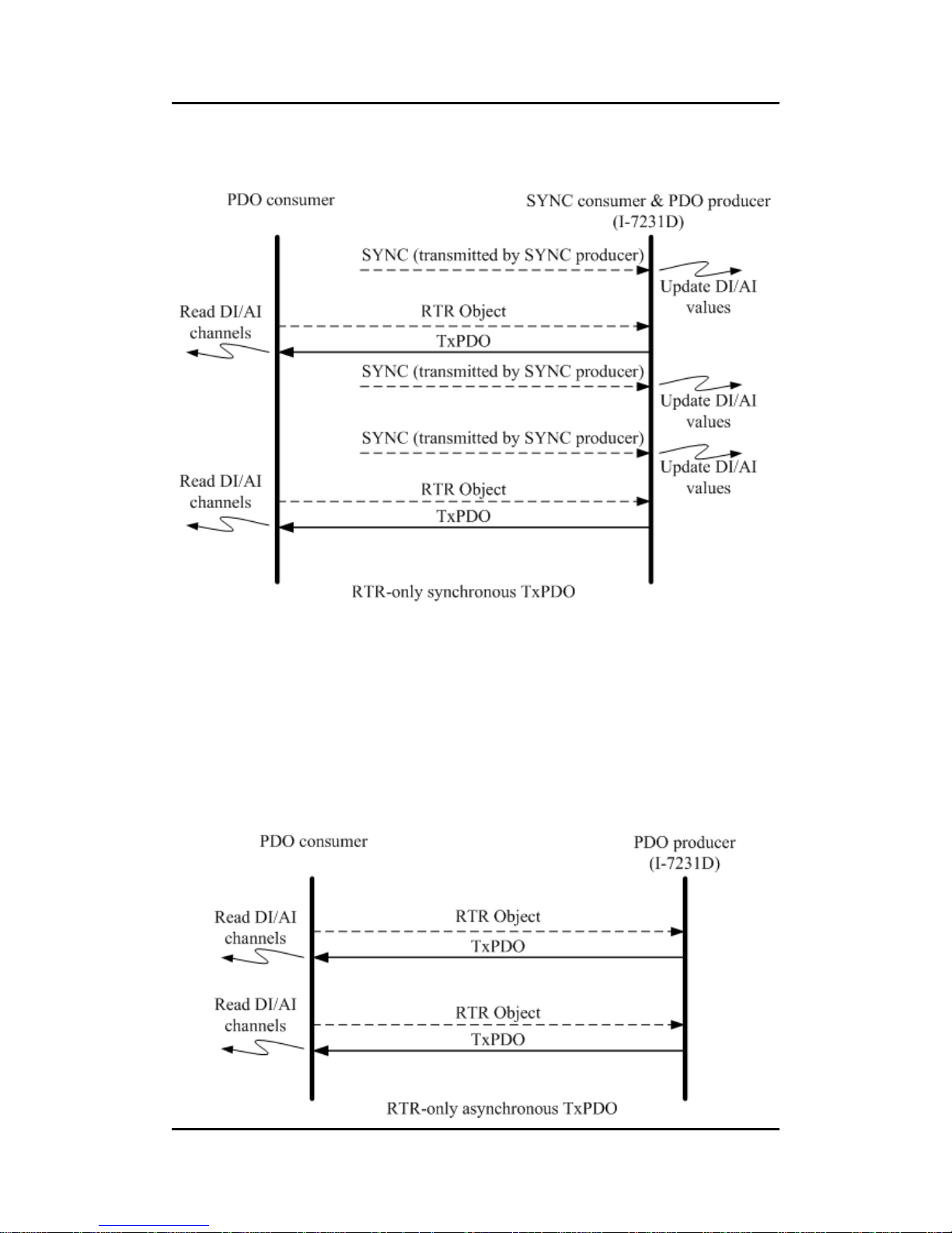
The RTR-only synchronous mode is activated when receiving a
remote-transmit-request message and SYNC objects. This transmission type
is only useful for TxPDO. In this situation, the I-7231D will update the DI/AI
value when receiving the SYNC object. And, if the RTR object is received, the
Page 36
I-7231D CANopen/DCON Gateway user manual (ver. 1.04, Dec/14/2010) ------36
I-7231D will respond to the TxPDO object. The following figure shows the
mechanism of this transmission type.
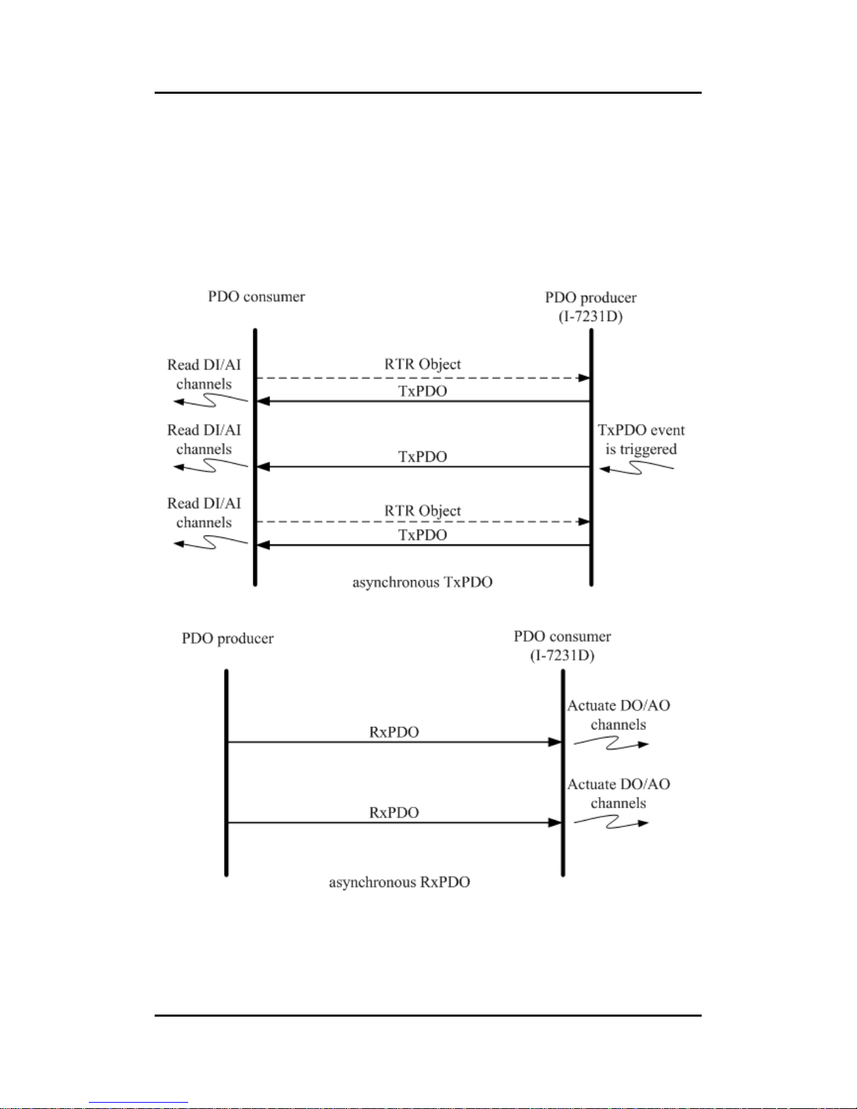
The asynchronous mode is independent on the SYNC object. This mode
can also be divided into two parts for more detail. There are RTR-only
asynchronous transmission type and asynchronous transmission type. The
RTR-only transmission type is only for supporting TxPDO transmissions. For
this transmission type, the TxPDO is only triggered by receiving the RTR
object from the PDO consumer. This action is depicted below.
Page 37
I-7231D CANopen/DCON Gateway user manual (ver. 1.04, Dec/14/2010) ------37
The other part of the asynchronous mode is the asynchronous
transmission type. Under this transmission type, the TxPDO message can be
triggered not only by receiving the RTR object but also by the occurrence of
TxPDO events described in the event driver paragraph described above.
Furthermore, the DO/AO channels can act directly by receiving the RxPDO
object. This transmission type is the default value when the I-7231D boots up.
The concept of the asynchronous type is illustrated as follows.
Page 38

I-7231D CANopen/DCON Gateway user manual (ver. 1.04, Dec/14/2010) ------38
Inhibit Time
Because of the arbitration mechanism of the CAN bus, the smaller
CANopen communication object ID has a higher transmission priority than the
bigger one. For example, there are two nodes on the CAN bus, the one needs
to transmit the CAN message with the COB-ID 0x181, and the other has to
transmit the message with COB-ID 0x182. When these two nodes transmit the
CAN message to the CAN bus simultaneously, only the message containing
COB- ID 0x181 can be sent to the CAN bus successfully because of the higher
transmission priority. The message with COB-ID 0x182 needs to hold the
transmission until the message with COB-ID 0x181 is transmitted successfully.
This arbitration mechanism can guarantee the successful transmission for one
node when a transmission conflict occurs.
However, if the message with COB-ID 0x181 is transmitted again and
again, the message with COB-ID 0x182 will never get a chance to be
transmitted. Therefore, the disadvantage of this arbitration mechanism is that
the lower priority of a CAN message is never transmitted successfully if the
higher priority message is sent continuously. In order to avoid the occupation
of the transmission privilege by the message with a lower COB-ID, the inhibit
time parameters for each of the PDO objects define a minimum time interval
between each PDO message transmission, which has a multiple of 100us.
During this time interval, the PDO message will be inhibited from transmission.
Event Timer
This parameter is only used for TxPDO. If the value of the event timer is
not equal to 0 and the transmission type is in asynchronous mode, the
expiration of this time value is considered to be an event. This event will cause
the transmission of the TxPDO message. The event timer parameter is defined
as a multiple of 1ms.
PDO Mapping Objects
The PDO mapping objects provide the interface between PDO messages
and real I/O data in the CANopen device. They define the meanings for each
byte in the PDO message, and may be changed by using a SDO message. All
of the PDO mapping objects are arranged in the Communication Profile Area.
In the CANopen spec (CiA DS401), RxPDO and TxPDO default mapping
Page 39

I-7231D CANopen/DCON Gateway user manual (ver. 1.04, Dec/14/2010) ------39
objects may be specified as follows:
z There shall be up to 4 enabled TxPDO mapping objects and up to 4
RxPDO mapping objects with default mappings.
z 1st RxPDO and TxPDO mappings are used for digital outputs and
inputs to each other.
z 2nd, 3rd, and 4th RxPDO and TxPDO mapping objects are assigned
to record the value of analog outputs and inputs respectively.
z If a device supports too many digital input or output channels which
exceed the 8 channels, the related analog default PDO mapping
objects shall remain unused and the additional digital I/Os may use
additional PDO mapping objects. This rule shall also be obeyed for
the additional analog channels. Take the RxPDO for example; there
are 11 DO object entries and 13 AI object entries in the object
dictionary. In the default situation for the I-7231D, the first 8 DO object
entries will be mapped to the first RxPDO mapping object because
one DO object entry needs one byte space. The last 3 DO object
entries will be assigned into the 5th RxPDO because of the 2nd and
3rd rule described above. One AO object entry needs 2 bytes of
space. Therefore, the second RxPDO mapping object loads the first 4
AO object entries. The following 4 AO object entries are packed into
the third RxPDO mapping object, and so is the 4th RxPDO mapping
object. Because the 5th RxPDO mapping object has been occupied
by the DO object entries, the last AO object entry shall be assigned
into the 6th RxPDO mapping object.
Before applying the PDO communications, the PDO producer and the
PDO consumers need to have their PDO mapping information for each other.
On the one hand, the PDO producers need PDO mapping information to
decide how to assign the expected practical I/O data into PDO messages. On
the other hand, PDO consumers need the PDO mapping information to know
the meaning of each byte of received PDO message.
That is to say that when a PDO producer transmits a PDO object to PDO
consumers, the consumers contrast this PDO message with PDO mapping
entries which are previously obtained from the PDO producer. Then, interpret
the meanings of these values from the received PDO object. For example, if a
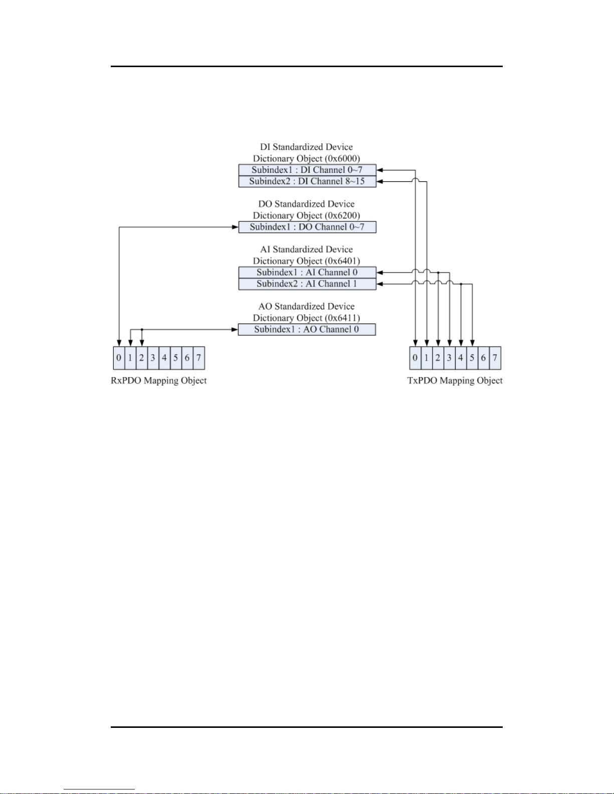
CANopen device has 16 DI, 8 DO, 2 AI, and 1 AO channels. The input or
output values of these channels will be stored into several specific entries for
Page 40
I-7231D CANopen/DCON Gateway user manual (ver. 1.04, Dec/14/2010) ------40
each other. If the user-defined PDO mapping objects have been used, then
general concept for these PDO mapping objects which have been depicted
may be very useful.
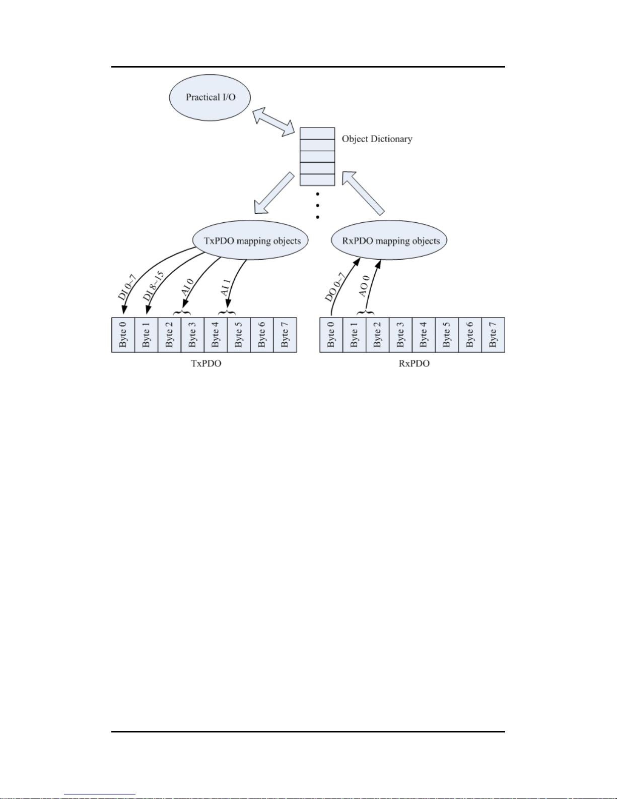
According to the PDO mapping objects in the figure above, if this
CANopen device gets the RxPDO message including three bytes, the first byte
is interpreted as the output value of the DO channels 0~7 and the following two
bytes are the analog output value.
After interpreting the data of the RxPDO message, the device will actuate
the DO and AO channels with the received RxPDO message. This situation is
the same for TxPDO. When the TxPDO trigger events occur, the CANopen
device will send the TxPDO message to the PDO consumers. The values of
the bytes assigned in the TxPDO message follow the TxPDO mapping object
as in the above figure. The first two bytes of the TxPDO message are the
values for the DI channels 0~7 and channel 8~15. The third and forth bytes of
the TxPDO message refer to the AI channel 0 value. The fifth and sixth bytes
are the values link to AI channel 1. The relationships among the object
dictionary, the PDO mapping object and the PDO message are given below.
Page 41
I-7231D CANopen/DCON Gateway user manual (ver. 1.04, Dec/14/2010) ------41
Page 42
I-7231D CANopen/DCON Gateway user manual (ver. 1.04, Dec/14/2010) ------42
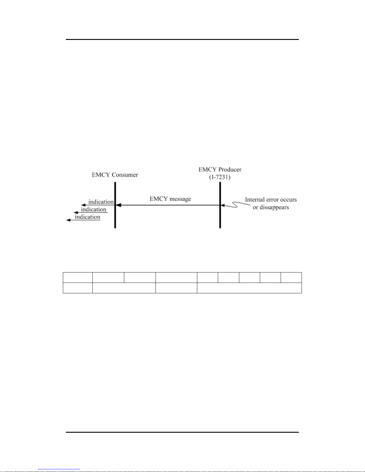
3.4 EMCY Introduction
EMCY messages are triggered by the occurrence of a device internal error.
It follows the producer/consumer relationship. After a CANopen device detects
the internal error, an emergency message is transmitted to the EMCY
consumers only once per error event. No further emergency objects must be
transmitted if no new errors occur on a device. Zero or more emergency
consumers may receive the EMCY object. The I-7231D only supports the
function of the emergency producer. The general concept behind the EMCY
communications is shown below.
An emergency message contains 8-byte of data called emergency object
data, and follows the structure provided bellow.
Byte 0 1 2 3 4 5 6 7
Content Emergency Error Code Error register Manufacturer specific Error Field
All the fields in the emergency object data will be described in section 5.3.
Take the I-7231D for an example, if any errors occur in the I-7231D, the EMCY
message will be sent out from the I-7231D. Afterwards, the EMCY message
will not be transmitted again if the same error occurs repeatedly.
However, if any other different errors detected by the I-7231D occur, it will
trigger the transmission of the EMCY message again. After one but not all error
reasons are gone, an emergency message containing the emergency error
code “00 00” may be responded to with the remaining errors in the error
register and manufacturer specific error fields. Hence, by means of checking
the EMCY message, users can understand what is happening in the I-7231D,
and can then do something about the error event.
Page 43

I-7231D CANopen/DCON Gateway user manual (ver. 1.04, Dec/14/2010) ------43
3.5 NMT Introduction
The Network Management (NMT) follows a node-oriented structure and
also follows the master-server relationship. On the same CAN bus network,
only one CANopen device can have the power to implement the function of
NMT master. All the other CANopen nodes are regarded as NMT slaves. Each
NMT slave is unique, and identified by its node ID from 1 to 127. The NMT
service supplies two protocols, module control protocol and error control
protocol, for different purposes. Through the NMT module control protocol, the
nodes can be controlled into several kinds of status, such as installing,
pre-operational, operational, and stopped. The NMT slave in different statuses
has different privileges to implement the communication protocol. The error
control protocol gives the user the way to detect the remote error in the
network. It can confirm if the node still lives or not.
Page 44
I-7231D CANopen/DCON Gateway user manual (ver. 1.04, Dec/14/2010) ------44
3.5.1 Module Control Protocols
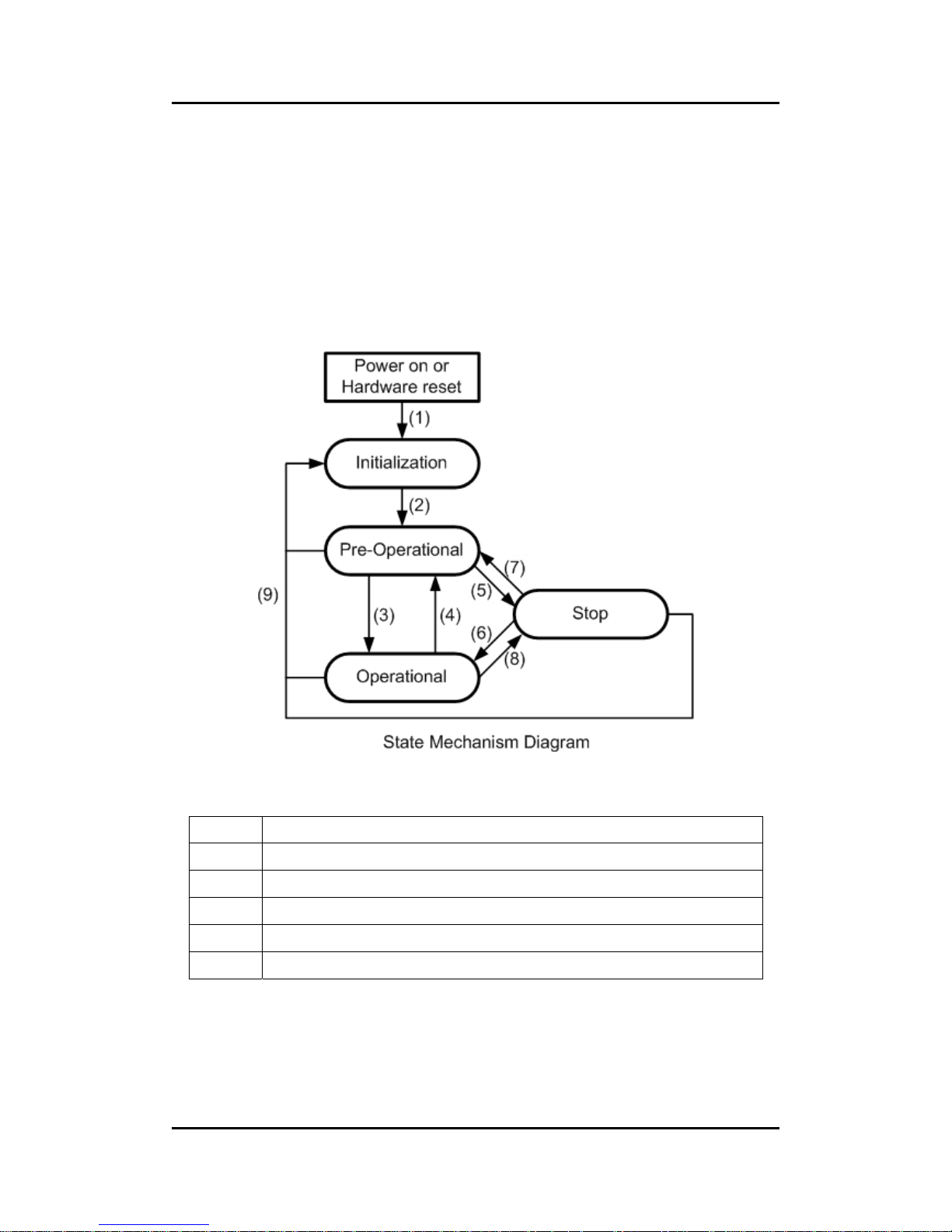
Before introducing the modules control protocols, let’s look at the
architecture of the NMT state mechanism. The following figure displays the
relationships among each NMT state and the mechanism for changing the
NMT state of a NMT slave.
(1) At “Power on” the initialization state is entered autonomously
(2) Initialization finished enter Pre-Operational automatically
(3),(6) “Start Remote Node” indication
(4),(7) “Enter Pre-Optional State” indication
(5),(8) “Stop Remote Node” indication
(9) “Reset Node” or “Reset Communication” indication
Page 45

I-7231D CANopen/DCON Gateway user manual (ver. 1.04, Dec/14/2010) ------45
Devices enter the Pre-Operational state directly after finishing the device
initialization. Then, the nodes can be switched into different states by receiving
an indication. Each different NMT state allows for specific communication
methods. For example, the PDO message can only transmit or receive in the
operational state. In the following table, the relationship among each NMT
state and communication objects is given.
Installing Pre-operational Operational Stopped
PDO
O
SDO
O O
SYNC Object
O O
Time Stamp Object
O O
EMCY Object
O O
Boot-Up Object
O
NMT
O O O
3.5.2 Error Control Protocols
There are two kinds of protocols defined in the I-7231D’s error control
protocol. Note that, according to the CANopen spec, one device is not allowed
to use both error control mechanisms, Guarding Protocol and Heartbeat
Producer Protocol, at the same time. Therefore, users can only use one of
these protocols for the I-7231D in practical application. The node guarding
protocol and the heartbeat protocol of the error protocol is described below.
Page 46
I-7231D CANopen/DCON Gateway user manual (ver. 1.04, Dec/14/2010) ------46
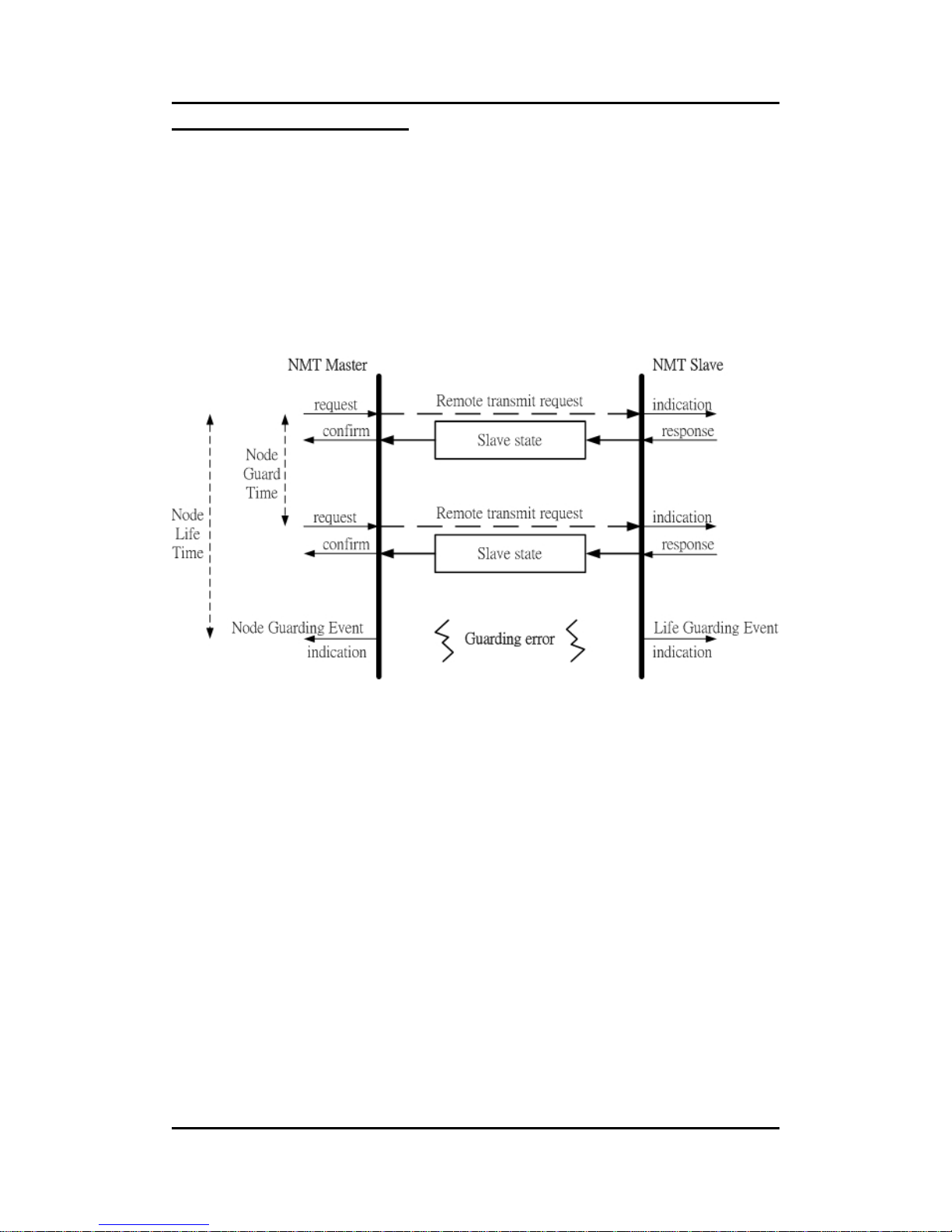
Node Guarding Protocol
The Node Guarding Protocol follows the Master/Slave relationship. It
provides a way to help uses monitor the node in the CAN bus. The
communication method of node guarding protocol is defined as follows.
The NMT master polls each NMT slave at regular time intervals. This
time-interval is called the guard time and may be different for each NMT slave.
The response of the NMT slave contains the state of that NMT slave, which
may be in a "stopped", "operational", or "pre-operational" state. The node life
time is given by the “guard time * life time factor”. The node life time factor can
also be different for each NMT slave. If the NMT slave has not been polled
during its life time, a remote node error is indicated through the "Life Guarding
Event" service.
In addition, the reported NMT slave state, which does not match the
expected state, also produces the “Life Guarding Event”. This event may
occurs in the DO and AO channels to output the error mode value recorded in
the object with index 0x6207 and index 0x6444. The object with index 0x6026
and 0x6443 can control the error mode value of the DO or AO channels to
enable or disable when the “Lift Guarding Event” has been indicated. For more
information about objects with index 0x6206, 0x6207, 0x6443, and 0x6444,
please refer to chapter 6.
Page 47
I-7231D CANopen/DCON Gateway user manual (ver. 1.04, Dec/14/2010) ------47
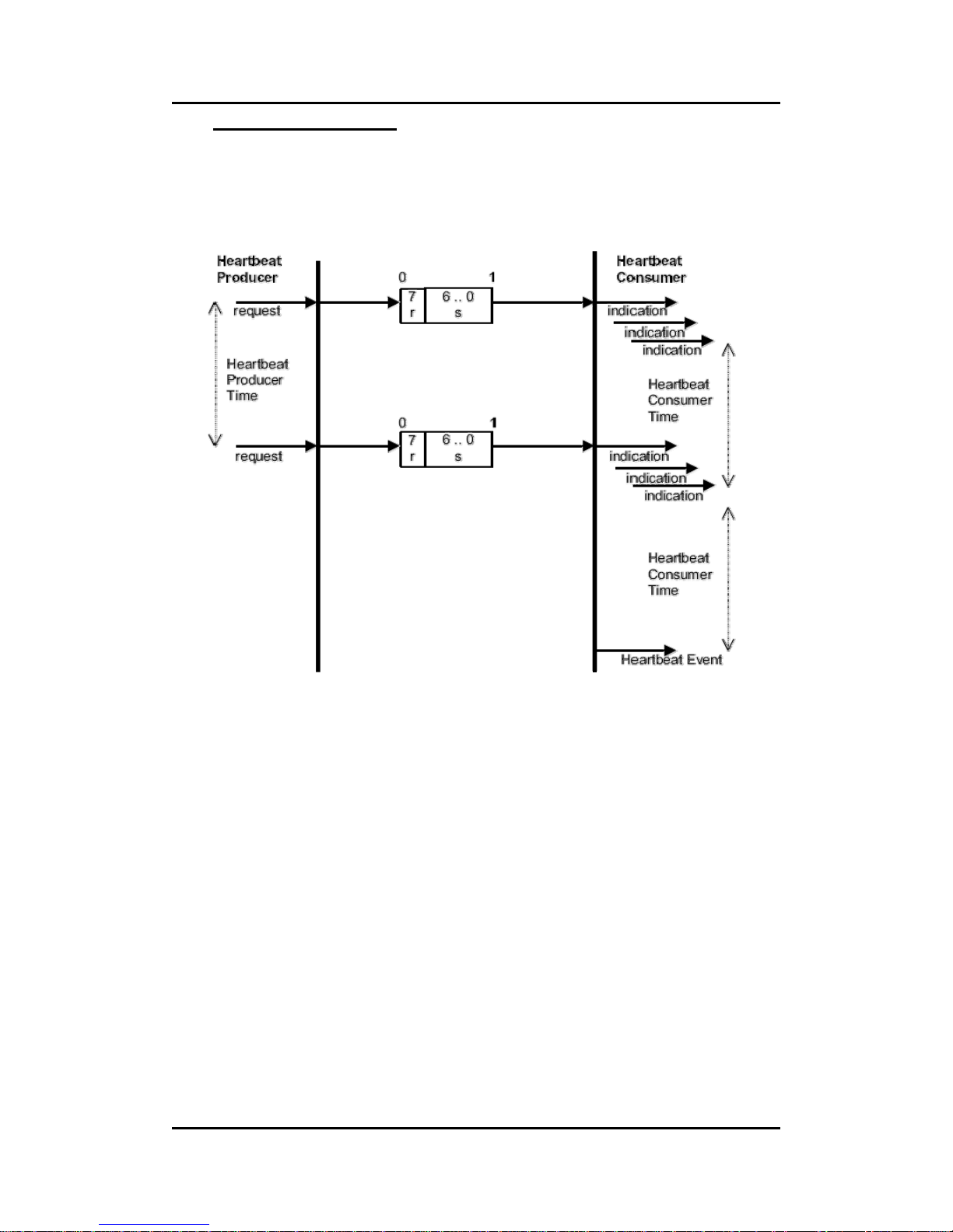
Heartbeat Protocol
The Heartbeat Protocol follows the Producer/Consumer relationship. It
provides a way to help uses monitor the node in the CAN bus. The
communication method of heartbeat protocol is defined as follows.
The Heartbeat Protocol defines an Error Control Service without need for
remote frames. A Heartbeat Producer transmits a Heartbeat message
cyclically. One or more Heartbeat Consumer receive the indication. The
relationship between producer and consumer is configurable via the object
dictionary. The Heartbeat Consumer guards the reception of the Heartbeat
within the Heartbeat Consumer Time. If the Heartbeat is not received within the
Heartbeat Consumer Time a Heartbeat Event will be generated.
Page 48
I-7231D CANopen/DCON Gateway user manual (ver. 1.04, Dec/14/2010) ------48
4 CANopen System
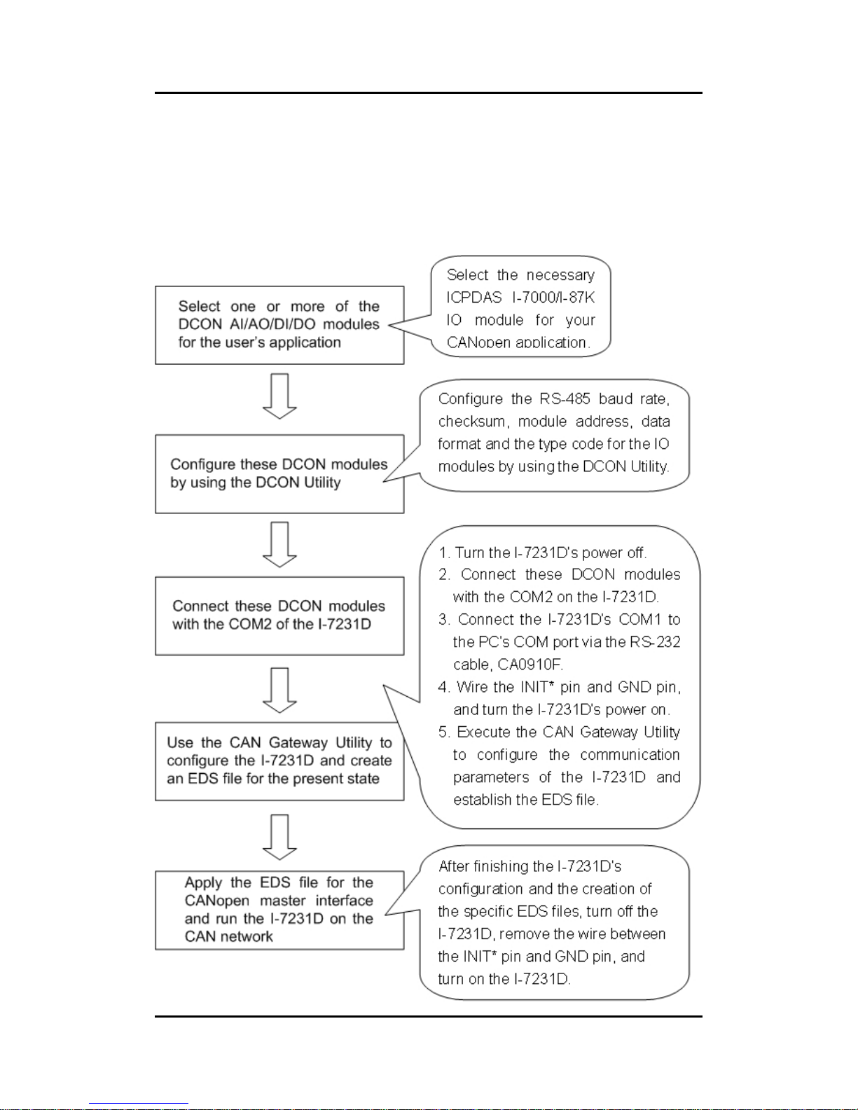
4.1 I-7231D Configuration Flowchart
Page 49

I-7231D CANopen/DCON Gateway user manual (ver. 1.04, Dec/14/2010) ------49
4.2 CAN Gateway Utility Overview
The CAN Gateway Utility is designed for the I-7231D. It provides three
functions.
z Set the communication parameters of the CANopen, CAN bus and
RS-485. Such as Node ID, CAN bus baud rate, RS-485 baud rate,
RS-485 checksum, and RS-485 timeout value.
z Scan the I-7000 or I-87K modules hanging on the COM2 of the
I-7231D. Then, create the EDS file to match the scanning result of
scanning.
z Show the important information which is useful in the CANopen
network and the RS-485 network. Such as the PDO communication
objects, I-7000/I-87K modules information, and the standardized
device objects and manufacturer specific objects defined in the
I-7231D.
Before users start to use the I-7231D, they must configure the
I-7000/I-87K IO modules by using the DCON Utility. During the configuration,
users need to give a unique ID (0x01~0x0F) for each I-7000/87K module in the
RS-485 network. Also, if AI/AO modules are used, users need to choose the
correct type of code for the proper input/output range of these AI and AO
modules. The DCON Utility can be downloaded free from the following web
site.
http://www.icpdas.com/download/7000/7000.htm
For more information about how to configure the I-7000/I-87K modules,
please refer to the on-line help of the DCON Utility or the user manual for the
I-7000/87K modules.
Page 50
I-7231D CANopen/DCON Gateway user manual (ver. 1.04, Dec/14/2010) ------50
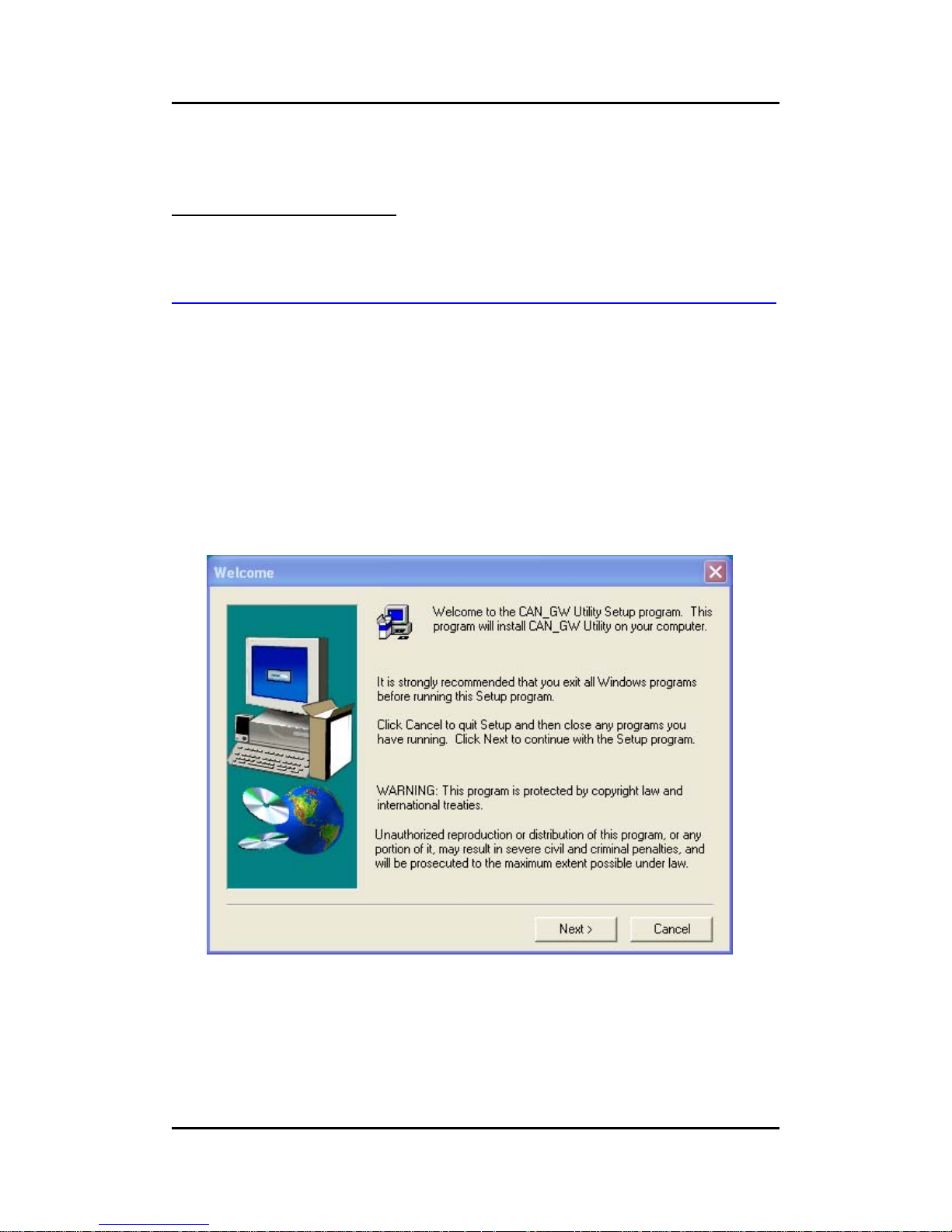
4.3 CAN gateway Utility Installation
Install CAN Gateway Utility
Step 1: Download the CAN Gateway Utility setup file from the web site
http://ftp.icpdas.com/pub/cd/fieldbus_cd/canopen/gateway/i-7231d/utility
or CD-ROM disk following the path of “
/Fieldbus_cd/CANopen/Gateway/I-7231D/Utility.
Step 2: Execute the setup.exe file to install the CAN Gateway Utility.
Step 3: A “Welcome” window pops up to prompt user to begin installation.
Page 51
I-7231D CANopen/DCON Gateway user manual (ver. 1.04, Dec/14/2010) ------51
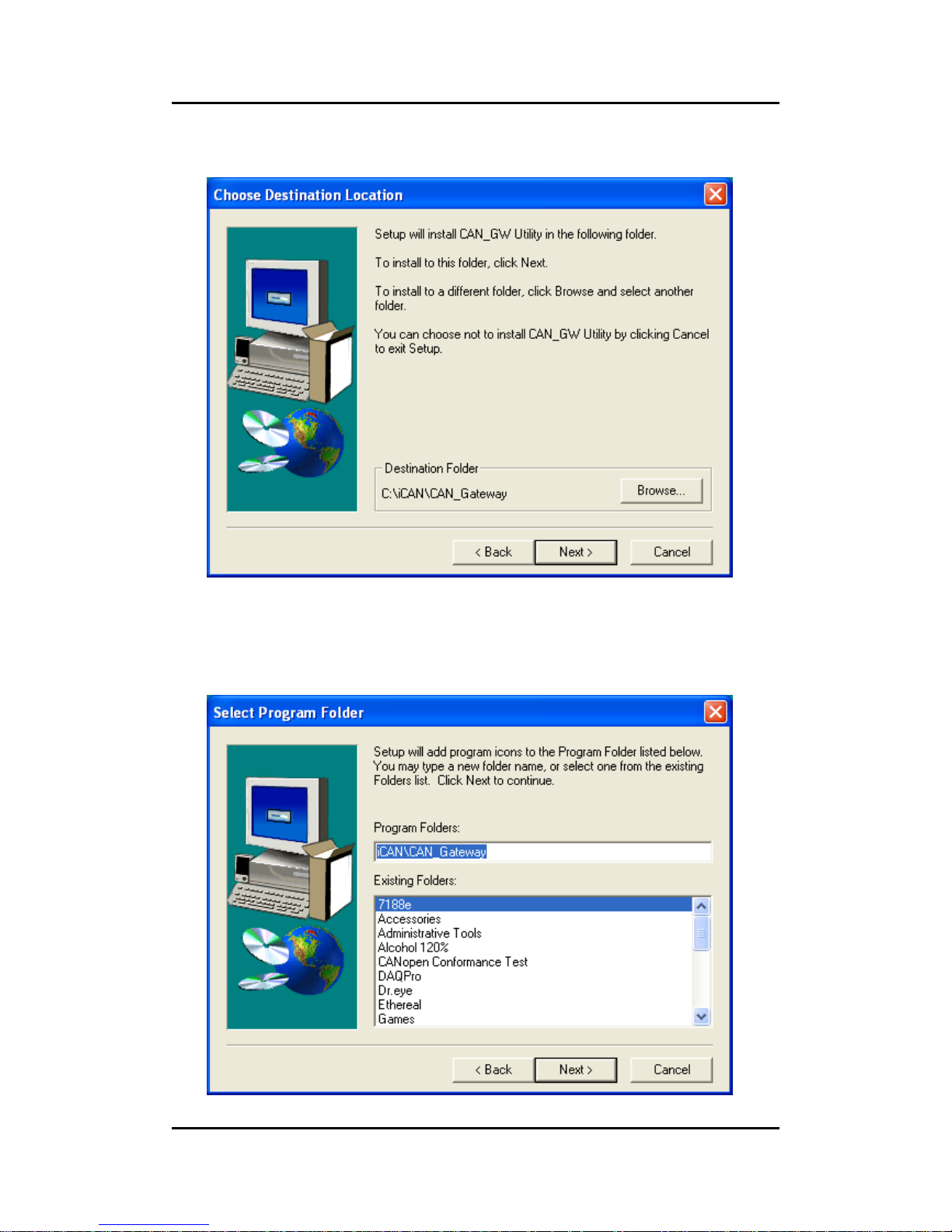
Step 4: Click the “Next” button and a “Choose Destination Location” window
will pop up for deciding the installation path.
Step 5: Click the “Next” button. A “Select Program Folder” window will pop up.
Here, we use the default setting for this field.
Page 52
I-7231D CANopen/DCON Gateway user manual (ver. 1.04, Dec/14/2010) ------52
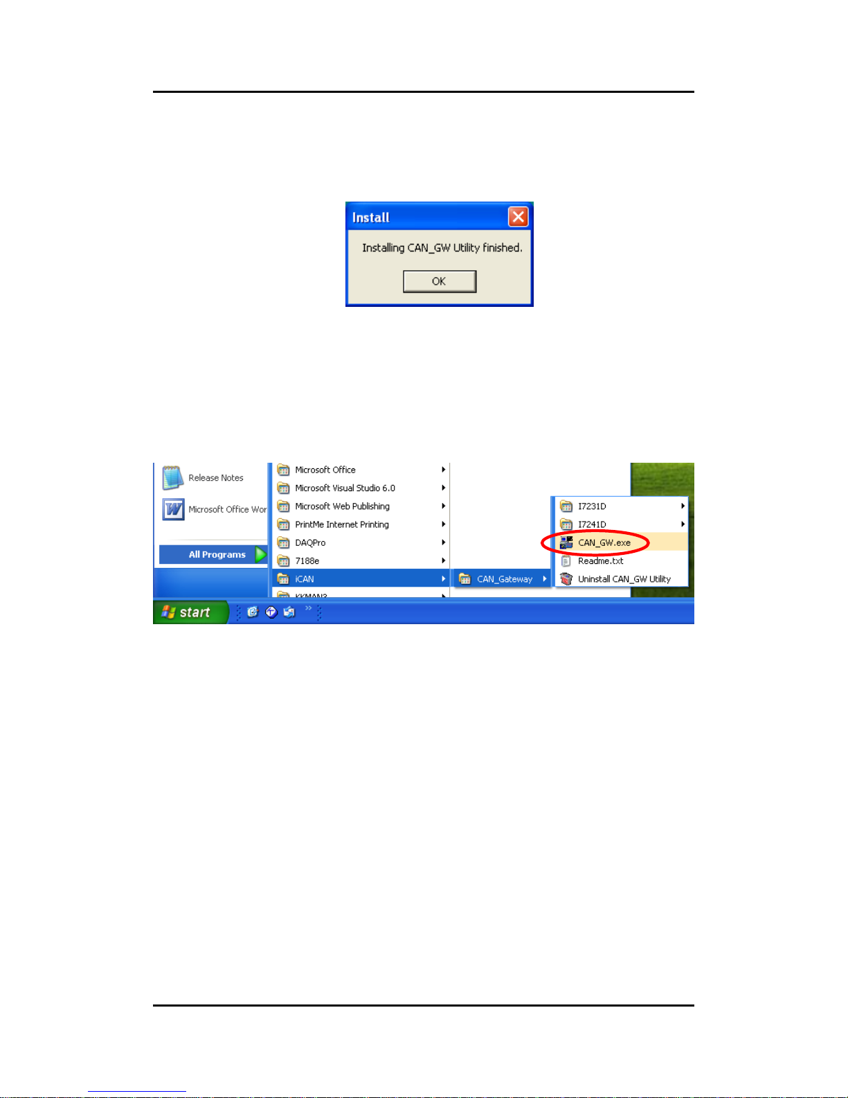
Step 6: Click the “Next” button and start to install the CAN Gateway Utility to
the system. After finishing the process, the following figure will be displayed to
prompts users upon the successful of the installation.
Step 7: After finishing the installation of the CAN Gateway Utility, users can find
the CAN_GW Utility as shown in the following screenshot.
Page 53
I-7231D CANopen/DCON Gateway user manual (ver. 1.04, Dec/14/2010) ------53
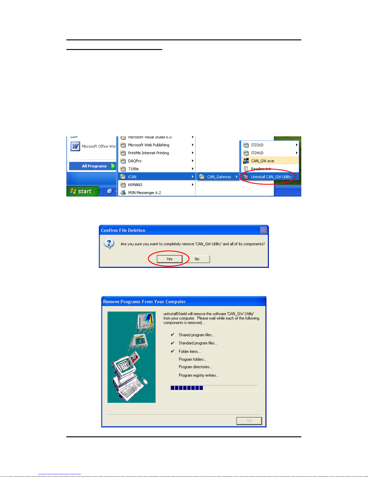
Uninstall CAN Gateway Utility
You can uninstall the CAN_GW Utility software by one means of any on of
the methods described below.
z Method 1
Step 1: Click Start in the task bar. Then, click “Uninstall CAN_GW Utility” to
remove this software.
Step 2: Click the button “Yes” button to remove the software
Step 3: Afterwards, click the button “OK” button to end the uninstall process.
Page 54
I-7231D CANopen/DCON Gateway user manual (ver. 1.04, Dec/14/2010) ------54
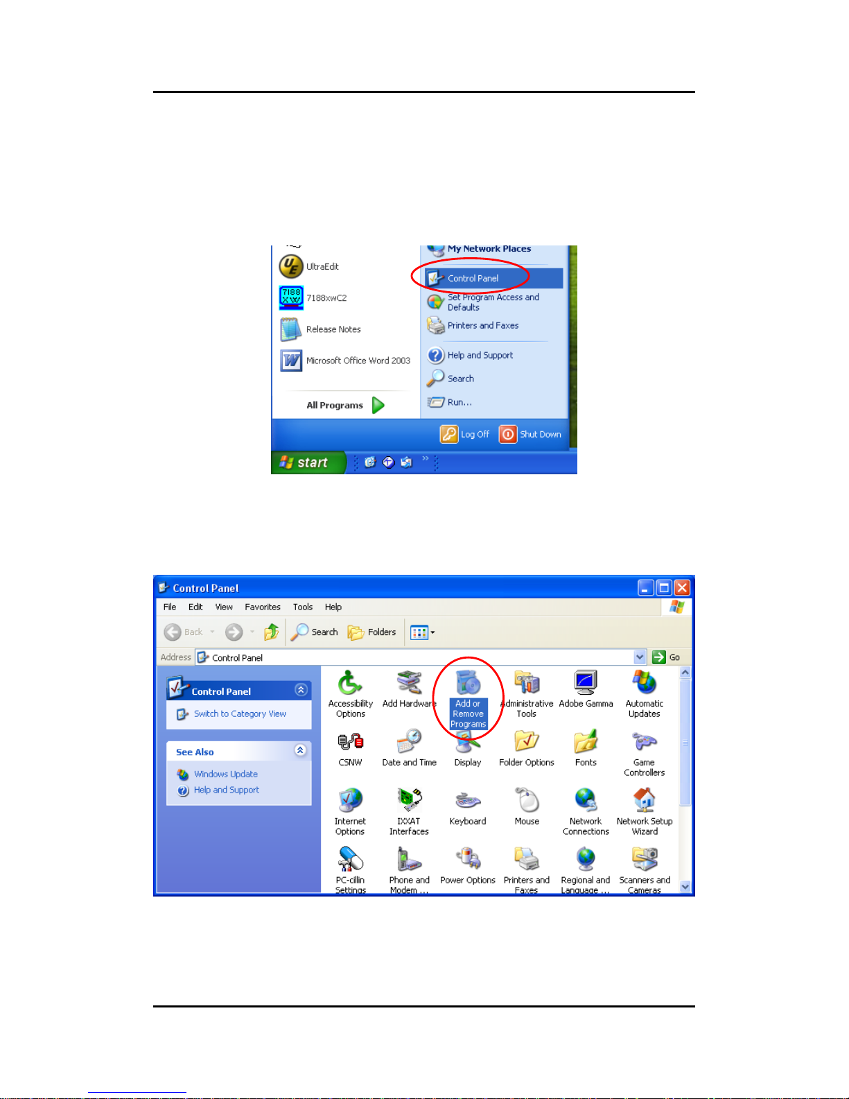
z Method 2
Step 1: Click “Start” in the task bar, then click Setting/Control Panel as shown
in the following figure.
Step 2: Click the “Add/Remove” button Programs icon to open the dialog.
Page 55
I-7231D CANopen/DCON Gateway user manual (ver. 1.04, Dec/14/2010) ------55
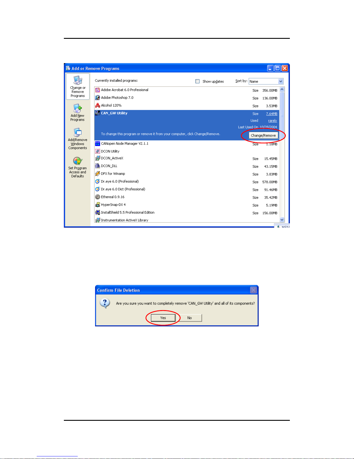
Step 3: Find out the CAN_GW Utility, and click the Change/Remove button.
Step 4: Click the button “Yes” button to remove the software.
Page 56
I-7231D CANopen/DCON Gateway user manual (ver. 1.04, Dec/14/2010) ------56
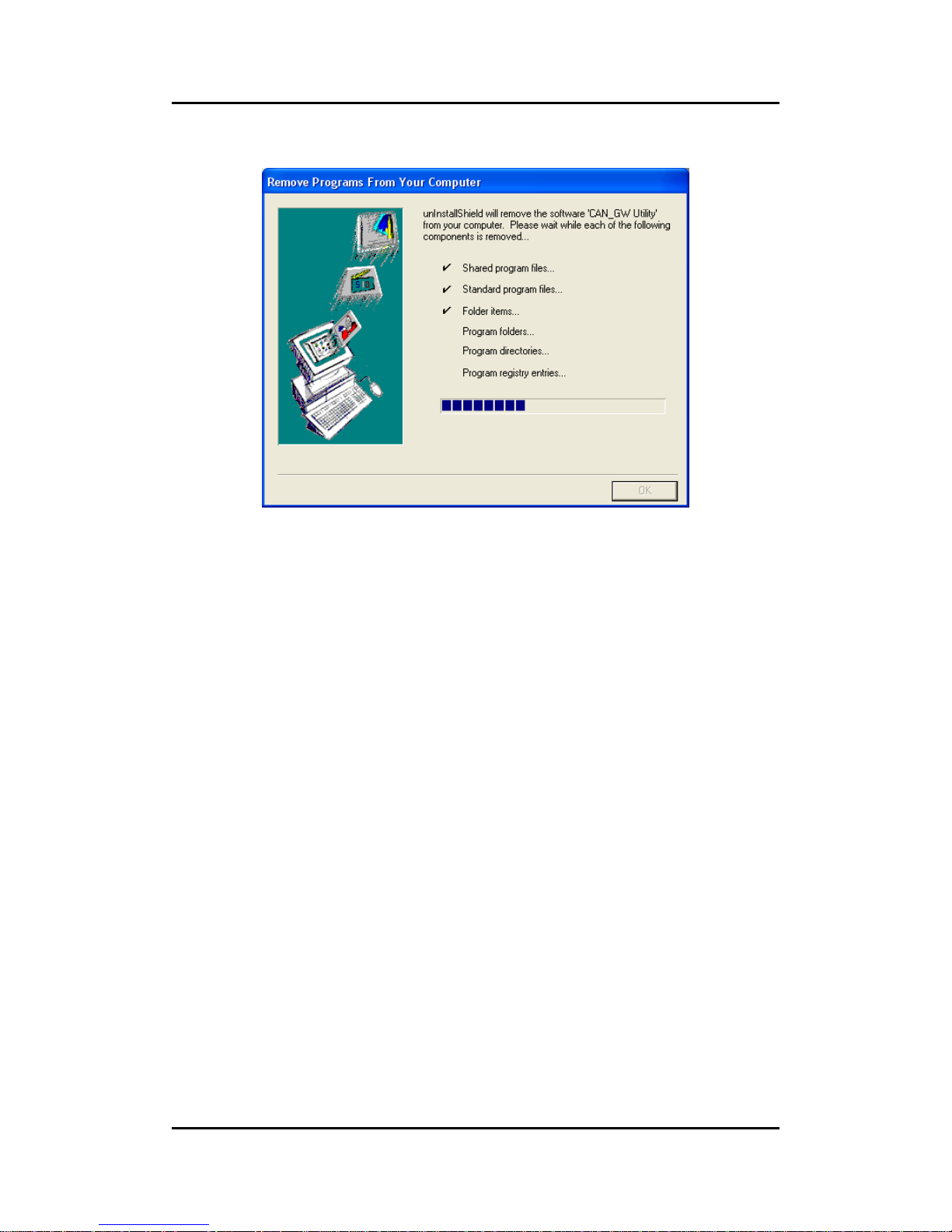
Step 5: Finally, click the button “OK” button to finish the uninstall process.
Page 57
I-7231D CANopen/DCON Gateway user manual (ver. 1.04, Dec/14/2010) ------57
4.4 Configuration with the CAN Gateway Utility
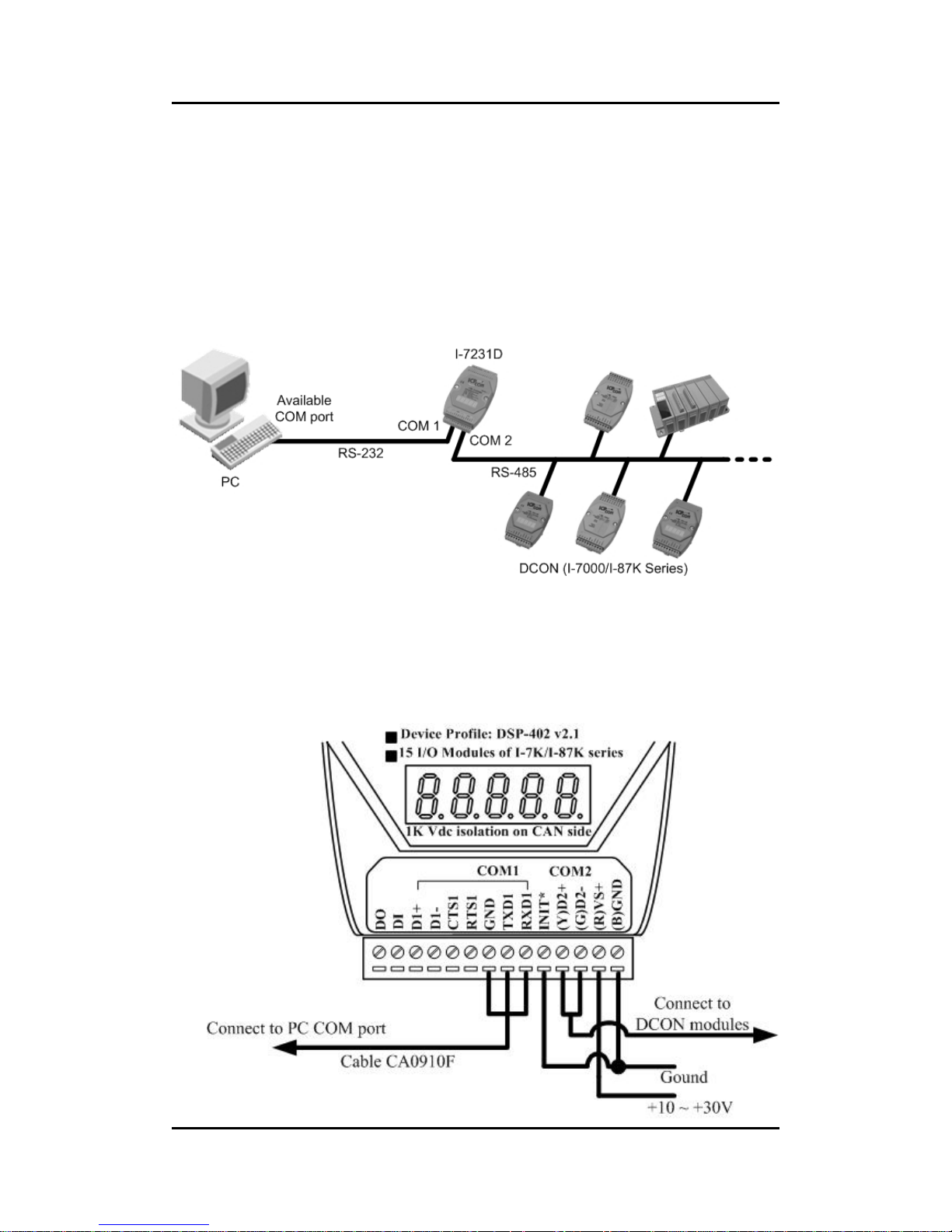
Before using this software utility, please make sure that you have
connected COM1 of the I-7231D with the available COM port on your PC. Also,
connect the I-7000/87K modules with COM2 of the I-7231D. The architecture
is displayed in the following figure.
Step 1: First turn off the I-7231D. Connect the INIT* pin and the GND pin on
the I-7231D. Then, turn on the I-7231D.
Page 58
I-7231D CANopen/DCON Gateway user manual (ver. 1.04, Dec/14/2010) ------58
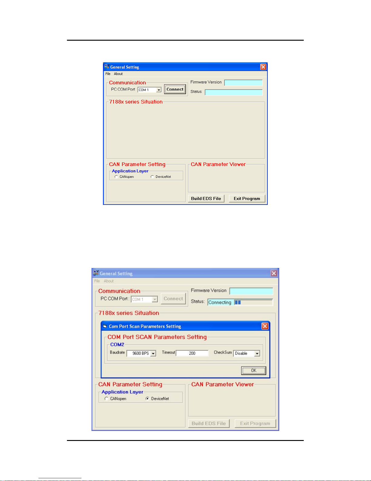
Step 2: Execute the CAN_GW101.exe file. The following software figure will be
displayed.
Step 3: Press the “Connect” button to connect the CANopen gateway. Then
the “Com Port Scan Parameter Setting” dialog window will pop up as follows.
Please set the proper value for the RS-485 communication parameters. These
parameters need to match with the DCON modules parameters. Then, press
the “OK” button to begin the modules scans.
Page 59
I-7231D CANopen/DCON Gateway user manual (ver. 1.04, Dec/14/2010) ------59
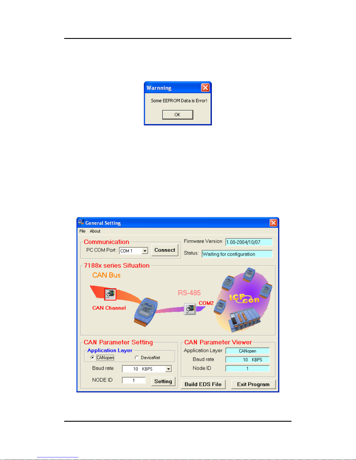
Step 4: When the DCON modules scan is finished, the result of the scan will be
compared with the parameters stored in the EEPROM of the I-7231D. If any
differences have been detected, a warning message will pop up as follows.
The default connected modules are I-7012, I-7021, I-7053 and I-7057.
So if users connect the I-7231D with any different I/O module from the ones
described above, then the “Some EEPROM Data is Error!” warning message
may pop up. In this case, the default value will be shown on each parameter
setting field. Otherwise, the last setting value will be displayed on each
parameter setting field.
Page 60
I-7231D CANopen/DCON Gateway user manual (ver. 1.04, Dec/14/2010) ------60
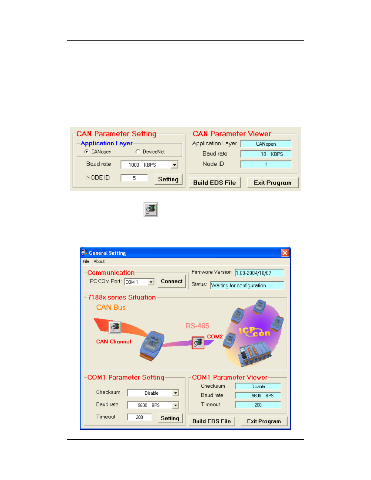
Step 5: Click the “CAN Channel” button so that the CAN bus configuration
information will be given. Then, users can set the necessary CAN bus
communication information. Afterwards, click the “Setting” button to finish the
CAN parameter setting. The CAN Parameter Viewer frame on the right hand
side indicates the parameter setting results. After clicking the “Setting” button,
users can see that each field value on the CAN Parameter Viewer frame has
changed to the value configured in the CAN Parameter Setting frame on the
left hand side.
Step 6: Click the “COM2 ” button to configure the RS-485 parameters for
the CPS_DCON gateway. After finishing the configuration, click the “Setting”
button to save the setting results, and then click the “Build EDS File” button to
continue.
Page 61
I-7231D CANopen/DCON Gateway user manual (ver. 1.04, Dec/14/2010) ------61
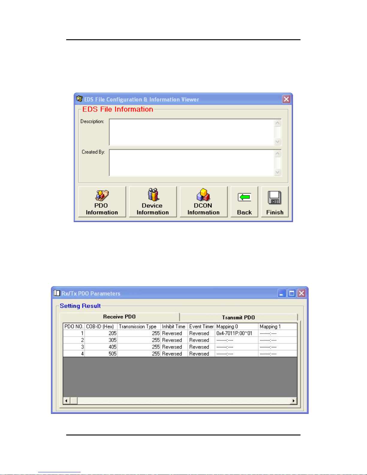
Step 7: The two fields, “description” and “create by”, can help users to do some
notes in the EDS file. If these two fields are empty, the “ICPDAS CANopen
slave/DCON master Gateway” and “ICPDAS” will be used as the default value
when creating the EDS file.
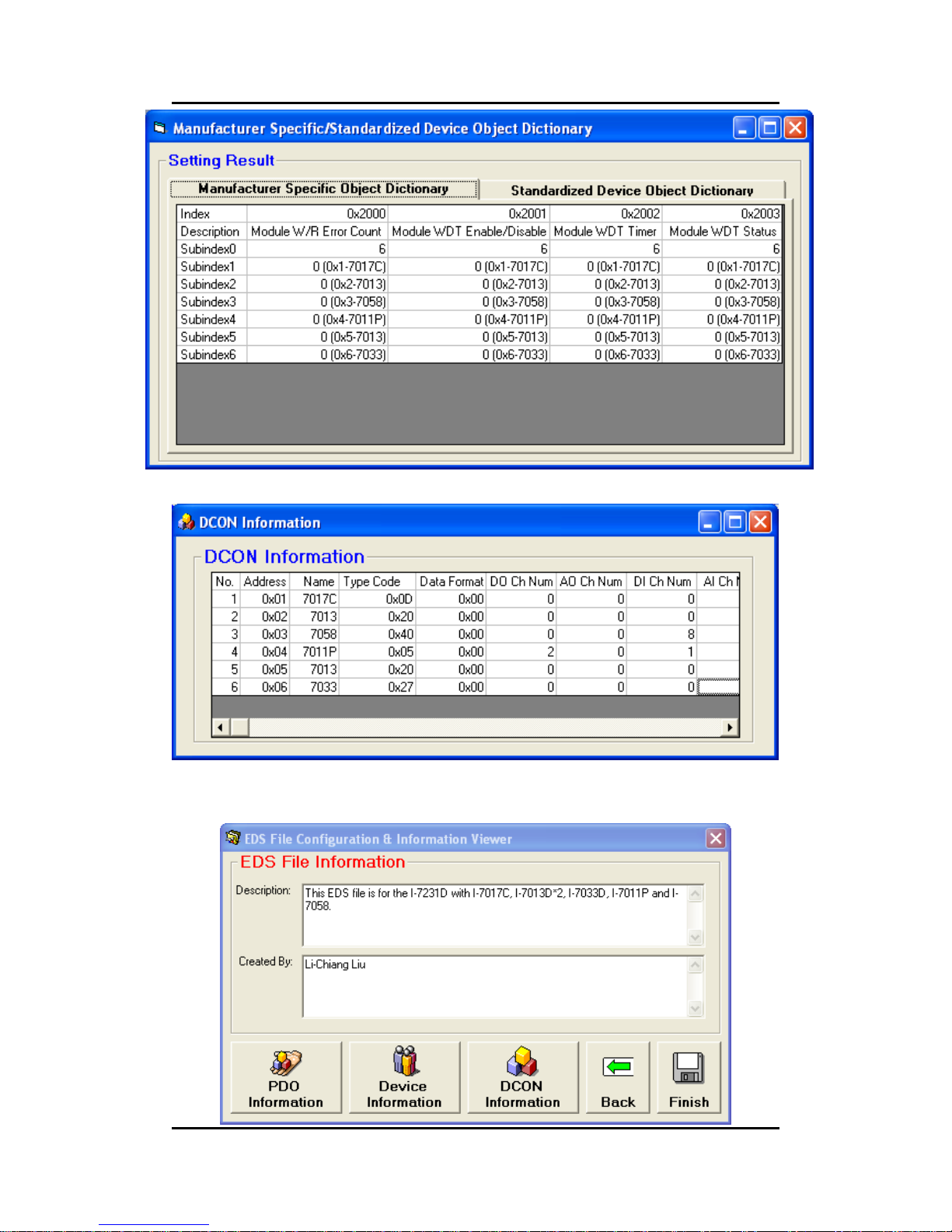
Step 8: Users can click on the “PDO Information”, “Device Information “, and
the “DCON Information button to view the PDO objects, device profile and
I-7000/87K configuration information. These information dialogs are shown
below.
Page 62
I-7231D CANopen/DCON Gateway user manual (ver. 1.04, Dec/14/2010) ------62
If everything is ok, click the “Finish” button to create the EDS file and save the
related information into the EEPROM of the I-7231D.
Page 63
I-7231D CANopen/DCON Gateway user manual (ver. 1.04, Dec/14/2010) ------63
5 Configuration & Getting Start
5.1 SDO Communication Set
5.1.1 Upload SDO Protocol
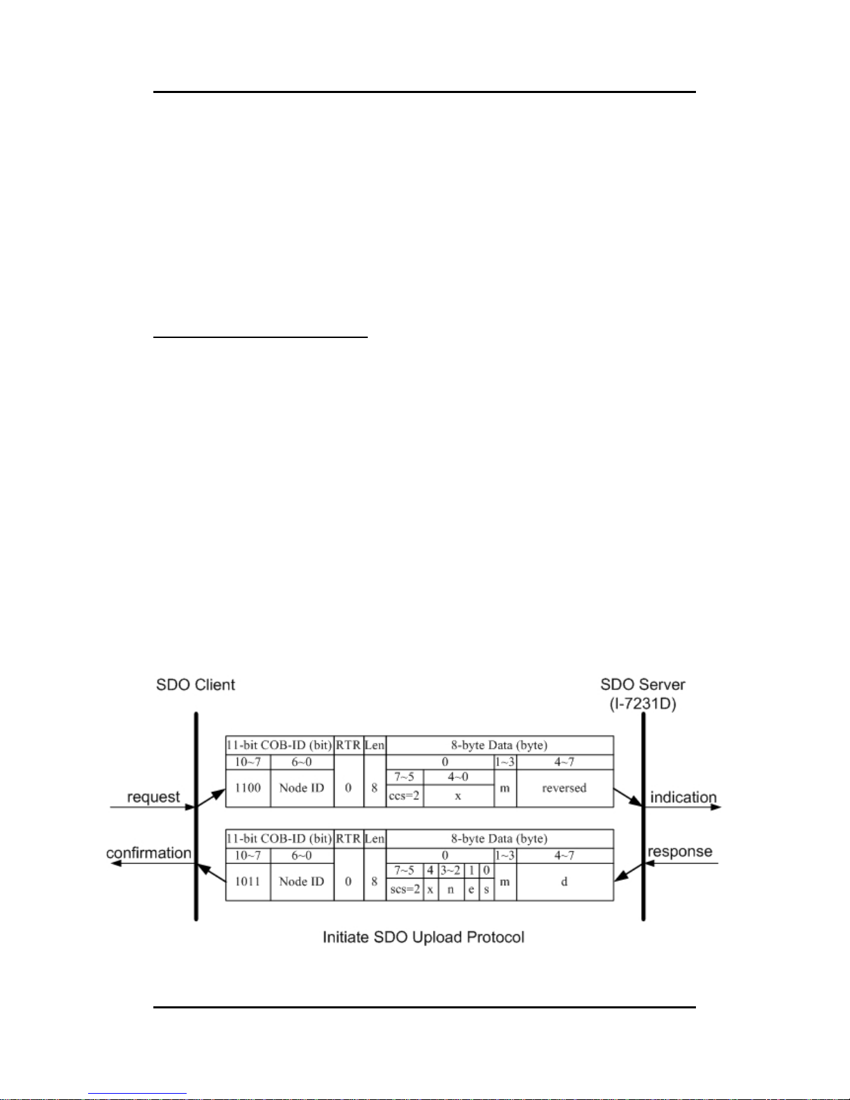
Initiate SDO Upload Protocol
Before transferring the SDO segments, the client and server need to
communicate with each other by using the initiate SDO upload protocol. During
the initiate SDO upload protocol, the SDO client can tell the SDO server what
object the SDO client wants to get. Also, the initiate SDO upload protocol is
permitted to transfer up to four bytes of data. Therefore, if the data length of
the object, which the SDO client wants to read, is equal to or less than the
permitted data amount, the SDO communication can be finished by only using
the initial SDO upload protocol. That is to say, if the data upload is less enough
to be transmitted in the initiate SDO upload protocol, then the upload SDO
segment protocol will not be used. The communication method of this protocol
is shown as follows.
Page 64

I-7231D CANopen/DCON Gateway user manual (ver. 1.04, Dec/14/2010) ------64
ccs
: client command specifier
2: initiate upload request
scs
: server command specifier
2: initiate upload response
n
:
Only valid if e = 1 and s = 1, otherwise 0. If valid, it indicates the
number of bytes in d that do not contain data. Bytes [8-n, 7] do
not contain segment data.
e
: transfer type
0: normal transfer
1: expedited transfer
If the e=1, it means that the data of the object are equal or less
than 4 bytes, and only initiate SDO upload protocol is needed. If
e=0, the upload SDO protocol is necessary.
s
: size indicator
0: Data set size is not indicated.
1: Data set size is indicated.
m
: multiplexer
It represents the index/sub-index of the data to be transfer by the
SDO. The first two bytes are the index value and the last byte is
the sub-index value.
d
: data
e=0, s=0: d is reserved for further use.
e=0, s=1: d contains the number of bytes to be uploaded, and
byte 4 contains the least significant bit, and byte 7
contains the most significant bit.
e=1, s=1: d contains the data of length 4-n to be uploaded, the
encoding depends on the type of the data referenced
by index and sub-index.
e=1, s=0: d contains unspecified number of bytes to be
uploaded.
x
: not used, always 0
reserved
: reserved for further use , always 0
Page 65
I-7231D CANopen/DCON Gateway user manual (ver. 1.04, Dec/14/2010) ------65
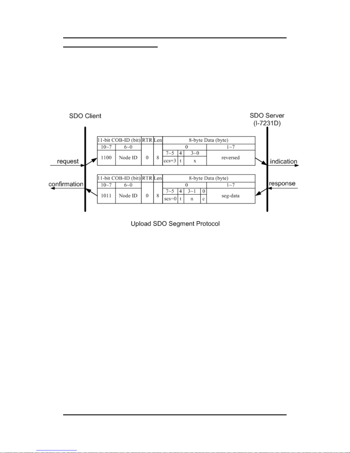
Upload SDO Segment Protocol
When the upload data length exceeds 4 bytes, the upload SDO segment
protocol is needed. After finishing the transmission of the initiate SDO upload
protocol, the SDO client starts to upload the data, and the upload segment
protocol will follow the process shown below.
Page 66

I-7231D CANopen/DCON Gateway user manual (ver. 1.04, Dec/14/2010) ------66
ccs
: client command specifier
3: upload segment request
scs
: server command specifier
0: upload segment response
t
: toggle bit
This bit must alternate for each subsequent segment that is
uploaded. The first segment will have the toggle bit set to 0. The
toggle bit will be equal for the request and the response
message.
c
: indicates whether there are still more segments to be uploaded
0: more segments to be uploaded.
1: no more segments to be uploaded.
seg-data
: It is at most 7 bytes of segment data to be uploaded. The
encoding depends on the type of the data referenced by index
and sub-index.
n
:
It indicates the number of bytes in seg-data that do not contain
segment data. Bytes [8-n, 7] do not contain segment data. n = 0
if no segment size is indicated.
x
: not used, always 0
reserved
: reserved for further use , always 0
Page 67
I-7231D CANopen/DCON Gateway user manual (ver. 1.04, Dec/14/2010) ------67
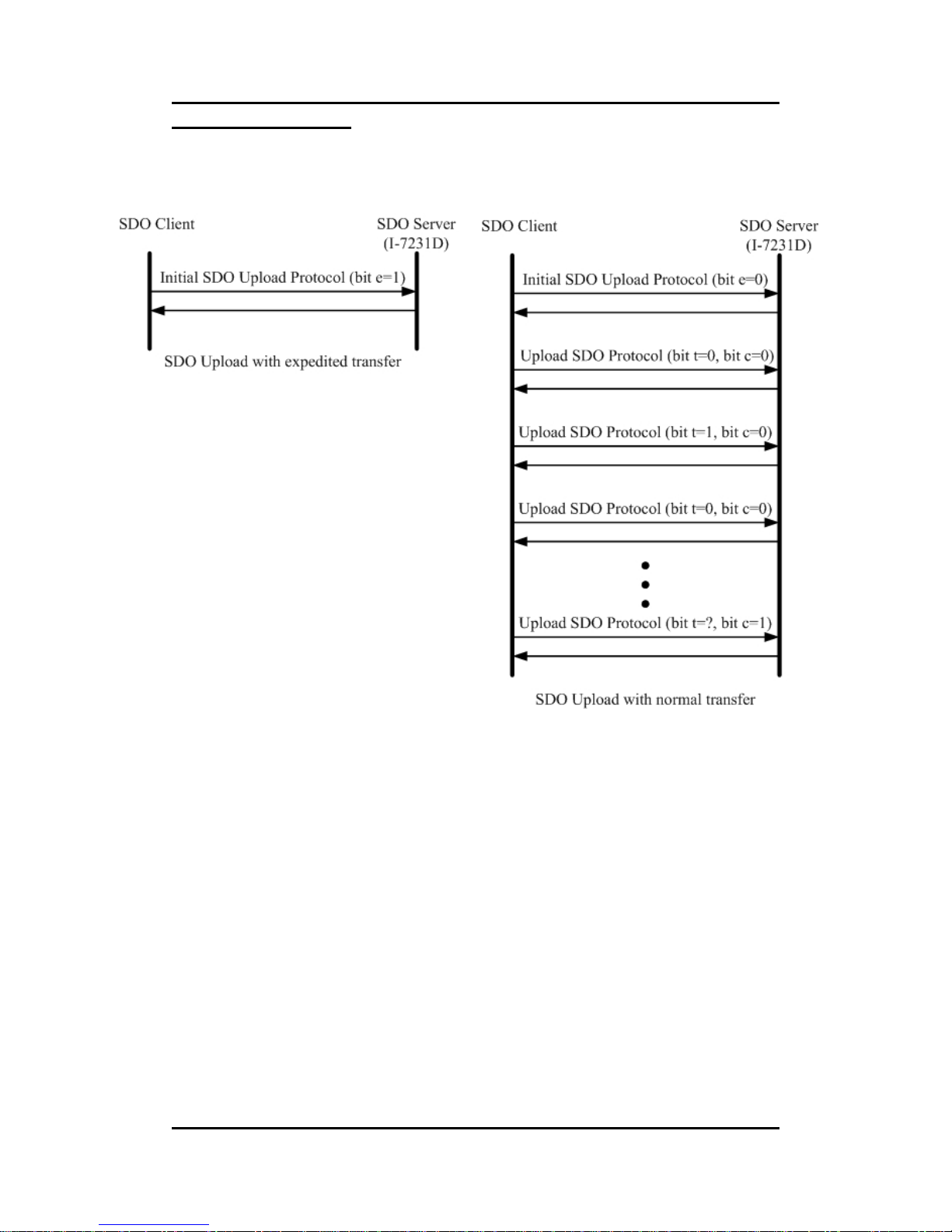
SDO Upload Example
The practical application of the SDO upload is illustrated as below.
In the following paragraph, both expedited transfer and normal
transfer are given according to the procedure described above. The method on
how to get the value stored in the object dictionary is also presented. By
means of the initiate SDO upload protocol, users can obtain how many
sub-indexes the object with index 0x1400 can support. This information is
located in the object with index 0x1400 with sub-index 00. Also, users can get
the string located in the object with index 0x1008 by using the initiate SDO
upload protocol and the upload SDO segment protocol.
Page 68
I-7231D CANopen/DCON Gateway user manual (ver. 1.04, Dec/14/2010) ------68
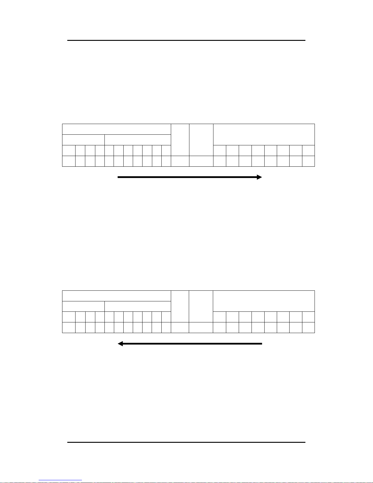
z Example for expedited transfer
Step 1. Send the RxSDO message to the I-7231D to obtain the object entry
with index 0x1400 and sub-index 00 stored in the communication profile area.
The message structure is as follows. Assume that the node ID of the I-7231D
is set to 1. Users can find the information about the object entry with index
0x1400 in chapter 6.
11-bit COB-ID (bit)
Func Code Node ID
8-byte Data (byte)
10 9 8 7 6 5 4 3 2 1 0
RTR
Data
Length
0 1 2 3 4 5 6 7
1 1 0 0 0 0 0 0 0 0 1 0 8 40 00 14 00 00 00 00 00
SDO client
SDO server
(I-7231D)
ccs
: 2
m
: 00 14 00
Because low byte needs to transfer firstly, the first byte “00” is the
low byte of 0x1400, the second byte “0x14” is the high byte of
0x1400, and the last byte “00” means the sub-index 00.
Step 2. The I-7231D will respond to the data stored in the object entry with
index 0x1400 and sub-index 00.
11-bit COB-ID (bit)
Func Code Node ID
8-byte Data (byte)
10 9 8 7 6 5 4 3 2 1 0
RTR
Data
Length
0 1 2 3 4 5 6 7
1 0 1 1 0 0 0 0 0 0 1 0 8 4F 00 14 00 02 00 00 00
SDO client
SDO server
(I-7231D)
scs
: 2
n
: 3
e
: 1
s
: 1
m
: 00 14 00
d
: 02
Because the first byte of data indicates that only the 4th byte is
valid. Therefore, the feedback value is 02.
Page 69
I-7231D CANopen/DCON Gateway user manual (ver. 1.04, Dec/14/2010) ------69
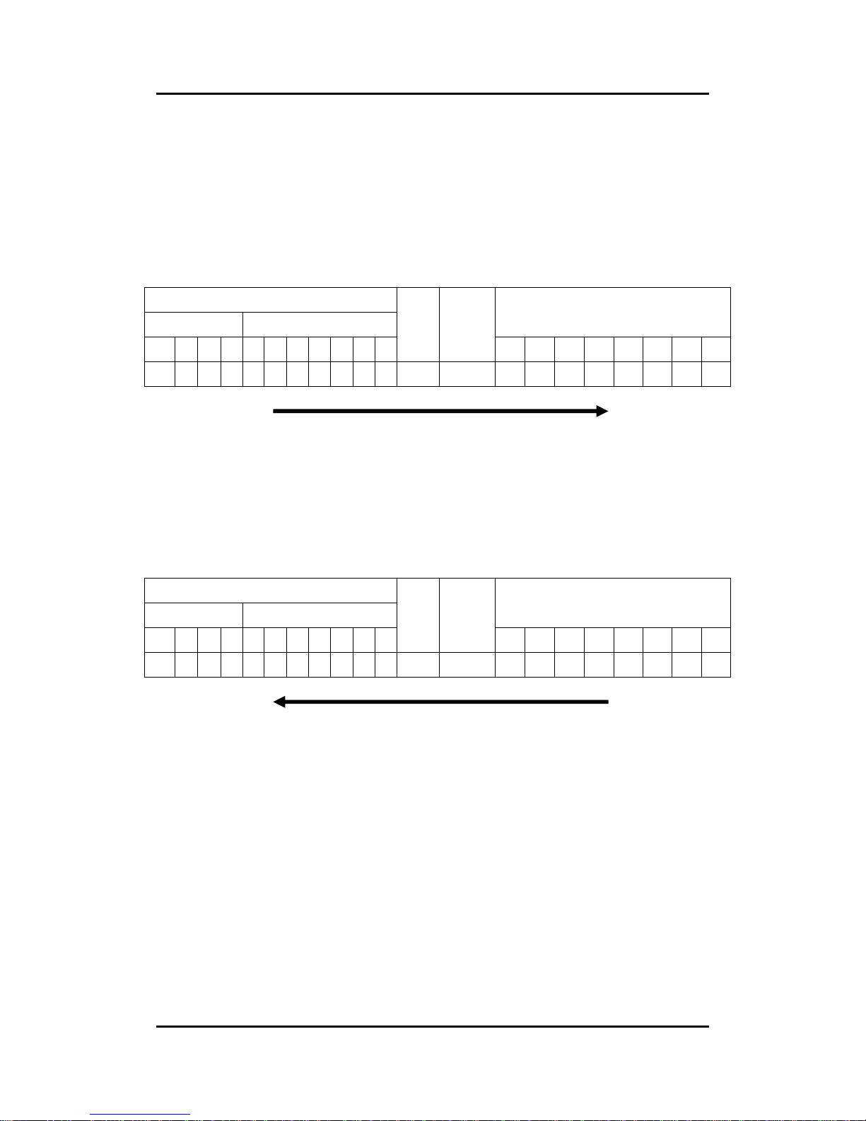
z Example for normal transfer
Step 1. Send the RxSDO message to the I-7231D to obtain the object entry
with index 0x1008 and sub-index 00 stored in the communication profile area.
The message structure is as follows. As mentioned above, the node ID for the
I-7231D is set to 1, and the information about object entry with index 0x1008 is
described in chapter 6.
11-bit COB-ID (bit)
Func Code Node ID
8-byte Data (byte)
10 9 8 7 6 5 4 3 2 1 0
RTR
Data
Length
0 1 2 3 4 5 6 7
1 1 0 0 0 0 0 0 0 0 1 0 8 40 08 10 00 00 00 00 00
SDO client
SDO server
(I-7231D)
ccs
: 2
m
: 08 10 00
Step 2. The I-7231D responds to the SDO message to indicate how many
bytes users will upload from the I-7231D.
11-bit COB-ID (bit)
Func Code Node ID
8-byte Data (byte)
10 9 8 7 6 5 4 3 2 1 0
RTR
Data
Length
0 1 2 3 4 5 6 7
1 0 1 1 0 0 0 0 0 0 1 0 8 41 08 10 00 09 00 00 00
SDO client
SDO server
(I-7231D)
scs
: 2
n
: 0
e
: 0
s
: 1
m
: 00 18 00
d
: 09
Because the first byte from the 8-byte data indicates that only the
4th byte is valid. Therefore, the feedback value is 09, and it
means that there are 9 bytes to be uploaded.
Page 70
I-7231D CANopen/DCON Gateway user manual (ver. 1.04, Dec/14/2010) ------70
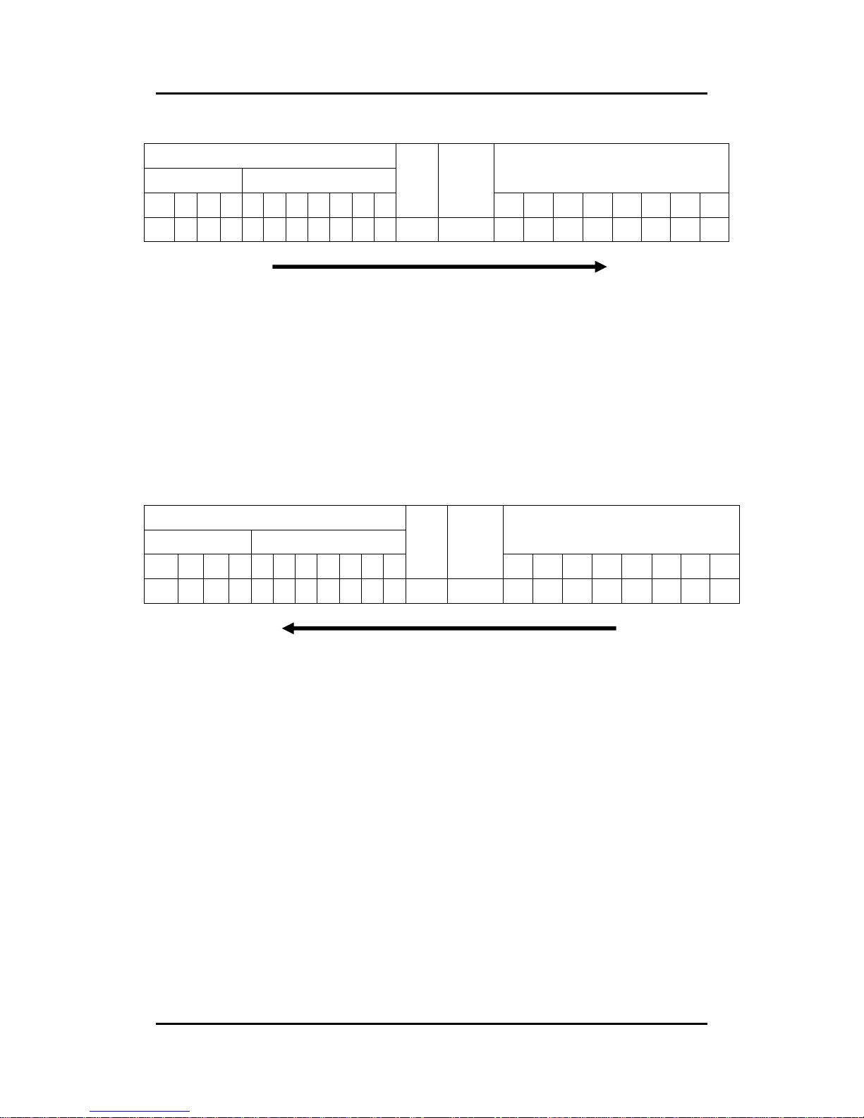
Step 3. Request the I-7231D to start the data transmission.
11-bit COB-ID (bit)
Func Code Node ID
8-byte Data (byte)
10 9 8 7 6 5 4 3 2 1 0
RTR
Data
Length
0 1 2 3 4 5 6 7
1 1 0 0 0 0 0 0 0 0 1 0 8 60 00 00 00 00 00 00 00
SDO client
SDO server
(I-7231D)
ccs
: 3
t
: 0
Step 4. The I-7231D will respond to the first 8 bytes in the index 0x1008 and
sub-index 00 object entries.
11-bit COB-ID (bit)
Func Code Node ID
8-byte Data (byte)
10 9 8 7 6 5 4 3 2 1 0
RTR
Data
Length
0 1 2 3 4 5 6 7
1 0 1 1 0 0 0 0 0 0 1 0 8 00 43 50 53 5F 44 43 4F
SDO client
SDO server
(I-7231D)
scs
: 0
t
: 0
n
: 0
c
: 0
seg-data
: 43 50 53 5F 44 43 4F
Users can check chapter 6 to see that the object entry with index
0x1008 and sub index 00 has the data type “VISIBLE_STRING”.
Therefore, users need to transfer these data values to the
corresponding ASCII character. After transformation, they are
“CPS_DCO”.
Page 71
I-7231D CANopen/DCON Gateway user manual (ver. 1.04, Dec/14/2010) ------71
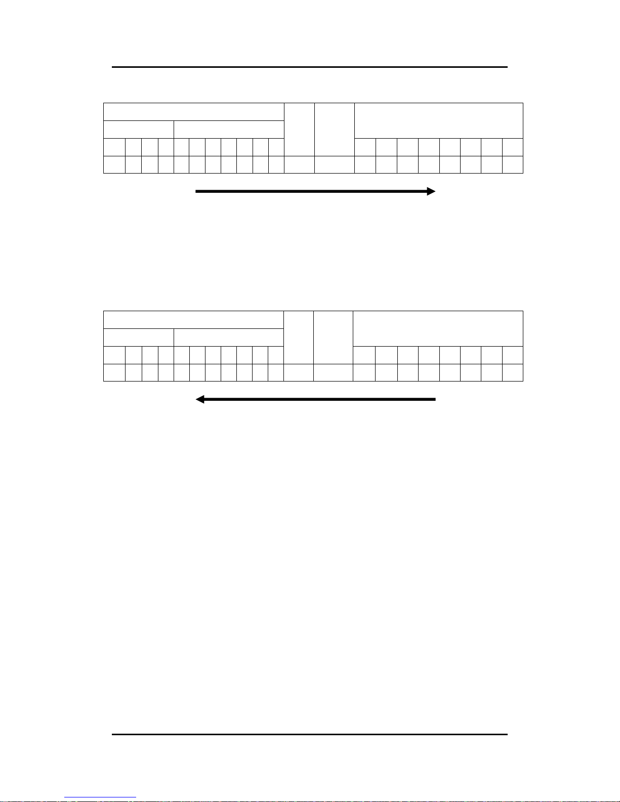
Step 5. Request the I-7231D to transmit the rest of the data.
11-bit COB-ID (bit)
Func Code Node ID
8-byte Data (byte)
10 9 8 7 6 5 4 3 2 1 0
RTR
Data
Length
0 1 2 3 4 5 6 7
1 1 0 0 0 0 0 0 0 0 1 0 8 70 00 00 00 00 00 00 00
SDO client
SDO server
(I-7231D)
ccs
: 3
t
: 1
Step 6. Receive the rest of the data from the SDO server.
11-bit COB-ID (bit)
Func Code Node ID
8-byte Data (byte)
10 9 8 7 6 5 4 3 2 1 0
RTR
Data
Length
0 1 2 3 4 5 6 7
1 0 1 1 0 0 0 0 0 0 1 0 8 1B 4E 00 00 00 00 00 00
SDO client
SDO server
(I-7231D)
scs
: 0
t
: 1
n
: 5
c
: 1
seg-data
: 4E 00
Transfer the value of 0x4E and 0x00 to the corresponding ASCII
character. After transformation, it means “N ”.
Page 72
I-7231D CANopen/DCON Gateway user manual (ver. 1.04, Dec/14/2010) ------72
5.1.2 SDO Block Upload
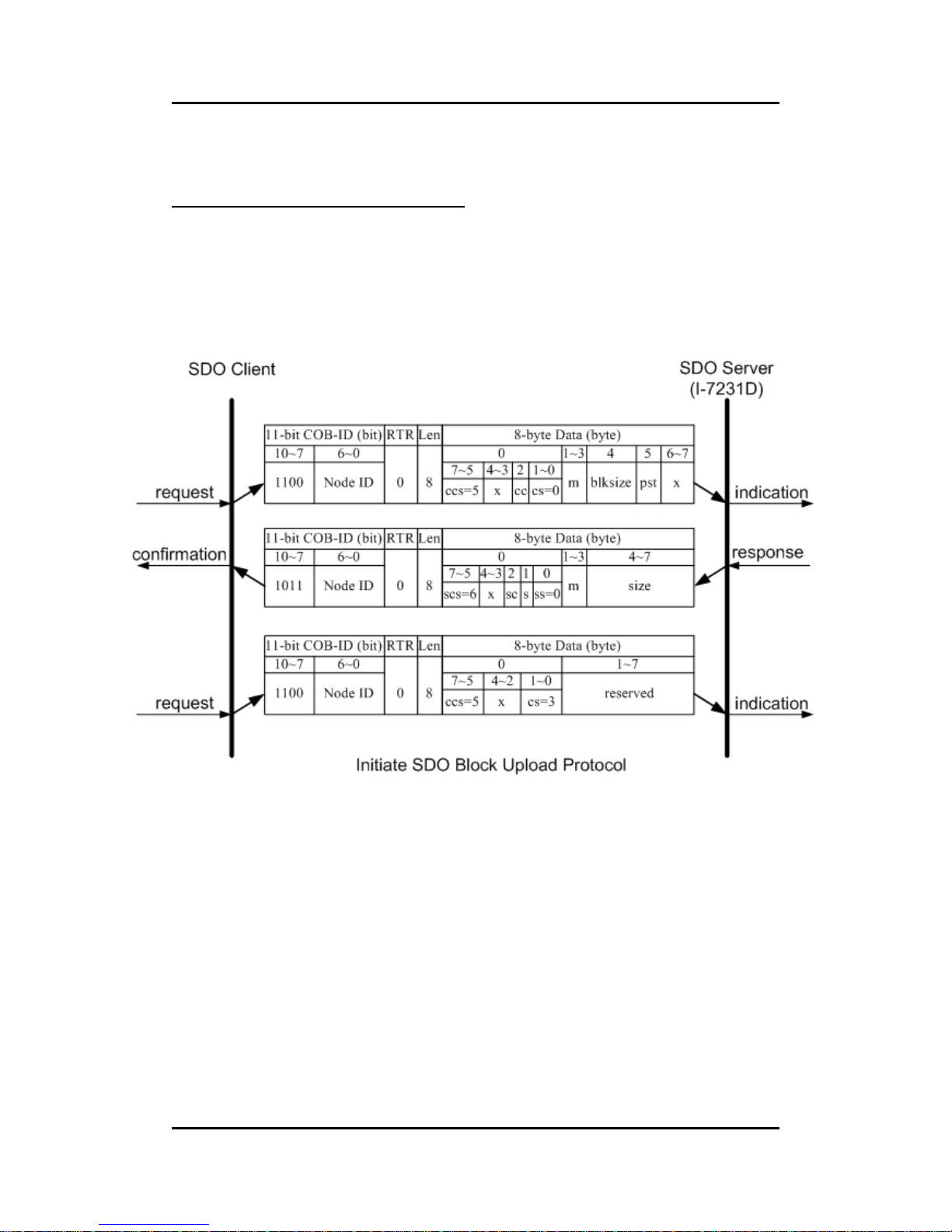
Initiate SDO Block Upload Protocol
The SDO Block Upload is usually used for large data transmission. At the
beginning of the SDO Block Upload, the Initiate SDO Block Upload protocol is
needed. This protocol is described below.
Page 73

I-7231D CANopen/DCON Gateway user manual (ver. 1.04, Dec/14/2010) ------73
ccs
: client command specifier
5: block upload
scs
: server command specifier
6: block upload.
cs
: client subcommand
0: initiate upload request
3: start upload
ss
: server subcommand
0: initiate upload response
m
: multiplexor
It represents the index/sub-index of the data to be transfer by the
SDO.
cc
: client CRC support
cc=0: Client does not support generating CRC on data.
cc=1: Client supports generating CRC on data.
sc
: server CRC support
sc=0: Server does not support generating CRC on data.
sc=1: Server supports generating CRC on data.
pst
: Protocol Switch Threshold in bytes to change the SDO transfer
protocol
pst=0: change of transfer protocol not allowed
pst>0: If the size of the data in bytes that has to be uploaded is
less or equal pst, the server can optionally switch to the ‘SDO
Upload Protocol’ by transmitting the server response of the ‘SDO
Upload Protocol’.
s
: size indicator
0: Data set size is not indicated.
1: Data set size is indicated.
size
: upload size in byes
s=0: Size is reserved for further use, always 0.
s=1: Size contains the number of bytes to be uploaded. Byte 4
contains the LSB and byte 7 is the MSB.
blksize
:
number of segments per block with 0 < blksize < 128
x
: not used, always 0
reserved
: reserved for further use , always 0
Page 74
I-7231D CANopen/DCON Gateway user manual (ver. 1.04, Dec/14/2010) ------74
Upload SDO Block Segment Protocol
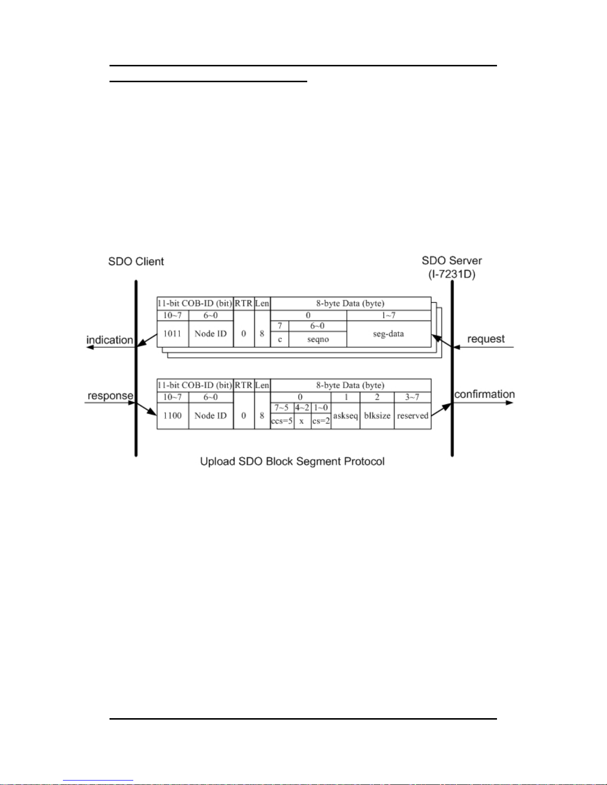
After finish the Initiate SDO Block protocol, the SDO server starts to
respond to the data by using the Upload SDO Block Segment protocol. Each
block contains 1 segment for minimum and 127 segments for maximum. One
segment consists of 1~7 bytes. Only one block can be transmitted during an
Upload SDO Block Segment protocol. The SDO server can send a maximum
of 127 blocks by using 127 Upload SDO Block Segment protocols. Here is the
structure of the Upload SDO Block Segment protocol.
Page 75

I-7231D CANopen/DCON Gateway user manual (ver. 1.04, Dec/14/2010) ------75
ccs
: client command specifier
5: block upload
cs
: client subcommand
2: block upload response
c
: It indicates whether there are still more segments to be
uploaded.
0: more segments to be uploaded
1: no more segments to be uploaded , enter ‘End block upload’
phase
seqno
:
sequence number of segment, 0 < seqno < 128
seg-data
: It is at most 7 bytes of segment data to be uploaded.
ackseq
: sequence number of last segment that was received
successfully during the last block upload
If ackseq is set to 0, the client indicates the server that the
segment with the sequence number 1 was not received correctly
and all segments have to be retransmitted by the server.
blksize
: number of segments per block that has to be used by server for
the following block upload with 0 < blksize < 128
x
: not used, always 0
reserved
: reserved for further use , always 0
Page 76
I-7231D CANopen/DCON Gateway user manual (ver. 1.04, Dec/14/2010) ------76
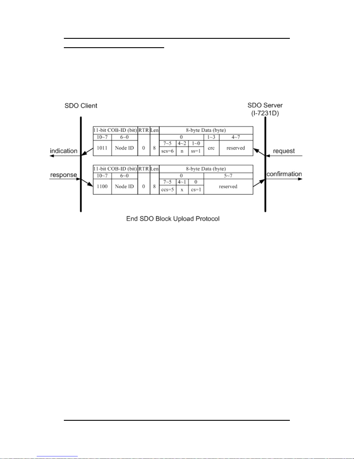
End SDO Block Upload Protocol
The End SDO Block Upload protocol is used for finishing the SDO Block
upload, and is shown in the following figure.
Page 77

I-7231D CANopen/DCON Gateway user manual (ver. 1.04, Dec/14/2010) ------77
ccs
: client command specifier
5: block upload
scs
: server command specifier
6: block upload
cs
: client subcommand
1: end block upload request
ss
: server subcommand
1: end block upload response
n
: It indicates the number of bytes in the last segment of the last
block that do not contain data. Bytes [8-n,7] do not contain
segment data.
crc
: 16 bit Cyclic Redundancy Checksum (CRC) for the whole data
set.
The algorithm for generating the CRC is as follows.
x^16+x^12+x^5+1
CRC is only valid if in Initiate Block Upload cc and sc are set to
1. Otherwise crc has to be set to 0. For I-7231D, it is not support
CRC check mechanism.
x
: not used, always 0
reserved
: reserved for further use , always 0
Page 78
I-7231D CANopen/DCON Gateway user manual (ver. 1.04, Dec/14/2010) ------78
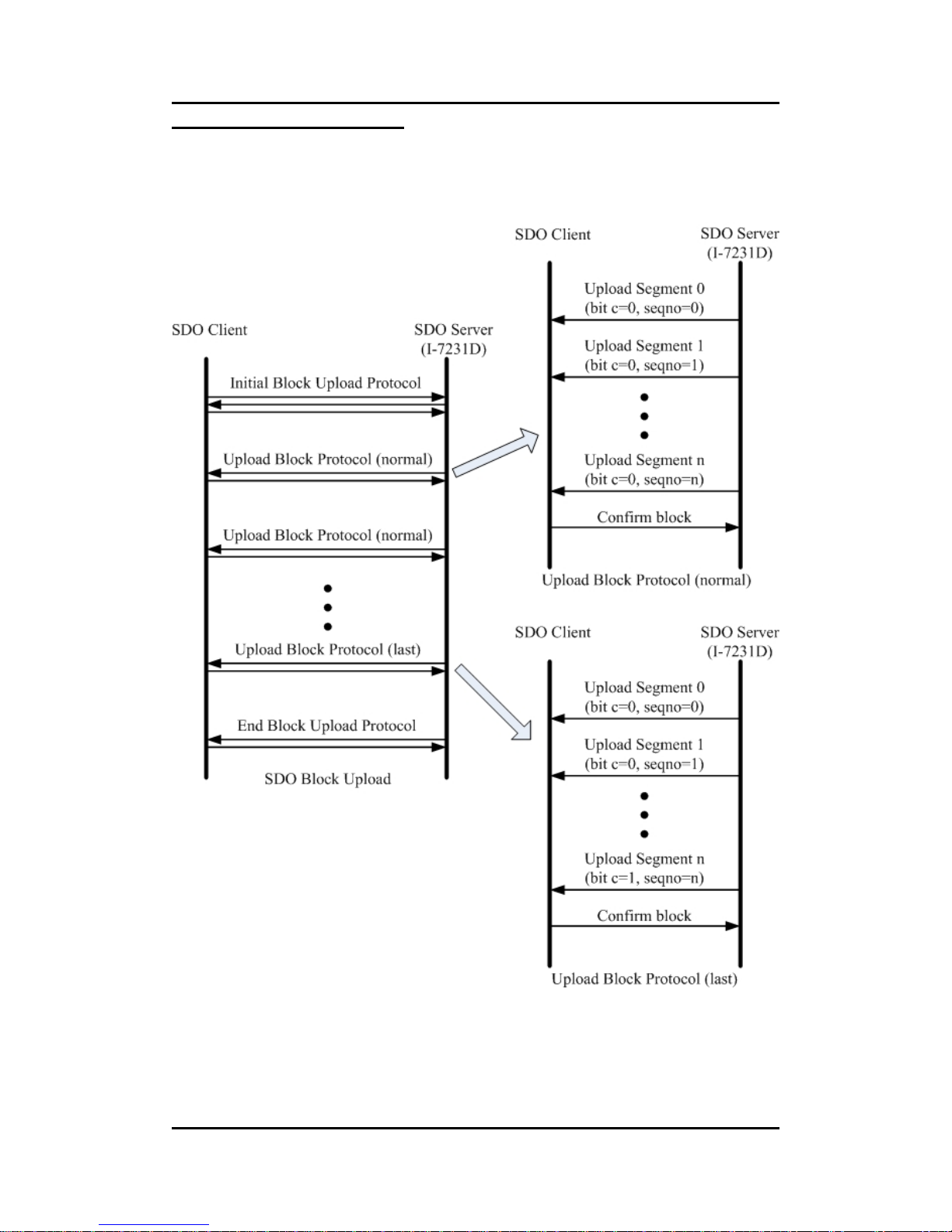
SDO Block Upload Example
The following figure indicates the general procedure for applying the SDO
Block upload.
Page 79
I-7231D CANopen/DCON Gateway user manual (ver. 1.04, Dec/14/2010) ------79
By following this procedure, we provide a demo for obtaining the value of
the index 0x1008 and sub-index 00 object entry.
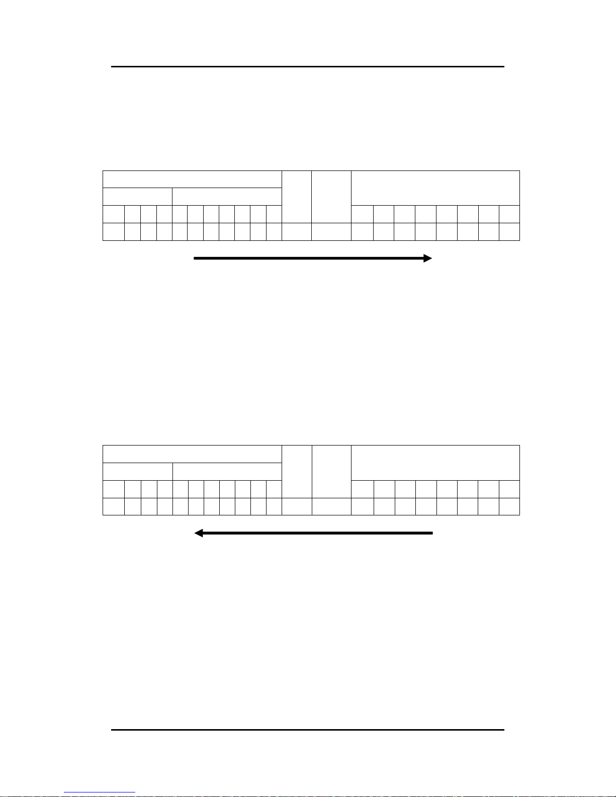
Step 1. Request the I-7231D to transmit the data by using the SDO Block
Upload method.
11-bit COB-ID (bit)
Func Code Node ID
8-byte Data (byte)
10 9 8 7 6 5 4 3 2 1 0
RTR
Data
Length
0 1 2 3 4 5 6 7
1 1 0 0 0 0 0 0 0 0 1 0 8 A0 08 10 00 7F 00 00 00
SDO client
SDO server
(I-7231D)
ccs
: 5
cc
: 0
cs
: 0
m
: 08 10 00
blksize
: 7F
Each block contains 127 segments.
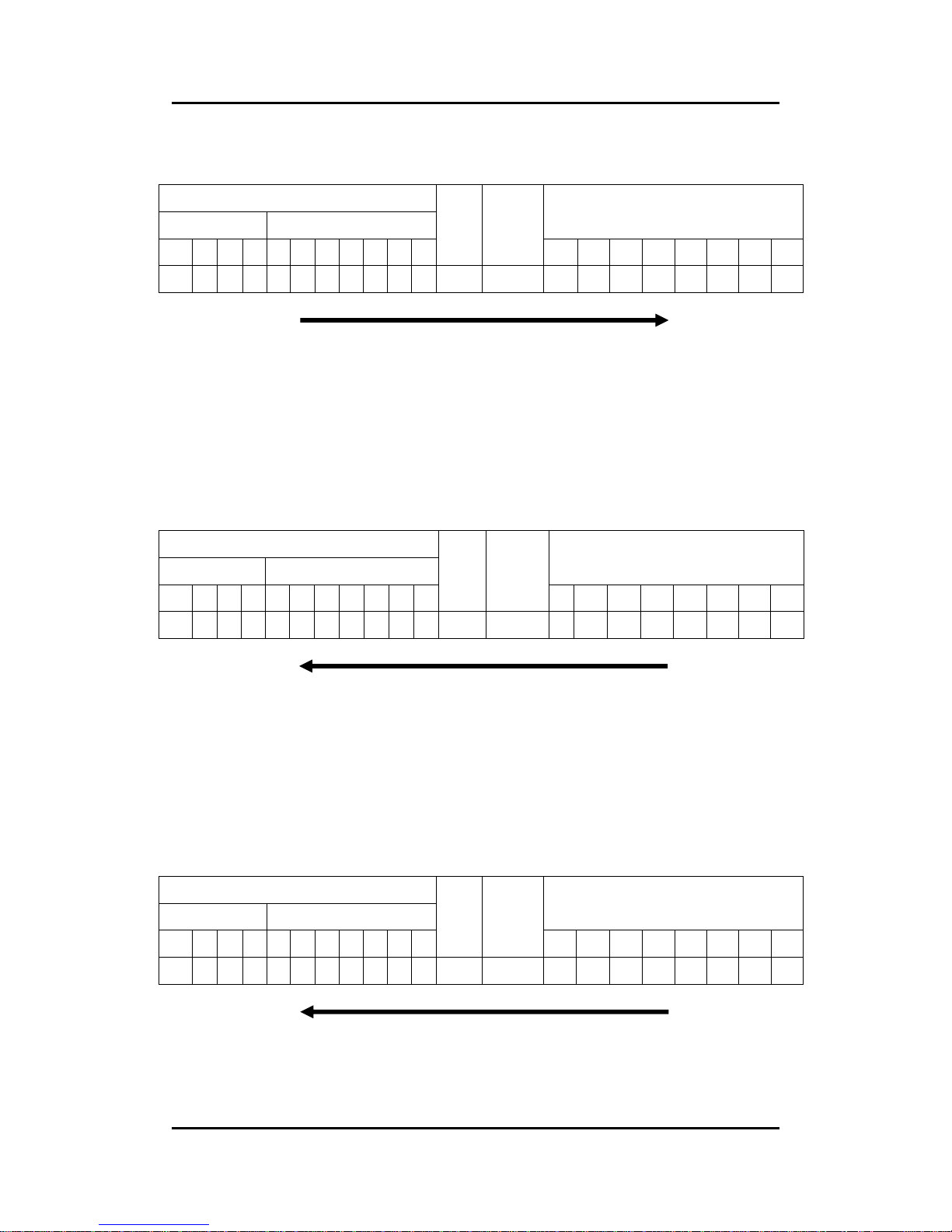
Step 2. The I-7231D confirms the requirement with the Initiate SDO Block
Upload protocol.
11-bit COB-ID (bit)
Func Code Node ID
8-byte Data (byte)
10 9 8 7 6 5 4 3 2 1 0
RTR
Data
Length
0 1 2 3 4 5 6 7
1 0 1 1 0 0 0 0 0 0 1 0 8 C2 08 10 00 09 00 00 00
SDO client
SDO server
(I-7231D)
scs
: 6
sc
: 0
s
: 1
ss
: 0
m
: 08 10 00
size
: 09
The I-7231D will response 9 bytes data during the SDO Block
Upload.
Page 80
I-7231D CANopen/DCON Gateway user manual (ver. 1.04, Dec/14/2010) ------80
Step 3. Send the message to finish the Initiate SDO Block Upload protocol,
and inform the I-7231D to start the data transmission.
11-bit COB-ID (bit)
Func Code Node ID
8-byte Data (byte)
10 9 8 7 6 5 4 3 2 1 0
RTR
Data
Length
0 1 2 3 4 5 6 7
1 1 0 0 0 0 0 0 0 0 1 0 8 A3 00 00 00 00 00 00 00
SDO client
SDO server
(I-7231D)
ccs
: 5
cs
: 3
Step 4. The I-7231D responds to the first 7 bytes of data by using the Upload
SDO Block Segment protocol.
11-bit COB-ID (bit)
Func Code Node ID
8-byte Data (byte)
10 9 8 7 6 5 4 3 2 1 0
RTR
Data
Length
0 1 2 3 4 5 6 7
1 0 1 1 0 0 0 0 0 0 1 0 8 1 43 50 53 5F 44 43 4F
SDO client
SDO server
(I-7231D)
c
: 0
seqno
: 1
seg-data
: 43 50 53 5F 44 43 4F
Step 5. The I-7231D transmits the rest of the data.
11-bit COB-ID (bit)
Func Code Node ID
8-byte Data (byte)
10 9 8 7 6 5 4 3 2 1 0
RTR
Data
Length
0 1 2 3 4 5 6 7
1 0 1 1 0 0 0 0 0 0 1 0 8 82 4E 00 00 00 00 00 00
SDO client
SDO server
(I-7231D)
c
: 1
seqno
: 2
seg-data
: 4E 00
Page 81
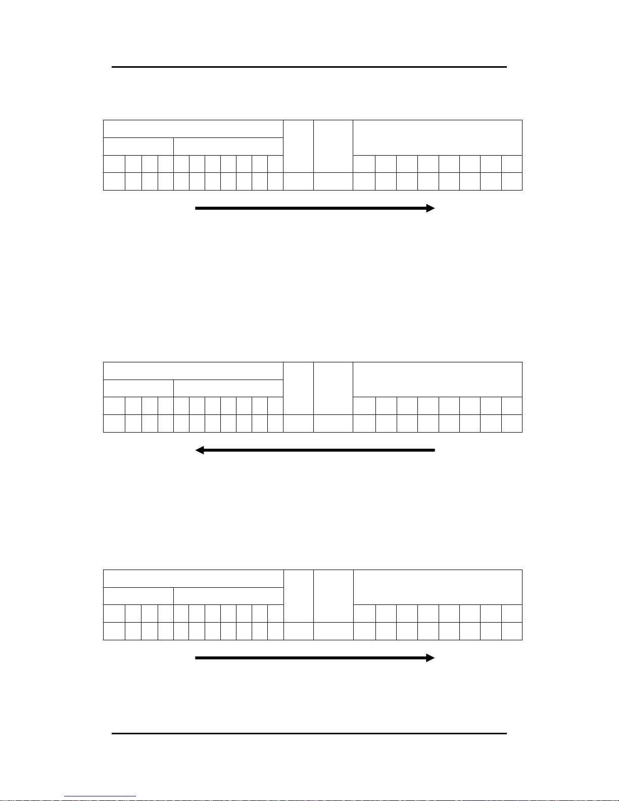
I-7231D CANopen/DCON Gateway user manual (ver. 1.04, Dec/14/2010) ------81
Step 6. Afterwards, users send a message to confirm the receiving data
transmitted from the I-7231D.
11-bit COB-ID (bit)
Func Code Node ID
8-byte Data (byte)
10 9 8 7 6 5 4 3 2 1 0
RTR
Data
Length
0 1 2 3 4 5 6 7
1 1 0 0 0 0 0 0 0 0 1 0 8 A2 02 7F 00 00 00 00 00
SDO client
SDO server
(I-7231D)
ccs
: 5
cs
: 2
ackseq
: 2
blksize
: 7F
Step 7. When the reception confirmation is ok, the I-7231D will send a
message to enter the End SDO Block Upload protocol.
11-bit COB-ID (bit)
Func Code Node ID
8-byte Data (byte)
10 9 8 7 6 5 4 3 2 1 0
RTR
Data
Length
0 1 2 3 4 5 6 7
1 0 1 1 0 0 0 0 0 0 1 0 8 D5 00 00 00 00 00 00 00
SDO client
SDO server
(I-7231D)
scs
: 6
n
: 5
ss
: 1
Step 8. Users send a message to finish the End SDO Block Upload protocol.
11-bit COB-ID (bit)
Func Code Node ID
8-byte Data (byte)
10 9 8 7 6 5 4 3 2 1 0
RTR
Data
Length
0 1 2 3 4 5 6 7
1 1 0 0 0 0 0 0 0 0 1 0 8 A1 00 00 00 00 00 00 00
SDO client
SDO server
(I-7231D)
ccs
: 5
cs
: 1
Page 82
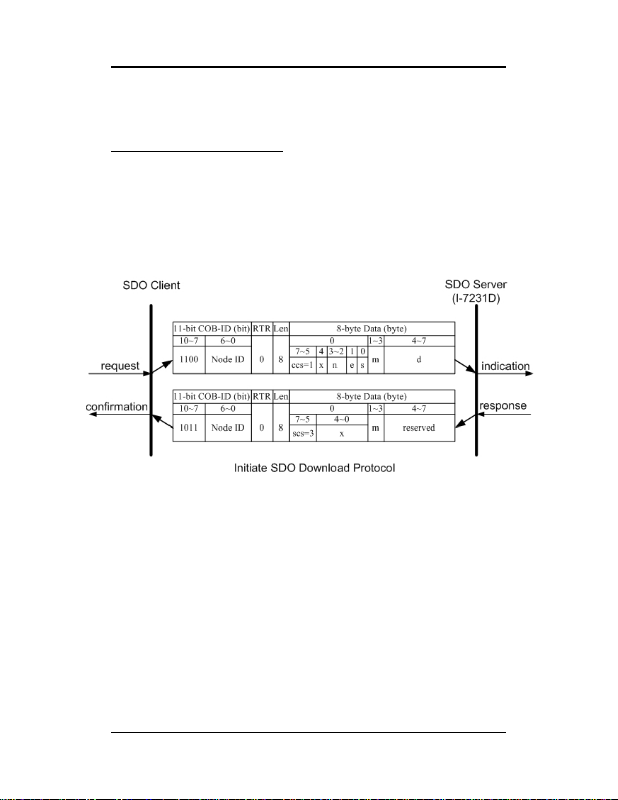
I-7231D CANopen/DCON Gateway user manual (ver. 1.04, Dec/14/2010) ------82
5.1.3 Download
Initiate SDO Download Protocol
The download modes are similar to the upload modes, but different in
some parameters in their SDO messages. They are also separated into two
steps. If the download data length is less than 4 bytes, the download action will
finish in the download initialization protocol. Or, the download segment
protocol will be needed. These two protocols are shown below.
Page 83

I-7231D CANopen/DCON Gateway user manual (ver. 1.04, Dec/14/2010) ------83
ccs
: client command specifier
1: initiate download request
scs
: server command specifier
3: initiate download response
n
:
Only valid if e = 1 and s = 1, otherwise 0. If valid, it indicates the
number of bytes in d that do not contain data. Bytes [8-n, 7] do
not contain segment data.
e
: transfer type
0: normal transfer
1: expedited transfer
If the e=1, it means that the data of the object are equal or less
than 4 bytes, and only initiate SDO download protocol is needed.
If e=0, the download SDO protocol is necessary.
s
: size indicator
0: data set size is not indicated
1: data set size is indicated
m
: multiplexer
It represents the index/sub-index of the data to be transfer by the
SDO.
d
: data
e=0,s=0: d Is reserved for further use.
e=0,s=1: d contains the number of bytes to be downloaded, and
byte 4 contains the least significant bit, and byte 7
contains the most significant bit.
e=1,s=1: d contains the data of length 4-n to be downloaded, the
encoding depends on the type of the data referenced
by index and sub-index.
e=1,s=0: d contains unspecified number of bytes to be
downloaded.
x
: not used, always 0
reserved
: reserved for further use , always 0
Page 84
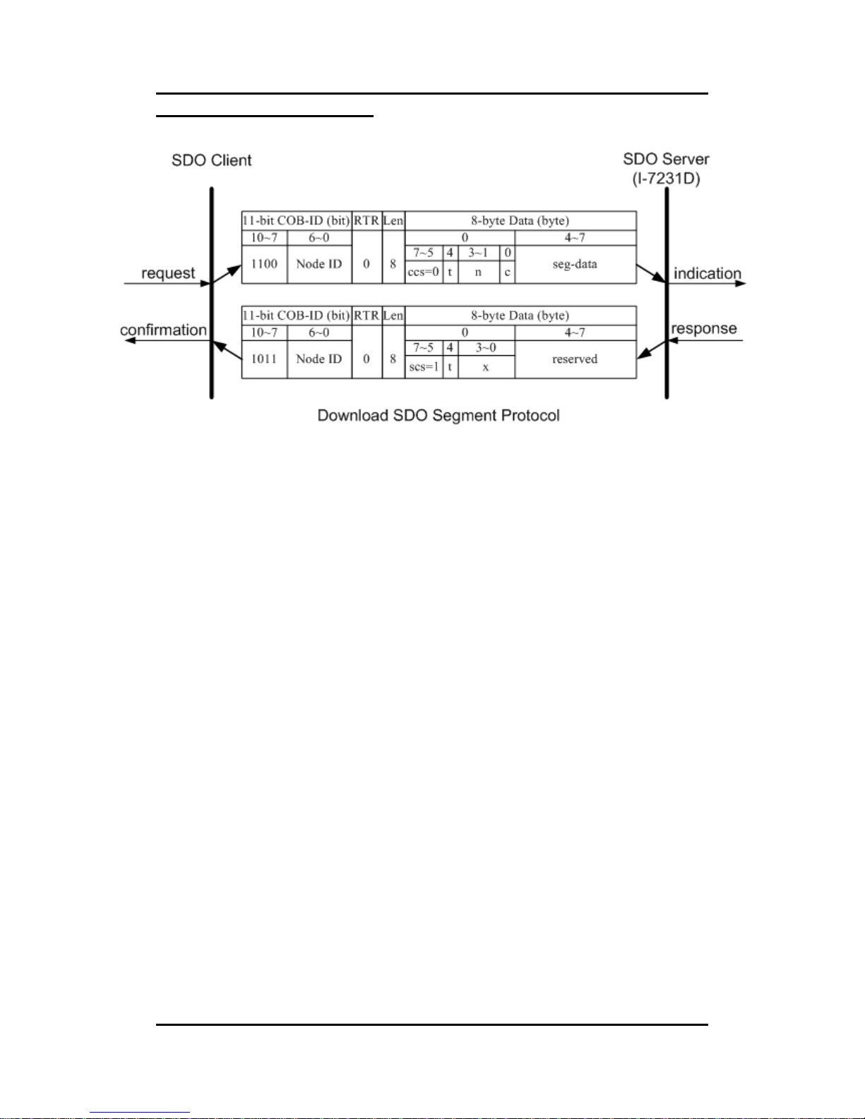
I-7231D CANopen/DCON Gateway user manual (ver. 1.04, Dec/14/2010) ------84
Download Segment Protocol
ccs
: client command specifier
0: download segment request
scs
: server command specifier
1: download segment response
seg-data
: It is at most 7 bytes of segment data to be downloaded. The
encoding depends on the type of the data referenced by index
and sub-index.
n
:
It indicates the number of bytes in segment data that do not
contain segment data. Bytes [8-n, 7] do not contain segment
data. n = 0 if no segment size is indicated.
c
: It indicates whether there are still more segments to be
downloaded.
0 more segments to be downloaded
1: no more segments to be downloaded
t
: toggle bit
This bit must alternate for each subsequent segment that is
downloaded. The first segment will have the toggle-bit set to 0.
The toggle bit will be equal for the request and the response
message.
x
: not used, always 0
reserved
: reserved for further use , always 0
Page 85
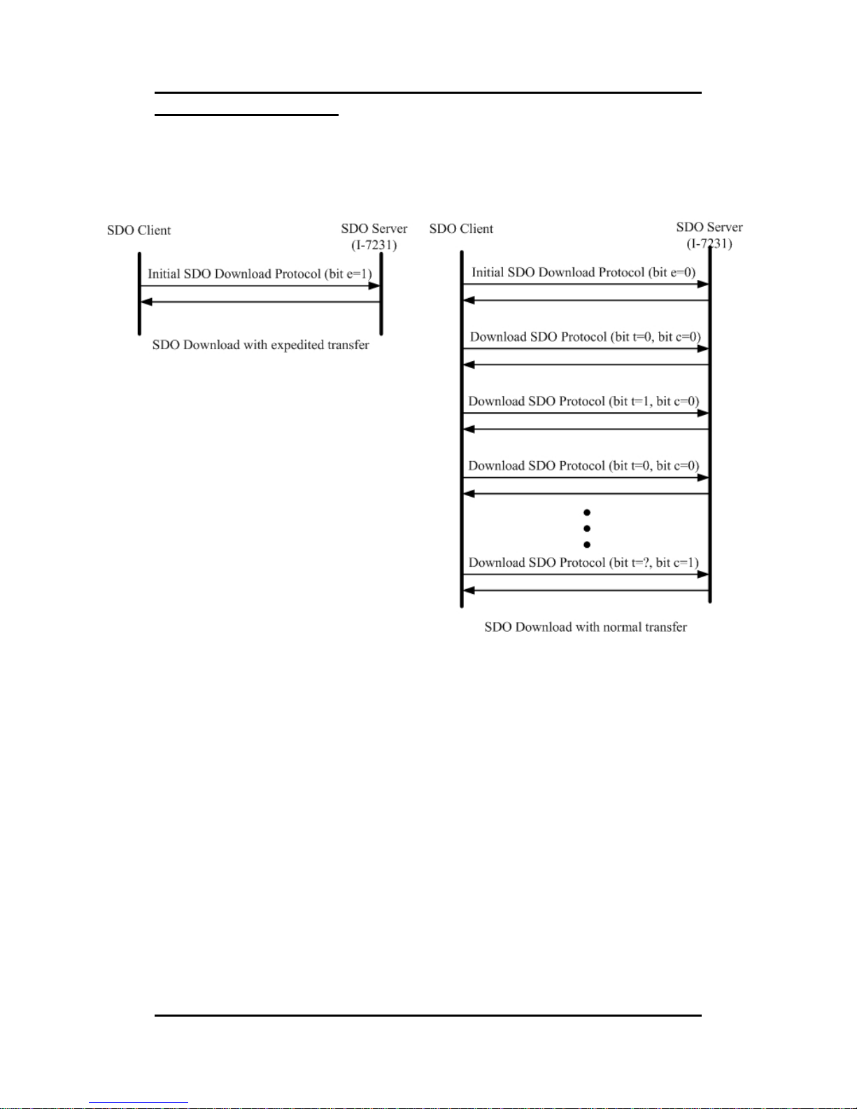
I-7231D CANopen/DCON Gateway user manual (ver. 1.04, Dec/14/2010) ------85
SDO Download Example
When the SDO download example has been applied, the procedure in the
below figure may be applied.
Since all of those object entries, which can be written, in the I-7231D are
equal or less than 4 bytes, we can only provide the demo for expedited
transfer.
Page 86
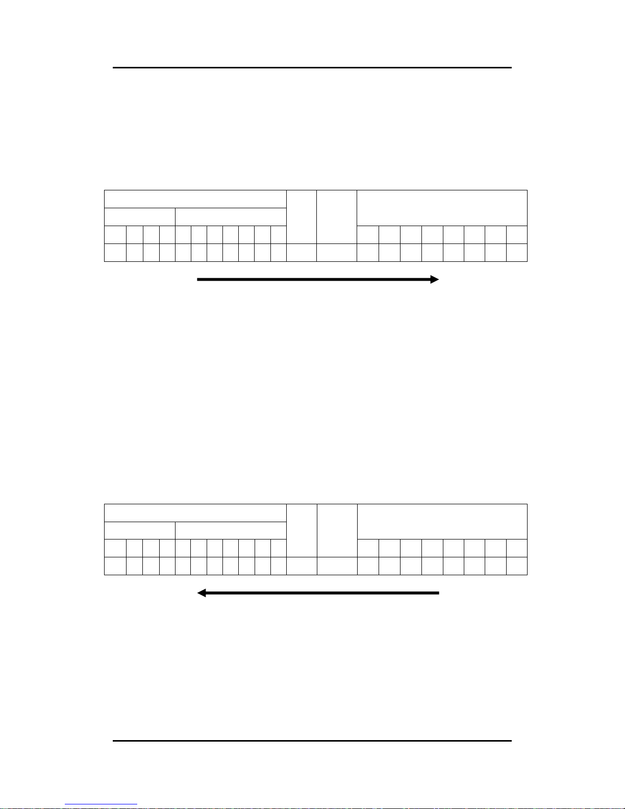
I-7231D CANopen/DCON Gateway user manual (ver. 1.04, Dec/14/2010) ------86
z Example for expedited transfer
Step 1. Send the Rx SDO message to the I-7231D to access the object entry
with index 0x1400 and sub-index 02 stored in the communication profile area.
Here, change the value of this object entry to 5. Assume that the node ID for
the I-7231D is set to 1.
11-bit COB-ID (bit)
Func Code Node ID
8-byte Data (byte)
10 9 8 7 6 5 4 3 2 1 0
RTR
Data
Length
0 1 2 3 4 5 6 7
1 1 0 0 0 0 0 0 0 0 1 0 8 2F 00 14 02 05 00 00 00
SDO client
SDO server
(I-7231D)
ccs
: 1
n
: 3
e
: 1
s
: 1
m
: 00 14 02
d
: 05
Step 2. The I-7231D will response the message to finish the data download.
Afterwards, users can use upload methods mentioned before to read back the
value for confirmation.
11-bit COB-ID (bit)
Func Code Node ID
8-byte Data (byte)
10 9 8 7 6 5 4 3 2 1 0
RTR
Data
Length
0 1 2 3 4 5 6 7
1 0 1 1 0 0 0 0 0 0 1 0 8 60 00 14 02 00 00 00 00
SDO client
SDO server
(I-7231D)
scs
: 3
m
: 00 14 00
Page 87
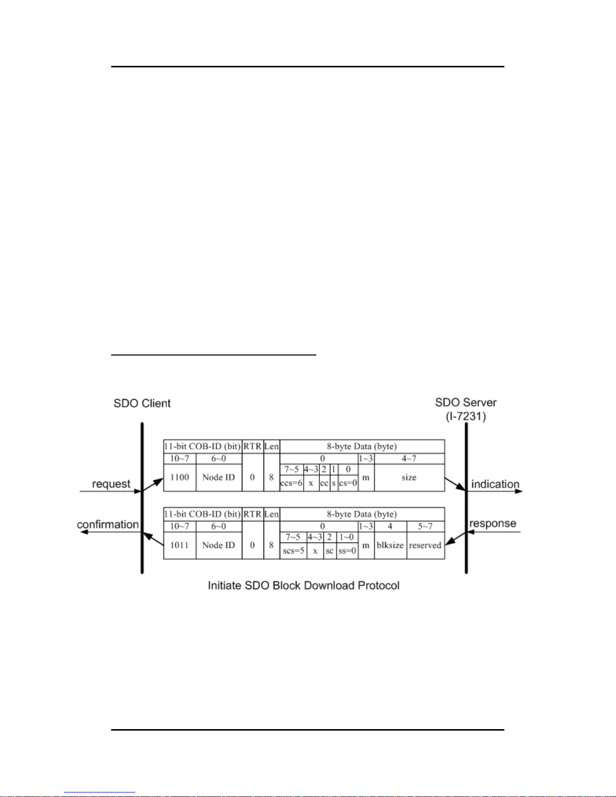
I-7231D CANopen/DCON Gateway user manual (ver. 1.04, Dec/14/2010) ------87
5.1.4 SDO Block Download
The procedure of SDO Block Download is similar with the SDO Block
Upload. There are three steps during the SDO Block Download. The Initiate
SDO Block Download protocol is the beginning protocol for SDO Block
Download. In this protocol, the SDO server and SDO client communicate each
other to prepare the necessary information. Afterwards, the SDO Block
Download protocol is used. And, SDO client start to send data to SDO server.
After finishing the data transmission, the client and server will use the End
SDO Block protocol to terminate the SDO Block Download. The following
figures are the structures for the three protocols.
Initiate SDO Block Download Protocol
Page 88

I-7231D CANopen/DCON Gateway user manual (ver. 1.04, Dec/14/2010) ------88
ccs
: client command specifier
6: block download
scs
: server command specifier
5: block download
s
: size indeicator
0: Data set size is not indicated.
1: Data set size is indicated.
cs
: client subcommand
0: initiate download request
ss
: server subcommand
0: initiate download response
cc
: client CRC support
cc=0: Client does not support generating CRC on data.
cc=1: Client supports generating CRC on data.
sc
: server CRC support
sc=0: Server does not support generating CRC on data.
sc=1: Server supports generating CRC on data.
m
: multiplexor
It represents the index/sub-index of the data to be transfer by the
SDO.
size
: download size in byes
s=0: Size is reserved for further use, always 0.
s=1: Size contains the number of bytes to be downloaded. Byte
4 contains the LSB and byte 7 is the MSB.
blksize
:
number of segments per block with 0 < blksize < 128
x
: not used, always 0
reserved
: reserved for further use , always 0
Page 89
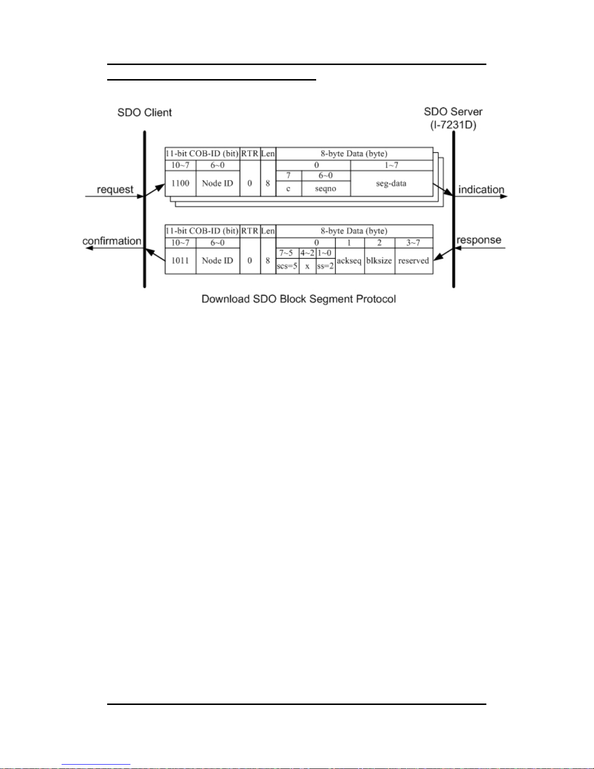
I-7231D CANopen/DCON Gateway user manual (ver. 1.04, Dec/14/2010) ------89
Download SDO Block Segment Protocol
scs
: server command specifier
5: block download
ss
: server subcommand
0: initiate download response
c
: It indicates whether there are still more segments to be
downloaded.
0: more segments to be downloaded
1: no more segments to be downloaded , enter ‘End block
download’ phase
seqno
:
sequence number of segment, 0 < seqno < 128
seg-data
: It is at most 7 bytes of segment data to be downloaded.
ackseq
: sequence number of last segment that was received
successfully during the last block download
If ackseq is set to 0, the server indicates the client that the
segment with the sequence number 1 was not received correctly
and all segments have to be retransmitted by the client.
blksize
: number of segments per block that has to be used by client for
the following block download with 0 < blksize < 128
x
: not used, always 0
reserved
: reserved for further use , always 0
Page 90
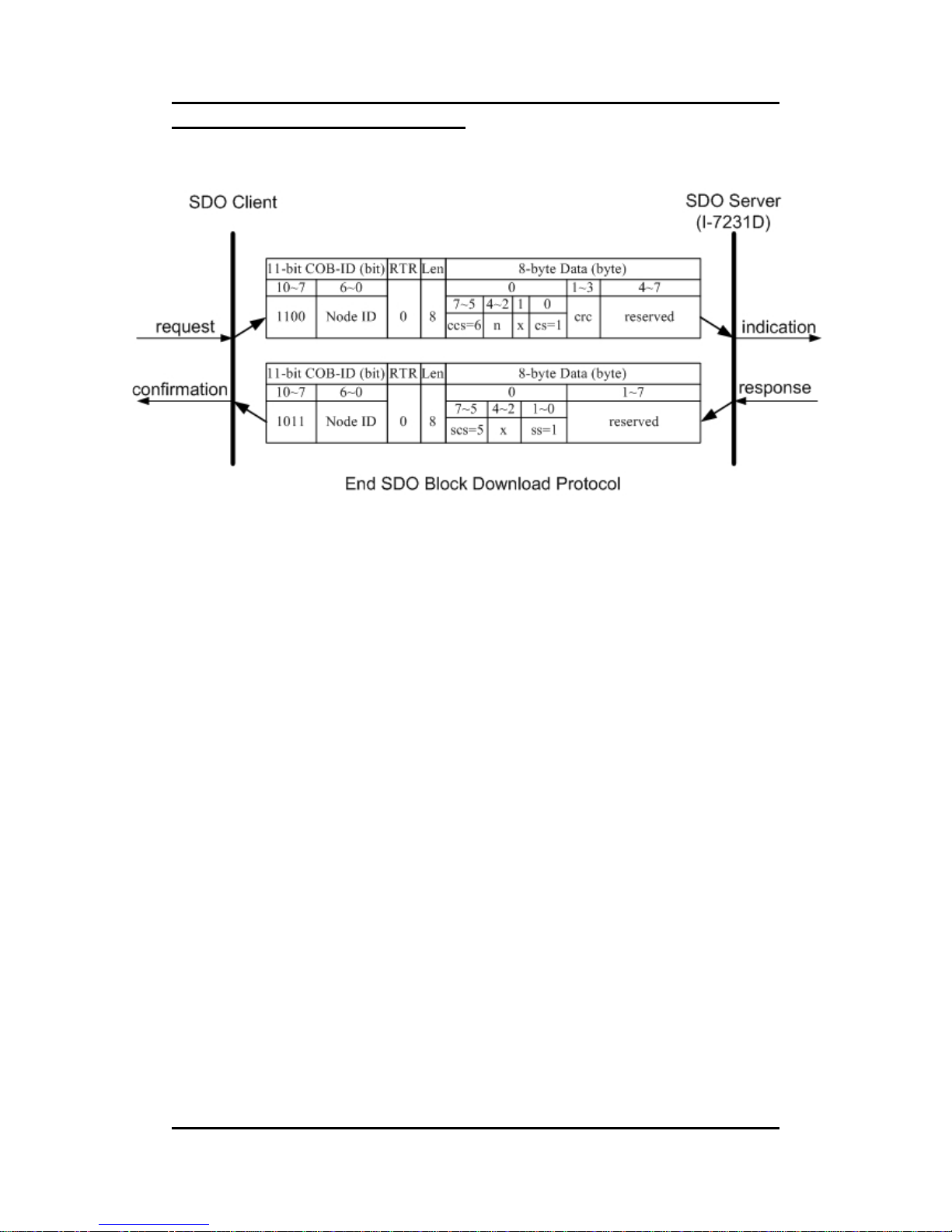
I-7231D CANopen/DCON Gateway user manual (ver. 1.04, Dec/14/2010) ------90
End SDO Block Download Protocol
ccs
: client command specifier.
6: block download
scs
: server command specifier.
5: block download
cs
: client subcommand
1: end block download request
ss
: server subcommand
1: end block download response
n
: It indicates the number of bytes in the last segment of the last
block that do not contain data. Bytes [8-n,7] do not contain
segment data.
crc
: 16 bit Cyclic Redundancy Checksum (CRC) for the whole data
set.
The algorithm for generating the CRC is as follows.
x^16+x^12+x^5+1
CRC is only valid if in Initiate Block Download cc and sc are set
to 1. Otherwise, crc has to be set to 0. For I-7231D, it is not
support CRC check mechanism.
X
: not used, always 0
reserved
: reserved for further use , always 0
Page 91
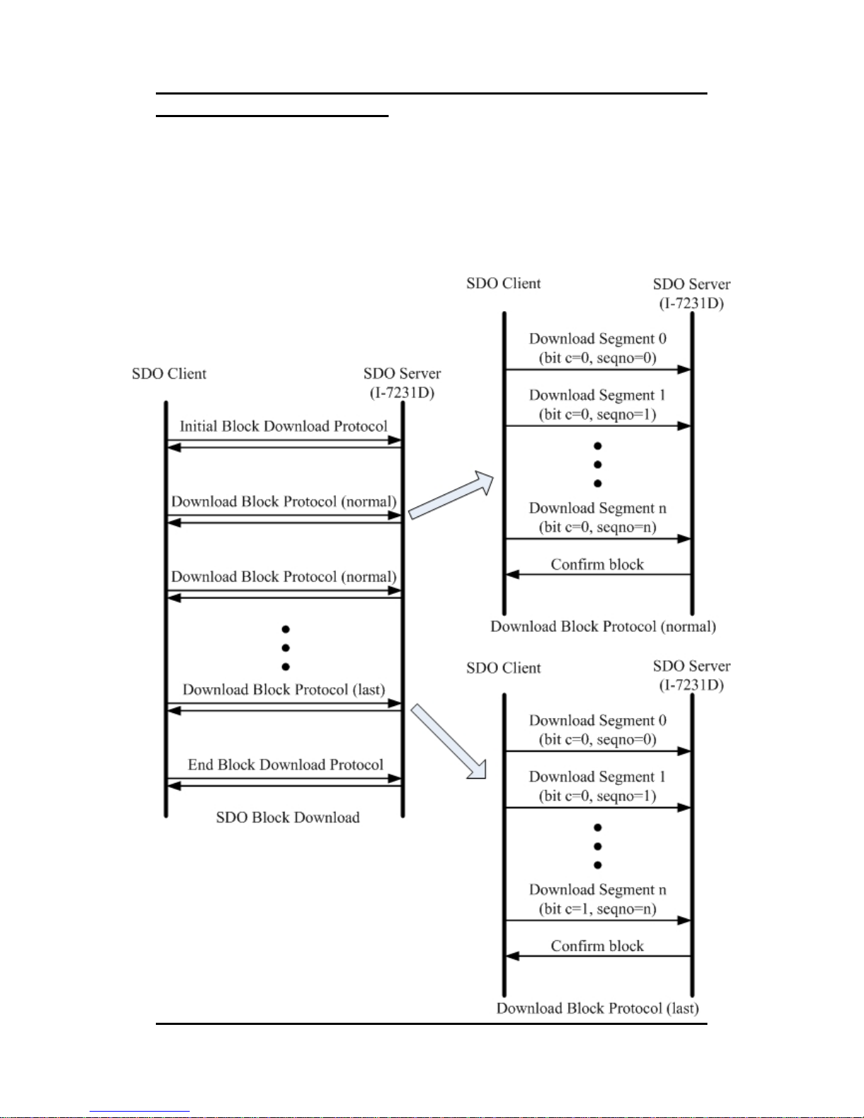
I-7231D CANopen/DCON Gateway user manual (ver. 1.04, Dec/14/2010) ------91
SDO Block Download Example
In this demo, the value of the object entry with index 0x1400 and
sub-index 0x02 will be changed to 5 by using the SDO Block Download
communication method. When the SDO Block Download is running, the
procedure looks as follows.
Page 92
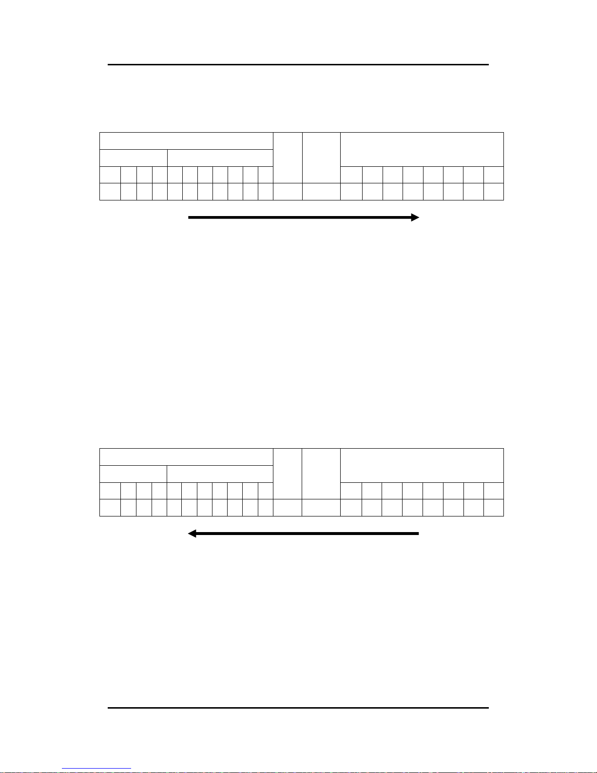
I-7231D CANopen/DCON Gateway user manual (ver. 1.04, Dec/14/2010) ------92
Step 1. In order to inform the I-7231D that the value of the object entry with
index 0x1400 and sub-index 02 will be modified by using the SDO Block
Download method, the Initiate SDO Block Download protocol is implemented.
11-bit COB-ID (bit)
Func Code Node ID
8-byte Data (byte)
10 9 8 7 6 5 4 3 2 1 0
RTR
Data
Length
0 1 2 3 4 5 6 7
1 1 0 0 0 0 0 0 0 0 1 0 8 C0 00 14 02 00 00 00 00
SDO client
SDO server
(I-7231D)
ccs
: 6
cc
: 0
s
: 0
cs
: 0
m
: 00 14 02
size
: 0
Because the value of s is 0, the size is not used.
Step 2. The I-7231D responds to the message by using the Initiate SDO Block
Download protocol. Afterwards, the SDO client can start to download the
object‘s data with index 0x1400 and sub-index 02 to I-7231D.
11-bit COB-ID (bit)
Func Code Node ID
8-byte Data (byte)
10 9 8 7 6 5 4 3 2 1 0
RTR
Data
Length
0 1 2 3 4 5 6 7
1 0 1 1 0 0 0 0 0 0 1 0 8 A0 00 14 02 7F 00 00 00
SDO client
SDO server
(I-7231D)
scs
: 5
sc
: 0
s
: 0
ss
: 0
m
: 00 14 02
blksize
: 7F
Page 93
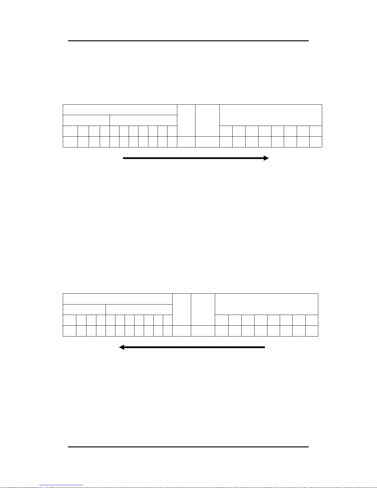
I-7231D CANopen/DCON Gateway user manual (ver. 1.04, Dec/14/2010) ------93
Step 3. The SDO client starts to transmit the data of the object entry index
0x1400 and sub-index 02 by using the Download SDO Block Segment protocol.
Seeing as the data length of the value is less than the maximum data length of
one block, the SDO Block Segment Download protocol is only implemented
once.
11-bit COB-ID (bit)
Func Code Node ID
8-byte Data (byte)
10 9 8 7 6 5 4 3 2 1 0
RTR
Data
Length
0 1 2 3 4 5 6 7
1 1 0 0 0 0 0 0 0 0 1 0 8 81 05 00 00 00 00 00 00
SDO client
SDO server
(I-7231D)
c
: 1
seqno
: 1
seg-data
: 05
Step 4. The I-7231D responds to the message to confirm if the transmission is
successful or not. If not, this block needs to be transmitted again. After
finishing the data transmission, the Download SDO Block Segment protocol is
terminated.
11-bit COB-ID (bit)
Func Code Node ID
8-byte Data (byte)
10 9 8 7 6 5 4 3 2 1 0
RTR
Data
Length
0 1 2 3 4 5 6 7
1 0 1 1 0 0 0 0 0 0 1 0 8 A2 01 7F 00 00 00 00 00
SDO client
SDO server
(I-7231D)
scs
: 5
ss
: 2
ackseq
: 01
blksize
: 7F
Page 94
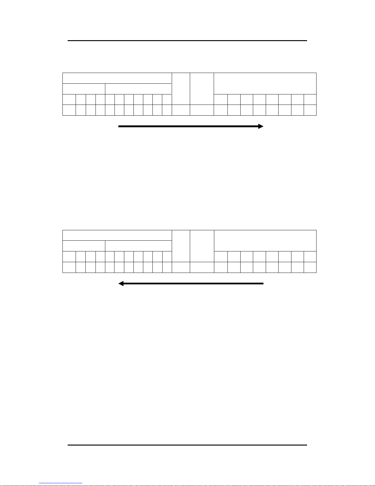
I-7231D CANopen/DCON Gateway user manual (ver. 1.04, Dec/14/2010) ------94
Step 5. The SDO client sends the ending message to finish the SDO Block
Download.
11-bit COB-ID (bit)
Func Code Node ID
8-byte Data (byte)
10 9 8 7 6 5 4 3 2 1 0
RTR
Data
Length
0 1 2 3 4 5 6 7
1 1 0 0 0 0 0 0 0 0 1 0 8 D5 00 00 00 00 00 00 00
SDO client
SDO server
(I-7231D)
ccs
: 6
n
: 5
cs
: 1
crc
: 00 00
Step 6. The I-7231D responds to the message to terminate the End SDO Block
Download protocol.
11-bit COB-ID (bit)
Func Code Node ID
8-byte Data (byte)
10 9 8 7 6 5 4 3 2 1 0
RTR
Data
Length
0 1 2 3 4 5 6 7
1 0 1 1 0 0 0 0 0 0 1 0 8 A1 00 00 00 00 00 00 00
SDO client
SDO server
(I-7231D)
scs
: 5
ss
: 1
Page 95
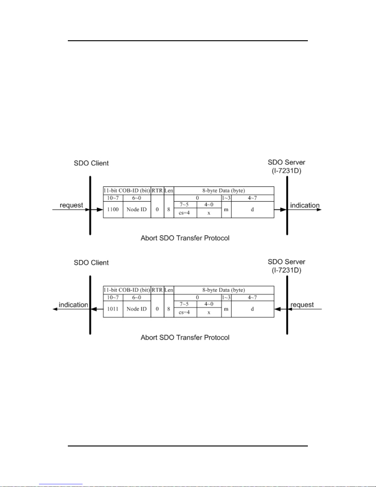
I-7231D CANopen/DCON Gateway user manual (ver. 1.04, Dec/14/2010) ------95
5.1.5 Abort SDO Transfer Protocol
In some situations, the SDO client or SDO server needs to terminate the
SDO transmission. For example, the value of entries which users want to
modify does not exist or is read-only, or users wouldn’t like to continue with the
uncompleted SDO protocol under some special conditions. When these
situations occur, both the client and the server can be activated to send the
Abort SDO Transfer message. The Abort SDO Transfer protocol is shown
below.
cs
: command specifier
4: abort transfer request
x
: not used, always 0
m
: multiplexer
It represents index and sub-index of the SDO
d
: contains a 4-byte “Abort Code” about the reason for the abort
Page 96

I-7231D CANopen/DCON Gateway user manual (ver. 1.04, Dec/14/2010) ------96
Abort Code Description
0503 0000h Toggle bit not alternated.
0504 0000h SDO protocol timed out.
0504 0001h Client/server command specifier not valid or unknown.
0504 0002h Invalid block size (block mode only).
0504 0003h Invalid sequence number (block mode only).
0504 0004h CRC error (block mode only).
0504 0005h Out of memory.
0601 0000h Unsupported access to an object.
0601 0001h Attempt to read a write only object.
0601 0002h Attempt to write a read only object.
0602 0000h Object does not exist in the object dictionary.
0604 0041h Object cannot be mapped to the PDO.
0604 0042h
The number and length of the objects to be mapped would exceed
PDO length.
0604 0043h General parameter incompatibility reason.
0604 0047h General internal incompatibility in the device.
0606 0000h Access failed due to an hardware error.
0607 0010h
Data type does not match, length of service parameter does not
match
0607 0012h Data type does not match, length of service parameter too high
0607 0013h Data type does not match, length of service parameter too low
0609 0011h Sub-index does not exist.
0609 0030h Value range of parameter exceeded (only for write access).
0609 0031h Value of parameter written too high.
0609 0032h Value of parameter written too low.
0609 0036h Maximum value is less than minimum value.
0800 0000h General error.
0800 0020h Data cannot be transferred or stored to the application.
0800 0021h
Data cannot be transferred or stored to the application because of
local control.
0800 0022h
Data cannot be transferred or stored to the application because of
the present device state.
0800 0023h
Object dictionary dynamic generation fails or no object
dictionary is present (e.g. object dictionary is generated
from file and generation fails because of an file error).
Page 97
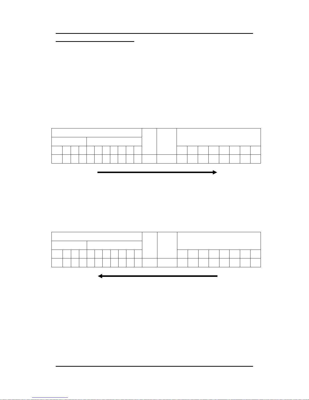
I-7231D CANopen/DCON Gateway user manual (ver. 1.04, Dec/14/2010) ------97
Abort SDO Transfer Example
The object index 0x1008 doesn’t have the sub-index 01 entry. Therefore, if
users read the object entry with index 0x1008 and sub-index 01, the I-7231D
will response the Abort SDO Transfer message. We will also use this point as a
demo to follow.
Step 1. Send the Rx SDO message to the I-7231D to obtain the object entry
with index 0x1008 and sub-index 01. Assume that the node ID for the I-7231D
is set to 1.
11-bit COB-ID (bit)
Func Code Node ID
8-byte Data (byte)
10 9 8 7 6 5 4 3 2 1 0
RTR
Data
Length
0123 4 5 67
1 1 0 0 0 0 0 0 0 0 1 0 8 40 08 10 01 00 00 00 00
SDO client
SDO server
(I-7231D)
ccs
: 2
m
: 08 10 01
Step 2. The I-7231D will respond to the Abort SDO message as its indication.
11-bit COB-ID (bit)
Func Code Node ID
8-byte Data (byte)
10 9 8 7 6 5 4 3 2 1 0
RTR
Data
Length
0 1 2 3 4 5 6 7
1 0 1 1 0 0 0 0 0 0 1 0 8 80 08 10 01 11 00 09 06
SDO client
SDO server
(I-7231D)
cs
: 4
m
: 08 10 01
d
: 11 00 09 06
Because low byte needs to transfer firstly, the data are “06 09 00
11” after converting. Therefore, after searching the Abort Code
table described above, this Abort Code can be interpreted as
“Sub-index does not exist”.
Page 98

I-7231D CANopen/DCON Gateway user manual (ver. 1.04, Dec/14/2010) ------98
5.2 PDO Communication Set
5.2.1 PDO COB-ID Parameters
Before using the PDO to transmit the real-time data, it is necessary to
check the COB-ID parameter of this PDO in the PDO communication objects.
This parameter determines the COB-ID of the PDO communication. It has 32
bits, and the meaning of each bit is given in the table follow.
Bit Number Value Meaning
31 (MSB) 0 PDO exits (PDO is valid)
1 PDO does not exist (PDO is not valid)
30 0 RTR allowed on this PDO
1 No RTR allowed on this PDO
29 0 11-bit ID (CAN 2.0A)
1 29-bit ID (CAN 2.0B)
28-11 0 If bit 29=0
x If bit 29=1: 28-11 bits of 29-bit COB-ID
10-0 (LSB) x 10-0 bits of COB-ID
Note: I-7231D only supports CAN 2.0A.
Page 99

I-7231D CANopen/DCON Gateway user manual (ver. 1.04, Dec/14/2010) ------99
In the following table, the default PDO COB-ID parameters are
presented.
Default COB-ID of PDO
Number of PDO
Bit10~Bit7
(Function Code)
Bit6~Bit0
TxPDO1 0011 Node ID
TxPDO2 0101 Node ID
TxPDO3 0111 Node ID
TxPDO4 1001 Node ID
RxPDO1 0100 Node ID
RxPDO2 0110 Node ID
RxPDO3 1000 Node ID
RxPDO4 1010 Node ID
Note: 1. Users can also define the PDO COB-ID by themselves. Actually, all
of the COB-ID can be defined by users except the reserved COB-ID
described in the table in section 3.1. When users want to define the
COB-ID, it is important to avoid the conflict with the COB-ID used in
the same node.
2. The PDO COB-ID parameters cannot be changed if the PDO is valid
(bit 31 =0).
Page 100

I-7231D CANopen/DCON Gateway user manual (ver. 1.04, Dec/14/2010) ------100
5.2.2 Transmission Type
The transmission type is one of several parameters defined in PDO
communication objects with sub-index 02. Each PDO has its own transmission
type. The transmission type indicates the transmission/reception character for
its corresponding PDO. The following table describes the relationship between
the value of the transmission type and the PDO character. For example, if
users used transmission type 0 for 1st TxPDO, the CANopen device will follow
the rule of the acyclic and synchronous PDO transmission.
PDO Transmission method
Transmission
Type
cyclic acyclic synchronous asynchronous
RTR
only
0
O O
1-240
O
O
241-251
-------------------------reversed-------------------------
252
O
O
253
O O
254
O
255
O
Note: 1. Transmission type 1-240 indicates how many SYNC objects the
TxPDO will be triggered by. The RxPDO is always triggered by the
following SYNC upon reception of data independent of the
transmission types 0-240.
2. Transmission type 252 and 253 are only used for TxPDO.
Transmission type 252 means that the data is updated (but not sent)
immediately after reception of the SYNC object. The PDO is only
transmitted on remote transmission requests for these two
transmission types.
3. For the transmission types 254 and 255, the event timer can be used
in the TxPDO. The PDO, which includes the DI value, will be sent
when the DI value is changed. For the RxPDO, both of these two
types mean that receiving the RxPDO will directly trigger an update
of the mapped data.
 Loading...