

IpCAS ipEther232, ipEther232.Telnet, ipEther232.Modem, ipEther232.PPP, ipNTP User Manual
...Page 1

ipEther product family
ipEther232 ipEther232.Telnet
ipEther232.Modem ipEther232.PPP
ipNTP ipEther232.IO
User guide
ipcas Gm bH
Telefon: +49 9131 7677 0
Telefax: +49 9131 7677 78
Internet:
http://www.ipcas.com
Wetterkreuz 17
D-91058 Erlangen
E-Mail: info@ipcas.de
Page 2

Contents Page
Chapter 1: Introduction...................................................... 5
1.0 Legal Information ..............................................................................................5
1.1 Registered Trademarks.....................................................................................5
1.2 Important Information........................................................................................5
1.3 Safety references..............................................................................................6
1.4 non-warranty .....................................................................................................6
Chapter 2: The Device....................................................... 8
2.1 Sockets .............................................................................................................8
2.2 Usage ipEther232 (virtual ComPort) ...............................................................10
2.3 Usage ipEther232.Telnet ................................................................................11
2.4 Usage ipEther232.Modem (Ethernet modem).................................................12
2.5 Usage ipEther232.PPP (PPP – Gateway).......................................................14
2.6 Usage ipNTP (SNTP Timeserver)...................................................................16
2.7 Usage ipEther232.IO (Datalogger).................................................................. 18
Chapter 3: Commissioning............................................ 20
3.1 Installation.......................................................................................................20
3.2 Configurationtool.............................................................................................21
3.3 Logfiles............................................................................................................25
3.4 Services ..........................................................................................................28
Chapter 4: Configuration of ipEther232..................... 31
4.1 Configuration of ipEther232 ............................................................................31
4.2 Checking the adjusted Com-Ports ..................................................................39
4.3 Parameter (Transparent UDP Mode) ..............................................................40
4.4 Kommunikationsdiagramm (Transparent UDP Mode) ....................................41
4.5 Sample for ipEther232 (Transparent UDP Mode) ...........................................42
4.6 Technical details for ipEther232......................................................................43
Chapter 5: Configuration of ipEther232.Telnet........ 46
5.1 Configuration of ipEther232.Telnet .................................................................46
5.2 Connection Test to ipEther232.Telnet.............................................................46
5.3 The Commando-Port.......................................................................................46
5.4 Parameter .......................................................................................................47
Änderungen vorbehalten Stand 09.09.05
ipcas GmbH ipEther232 V11.01 Seite 2 von 150
Page 3

5.5 Datacommunication .......................................................................................49
5.6 The Datencommunication (Gateway - Modus)................................................50
5.7 Sample der ipEther232.Telnet Schnittstelle ....................................................51
5.8 diagram of communication ..............................................................................52
5.9 Technical details for ipEther232.Telnet ........................................................... 53
Chapter 6: Configuration of ipEther232.Modem...... 55
6.1 Configuration of ipEther232.Modem ...............................................................55
6.2 Serial Configuration.........................................................................................61
6.3 Configure Password Protection (Serial Devices only) ..................................... 61
6.4 ipEtherModem.inf (Driver-File) .......................................................................63
6.4 ipEtherModem.inf (Driver-File) .......................................................................63
6.5 Control Commands .........................................................................................66
6.6 AT Command Input and Execution .................................................................66
6.7 Transmission Mode......................................................................................... 66
6.8 Quick Reference for AT Commands and Registers ........................................67
6.9 Description of the AT Commands ...................................................................68
6.10 Overview of the registers ..............................................................................71
6.11 Result Code ..................................................................................................78
6.12 Technical details for ipEther232.Modem ....................................................... 79
Chapter 7: Configuration of ipEther232.PPP............ 81
7.1 Configuration of ipEther232.PPP ....................................................................81
7.2 Configuration samples ....................................................................................86
7.3 Logfile .............................................................................................................92
7.4 Technical details for ipEther232.PPP..............................................................94
Chapter 8: Configuration of ipNTP ............................... 96
8.1 Configuration of ipNTP....................................................................................96
8.2 SNTP-Clients ................................................................................................ 101
8.3 DCF77-Antenna and DB9 Clutch ..................................................................106
8.4 GPS-Antenna and DB9 Clutch......................................................................106
8.5 Technical details for ipNTP ...........................................................................107
Kapitel 9: Configuration of ipEther232.IO ......................... 109
9.1 Configuration of ipEther232.IO......................................................................109
9.2 Parameter .....................................................................................................112
Änderungen vorbehalten Stand 09.09.05
ipcas GmbH ipEther232 V11.01 Seite 3 von 150
Page 4

9.3 Explanation of the function parameter...........................................................114
9.4 Diagram of Communication...........................................................................116
9.5 Data Message Format...................................................................................117
9.6 Samples for ipEther232.IO............................................................................119
9.7 OPC-Server ..................................................................................................125
9.8 Technische Details für ipEther232.IO............................................................127
Chapter 10: General technical details ....................... 130
10.1 Technical Data ............................................................................................130
10.2 Pin all ..........................................................................................................131
10.3 RS232 Connection Cable............................................................................133
10.4 Pin allocation for ipEther232.Modem OEM .................................................135
10.5 Power supply modules ................................................................................137
10.6 RS232 Module ............................................................................................ 138
10.7 RS232.Modem Module ...............................................................................138
10.8 RS485 Module ............................................................................................ 139
10.9 RS485 as a 2 wire solution .........................................................................140
10.10 DCF77 Modul............................................................................................140
10.11 GPS / DCF77 Modul .................................................................................140
10.12 I/O Modul 6x Input.....................................................................................141
9.10 DCF77 Modul..............................................................................................142
9.11 GPS / DCF77 Modul ...................................................................................142
10.13 Dimensions ............................................................................................... 142
10.14 Statement of EEC Compliance .................................................................145
10.12 FAQ’s ........................................................................................................146
10.15 Glossar......................................................................................................150
Änderungen vorbehalten Stand 09.09.05
ipcas GmbH ipEther232 V11.01 Seite 4 von 150
Page 5

Chapter 1: Introduction
1.0 Legal Information
COPYRIGHT © 2004 ipcas GmbH
All rights reserved. No part of this document may be copied out, copied, reproduced, or
transferred in other form without the previous express written approval of the ipcas GmbH.
Misprint, mistakes and changes are left.
In so far as legally as possible, we cannot accept any liability for consequential damage caused
by using this guide. In other respects we shall accept liability for intention and gross negligence
only.
We have done our utmost to ensure that the information in this user guide is complete, accurate
and up to date. We don’t give any warranty for the correctness of the made details or for the
applicability of the decribed Product for any special purpose. We cannot provide any warranty
that changes to third-party equipment referred to in this guide will have no effect on the
applicability of the information provided in this guide.
The author reserves all rights, including the right to reproduce this guide in full or part thereof in
any form whatsoever.
The content is subject to change without prior notification.
The product is subject to technical change without prior notification.
1.1 Registered Trademarks
All in this Document used Trade marks are stated for identification purposes and may be the
property of the various holders.
1.2 Important Information
Please, pay attention to electrostatic unloadings. Use a work station suitable for the work with
CMOS components. Before you consult the customer service of your supplier, you should
notice the notes in this manual. During the warranty period, resorting to the customer service
may incur costs, if the fault or problem was caused by the customer and the solution or remedy
is described in this guide.To clean the device just use dry cloth. Dont use liquid- or
Aerosolcleaner.
Removing the serial number will void the warranty rights.
Damage caused by inappropriate packing will not be borne by the forwarding agent / insurance
company.
Änderungen vorbehalten Stand 09.09.05
ipcas GmbH ipEther232 V11.01 Seite 5 von 150
Page 6

1.3 Safety references
As is the case with all electrical equipment there are some basic safety precautions that you
should apply. These safety precautions are primarily for your safety but also to prevent damage
to the device.
Settings not described in this guide and changes to the device electronics are to be carried out
by an authorized vendor only.
Read the user guide carefully and keep it to hand.
Make sure that the device is placed on a stable, flat surface. Make sure that for rail mounted
devices the top hat rail is sufficiently grounded and the rail spring has good contact.
Use the Device at a tempered, dust- and vibrationfree Place.
Excessive heat will damage the Device. Therefore it should not suspended to high
Temperatures. (No mounting near heatsources. No direct sunlight.)
Device shouldn’t be used at exceptional humidity.
Make sure no Liquids or Particles can get into the Device.
Dont place the Device near to magnetic fields, because this can be responsible for data loss.
(Never make any changes to the device that are not described in the user guide.)It´s forbidden
to run the Device with an other supply voltage which isn’t described for the Device. This could
damage the device and you will have to pay for the repairs. Only the authorized vendor may
change the input voltage, should this become necessary.
The powersupply must be free from overloads and other malfunction. The Interfaces must be
free from overloads, different potential and other malfunction. Otherwise the Deivce could
become damaged.
Don’t carry out any modifications in the Device, which are not described in this user guidel. That
could damage the Device and the owner will be liable to pay the costs.
Make sure that the following conditions are fulfilled:
Use a suitable power supply unit. In case of doubt consult your supplier. The device should be
used exclusively with the mains unit supplied. Using a different power supply unit may lead to
the device being damaged.
If the device is damaged, disconnect from the mains. Arrange for immediate repair.
Make sure the mains socket is located near the device and is easily accessible.
You have to pull the mains plug completely to disconnect.
Make sure the maximum power rating of an extension cable or multiple contact plug, if used,
must not be exceeded. The mains cable must be protected against damage by yourself. Do not
place anything on the cable and put it down, so that there is no danger of stepping on or
tripping over it.
A damaged mains cable must be replaced immediately.
Make sure the mains cable is disconnected before starting to clean the device. Use a dry cloth
only. Do not use any liquid or aerosol cleaning agent.
1.4 non-warranty
The ipcas GmbH is not liable for the use of Software or Products which are mentioned in this
Document.
Also this company is not liable if use of these products hurt any existing or future licence or
patent laws from third party. ipcas GmbH reserves the right to execute modifications of the
contents without previous announcements.
Änderungen vorbehalten Stand 09.09.05
ipcas GmbH ipEther232 V11.01 Seite 6 von 150
Page 7

1.5 limited warranty
The ipcas GmbH guaranteeing the final consumer (purchaser), that the Device at proper use
will have a 24 month long period of time without any material damage or through that caused
working capacity. At incorrect work or damaged material, the Ipcas GmbH will
repair or change parts of the product or the whole Product respectively everything
within the warranty period, that seems to be necessary for the Ipcas GmbH to get back
the normal operating status, if the bill is available. In free discretion of the Ipcas GmbH, the
exchange may contain new or as good as new Devices or Parts, wich have the same
functionality like the original Device.
This warranty will expire instantly, if the Device is modifiyed, used uncorrect,
sportive or careless damaged through force majeure, or using the Device out the proper
working conditions.
Only the purchaser have claim for repair or exchange. Other pretensions aren’t existing. These
warranty conditions substitute all other warrantys or warranty services, no matter if assertive,
explicit or implicit, and they don't mean, that the product came out for certain or economic
intention or any other intention.
Not at all and in no way the ipcas GmbH is liable for indirekt or any damage or
consequential damage wich the customer eventually suffer.
The Ipcas Gmbh don't gives any warranty that the Software / Hardware match your
requirements, or that the Software / Hardware work accurate and faultless. With the
installation of the Software / Hardware you take the responsibilty for the use of the
software / Hardware, also your expected Results, the installation, the application and the
achieved results wich were made through the use of the software.
For claiming your warranty service, please get to your Vendor, who will send back the Device to
the Ipcas GmbH. If there's no bill with the Device or if the whole thing isnt in the Warranty
period anymore, Ipcas will repair or change the damaged parts (own choice) and will charge the
parts and the working time. Repaired or replacement Devices will be sent back to the added
address.
CAUTION:
Product warranty will be void if the serial is removed.
Through unsuitable packing caused damage wount be overtaken by
the carrier / insurer.
Änderungen vorbehalten Stand 09.09.05
ipcas GmbH ipEther232 V11.01 Seite 7 von 150
Page 8
Chapter 2: The Device
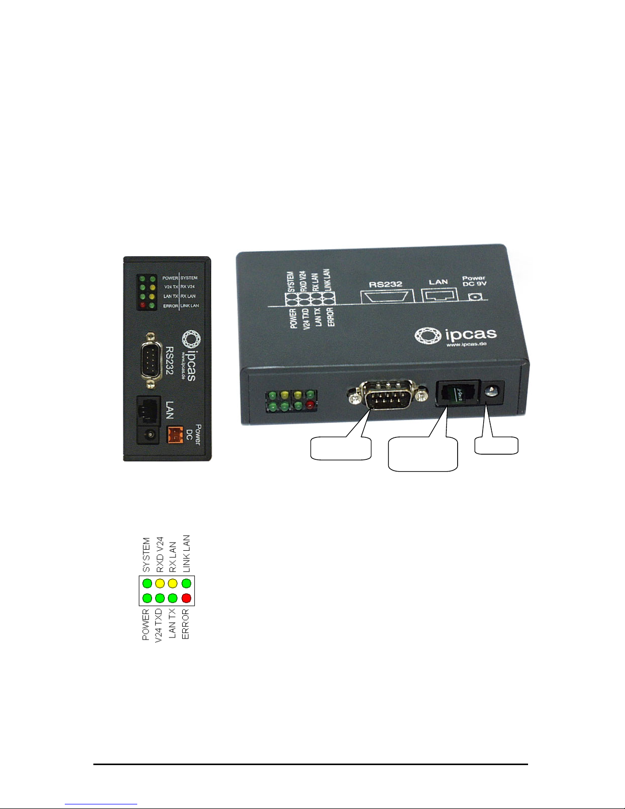
2.1 Sockets
ipEther232 has three sockets:
• Ethernet (10BaseT) for a 10/100 Mbit network
• RS232 SUB-D 9
• 9V DC mains supply or 24 VDV or 48/60V DC
A diagram of all connectors and their designation is displayed on the housing.
behalten Stand 09.09.05
ipcas GmbH ipEther232 V11.01 Seite 8 von 150
The LEDs indicate the device state and have the following meaning:
• POWER The device is switched on.
• System Slow flashing indicates that at the moment there is
no connection to a PC. Fast flashing indicates that
the device is in use.
• LINK LAN There is a physical connection to the network.
• LAN Rx Packets are received by the Ethernet.
• x Packets are sent to the Ethernet.
• 24 Rx Data is received via the RS232 line.
• V24 Tx Data ia the RS232 line.
• Error An error has occured in the RS232 line.
At Ethernetprotocols like IPX, RIP and IGRP (MTU
p
he
Ehternetprotocol.
After the virtuel Com-Port is closed the red LED will
ake it optically visible.
LAN T
V
is sent v
RS232
SUB-D 9 Pin
Ethernet
10/100
RJ45
9V DC
higher then 1500) the red LED lights u
because it can’t be recognized by t
light up for 0.5 seconds to m
Änderungen vor
Page 9
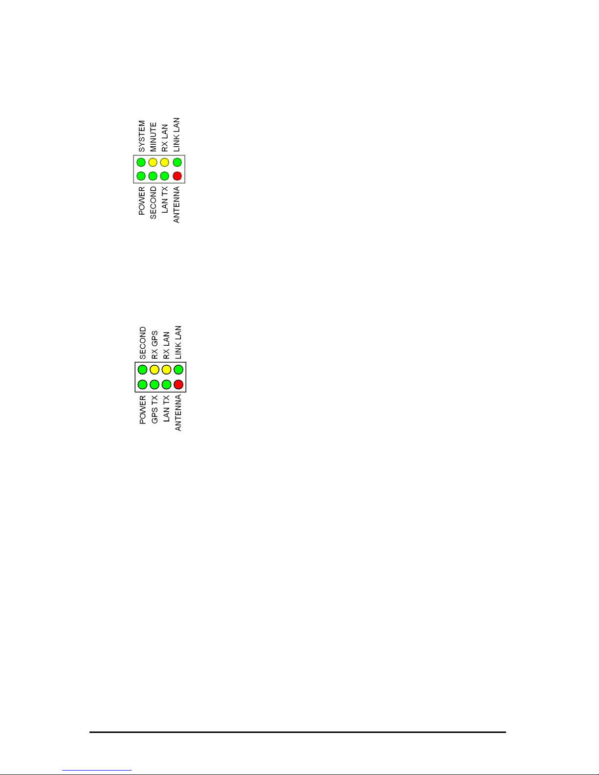
Exception ipNTP, here the LEDs have the following
meaning including Version 10.9:
moment there is
cates that the
AN ork.
• LAN Rx ackets are received by the Ethernet.
• LAN Tx
• SECOND 7.
• MINUTE -77.
• ANTENNA
For the ipNTP ex version 10.10 with DCF and GPS realization the LEDs have the
following signification:
• POWER The Device is switched on.
• SECOND
(1) Second impulses received by the DCF-77.
• GPS RX
(2) Packets are received by the GPS.
• GPS TX
(2) Packets are sent to the GPS.
• LAN RX Packets are received by the Ethernet.
• LAN TX Packets are sent to the Ethernet.
• LINK LAN There is a physical connection to the network.
• ANTENNA If the LED is durable glowing it means that no
DCF77or GPS-Signal is received. If the LED is flashing
it means no optimal Transmission is established and
that’s why it can’t be synchronized.
(1) Only for ipNTP with DCF-77-Antenna
(2) Only for ipNTP with GPS-Antenna
• POWER The device is switched on.
• System Slow flashing indicates that at the
no synchronisation. Fast flashing indi
device is in use.
• LINK L There is a physical connection to the netw
P
Packets are sent to the Ethernet.
Second impulse is received by the DCF-7
Minute impulse is received by the DCF
DCF-77 signal is lost.
Änderungen vorbehalten Stand 09.09.05
ipcas GmbH ipEther232 V11.01 Seite 9 von 150
Page 10
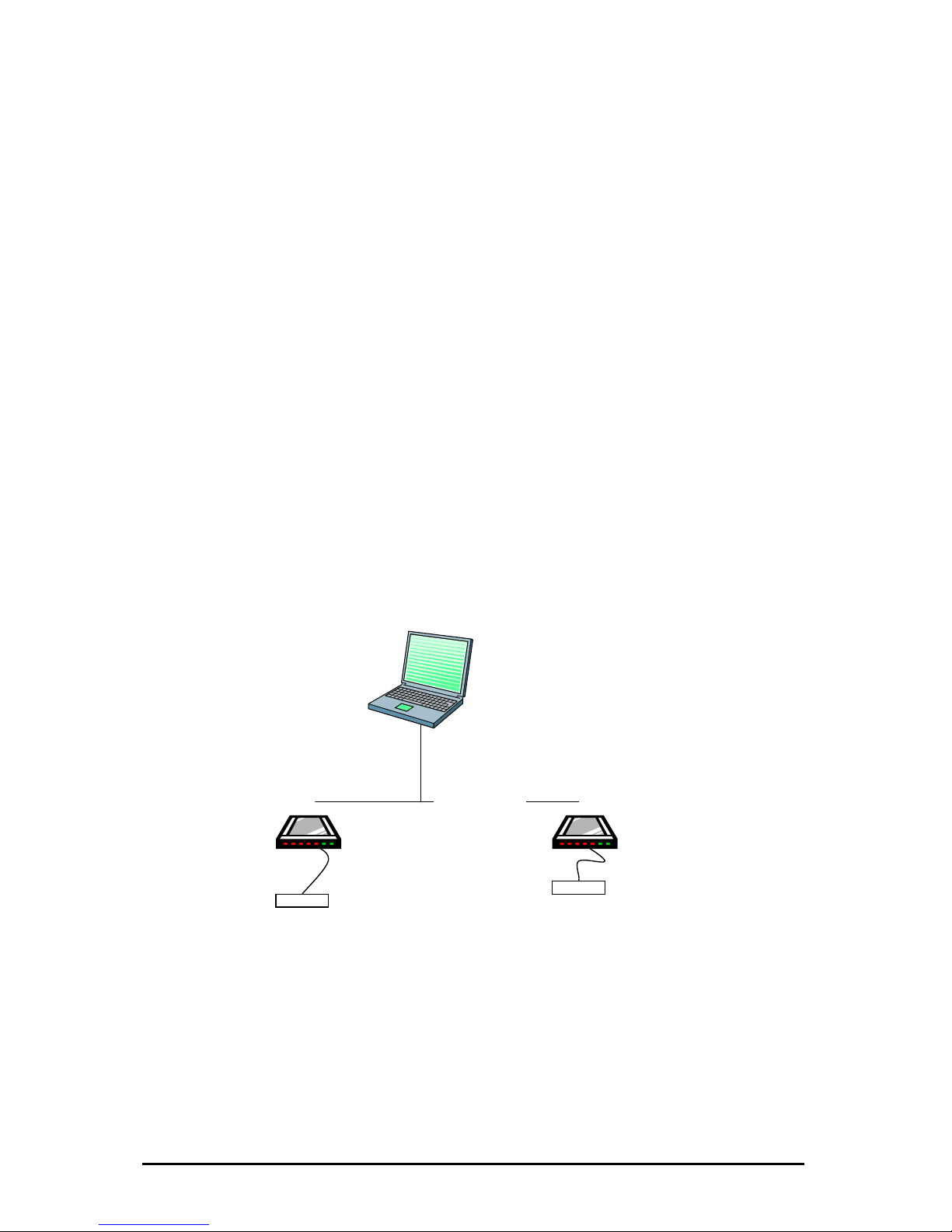
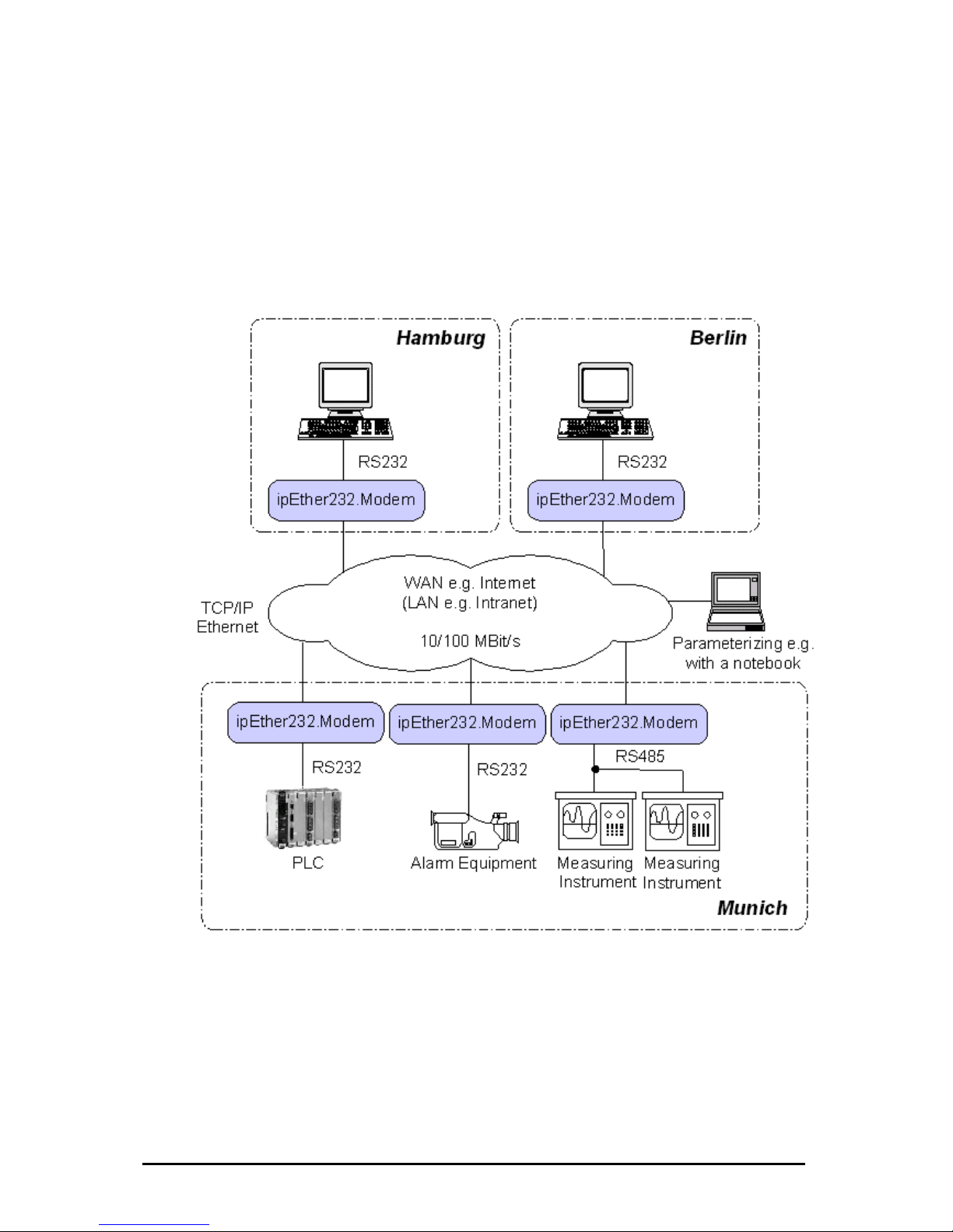
2.2 Usage ipEther232 (virtual ComPort)
ipEther2 u
WAN.
This allo trol de ng
distance
Such de e
• modems
• printers
• SPS controls
•
tegration in the Windows environment is realized via a driver which supplies a
irtual serial "COM" interface.
For the p virtue integrated normal
interface in the pc. Also the as
possible e es can be
installed
32 enables you to s via a TCP/IP network, LAN or se serial interface
ws you to con vices without a network interface over lo
s.
vic s are:
embedded controllers
In
v
ap lication the ll COM-Interface looks like a
Behavior of the Interface corresponds as far
lik a physical COM interface. Up to 255 virtual interfac
at one PC.
COM2
COM3
ethernet/TCP/IP
Änderungen vorbehalten Stand 09.09.05
ipcas GmbH ipEther232 V11.01 Seite 10 von 150
Page 11
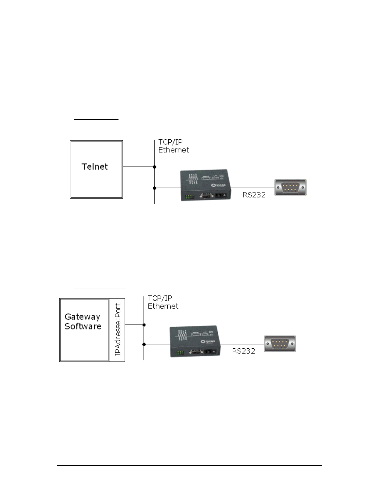
2.3 Usage ipEther232.Telnet
The RS232/485-Ethernet-Converter, ipEther232.Telnet makes it possible to control devices with
RS232/485 in rfaces via TCP/IP (Ethernet).
From several workstations to the network all attached devices can be used. There are two
supported mo
Mode 1: Tel
te
des supported by this device: telnet and gateway.
net
ices!
The Telnet-connection gives you high measurey of flexibility and the control about
the Ethernet connected serial Devices and beyond that it’s a Operating system-independently.
No drivers are needed because nearly every operating system has telnet pre-installed.
Mode 2: Ga ay
et to serial Dev
Telnet from Ethern
tew
Gateway from serial Devices / Data to Ethernet!
The Gateway functionality gives you the possibility for direct data transfer to a TCP/IP Address
(IP-Address:Port).
For example an application can log, filter, analyze, format and represent serial Data
in the Internet / Intranet.
Änderungen vorbehalten Stand 09.09.05
ipcas GmbH ipEther232 V11.01 Seite 11 von 150
Page 12

2.4 Usage ipEther232.Modem (Ethernet modem)
ipEther232.Modem enables you to use serial interfaces via a TCP/IP network.
This allows you to control devices without a network interface over long
distances. In addition to the serial interface, the Ethernet modem also has a
network interface. In order to connect two serial devices simply use two modems
linked via Ethernet instead of a serial cable.
Ø terminals
Ø CNC controllers
Ø counting devices
Such devices are: Ø embedded controllers
Ø industrial switches
Ø serial printers
Thus all applications and devices that support terminal or modem functionalities
can also be used via the Ethernet. This has numerous advantages:
• lower telephone costs
• reduce the number of analog connections (monthly fee)
• simplified logistics
• extremely low porting costs
• protects your investments by converting serial devices into network
devices without necessitating changes in the existing software, saving
additional product development costs
• sing solutions
Ø SPS controllers
Ø card reader
Ø Measuring equipment
Ø UPSs
versatile power supply and optimal hou
•
• automatic setup of network connection after interruptions
• easy to setup and suitable for larger installations
ple integration of serial applications • sim
Änderungen vorbehalten Stand 09.09.05
ipcas GmbH ipEther232 V11.01 Seite 12 von 150
Page 13
"Networking" will soon be the global standard. However, manufacturers
require expensive labor, precious time and comprehensive experience to
develop network technologies. As most devices are already equipped with
an RS232/485 interface, the Ethernet modem offers an instant and efficient
solution for transmitting RS232/485 data via the network. The Ethernet
modem not only provides added value to your product, it also adds to the
val
ue of your existing equipment for the next generation.
Änderungen vorbehalten Stand 09.09.05
ipcas GmbH ipEther232 V11.01 Seite 13 von 150
Page 14
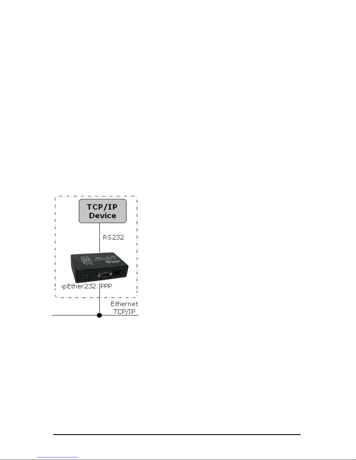
2.5 Usage ipEther232.PPP (PPP – Gateway)
kets via
).
With ipEther232.PPP all these (serial) devices can be linked up to an Ethernet
LAN via TCP/IP and thus also to the internet or your company intranet.
The PPP gateway solution works with all operating systems and is compatible
with existing PPP applications. You can start several services (ftp, telnet, www,
ssh, rsh, rcp etc.) simultaneously via this transparent network connection.
1.) „Ethernet for all“
Ethernet capability for all TCP/IP enabled devices without
a dedicated Ethernet interface, such
- Embedded PC
- SPS
- PC
- Notebook
- Modem
- Router
- Palm
The PPP / Ethernet – Converter enables the transmission of network pac
a serial interface from and to the Ethernet (PPP = Point to Point Protocol
Änderungen vorbehalten Stand 09.09.05
ipcas GmbH ipEther232 V11.01 Seite 14 von 150
Page 15
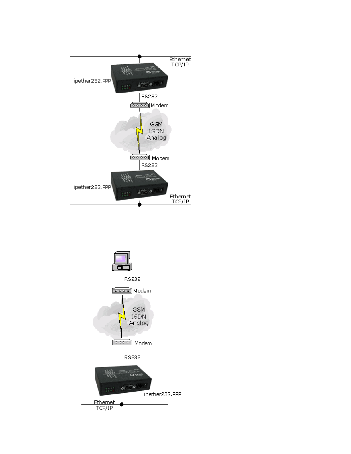
2.) „simple Network routing“
Änderungen vorbehalten Stand 09.09.05
ipcas GmbH ipEther232 V11.01 Seite 15 von 150
Simple routing between two
networks via GSM, ISDN or analog
modems, for instance to link up a
branch to the company LAN.
3.) „dial i
Einwählmöglichkeit für
Enables company LAN access for home
office, remote maintenance or for
company networks.
n“
Page 16
Änderungen vorbehalten Stand 09.09.05
ipcas GmbH ipEther232 V11.01 Seite 16 von 150
2.6 Usag ver)
The ipNTP Standalone Timeserver can transmit DCF77 / GPS time information
onto computers, controllers or other dynamically critical devices / applications
ove t client first determines the average transmission time for
the data exch time server. After that the client fetches the current
time and patches this value around the transmission time. The time on the client
deviates then only a few milliseconds from the timeserver.
All components in the TCP / IP network could be synchronized over the SNTP
protocol with the time signal transmitter Mainflingen near Frankfurt at the Main
(DCF77), or through the global satellite navigation system (GPS).
Time-precise solutions are needed in task executions, schedulers, personnel
information systems, time recordings and error logging. Through the commitment
TCP / IP is the platform independen
guaranteed.
DCF77 / GPS
antenna
e ipNTP (SNTP Timeser
ipNTP-TimeServer
time detection system
task execution
TCP/IP
Ethernet
SNTP-Protocol
r he ethernet. The
ange with the
of the network protocols SNTP (Simple Network Time Protocol – RFC 2030) and
ce even in heterogenous networks
Page 17

NTP Server - Information
The network time protocol (NTP) is used in order to synchronize the time of a
client over the Internet/Intranet with other computers or with an external clock.
The primary NTP timeservers are over external timers locked maximally exactly
to the Coordinated Universal Time (UTC). The NTP Client synchronize the time
with NTP commands with the servers indicated as an argument.
DCF77 - Information
The DCF77 radio clocks receive the official time of the federal republic of
Germany from the physical-technical federal institution (PTB) in Braunschweig
and transmit the signal over different interfaces to computers and systems. The
long-term accuracy of the PTB calibrating standard measure is achieved by radio
alignment of the sender DCF77 in Mainflingen at Frankfurt/Main of 1 x10 E-13
weekly. Due to the high accuracy only this time is recognized as legally binding in
the federal republic.
GPS - Information
000 km high satellites are moving in different orbits around the
arth. In every satellite is an atomic clock (min. accuracy 1x 10 E-12), whose time
sent out continuously with the orbital data. The GPS-receiver registers the
ates of minimum 3 ,maximum 6 satelites and calculates his position from
.
In approx. 20.
e
is
d
these values. If the position is computed, the terms of the dates can be
determined by the individual satellites. From these values the GPS world time is
determined in the timeserver and continued about a variable quartz time exactly
Änderungen vorbehalten Stand 09.09.05
ipcas GmbH ipEther232 V11.01 Seite 17 von 150
Page 18
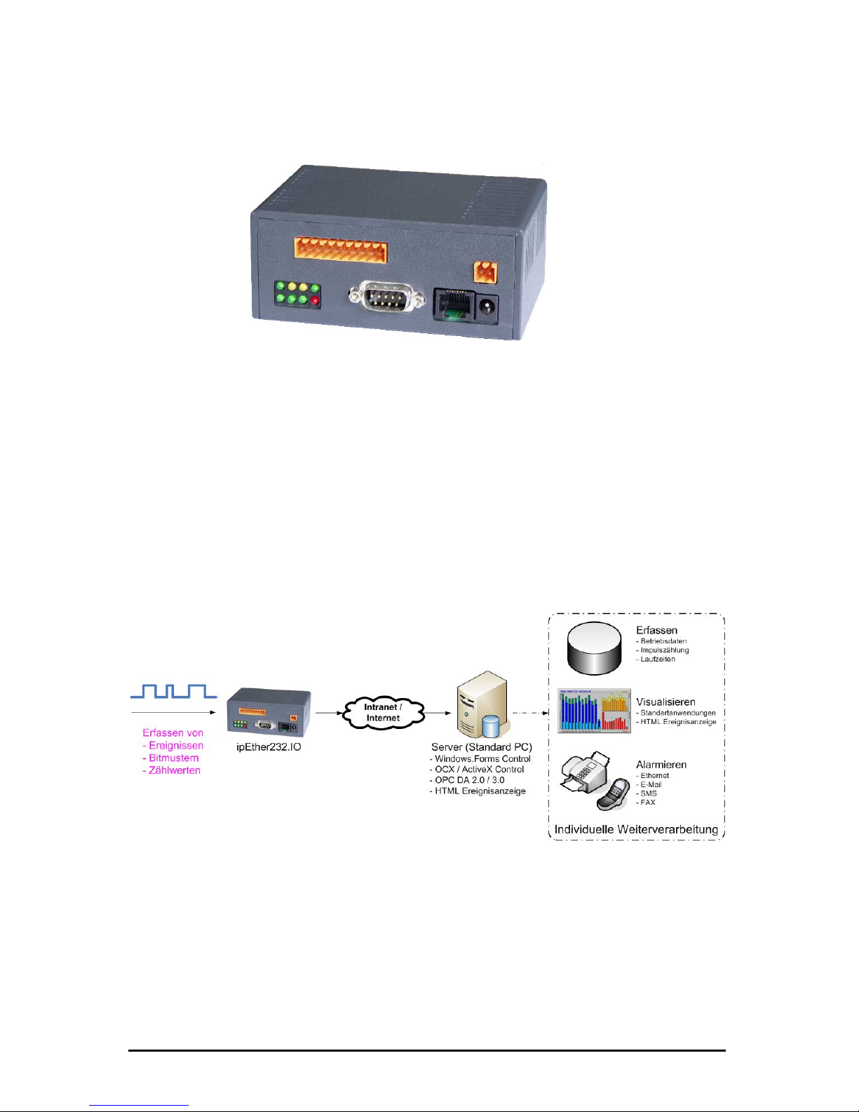
2.7 Usage ipEther232.IO (Datalogger)
he compact "ipEther232.IO" data logger / event logger enables acquisiton of
igital input values such as process and machine data which are then
utomatically transferred via Ethernet to a central server (standard PC) for further
rocessing.
Acq
T
d
a
p
uisition, counting, monitoring of digital signals
processing, visualization, warnings
Its modular structure and consistent separation allow easy implementation for a
ide range of uses. ipEther232.IO is highly scalable for small or high numbers of
O channels for central or decentral digital data acquisition wherever the data is
eeded.
Ether232.IO features a compact design, is easy to integrate and offers a wide
nge applications including process and machine data acquisition, automation,
entral building control systems, and measurement data acquisition.
w
I/
n
ip
ra
c
Änderungen vorbehalten Stand 09.09.05
ipcas GmbH ipEther232 V11.01 Seite 18 von 150
Page 19

Änderungen vorbehalten Stand 09.09.05
ipcas GmbH ipEther232 V11.01 Seite 19 von 150
Page 20

Chapter 3: Commissioning
3.1 Installation
Connect the device to the mains. The "Power“ signal and the flashing "System“
LED indicate that ipEther232 is ready for operation.
ipEther232 is connected to the network via an RJ45 socket.
The "Link LAN“ LED (connection) indicates the connection to the LAN.
If this is not the case, check the netwok connection or network line.
The enclosed CD contains a driver set-up program and the configuration tool.
The driver runs on all Windows NT based operating systems, therefore Windows
NT with SP5, Windows 2000 and Windows XP.
All Applications are based on the Microsoft .Net Framework 1.1. If .Net is not jet
installed on your Machine - just get and Install the DotNet framework 1.1.
Here is the URL:
http://msdn.microsoft.com/netframework/downloads/updates/default.aspx
(ca.23mb)
If you don't have an internet connection please install it from cd.
In addition the Datebase Application needs the "Microsoft Data Access
components 2.8" if this is not already installed on your Computer:
http://msdn.microsoft.com/data/mdac/downloads/default.aspx (ca.5mb)
If you don’t have installed this and you want or need it please look on our
driver cd.
No PC reboot is necessary after installation. The configuration tools starts
automatically after installation.
For later configuration sessions the program is included in the "Program files ipcas GmbH – ipEther Products“ folder.
Änderungen vorbehalten Stand 09.09.05
ipcas GmbH ipEther232 V11.01 Seite 20 von 150
Page 21
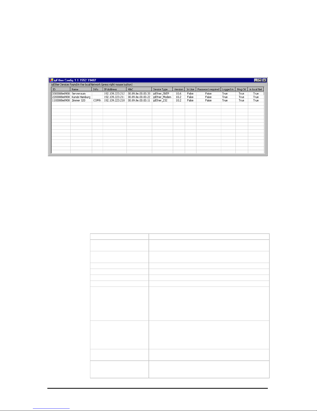
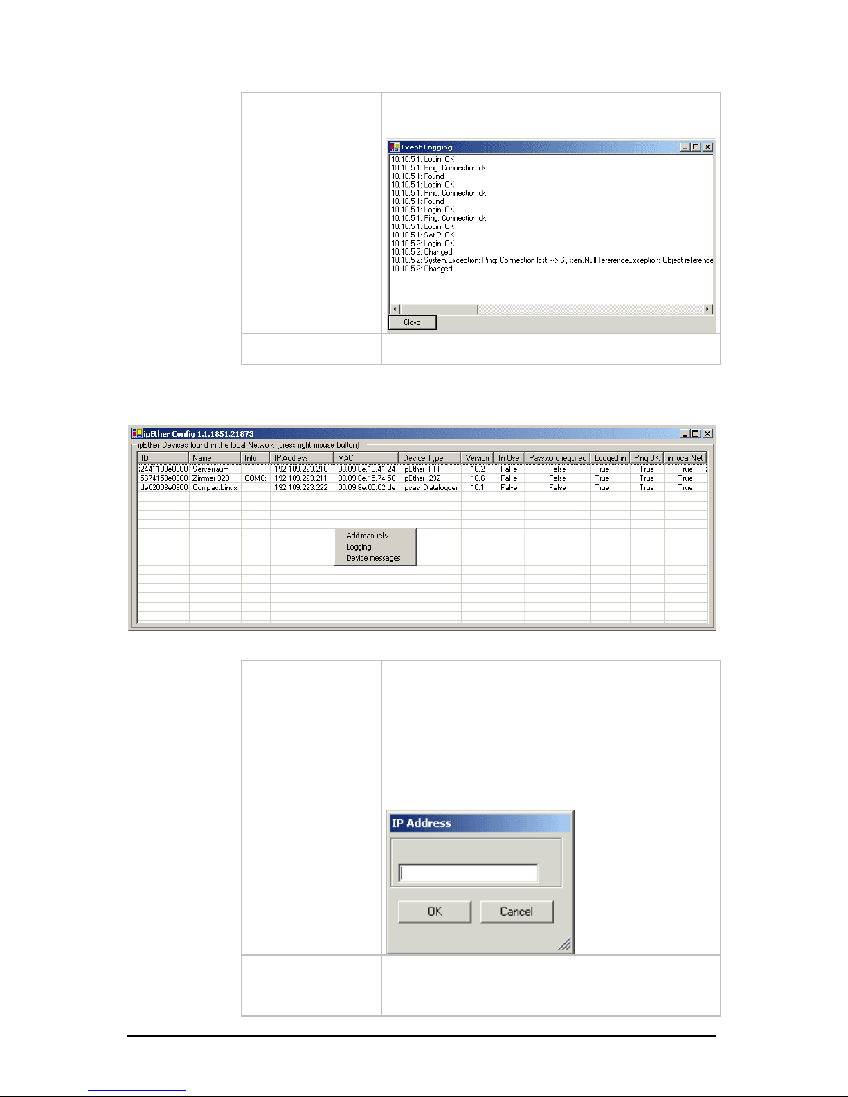
3.2 Configurationtool
The configuration program recognizes all devices in its own network segment,
even if they do not have a valid IP address.
By clicking on a column in t ddress”) all found
es are sorted for a be
order
he overview border (e.g.: “IP A
devic
tter overview.
In the overview b
are the following entries:
ID
Device-id
Name
Info (Comments could be very helpful to find a
particular device very quickly)
Info
Current configured ComPort (only at ipEther232
„virtual ComPort“)
IP Address
Current IP-Address
MAC
MAC-Address
Device Type
Firmwaretype of the device
Version
Current Firmwareversion
In Use
On ipNTP - DCF77
PS
m
On ipNTP - G
If this entry is „True“, the device is already in use and
you shouldn`t configure the parameters.
The device received data one minute along if this
entry is “True”
If this entry is “True”, the device received signals fro
several satellites.
Passwort required
If the password is forgotten, the device must be
returned.
If this entry is „True“, the device is passwordprotected and the password have to be entered
before the configuration. (Right-click “Login”)
ogged in
If this entry is „False“, the password (Right-click
tion.
L
„Login“) have to be entered before the configura
Ping OK
If this entry is „False“, the device couldn`t be found. It
is not connected, switched of or is in another network
segment.
Änderungen vorbehalten Stand 09.09.05
ipcas GmbH ipEther232 V11.01 Seite 21 von 150
Page 22
local Net
If this entry is „False“, the device is not in the local
network segment.
-
vents that a
device is getting inaccessible by mistake.
in
If the device is installed behind a router, the IP
Address couldn`t be changed. This pre
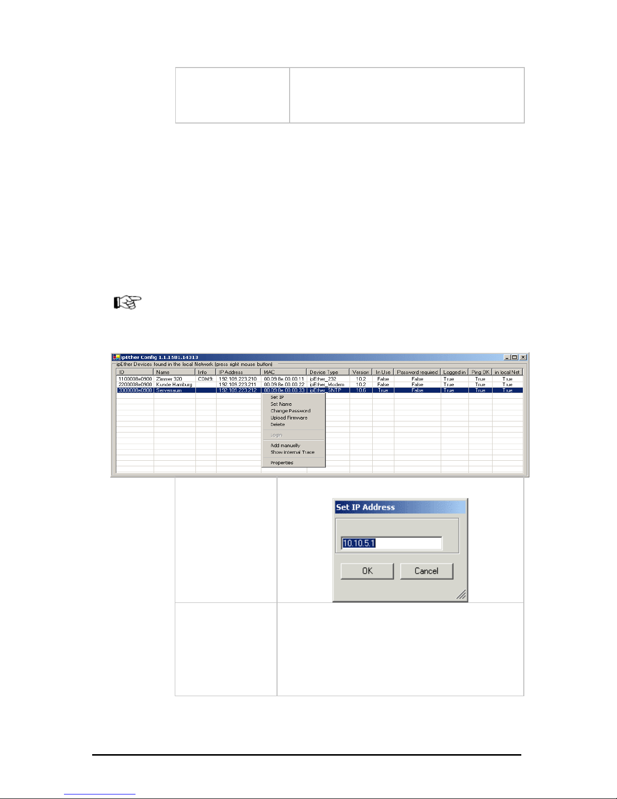
To start with, each device must be allocated an unambiguous IP address.
On delivery of ipEther232 no valid IP-Address has been set (Default: 10.10.5.1).
he IP-Address can be obtained from the network administrator. It must comply
ith your network and cannot be assigned twice.
-Address from your network administrator for your ipEther232.
In order to set the IP address in your ipEther232, the device must be connected
to its own network segment.
If need be, connect the device via a "cross over“ cable to the PC.
Durch einen Rechten Mausklick auf einen Geräteeintrag wird ein Dialog gezeigt
in dem Sie weitere Aktionen ausführen können.
T
w
If you are embedded in a DHCP network, you`ll have to recieve a static
IP
Set IP
Set IP-Address
Set Name
Set Name
Änderungen vorbehalten Stand 09.09.05
ipcas GmbH ipEther232 V11.01 Seite 22 von 150
Page 23
D
u
r
c
h
e
i
n
e
R
e
h
e
n
M
a
u
s
k
l
i
c
a
u
f
k
e
i
n
e
n
G
e
r
ä
t
e
e
i
n
t
g
w
i
r
d
n
c
t
k
r
a
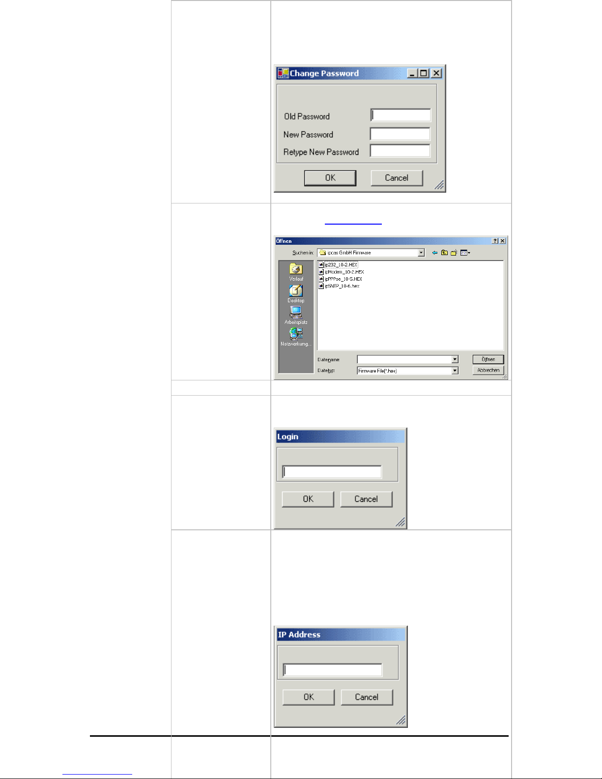
Change Password
Set / change password
Upload Firmware
Update new firmware. You can find new versions of the
firmware on
www.ipcas.de . You should only update if
you really need to.
Delete
Delete current marked entry
Login
If the device is password protected (Passwort required
„True“) you have to enter the password before the
configuration.
=
Ad
Änderungen vorbehalten Stand 09.09.05
ipcas GmbH ipEther232 V11.01 Seite 23 von 150
d Manually
ipEther232 is connected after a router, they are not
utomatically located. They have to be entered manually
Add Device manually“).This requires the entering of the
address. If the device can be accessed via this
ddress, it is included in the list.
the device is installed after a router, the IP address
couldn`t be changed, as otherwise the device might
become inaccessible by mistake.
If
a
("
IP
a
If
Page 24
Show internal Trace
Open current logfile. The messages will be showed from
the configurationtool.
Properties
Type-specific configuration surface.
Further informations in the respective chapters.
It will be opened a dialog by a right-click on no entry of device.
dd Manually
ipEther232 is connected after a router, they are not
utomatically located. They have to be entered manually
Add Device manually“).This requires the entering of the
the device is installed after a router, the IP address
couldn`t be changed, as otherwise the device might
become inaccessible by mistake.
A
If
a
("
IP address. If the device can be accessed via this
address, it is included in the list.
If
Änderungen vorbehalten Stand 09.09.05
ipcas GmbH ipEther232 V11.01 Seite 24 von 150
Page 25
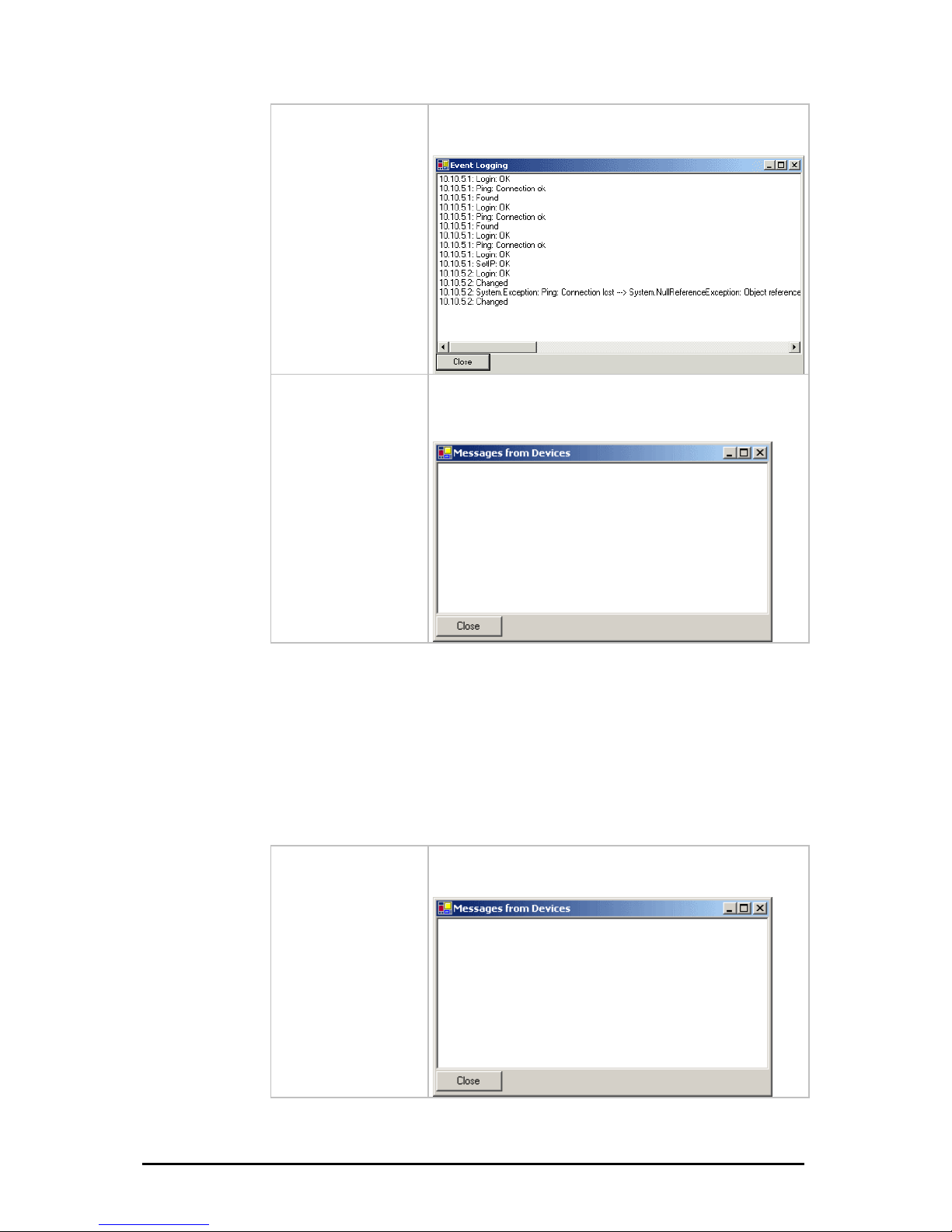
Logging
(Shinternal Trace)
Dispaly current Logfile.The messages will be showed
from the configurationtool.
Device messages
ctual Logfile. Messages from the device and
the firmware are shown here. The config tool must be
activated.
Retrieve a
3.3 Logfiles
e error description
nfigtool via ethernet.
ed in the Windows Event-Manager through the
esService“. For that the configtool does not
current logfile. Messages of the Device / Firmware
hown here. For that the configtool have to be
Like it was described in the chapter "Configtool" you find th
he embedded controller to the cohere, wich are sent from t
At the same time all erorrs are sav
eMessagservice „ipcas.ipEther.Devic
have to be started.
Device messages
View
sare
started.
Änderungen vorbehalten Stand 09.09.05
ipcas GmbH ipEther232 V11.01 Seite 25 von 150
Page 26

0 ERR
1 ERR
een sent
2 ERR
ow in int. RAM -> Data loss
3 ERR
in ext. RAM -> Data loss
4 ERR
ata loss
5 ERR
6 ERR ARITY
7 ERR
8 ERR
9 ERR
10 ERR
11 ERR
rity
12 ERR 32MSG
ge: Invalid Command
13 ERR
open
14 ERR YNC
out of sync
15 ERR C
ffer out of sync
16 ERR
erver -> Bufferreset
17 ERR
-> Abort
18 ERR
DMA etc.
19 ERR
20 ERR
21 ERR
22 ERR
23 ERR VERRUN_ETH
ackets from the Ethernet
24 ERR N_PPP
packets from the PPP
25 ERR
ived. Discarded
26 ERR
27 ERR
28 ERR
29 PPP
30 PPP
_None
Everything OK
_UartDataWhileNoCTS
In spite of CTS-Signal, data has b
_RXDBufferOverrun
Receivebuffer overfl
_TXDBufferOverrun
Transmitbuffer overflow
_NICOverrun
NICOverrun -> D
_SETUP_BAUD
Setup: Wrong Baudrate
_SETUP_P
Setup: Wrong Parity
_SETUP_DATA
Setup: Wrong Databits
_SETUP_TIMEOUT
Setup: Wrong Timeout
_UART_OVERRUN
UART: Overrun
_UART_FRAME
UART: Frame
_PARITY
UART: Pa
_INVALID_2
ETH232Messa
_ACCESS_DENIED
Port already
_FATAL_TXD_RING_S
TXD Ringbuffer
_ FATAL_RXD_RING_SYN
RXD Ringbu
_NO_RXD_RESPONSE
No receipt from s
_FIRMWARE_UPLOAD_CRC
Upload: CRC is wrong
_NIC_INTERNAL
NIC intern mistake:
_SETUP_STOPBITS
Setup: Wrong Stopbits
_WATCHDOG
Reset because WatchDog
_UDP_CRC
UDP-CRC
_FRAME_TO_LONG
Ethernetframe too long
_PPP_BUFFER_O
No space in ext. RAM for IP p
_PPP_BUFFER_OVERRU
No space in ext. RAM for IP
_PPP_INVALID_MESSAGE
Invalid PPP Message rece
_PPP_ECHO_TIMEOUT
No Answer for LCP Echo
_BOOT
Device Boot
_PPP_CRC
Wrong PPP CRC received
_LCP_UP
UP LCP protocol - PPP
_LCP_DOWN
Änderungen vorbehalten Stand 09.09.05
ipcas GmbH ipEther232 V11.01 Seite 26 von 150
Page 27

DOWN LCP protocol - PPP
31 PPP
32 PPP
33 ERR
ault
34 ERR
s WD Time out
35 ERR
ocessor rest was Normal Power up
36 ERR
rocessor rest was from Sleep
37 ERR
t was from Brown Out
38 ERR
39 SNT
40 SNT
as a bad quality
41 SNT
42 SNT
43 SNT
44 SNT
45 ERR
ayload=1500-PPPoE Header)
46 ERR
too-long PPPoE packet
47 ERR
m a unicast address
48 ERR
e tag
49 ERR
service name tag
50 ERR CTED
the power-supply.
51 ERR
52 ERR
53 ERR
sword
54 ERR BNETMASK
55 ERR
56 ERR
57 ERR
for next boot
58 ERR
ding NTP parameters from filesystem
59 ERR _PARAM
TP parameters to filesystem
60 ERR
annot connect to the MySQL database
61 ERR_DALOG_DB_READ_DIGITAL
_IPCP_UP
UP IPCP protocol - PPP
_IPCP_DOWN
DOWN IPCP protocol – PPP
_INVALID_CONFIG
Invalid Config found in EEProm. Use Def
_WDT_TIMEOUT
The reason for the last processor rest wa
_NORMAL_POWER_UP
The reason for the last pr
_MCLR_FROM_SLEEP
The reason for the last p
_BROWNOUT_RESTART
The reason for the last processor res
_WRONGPASSWORD
Wrong Password
P_GOOD_DCF77_SIGNAL
The DCF77 signal is good
P_BAD_DCF77_SIGNAL
The DCF77 signal is lost or h
P_GOOD_GPS_SIGNAL
The GPS signal is good
P_GPS_SIGNAL_MISSING
The GPS signal is missing
P_CLOCK_SYNCHRONIZED
SNTP Server is synchronized
P_CLOCK_NO_SYNCHRONIZED
SNTP Server is not synchronized
_PPPoE_RX_FRAME_TOLONG
Bogus in Rx PPPoE length field (p
_PPPoE_CREATE_LONG_FRAME
The Access Concentrator would create
_PPPoE_RX_NO_UNICAST_ADDR
Ignore PADI´s which don´t come fro
_PPPoE_RX_NO_SERV_NAME
RP-PPPoE: Server: No service nam
_PPPoE_RX_INVALID_SERV_NAME
RP-PPPoE: Server: Invalid
_PPPoE_MODEM_DISCONNE
The Modem is disconnected from
_NIC_HALF_DUPLEX
The NIC is in half duplex mode
_NIC_FULL_DUPLEX
The NIC is in full duplex mode
_DALOG_CHANGE_PASSWORD
System error when changing host pas
_DALOG_CHANGE_SU
System error when changing subnet mask
_DALOG_CHANGE_GATEWAY
System error when changing gateway
_DALOG_NTP_RESTART
NTP daemon cannot restart
a_DALOG_SYSCONF
System error when updating the system configuration
_DALOG_NTP_READ_PARAM
System error when rea
_DALOG_NTP_WRITE
System error when writing N
_DALOG_DB_CONNECTION
C
Änderungen vorbehalten Stand 09.09.05
ipcas GmbH ipEther232 V11.01 Seite 27 von 150
Page 28

Error when reading the digital parameters out of the MySQL database
62 ERR_DALOG_DB_WRITE_DIGITAL
Error when writing the digital parameters into the MySQL database
3 ERR_DALOG_DB_READ_ANALOG
Error when reading the analog parameters out of the MySQL database
MySQL Client connected to the Server
R_CAN2DB_SHUTDOWN_CTRL_C
Shutdown with ‘Ctrl+C’
2 ERR_CAN2DB_EVENTS_TABLE_CORRUPT
MySQL events Table is corrupted
RRUPT
MySQL messages Table is corrupted
SE_CONNECTION
On TelNet Connection is closed
3.4 Services
With the installation of the configtool there is also the Service „ipEther Device
Messages logging“ is installed, wich allowes to do a fault-tracing after several
days. In addition the Driver-Service for the virtuel COM-Interface is installed.
The service „ipEther Device Messages logging“ writes all Device Messages from
the configtool into the Windows Event-Display, wich can be found with right
mouse click on "my Computer" -> manage -> Event-Display -> Application. An
event can be announced by double-click as follows.
6
64 ERR_DALOG_DB_WRITE_ANALOG
Error when writing the analog parameters into the MySQL database
65 ERR_CAN2DB_CAN_STOP
CAN Driver finished with Error
66 ERR_CAN2DB_CAN_INIT_STOP
CAN Driver-Init finished with Error
67 ERR_CAN2DB_MYSQL_QUERY
MySQL Client – Query failed
8 ERR_CAN2DB_MYSQL_CONNECT 6
70 ER
71 ERR_CAN2DB_CONFIG_TABLE_CORRUPT
MySQL config Table is corrupted
7
73 ERR_CAN2DB_MESSAGES_TABLE_CO
74 ERR_CAN2DB_CONFIGANALOG_TABLE_CORRUPT
MySQL configAnalog Table is corrupted
85 ERR_INVALID_SOCKET
Socket is not available
86 ERR_CLO
Änderungen vorbehalten Stand 09.09.05
ipcas GmbH ipEther232 V11.01 Seite 28 von 150
Page 29
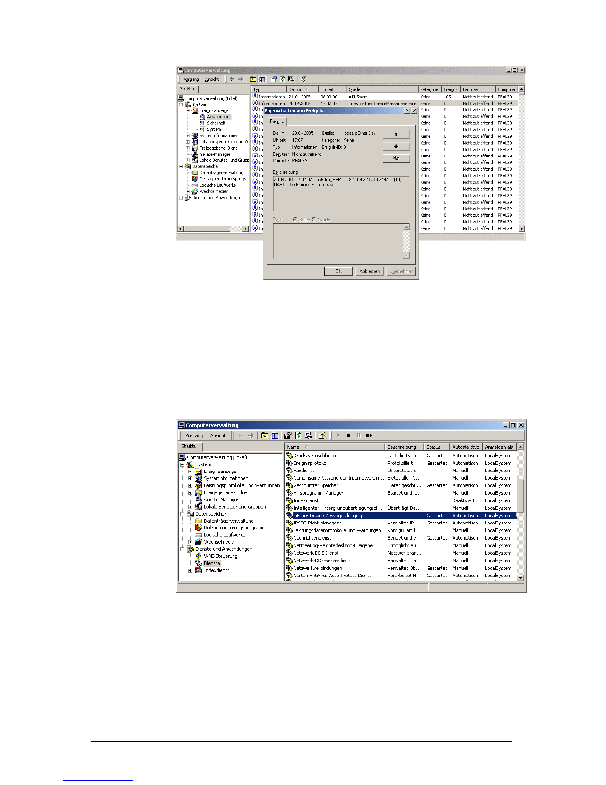
If these services are not desired, they can be stopped too.
Start and stop of the service in the computer administration
he service "ipEther message devices logging" can be activated or deactivated
nder "Services and applications". A list of all services is announced after a right
r" -> administration -> services and applications
ht cl
"terminate" it.
T
u
click on "My Compute
-> services. With a rig ick on the service you get the options to "start" or
Start and stop of the service through the c
In the command shell the
started with the command
stopped with the comman
The driver-service for the
start ipether232” and stop 32”.
ommand shell
service „ipEther Device Messages logging“ can be
“net start ipcas.ipether.devicemessageservice“ and
d „net stop ipcas.ipether.devicemessageservice“.
virtual Com-Port can be started with the command “net
d “net stop ipether2ped with the comman
Änderungen vorbehalten Stand 09.09.05
ipcas GmbH ipEther232 V11.01 Seite 29 von 150
Page 30

Änderungen vorbehalten Stand 09.09.05
ipcas GmbH ipEther232 V11.01 Seite 30 von 150
Page 31

Chapter 4: Configuration of ipEther232
4.1 Configuration of ipEther232
As mentioned above, the configuration program recognizes all devices in its own
network segment.
A double click on an entry opens the details dialog which contains on six parts.
TCP/IP:
This is where you can find the MAC-Address, IP-Address and the setted device
name (Set Name).
Mode:
Here you can chose between 2 supported modi.
Änderungen vorbehalten Stand 09.09.05
ipcas GmbH ipEther232 V11.01 Seite 31 von 150
Page 32

Compatibility Mode:
On UDP based protected data transmission that
makes a certain data communication possible but it
fast UDP plaintext transmission and can be used for
time-critical protocol / data.
In addition this mode makes possible to open 4
dataconnections on the same time.(enable more than
one pc). Redundant installations / data connections is
wn UDP based Socket
can use it on the further
parameters, communication diagram and a
example program from this you have the C#
sourcecode. In addition you will find more information
about this topic on following chapters.
costs more time by the data transmission.
You take it for time-critical protocols / data
Transparent UDP Mode:
A
made possible.
The Transparent UDP Mode is perfect for your own
UDP „socket“ based developments, too
It´s perfect for your o
developments.
For this you find function parameters, communication
diagram and example program from this you find the
C# sourcecode and you
chapter
Function
Änderungen vorbehalten Stand 09.09.05
ipcas GmbH ipEther232 V11.01 Seite 32 von 150
Page 33

This is where you can find the MAC-Address, IP-Address and the setted device
name (Set Name).
Änderungen vorbehalten Stand 09.09.05
ipcas GmbH ipEther232 V11.01 Seite 33 von 150
Page 34

TC 57 settings
The advantage of the TC 57 settings is that on reception of a frame of this format
(from the RS232 line) the frame is immediately sent on to the Ethernet without
having to wait for a timeout. This greatly improves communication speed and
performance.
The IEC 60870-5-1 and IEC 60870-5-2 norms define four standard frame formats
for the link layer. They are:
• Format FT 1.1
• Format FT 1.2
• Format FT 2
• Format FT 3
The Frame with FT 1.2, FT 2 and FT 3 have a frame of fixed length.
The Frame includes “Start character”, “Length”, “User Data” and “Check
sequence”.
The user must select the desired Format and include values for “Fixed frame
length” and “Header length” parameters.
The range of edit field “Fixed frame length” is from 2 to 255 bytes.
The range of edit field “Header length” is from 2 to 14 bytes. This value only
relates to the “user data” from the header.
SEE IEC 60870-5-1 IEC 60870-5-2
Änderungen vorbehalten Stand 09.09.05
ipcas GmbH ipEther232 V11.01 Seite 34 von 150
Page 35

RS232:
„Com-Port“: set the COM-Interface which should be used (e.g.: COM9).
„Half duplex mode (RS485)“: During the sending process to the serial interface
the receiving device is switched off. All data received at this time is ignored
(RS485 as a 2 wire solution).
„NoModemSignals“: All controlling signals to the serial interface are ignored.
Timeouts:
„Total Read Timeout“: In most cases the default value of 100 ms can remain
unchanged.
„Character Distance“: Only in very few cases does the default value of 5 ms need
adjusting.
Please refer for further information about these two parameters: Technical Details
(Receiving).
The entered COM port will exist in your computer and can be used immediately
once the configuration program is closed.(see chapter:”4.2 Checking the
adjusted Com-Ports)
Änderungen vorbehalten Stand 09.09.05
ipcas GmbH ipEther232 V11.01 Seite 35 von 150
Page 36

PortAssignment
used ComPorts (MAC-, IP-Address and comments). Overview of the
Änderungen vorbehalten Stand 09.09.05
ipcas GmbH ipEther232 V11.01 Seite 36 von 150
Page 37
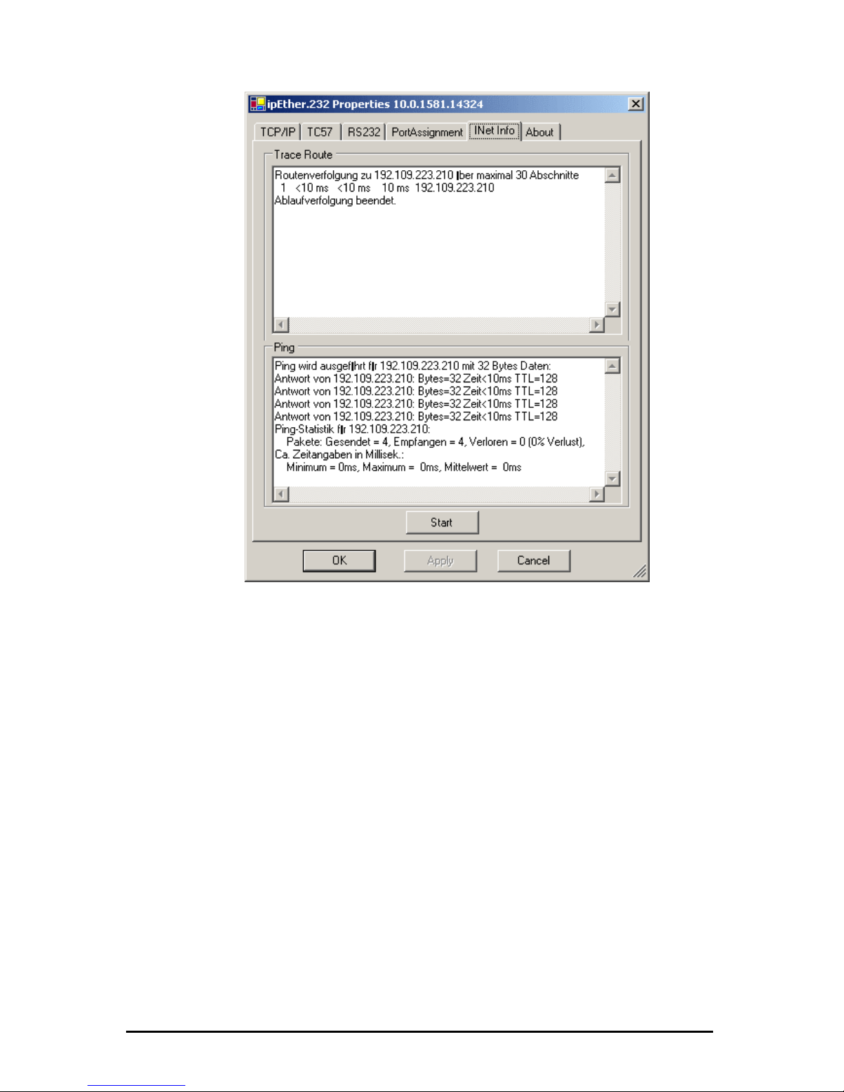
Traceroute
Over traceroute you can see the data path between two servers in the internet.
Traceroute lists all servers, which are between the respective traceroute-server
and the destination adress.
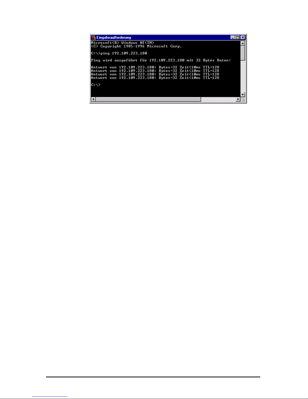
Ping
Ping is an application of the ICMP (Internet Control Message Protocol RFC 792).
This protocol (also a component of the IP protocol) transfers different
administrative information and can therefor also be used for fault-tracing. If the
ping signal meets an object, it’s reflection (echo) that can be received from the
appropriate transmitter again. So ping can find out whether the IP address is
active (if a connection could be established) and how fast it is.
Änderungen vorbehalten Stand 09.09.05
ipcas GmbH ipEther232 V11.01 Seite 37 von 150
Page 38

About
Informationsite
Änderungen vorbehalten Stand 09.09.05
ipcas GmbH ipEther232 V11.01 Seite 38 von 150
Page 39

If you want to check your adjusted COM-Port is really free and available you can
write the command “mode” in the command shell. After you have pressed the
“Return” key you will see the following Output:
4.2 Checking the adjusted Com-Ports
It will display all available and not resevered COM-Ports.
The Device Manager will not detect the seriell Interface from the ipEther232
because it’s a virtual Interface and not a physical COM-Interface from the PC.
You can check the virtual interface via "Hyperterm“, too. This program is part of
Windows and you find it under Program / Accessories / Communication.
Änderungen vorbehalten Stand 09.09.05
ipcas GmbH ipEther232 V11.01 Seite 39 von 150
Page 40

4.3 Parameter (Transparent UDP Mode)
Function UDP-Port
Control Port
3497
Data Port
3498
.6
ipEther232
Version 11
Command Answer Description
“open” ve “ok” or “error” Opens the Connection or keep it ali
“openex” Opens the Connection exclusively or
keep it alive
“ok” or “error”
“open password” “ok” or “error” Like “open” but with Password
“openex password” “ok” or “error” Like “openex” but with Password
“close“ “ok” or “error” Closes the Connection
“mode” “mode 9600,8,n,1” Get the current UART Mode
“mode 9600,8,n,1” “ok” or “error” Sets the UART Mode
“tc57” “tc57 mode,fl,hl Get the current TC57 Mode. See
ipEther-Docu
“tc57 no” “ok” or “error” Disables the TC57
“tc57 1.1” “ok” or “error” Sets the TC57 Mode to Format 1.1
“tc57 1.2, fl” “ok” or “error” Sets the TC57 Mode to Format 1.2
“tc57 2, fl,hl” “ok” or “error” Sets the TC57 Mode to Format 2
“tc57 3, fl,hl” “ok” or “error” Sets the TC57 Mode to Format 3
“rxdtimeout”
“rxdtimeout 100”
Get the current RXD-Timeout. See
ipEther-Docu
“rxdtimeout 100” “ok” or “error” Sets the RXDTimeout.
“chartimeout”
“chartimeout 100”
Get the current Character Distance.
See ipEther-Docu
“chartimeout 100” “ok” or “error” Sets the Character Distance.
“nomodemsignals 1” “ok” or “error” 1=Ignores the Modemsignals, 0=Uses
the Modem
Mode: Baudrate,DataBits,Parity,StopBits
Baudrate: 2400, 4800, 9600, 19200, 38400, 57600, 115200
DataBits: 7, 8
Parity: n, e, o, 1, 0 (= None, Even, Odd, Mark, Space)
StopBits: 0, 1, 2
TC57: Mode to Format, Length of the Fixed Frame, Length of Header
The Frame Format FT 1.2, FT 2 and FT 3 have a Frame with fixed length.
The transmission frame formats - FT 1.2, FT 2 and FT 3 have a Frame of fixed
length.
The Frame with variable length for FT 2 and FT 3 have a header of fixed length.
It includes “Start character”, “Length” byte, “User Data” and “Check sequence”.
The user must select the desired Format and include values for “Fixed frame
length” and “Header length” parameters.
Mode: Frame-Format - 1.1, 1.2, 2, 3
Fl: Length of the Fixed Frame - Bereich 2 … 255 bytes
Hl: Length of Header - Bereich 2 … 14 bytes
See IEC 60870-5-1 IEC 60870-5-2
Änderungen vorbehalten Stand 09.09.05
ipcas GmbH ipEther232 V11.01 Seite 40 von 150
Page 41

4.4 Kommunikationsdiagramm (Tran sparent UDP Mode)
ipEtherPC
Create Socket()
yPort = Bind()m
Returns e.g. 1234
[
1
2
3
4
]
“
o
p
e
n
”
[
3
4
9
7
]
“any Data to Transmit”
“some receive Data”
“
o
k
”
[
1
2
3
4
]
[
3
4
9
7
]
Open Connection
“
a
n
y
D
a
t
a
t
o
T
r
a
n
s
m
i
t
”
[
3
4
9
8
]
[
1
2
3
4
]
“
s
o
m
e
r
e
c
e
i
v
e
D
a
t
a
”
Trans atamit DReceive DataKeep Connection alive
Close Connection
“
o
p
e
n
”
[
1
2
3
4
]
[
3
4
9
7
]
“
o
k
”
[
1
2
3
4
]
[
3
4
9
7
]
“
c
l
o
s
e
”
[
1
2
3
4
]
[
3
4
9
7
]
“
o
k
”
[
1
2
3
4
]
[
3
4
9
7
]
Get Status
Close Socket()
RS232
RS232
“
T
-
0
0
0
0
R
-
0
0
0
0
D
C
D
=
0
D
S
R
=
1
C
T
S
=
1
R
I
=
0
”
[
1
2
3
4
]
[
3
4
9
7
]
[
1
2
3
4
]
[
3
4
9
8
]
“
o
k
”
[
1
2
3
4
]
[
3
4
9
7
]
Setup UART
“
m
o
d
e
9
6
0
0
,
8
,
n
,
1
”
[
3
4
9
7
]
[
1
2
3
4
]
Änderungen vorbehalten Stand 09.09.05
ipcas GmbH ipEther232 V11.01 Seite 41 von 150
Page 42

.5 Sample for ipEther232 (Transparent UDP Mode)
The standard settings of installationpath is “C:\Programme\ipcas GmbH\ipcas
Ethernet Products\ipEther232 Programing Samples\.....” for the described
sampleprogram and sourcecode. You can install it from the Setup CD.
Form1.cs
The file „Form1.cs“ is the C# sourcecode for the sample application on
transparence UDP Mode
4
Änderungen vorbehalten Stand 09.09.05
ipcas GmbH ipEther232 V11.01 Seite 42 von 150
Page 43

4.6 Technical details for ipEther232
During the development we arragened our attention on the compatibility of the
“virtual” serie dard drivers. The Ethernet makes som
restrictions necessary
• There are delays
• The device has to
• The Xon / Xoff han not su ported at the moment.
Send
Between the call „Writefile” on the a of the first byte
at the interface it takes approx. 5millise ytes of the task
are issu delay. In case of sy ous write
returns app after th he interfac
For each call iteFile“ functio enters the Ethe
least. If po hould be
On data reception blocks have to be a
To do this, there are two timeouts available in 2.
1. ead Time
2. “Character Dist
T
a
l
R
e
a
d
T
i
m
e
o
u
t
“
.
4. “
Reception of the first byte starts the "Total Read Time". After this has expired all
characters received until then are sent to the PC. This value must not fall below
the travel time of the udp packet in the Ethernet. Use the "ping" tool to determine
the travel time. The default value for this parameter is 100 ms.
Fine tuning might be required for time critical applications as well.
ll driver with the stan e minor
build blocks of Data
dshake is p
pplication and the appearance
conds. All subsequent b
ed at the interface without
rox. 5 milliseconds
nchron
e last byte appears at t
the call
e back.
rof function "Wr n one packet net at
ssible, only blocks s written.
Receiving
ssembled.
ipEther23
„Total R out“.
ance”.
3. „
o
t
Änderungen vorbehalten Stand 09.09.05
ipcas GmbH ipEther232 V11.01 Seite 43 von 150
Page 44
here < 10ms + 10ms = 20ms
The "Character Distance" is the maximum distance between two character
received. If this value is exceeded, all characters received until then are sent on
the PC. The blocking function does not directly affect the application, but it can
help reduce the network load. Only in very few cases does the default value of 5
ms require adjusting.
r "Application Programing Interface“ (API) is identical to the serial
ith
32. All functions are available, but the timing might be slightly different.
UART
smission speeds between 2400 baud and 115200 baud.
ight result in data loss if data is transmitted continuously.
throughput time + 10ms = ideal “Total Timeout“
Windows API
The drive
Windows driver, enabling all applications which use this interface, to work w
ipEther2
The UART supports tran
Higher baud rates m
7 or 8 data bits can be used.
The parities "none“, "even“, "odd“, "1“ and "0“ are supported.
7 bit data does not support the parity "none".
Änderungen vorbehalten Stand 09.09.05
ipcas GmbH ipEther232 V11.01 Seite 44 von 150
Page 45

Further technic al details
ipEther232
OEM Version Desktop Din-Rail-Unit
1 x RS232 or 1 x RS485 – SUB-D9 (Full RS232)
Baudrate: 2.400 TP 115.200 baud
Parity: None, Even, Odd, Mark, Space
Data: 8 Bits
Stop: 1 or 2 Bits
Interfaces
1 x 10BaseT – RJ45 (may be operated in 10/100 MBit/s networks)
Diagnosis (LED)
Power, System, Error,
RS232 bzw. RS485 Send/Receive,
Ethernet Send/Receive/Link
Supply voltage
+ 8 - 14 V DC – ack 5 V I t Jnpu
DC on-board connector
+ 8 - 14 V DC – Input Jack
+ 8 - 14 or 24 V DC
1)
Input Jack and
3,5mm connector
Housing Without housing Plastic housing Plastic housing
Dimensions W/H/D Approx. 10 m 0/20/70 m Approx. 110/30/75 mm Approx. 45/108/73 mm
Operating / storage temperat e ur 5° C to 55° C / -10° C to 70° C
Relative humidity 5 % to 90 % non condensing
Standards CE
ipEther232
Without power supply
External power supply input: 230
V AC Output: 9 V DC
Without power supply
Configuration software
Driver for Windows (NT, 2000, XP)
Scope of delivery
Documentation (German or English)
RS232 0202014-OEM 0202014 0202014-H
Order number
RS485 0202015-OEM 0202015 0202015-H
1)
Further voltages on request
2)
Delivery only at countries with 230 V AC 50Hz
Änderungen vorbehalten Stand 09.09.05
ipcas GmbH ipEther232 V11.01 Seite 45 von 150
Page 46

Chapter 5: Co n guration of
5.1 Configuration of ipEther232.Te
By a right click on device of entry under the option “Set ip” you can give your
fi ipEther232.Telnet
lnet
ipEther232.Telnet a legal ip adresse.
5.2 Connect
et you can make a ping on the device.
e command shell.
and line.
s you type„pi “ on the command line.
.3 The Commando-Port
In the command shell you type „telnet [IP-Adress from the device] [Port]“ to
ate a Telnet Connection. On the firmware the commandport is selected to
97. If you forget the commandport input telnet will connect to standard port 23
but this port is only for Data transmissions.
ion Test to ipEther232.Telnet
If you want test the ipEther232.Teln
For Windows systems you type „ping IP-Adress“ on th
e commFor Linux systems you type„ping –s IP-Adress” on th
For Solaris system ng –s IP-Adresse 32
5
cre
34
Änderungen vorbehalten Stand 09.09.05
ipcas GmbH ipEther232 V11.01 Seite 46 von 150
Page 47

Wenn das Gerät durch ein Passwort geschützt ist, wird dieses vorher abgefragt.
Das Passwort wird von Telnet nur in Großbuchstaben akzeptiert. Das bedeutet,
wenn im Configtool das Passwort „test“ vergeben wurde, wird von Telnet nur das
tected through a password you have to type it before you can
work with the device. Telnet is only accepted capitel letters. That means if you
5.4 Paramet
Passwort „TEST“ akzeptiert.
If the device is pro
type “test” on the configtool for the password, telnet is only accept the
password”TEST”.
er
If you want a overview about all parameters type „?“ and press the “Return” key.
The parameters, their default values and their meanings
Function TCP-Port
Control Port
3497
Data Port (default Telnet)
23
Data Port
57137
Remote Port (GW Mode)
57138
ipEther232.Telnet
Version 10.6
Command default Answer Description
“?”
“mode 115200,8,n,1”
“tc57 mode,fl,hl “
“rxdtimeout 200“
“chartimeout 0“
“nomodemsignals 0“
“rs485halfduplex 0“
“echo 1”
“subnetmask
“tcptimeout 1800”
“portdata 57137”
Get the current UART Mode.
Get the current TC57 Mode.
Get the current RXD-Timeout.
Get the current Character Distance.
Get the current modem Mode.
Get the current Duplex Mode.
Get the current Echo Flag.
Get the current Subnet Mask.
Get the value of connection life Timeout
Get the current Port Data.
255.255.255.0”
“gateway 10.10.5.1”
Get the current Gateway.
Änderungen vorbehalten Stand 09.09.05
ipcas GmbH ipEther232 V11.01 Seite 47 von 150
Page 48

“remoteip 0.0.0.0”
“remoteport 57138”
“gwsource 0”
Get the current Remote IP (GW Mod
Get the current Remote Po
Get the curre
“gwidleto 120”
e).
rt(GWMode).
nt QW Source (GWMode).
Get the current QW Idle Timeout (GW Mode).
“mode 9600,8,n,1” “ok” or “error” Sets the UART Mode
“tc57 no” “ok” or “error” Disables the TC57
“tc57 1.1” “ok” or “error” Sets the TC57 Mode to Format 1.1
“tc57 1.2, fl” “ok” or “error” Sets the TC57 Mode to Format 1.2
“tc57 2, fl,hl” “ok” or “error” Sets the TC57 Mode to Format 2
“tc57 3, fl,hl” “ok” or “error” Sets the TC57 Mode to Format 3
“rxdtimeout 200” “ok” or “error” Sets the RXDTimeout. (10, 20, …30000ms)
“chartimeout 0” “ok” or “error” Sets the Character Distance.(0, 10,…250ms)
“nomodemsignals ” “ok” or “error” 1=Ignores the Modem signals, 0=Uses the
Modem.
1
“rs485halfduplex 0“ “ok” or “error” 1=Full, 0=Half duplex mode.
“echo 1” “ok” or “error” 1=Echo enable, 0=Echo disable.
“subnetmask
255.255.255.0”
“ok” or “error” Sets the subnet mask.
“gateway 10.10.5.1” “ok” or “error” Sets the gateway.
“tcptimeout 1800” “ok” or “error” Set the time out for TCP connection.
(60…4294967294sec.)
“portdata 57137” “ok” or “error” Set the data port number. (0 … 65535)
“remoteip 0.0.0.0” “ok” or “error” Set the remote IP address.
0.0.0.0 - Telnet server mode.
x.x.x.x – Telnet client mode.
“remoteport 57138” “ok” or “error” Set the remote port number. (0 … 65535)
“gwsource 0” “ok” or “error” Sets the condition to open a TCP connection
in Gateway mode.
“gwidleto 120” “ok” or “error” Sets Time out. This parameter is active when
gwsource=0. (0… 65535sec.)
„T=3000 R=2FCC DSR=1
CTS=1 DCD=1 RI= “
--- Receives the ipEther.Telnet Status.
0
“uarterror 1” --- Receives the UART status.
“exit” --- Exit from Command Telnet Terminal.
Mode: audrate,DataBits,Parity,StopBits B
Baudrate: 400, 4800, 9600, 19200, 38400, 57600, 115200
ataBits: 7, 8
arity: n, e, o, 1, 0 (= None, Even, Odd, Mark, Space)
topBits: 0, 1, 2
C57: Mode to Format, Length of the Fixed Frame, Length of Header
2
D
P
S
T
The transmission frame formats - FT 1.2, FT 2 and FT 3 have a Frame of fixed
length.
The Frame with variable length for FT 2 and FT 3 have a header of fixed length. It
includes “Start character”, “Length” byte, “User Data” and “Check sequence”.
The user must select the desired Format and include values for “Fixed frame
length” and “Header length” parameters.
Fl: ch 2 … 255 bytes
Hl: ereich 2 … 14 bytes
Length of the Fixed Frame - Berei
Length of Header - B
Änderungen vorbehalten Stand 09.09.05
ipcas GmbH ipEther232 V11.01 Seite 48 von 150
Page 49

See IEC 60870-5-1 IEC 60870-5-2
GW Source: Number
Number: 0
er when receive data from RS 232 line. Close the TCP
nnection with Time Out – gwidleto;
1 Connect to the Server when DSR is On, close the TCP connection when DSR is
ff;
2 en received RI signals, close when DCD is Off (only
th modem)
Status:
- Connect to the Serv
Co
-
O
- Connect to the Server wh
wi
Free Tx Bufer, Free Rx Buffer, Modem signals
Free Tx Buffer: 0h … 3000h
Free Rx Buffer: the range is - 0000h … 3000h
Modem Signale: DSR, CTS, DCD and RI
UART Status:
the range is - 000
Error Code
Error Codes:
- Ov
8 - Br
Note 1: des – TelNet Server or TelNet Client
ter remoteip is 0.0.0.0, then is activated TelNet Server
possible the Telnet clients to open one TCP connection for
mmand channel and two TCP connections for Data channels at the same
me.
eter remoteip is x.x.x.x then is activated TelNet Client Mode.
r232.TelNet opens the TCP connection with remote server
el. It is possible the Telnet client to open one TCP
channel at the same time.
Note 2: Whe the fo the xit” command.
ipEt w values are set.
Para , tcptimeout, portdata, remoteip,
Note 3: The valid va eters rxdtimeout and chartimeout are rate frequency
to 10 ms.
- rx
- ch , 10, 20, 30...250 ms
1 - Frame Error
2 - Parity Error
4 errun Error
eak
ipEther232.TelNet works in two mo
(Gateway Mode).
1). When the parame
ode. In this mode isM
oC
ti
2). When the param
n this mode ipEtheI
(remoteip) for Data chann
nnection for Commandco
n llowing parameters are changed then must use “e
her.Telnet makes Reset and the ne
meters: subnetmask, gateway
remoteport, gwsource
lues for the param
dtimeout - 1
artimeout - 0
0, 20, 30, …65530 ms
5.5 Datacommunication
Änderungen vorbehalten Stand 09.09.05
ipcas GmbH ipEther232 V11.01 Seite 49 von 150
Page 50

If you create a Telnet Connection to the standard port 23(data port) and open a
Hyper Terminal (Baudrate=115200, Databits=8, Parity=none, Stoppbits=1,
flowcontrol=Hardware) you can only send data from the telnet window to the
Hyper Terminal, because the RTS and DTR-Signal are not set it.
After the Com-Interface is opened type “modemstatus=12” on the command
window for activate the RTS- and DTR-Signale.
5.6 The Datencommunication (Gateway - Modus)
Is set the parameter “remoteip” than will automatically close the
telnetprogram on the standard port (port 23)
Änderungen vorbehalten Stand 09.09.05
ipcas GmbH ipEther232 V11.01 Seite 50 von 150
Page 51

5.7 Sample der ipEther232.Telnet Schnittstelle
Sample CommandChannel ()
{
Socket Cmd = OpenClientSocket (IP, 3497);
Cmd.Send(“mode 9600,8,n,1”);
Cmd.Send(“tc57 1.2,2”);
Cmd.Send(“rxdtimeout 100”);
……………………….
Cmd.Send(“chartimeout 10”);
Cmd.Close();
}
Sample GetParameters ()
{
Socket Cmd = OpenClientSocket (IP, 3497);
Cmd.Send(“?”);
Parameters = Cmd.Receive();
Print(Parameters); // print values of all parameters.
Cmd.Close();
}
I). Telnet Client:
Sample Read / Receive
{
Socket Data = OpenClientSocket (IP, 23);
Data.Send(“this will be send via RS232 line”);
Änderungen vorbehalten Stand 09.09.05
ipcas GmbH ipEther232 V11.01 Seite 51 von 150
Page 52

RcvData = Data.Receive();
Data.Close();
Print(RcvData);
}
). Telnet Server:II
Sample Read / Receive
Socket Data = OpenServerSocket (IP, 57138);
nnection();
RcvData = Data.Receive();
Print(RcvData);
ata.Send(“this will be send via RS232 line”);
}
5.8 diagram
ipEther232.Teln
{
Data.WaitForCo
D
Data.Close();
of communication
et im Server Modus:
Änderungen vorbehalten Stand 09.09.05
ipcas GmbH ipEther232 V11.01 Seite 52 von 150
Page 53

ipEtherPC
Create Socket()
S
e
n
d
S
Y
N
,
s
e
q
=
n
“any Data to Transmit”
“some receive Data”
S
e
n
d
S
Y
N
,
s
e
q
=
m
,
A
C
K
n
+
1
Passive O PEN Connection
Close Connection
Close Socket ()
RS2 32RS232
Active OPEN Connection
S
e
n
d
A
C
K
m
+
1
S
e
n
d
P
a
c
k
e
t
1
S
e
n
d
A
C
K
1
S
e
n
d
P
a
c
k
e
t
2
S
e
n
d
A
C
K
2
S
e
n
d
P
a
c
k
e
t
3
S
e
n
d
P
a
c
k
e
t
4
S
e
n
d
P
a
c
k
e
t
5
S
e
n
d
P
a
c
k
e
t
6
S
e
n
d
A
C
K
3
S
e
n
d
P
a
c
k
e
t
7
Active Connection Receiver
Active Connection Sender
S
e
n
d
F
I
N
S
e
n
d
F
I
N
ipEther232.TelNet – Server Mode
5.9 Technical details for ipEther232.Telnet
ipEther232.Telnet
OEM Version Desktop Din-Rail-Unit
Änderungen vorbehalten Stand 09.09.05
ipcas GmbH ipEther232 V11.01 Seite 53 von 150
Page 54

1 x RS232 or 1 x RS485 – SUB-D9 (Full RS232)
Baudrate: 2.400 to 115.200 baud
Parity: None, Even, Odd, Mark, Space
Data: 8 Bits
Stop: 1 or 2 Bits
Interfaces
1 x 10BaseT – RJ45 (may be operated in 10/100 MBit/s networks)
Diagnosis (LED)
Power, System, Error,
RS232 bzw. RS485 Send/Receive,
Ethernet Send/Receive/Link
Supply voltage
+ 8 - 14 V DC – Input Jack 5 V
DC on-board connector
+ 8 - 14 V DC – Input Jack
+ 8 - 14 or 24 V DC
1)
Input Jack and
3,5mm connector
Housing Without housing Plastic housing Plastic housing
Dimensions W/H/D Approx. 100/20/70 mm Approx. 110/30/75 mm Approx. 45/108/73 mm
Operating / storage temperature 5° C to 55° C / -10° C to 70° C
Relative humidity 5 % to 90 % non condensing
Standards CE
ipEther232.Telnet
Without power supply
External power supply input:²
)
230 V AC Output: 9 V DC
Without power supply
Configuration software
Driver for Windows (NT, 2000, XP)
Scope of delivery
Documentation (German or English)
Order number RS232 0202020
1)
Further voltages on request
2)
Only Delivery in countries with 230 V AC 50 Hz
Änderungen vorbehalten Stand 09.09.05
ipcas GmbH ipEther232 V11.01 Seite 54 von 150
Page 55

Chapter 6: ration of ipEther232.Modem
6.1 Configuration of ipEther232.Modem
or more details see chapter 2.6 Serial Configuration and chapters 3 & 4).
e, the configuration program recognizes all devices in its own
.
an entry opens the details dialog which contains six parts.
Configu
You can also set up your ipEther232.Modem with a serial configuration using AT
commands.
(f
As mentioned abov
network segment
A double click on
TCP/IP:
This is where you can find or set the device name (Set Name) and the MACAddress, IP-Address.
Here you can make further network configurations like Gateway, Subnet Mask
and automatically Connect to IP.
„automatically Connect to IP“: Enter the IP address of the "communication
partner" where a connection is to be set up automatically (Leased line). After a
connection break-off there is an automatic attempt at restoring the link.
Änderungen vorbehalten Stand 09.09.05
ipcas GmbH ipEther232 V11.01 Seite 55 von 150
Page 56

RS232:
Baud rate, databits, parity and stopbits are adjusted to the communication
behavior of the serial terminal device.
"Total Timeout": In most of cases the applied default value is 100 ms. The "ping"
tool assists in determining the ideal throughput time (see below) or with the dialog
“INet Info”.
"Character Distance" with a default value of 5 ms requires adjusting only in very
rare cases.
Throughput time + 10ms = ideal “Total Timeout“
here < 10ms + 10ms = 20ms
Änderungen vorbehalten Stand 09.09.05
ipcas GmbH ipEther232 V11.01 Seite 56 von 150
Page 57

Modem settings:
Here you can define the modem behavior.
„Answer incomming calls“: Atomatic call accept.
„local Echo on“: Command echo on.
„Quiet Mode“: Result codes on.
„Ignore DTR“: ignore DTR status change.
„RS485 (Half Duplex)“: Half Duplexcontrol for RS485 with Bussystem. During the
sending process to the serial interface the receiving device is switched off. All
ata received at this time is ignored (RS485 as a 2 wire solution).
nable Password protection“ Enable or disable serial password protection for
onnection passwords.
d
„E
c
Änderungen vorbehalten Stand 09.09.05
ipcas GmbH ipEther232 V11.01 Seite 57 von 150
Page 58

TC 57 settings:
The advantage of the TC 57 settings is that on reception of a frame of this format
(from the RS232 line) the frame is immediately sent on to the Ethernet without
having to wait for a timeout. This greatly improves communication speed and
e formats
for the link layer. They are:
Format FT 3
xed
ariable length for FT 2 and FT 3 have a header of fixed length.
es for “Fixed frame
nd “Header length” parameters.
. This value only relates to the
See IEC 60870-5-1 IEC 60870-5-2
performance.
The IEC 60870-5-1 and IEC 60870-5-2 norms define four standard fram
• Format FT 1.1
• Format FT 1.2
• Format FT 2
•
The transmission frame formats - FT 1.2, FT 2 and FT 3 have a Frame of fi
length.
The Frame with v
It includes “Start character”, “Length” byte, “User Data” and “Check sequence”.
The user must select the desired Format and include valu
length” a
The range of “Fixed frame length” is from 2 to 255 bytes.
The range of “Header length” is from 2 to 14 bytes
“user data” from the header.
Änderungen vorbehalten Stand 09.09.05
ipcas GmbH ipEther232 V11.01 Seite 58 von 150
Page 59

Traceroute
Over traceroute you can see the data path between two servers in the internet.
Traceroute lists all servers, which are between the respective traceroute-server
and the destination adress.
Ping
Ping is an application of the ICMP (Internet Control Message Protocol RFC 792).
This protocol (also a component of the IP protocol) transfers different
administative information and can therefor also be used for fault-tracing. If the
ping signal meets an object, its reflection (echo) can be received again from the
appropriate transmitter. So ping can find out whether the IP address is active (if a
connection could be established) and how fast it is.
Änderungen vorbehalten Stand 09.09.05
ipcas GmbH ipEther232 V11.01 Seite 59 von 150
Page 60

About
informationsite
Änderungen vorbehalten Stand 09.09.05
ipcas GmbH ipEther232 V11.01 Seite 60 von 150
Page 61

6.2 Serial Configuration
Connect the mains power supply to the device. The "power" light and the flashing
"system“ LED indicate that ipEther232 is operational.
The ipEther232 is connected to the PC or a serial terminal via a serial 1:1 cable.
(Basic settings: baud rate=9600, databits=8, parity=none, stopbits=1)
If the terminal tool, e.g. Hyperterm (in MS Windows to be found under Programs Accessories), is configured correctly for the connected Com port, the AT&V
command returns the current configuration of the Ethernet modem.
For more detailed explanations about the AT commands and the registers refer to
chapter AT commands.
Examples:
- Set the IP address: ATS100=192.109.223.242
- Set the baud rate to 38400: ATS31=5
- dial-up to the distant terminal: ATD 192.109.223.243
- hang up: +++ „2 sec. Pause“ ATH
- least line: ATS0=1, ATS102=192.109.223.243
(Configure distant terminal as well!!!)
.3 Configure Password Protection (Serial Devices only)
6
Änderungen vorbehalten Stand 09.09.05
ipcas GmbH ipEther232 V11.01 Seite 61 von 150
Page 62

Enable the password configuration mode:
Enter the ATP master password to enter the configuration mode. The default
master password is "000000“
ATP000000
Set up and change the passwords:
To change the master password, enter ATZ=“new master password". 9 more
passwords can be configured here (ATZ1...ATZ9).
ATZ1=ipether
Each password consists of a maximum of 8 characters (additional characters are
ignored). The password is not case-sensitive (special characters are allowed).
Enter ATZ? or ATZ1?...ATZ9? to read out all the passwords
Enable password protection:
Register 81 allows you to enable and disable the password protection.
(only in the password configuration mode)
ATS81=1 enable password protection mode
ATS81=0 disable password protection
Password blocking time:
Register S82 enables the setting of a password blocking time.
After three incorrect password entries, the modem waits for the blocking time,
before a new password query is allowed.
ATS82=120 The blocking time is 2 minutes
Valid IP addresses:
The password configuration mode allows the configuration of ten IP addresses,
for which calls are accepted. (ATR0....ATR9). If this list is empty, calls are
accepted from all partner modems.
ATR1=192.168.10.12 Calls are accepted
Save changes:
All changes only take effect after they have been saved.
The AT&W command starts the saving process.
AT&W
If the master password has been forgotten, the device must be sent in.
If the settings are not saved, all changes are lost, once the ipEther232.Modem is
disconnected from the power supply.
Quit the password configuration mode:
Enter ATP to exit the configuration mode.
ATP
The dial-up to a password protected ipEther232.Modem returns the message
"PASSWORD:“
To set up a connection, the master password or one of the 9 additional
passwords (if defined) must be entered.
An incorrect entry leads to the "WRONG PASSWORD“ message.
If a call from an IP protected modem is not accepted, the message "ACCESS
DENIED“ is issued.
Änderungen vorbehalten Stand 09.09.05
ipcas GmbH ipEther232 V11.01 Seite 62 von 150
Page 63

6.4 ipEtherModem.inf (D river-File)
ollow these instructions to install the modem driver for
F
ipEther232.Modem under Windows operating systems: e.g. for Win NT 4
Click on "Control Panel" in
the Explorer and then on
"Modems" to start the mo
installation.
dem
Check this
option for
modem
Select this option
to define the
driver location.
Änderungen vorbehalten Stand 09.09.05
ipcas GmbH ipEther232 V11.01 Seite 63 von 150
Page 64

Ple
"Bro "...
ase, select
wse
and r the location of the
.inf driver, after the
installation you will find it in:
C:P s
Gm net
Products
ente
rogram files/ipca
bH/ipcas Ether
Click on "Next"
Änderungen vorbehalten Stand 09.09.05
ipcas GmbH ipEther232 V11.01 Seite 64 von 150
Page 65
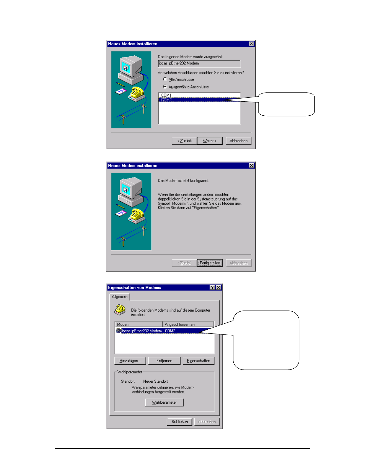
Enter the
ipEther232.Modem
interface.
After the successful
n you can
modem to
your particular
requirements with
"Dialing parameter"
installatio
adjust the
"Properties" and
Änderungen vorbehalten Stand 09.09.05
ipcas GmbH ipEther232 V11.01 Seite 65 von 150
Page 66

ommands
Up until now there has been no standardized AT command set (AT = comman
prefix Attention), each manufacturer could implement his own. The V.250
6.5 Control C
d
em"
equipped with the AT command set. A terminal program enables you to enter the
inal": This tool is part of the MS Windows
rograms - Accessories ".)
6.6 AT Comm
mmand input. Only in this
executed.
All commands directed at the Ethernet modem must be prefixed with the ASCII
by "Enter". If several
with the AT prefix and
ands with spaces.
aracter entry is
ace" key or
6.7 Tra is
ata terminal (i.e.
ne. This applies to a
t n setu well as to the answering of
his m ta transmission) between two
onnected data terminals can take place.
e and back again while the connection is up, use the
f
command set is the first industry standard available. Microsoft recommends this
command set for the PC-98 specifications and makes it a mandatory requirement
for the PC-99 specifications.
With ipEther232.Modem you have purchased a state-of-the-art "Ethernet mod
AT commands (e.g. "Hyper Term
package. You can find it under "Start - P
and Input and Execution
After power-up the Ethernet modem is ready for co
epted, interpreted andmode can commands be acc
code AT or at (not permitted: At or aT) and be followed
dcommands are to be entered, they can each be entere
"Enter". It is just as permissible to place these commands in a single line between
n introductory AT and finish the command input with the "Enter" key. a
For readability you might want to separate the individual comm
and line buffer, no further chOn reaching the end of the comm
possible. The command line can however be edited with the "backsp
executed by pressing "Enter".
nsm sion Mode
After a successful connection setup to a distant terminal, the modem changes
from the command mode to the on-line data mode..
The on-line data mode implies that a connection to a distant d
another modem) has been established: The modem is on-li
successful connec io p (outgoing call/ dialing) as
a call (call accept). In t ode data exchange (da
c
3
To revert to command mod
Escape and ATO commands. The Escape command consists of a sequence o
three Escape characters (default setting: +++) and a valid command line.
The Escape character is something completely different from the
character of
the ASCII character set an d can be changed with the S2 register.
em switches to the
efore a valid
After the three Escape characters have been entered, the mod
rrupt bcommand mode. There is, however, no transmission inte
ommand line is recognized. c
Änderungen vorbehalten Stand 09.09.05
ipcas GmbH ipEther232 V11.01 Seite 66 von 150
Page 67

1. OnlineMode
2. +++ [2-Second pause]
3. CommandMode
4. ATO
5. OnlineMode
6.8 Quick Reference for AT Commands and Registers
art sorted d AT commands and registers
enable yo uration of your Ethernet modem.
This ch by topic provides frequently use
which u to modify the config
Configurat ion Commands Registers
Basic modem initia lization AT&F
Controls the ne ialin S37, S102 con ction setup (d g) ATD
Call accept, line acce S0 pt, hang up ATA, ATD, ATH,
Switch betw S2 een command and on-line data mode +++, ATO
Read out m em in T&V od mation Afor TI, ATS, AT%V, A
Employ stor d initia e tions AT&F, AT&W liza
Controls the ffect o S37 e f DTR AT&D
Controls modem res Q, ATV, AT&D S37 ponses ATE, AT
Controls se ed ATB S31 rial spe
Password p S81, S82, S83 rotection ATP, ATZ
Callback S110 – S119 ATR
Änderungen vorbehalten Stand 09.09.05
ipcas GmbH ipEther232 V11.01 Seite 67 von 150
Page 68

6.9 Description of the AT Commands
Haye
s Commands
s command set (AT commaThe Haye nds) has over time developed into an industry
m manu addition, m rs use specific modem
eir different pr rt these c ompatible with
cturer
and makes em go off-hoo r to connect to the calling
dem. If no s ecognized afte fied time, the modem
ain.
uery and set baud ra ATB returns cur
ssign baud rate (ATB e, 2400,4800,960
B Returns the current Baud
B9600 Adjust the Baudrate to 96
ction. ATDip ess (ATDP and A ted
(P=pulse dial, T=tone dial)
D192.109.223.4 ATD192,109,2
3.4 ATDP192,109
223.4 ATDT192,109,
sable:
n
s on or off
0 modem hang n-hook), th off. Only
le in command m m al function to
t informa
2 (h
ww
standard among mode facturers. In
cts. In pa
anufacture
commands for th odu ommands are not c
modems of other manufa s.
ATA This comm
o
the mod k, in orde
remote m ignal is r r a speci
hangs up ag
ATB Q
A
te.
valu
rent baud rate.
0,19200,38400,115200 Baud)
AT rate
AT 00
funATD Dialing
ATD
addr TDT are suppressed and execu
as
AT
AT
23,4
,223,4 DP192.109.22
ATDT192.109. 223,4
ATE Command echo enable/ di
ATE0 echo off ATE1 echo o
ATH Modem goe hook.
ATH s up (goes o e connection is broken
possib ode. ATH1 mode goes off hook (identic
ATO).
ATI Return produc tion.
ATI0 ardware code)
ATI1 w.ipcas.de (w
ipE (p
V6 03 (f
uld attac odem (ma ould be saved
).
oolname
ame
ATO Return to data mode. ATO
Note: By entering the “Escape-Sequenz” (Default: +++) you can switch to
command mode during a modem connection, where AT commands can be
executed. This does not break off the connection. The ATO command terminates
the command mode.
ATP Enable and disable the password configuration mode of the modem.
ebsite)
ATI2 ther.Modem roduct name)
ATI3 .3 19.12.20 irmware, date)
ATN A toolname co
in high letters
hed to the m x. 20 Characters, it w
ATN=name To give a t
ATN? Show tooln
Änderungen vorbehalten Stand 09.09.05
ipcas GmbH ipEther232 V11.01 Seite 68 von 150
Page 69

After successful entry of the master password, passwords can only be set at the
cal RS232 interface. The master password is only for the
re only for the
racters and their
rypted de. T ord protection can be
witched on/off in the password configuration mode by setting the register 81
empty
AT&P quit the configuration mode
ATQ echo.
ATQ0 send echo ATQ1 no echo
ATR n the password
)). If this list is empty, calls
r modem.
a call from a modem is not accepted the "ACCESS DENIED“ message is
rnal Ethernet modem registers.
uery: ATSregister? ATS2? (Output "+" (default)
after 2 rings)
ATV eturn system echo of modem as character string or digits.
g", "Connect", "Busy")
possible in the password configuration mode (see
TP)).
s made
cial ch are allowed).
ATZ=master password (change master password (default:empty))
ord)
ATZ1? returns the defined password
ATZ=<Enter> Delete master password
er> Delete userpassword
AT&D
ition
AT&D1 In this case the DTR transition from ON to OFF has the following
ansition has no effect. During a
connection setup, the DTR transition from ON to OFF breaks off the connection setup. If the modem is in on-line data mode (i.e. the connection is set up), it switches to
AT&F
while there is a connection.
lo
passwordconfigurationmodus and the connection passwords a
datacomunication. Passwords have a maximum length of 8 cha
transmission is always in enc co he passw
s
(ATS81=1 enable; default = off (ATS81=0)).
ATPmaster password enable the password configuration mode (default:
ATP<Enter>)
If the master password has been forgotten, the device must be sent in.
Enable / disable modem
Ten IP addresses, for which calls are accepted, can be defined i
configuration mode (ATR0....ATR9 (Register 110-119
are accepted from any partne
If
issued..
ATRnumber=value ATR2=192.168.120.23
ATR2? read out register
ATS Set and query the inte
Q
Set: ATSregister=value ATS0=2 (i.e. the modem answers a call
R
ATV0 response is a number
ATV1 response is a character string ("Rin
A further description can be found in chapter "Result Code “.
ATZ Change passwords (only
A
Up to 9 passwords may be saved in the Ethernet modem.
Passwords consist of a maximum number of 8 characters, no difference i
between small and capital letters (spe aracters
ATZ1=password ... ATZ9=password (Set userpassw
ATZ1..9=<Ent
Interpret DTR control line.
AT&D0 ignore DTR ON/OFF trans
effects: If the modem is in command mode, the tr
the command mode.
Load default configuration. Exception Register S99. AT&F
This command is not executed
Änderungen vorbehalten Stand 09.09.05
ipcas GmbH ipEther232 V11.01 Seite 69 von 150
Page 70

AT&H alf Duplexcontrol for RS485 as 2 wire solution.
hile sending is the reception of data suppressed.
T&H1 Half Duplexmodus on
AT&H0 Half Duplexmodus off (Fullduplex; default)
AT&P eave passwordconfigurationmodus (see ATP).
AT&R
AT&V ead out and display current configuration.
T%V Display Firmware-Version (corresponds ATI3). AT%V
AT&W flash
AT&Z passwords (master password and connectionpasswords).
ee ATZ) (only in passwordconfigurationmodus (see ATP) availiable)
The following registers were not reset:
Register Definition
S1 Number of rings
S31 Baud rate
S32 Parity
S33 DataBits
S34 StopBits
S81 Password protection
S99 Time between two rings
S100 Own IP
S101 DefaultGa teway
S103 Subnetmask
S104 MAC-Addresse
S110-119 Valid IP addresses
H
W
A
AT&H? Read out Half Duplexmodus
L
Give out a chart of all setted IP-addresses which receiving calls.
(see ATR) (only in passwordconfigurationmodus (see ATP) available)
R
A
Store current configuration in
Give out a list of all
(s
Änderungen vorbehalten Stand 09.09.05
ipcas GmbH ipEther232 V11.01 Seite 70 von 150
Page 71

6.10 Overvie
ters, enabling you to modify its configuration (see
lso ATS command).
w of the registers
The modem has internal regis
a
Register Definition Default Options
S0 Auto answer 0 [0..9] rings
S1 Number of rings 0 Read only
S2 Escape Character + ASCII
S3 CR-Character 0x0d ASCII
S LF-Char ASCII 4 acter 0x0a
S5 BS-Character 0x08 ASCII
S30 Inactive-Timer 0 [0..255] ms
S31 Baud rate 3 1=2400 2=4800 3=9600 4=19200
5=38400 6=57600 7=115200
S32 Parity 0 0=None 1=Even 2=Odd 3=Mark
4=Space
S33 DataBits 8 7=7 8=8
S34 StopBits 1 1=1 2=2
S35 Rxd-Timeout 100 [5..255] ms
S36 Char-Timeout 10 [5..255] ms 0=Off
S37 Bit options 5 [0..255] decimal value
S38 Use TC57 0 [0..1]
S39 TC57 type 1 [0..3]
S40 fixed frame length 2 [2..255]
S41 User data length 2 [2..14]
S81 Password protection 0 [0..1]
S82 Password blocking time 3 [0..255] minutes 0=Off
S83 Wrong password entry 0 [0..255] in the RAM only
S99 * Time between two rings 4 [0..255] s
S100 Own IP 10.10.5.1 xxx.xxx.xxx.xxx
S101 DefaultGateway 0.0.0.0 xxx.xxx.xxx.xxx
S102 AutoRemote 0.0.0.0 xxx.xxx.xxx.xxx
S103 SubnetMask 255.255.255.0 xxx.xxx.xxx.xxx
S104 MAC address 00:09:8E:x:x:x Read only
S110 * Valid IP address 0.0.0.0 xxx.xxx.xxx.xxx
S111 * V xxx.xxx.xxx.xxx alid IP address 0.0.0.0
S112 * Valid IP address 0.0.0.0 xxx.xxx.xxx.xxx
S113 * Valid I xx P address 0.0.0.0 xxx.xxx.xxx.x
S114 * Valid I .xxx P address 0.0.0.0 xxx.xxx.xxx
S115 * Valid I .0 xx.xxx.xxx P address 0.0.0 xxx.x
S116 * Valid IP address 0.0.0.0 xxx.xxx.xxx.xxx
S117 * Valid I P address 0.0.0.0 xxx.xxx.xxx.xxx
S118 * Valid IP address 0.0.0.0 xxx.xxx.xxx.xxx
S119 * Valid IP address 0.0.0.0 xxx.xxx.xxx.xxx
* Regis ters are not issued with AT&V
Änderungen vorbehalten Stand 09.09.05
ipcas GmbH ipEther232 V11.01 Seite 71 von 150
Page 72

S0 Automatic Call Accept
0..9
0
anent memory AT&W
yo n set the 0 > 0,
tomatical
gs the modem waits it auto answers.
t within t enters
al minimum r of
a f, for inst dem
tom cally enters
S2 Esc
ange 0..255 decimal
43 (+)
permanent memory AT&W
'+++', allowing you to
ock th switchover to the command mode.
S3 Carr
0..127 decimal
13 (Carriage Return)
nt memory AT&W
S4 Linefee
he S4 register defines the linefeed character.
S5 Bac ce Character
ange 0..32, 127 decimal
efault 8 (Backspace)
tore in permanent memory AT&W
he S5 register defines the Backspace character.
Range rings
Default
Store in perm
In the
each incomin
S0 register,
g call is a
u ca
u
automatic call accept (auto answer). If S
ly answered. The value in S0 defines the
efore number of rin b
If the entered value is no he valid range, the modem automatically
e numbethe ne
ngs t
xt possible v
modem w
ue (
. I
or maximum value) defining th
ri
auheati
its
9.
ance, you enter 10 in Germany, the mo
S1 Ring Counter
Range 0..255 rings
Default 0
Store in permanent memory no
The S1 register contains the number of rings of an incoming call. The value in S1
is reset to zero, if no rings have arrived for a time span specified in the S99
register (default 5 seconds). During this time new incoming calls cannot be
distinguished and the modem cannot dial.
ape Code Character
R
Default
Store in
In the S2 register, you can define the Escape command
switch from data mode to command mode.
Values equalling 0 or >128 bl e
iage Return Character
Range
Default
Store in permane
In the S3 register, you can define the Return character.
d Character
Range 0..127 decimal
Default 10 (Linefeed)
Store in permanent memory AT&W
T
kspa
R
D
S
T
Änderungen vorbehalten Stand 09.09.05
ipcas GmbH ipEther232 V11.01 Seite 72 von 150
Page 73

S30 Inactive Timer
seconds)
off)
tore in permanent memory AT&W
the S30 register, you can set the time span the modems waits before it kills the
onnection automatically, if there has been no reception or transmission of data
ables the inactive timer.
S31 Ba
efault 3 ( = 9600 Baud)
the S31 register, you can set the Baud Rate. The baud rate defines the
nges of the transmitted signal per second.
=2400 2=4800 3=9600 4=19200 5=38400 6=57600 7=115200)
S32 Pa
y)
tore in permanent memory AT&W
register, you can set the parity bit for error detection in the case of
O s
th is even and vice versa for odd parity.
S33 Da Bits
ange 7..8
efault 8
ory AT&W
S34 Stop Bits
tore in permanent memory AT&W
ber of stop bits. One or two bits in
synchronous transmission, indicating the end of a data word (packet).
Range 0..255 (10
Default 0 (timer
S
In
c
in the meantime. 0 dis
ud Rate
Range 1..7
D
Store in permanent memory AT&W
In
number of state cha
(1
rity
Range 0..4
Default 0 (no parit
S
In the S32
asynchronous data transmission. Part of the data transmission format.
ccasionally no parity, constantly one (mark) or zero (space). Even parity mean
at the bit is set, if the data bit number
0=None 1=Even 2=Odd 3=Mark 4=Space
ta
R
D
Store in permanent mem
In the S33 register, you can set the number of data bits.
7=7 Bits 8=8 Bits
Range 1..2
Default 1
S
In the S34 register, you can set the num
a
1=1 Stop Bit 2=2 Stop Bits
Änderungen vorbehalten Stand 09.09.05
ipcas GmbH ipEther232 V11.01 Seite 73 von 150
Page 74

S35 Rxd Timeout (Total Read Time
Änderungen vorbehalten Stand 09.09.05
ipcas GmbH ipEther232 V11.01 Seite 74 von 150
out)
gister, you can set the Total Read Timeout.
fter the first byte has been received, "Total Read Time" starts. After it has
xpired, all characters received so far are sent to the PC. This value must not be
the delay of the UDP packet in the Ethernet. You can use the "ping"
ol to determine the throughput time.
S36 Ch nce)
e Character Distance.
the time span between two received characters (bytes) is greater than the
efined Character Timeout, all bytes received so far are sent to the Ethernet.
fter the Char-Timeout all received characters until there are sent to the PC. This
alue must not fall below the travel time of the udp packet in the Ethernet. Use
e "ping" tool to determine the travel time.
S37 Bit Options
ange 0..255
efault 5 (binary: 0000 0101)
tore in permanent memory AT&W
the S37 register, you can set the bit options echo, quiet, DTR, verbose, half-
uplex controlling
Range 5..255 ms
Default 100 ms
Store in permanent memory AT&W
In the S35 register, you can set the Total Read Timeout.
After the first byte has been received, "Total Read Time" starts. In the S35
re
A
e
lower than
to
ar-Timeout (Character Dista
Range 5..255 ms
Default 100 ms
Store in permanent memory AT&W
In the S36 register, you can set th
If
d
A
v
th
R
D
S
In
d
Page 75

Bit Effect Default Definition
2^7 n/c 0
2^6 n/c 0
2^5 H0 / H1 0 Half Duplexcontrol(see AT&H)
2^4 Q0 / Q1 0 Echo (Return code) on/off(see
ATQ)
2^3 n/c 0
2^2 &D0 / &D1 1 DTR control line (see AT&D)
2^1 V0 / V1 0 System return code (see ATV)
2^0 E0 / E1 1 command echo (see ATE)
00000101 binary = 5 decimal
S38 UseTC57
Range 0..1
efault 0 D
Store in permanent memory AT&W
The advantage of the TC 57 settings is that on reception of a frame of this format
(from the RS232 line) the frame is immediately sent on to the Ethernet without
having to wait for a timeout. This greatly improves communication speed and
e registers 38-41 are inactive; 1 = register 38-41
S39 TC
he IEC 60870-5-1 and IEC 60870-5-2 norms define four standard frame formats
r the link layer. They are:
= Format FT 1.1
= Format FT 1.2
at FT 2
at FT 3
The Frame w a T 2 and FT 3 have a header of fixed length.
The Frame w varia e a header of fixed length. It
includes “Start chara heck sequence
The user mu elect “Fixed frame
length” and “Header
performance.
efault = 0, this means th(D
active).
type 57
Range 0..3
Default 1
Store in permanent memory AT&W
T
fo
0
1
2 = Form
3 = Form
The transmission frame formats - FT 1.2, FT 2 and FT 3 have a Frame of fixed
length.
ith vari ble length for F
ith ble length for FT 2 and FT 3 hav
cter”, “Length” byte, “User Data” and “C
de values for st s the desired Format and inclu
length” parameters.
Änderungen vorbehalten Stand 09.09.05
ipcas GmbH ipEther232 V11.01 Seite 75 von 150
Page 76

S40 TC57 Fixed frame length
Store in permanent memory AT&W
The range of “Fixed frame length” is from 2 to 255 bytes.
S41 TC
Def t
Store in
The ran er
data ro
S81 Password
ange 0..1
efault 0
tore in permanent memory AT&W
n minutes)
Incorrect password entries are counted (in the RAM only) ATS83.
DCD is only activated in the remote modem after a successful password entry.
After three incorrect password entries the remote modem goes on-hook without
any call-back. "NO CARRIER“ appears.
S82 Password blocking time
ange 0..255
efault 3
tore in permanent memory AT&W
he blocking time is set in register 82. After three incorrect password entries the
odem allows no further password request until the blocking time is up. (0 =
nction disabled) (only in passwordconfigurationsmodus).
S83 Incorrect password entries
ange 1 Byte
efault 0
ll incorrect password entries are counted in register 83 (in the RAM only).
Range 2..255
Default 2
57 User data length
Range 2..255
aul 2
permanent memory AT&W
ge of “Header length” is from 2 to 14 bytes. This value only refers to "us
" f m the header.
protection
R
D
S
egister 81 allows enabling and disabling the password protection. R
The default value is 0 (password protection inactive).
If the password protection has been enabled the modem displays the following
behavior:
After dial-up the modem issues the "PASSWORD:“ message. The user has
three trials to enter the password correctly. Then the modem is blocked for a
definable time (see S82 i
R
D
S
T
m
fu
R
D
A
Änderungen vorbehalten Stand 09.09.05
ipcas GmbH ipEther232 V11.01 Seite 76 von 150
Page 77

S99 Time Distance between rings
AT&W
ermissible time distance between
two received rings. The default value of 7.5 seconds applies to most cases.
S100 IP Address
Range xxx.xxx.xxx.xxx
10.10.5.1
nent memory AT&W
In the S100 register, you can set your own IP address. The factory-set value of
10.10.5.1 mus to your network.
Bear in mind, when mo i , but
depends on the networ follows
the familiar syntax (e.g. 192.168.31.5).
S101 Default Gateway
Range
Default
Store in pe
In the S101 register, you can set the D u enter the
Gateway IP address, if connections to other subn orks are to be established.
S102 Auto Remote
Range
in perm
e S102 register, you can set the Auto Remote Partner. Enter the IP address
n partner" for which a connection is to be established
automatically (Leased line). After a connection break-off there is an automatic
attempt at restoring the connection. The connection set-up and take-down can be
controlled via DTR (see AT&D).
Range 10..255
Default 4 (4 seconds)
Store in permanent memory
In the S99 register, you can set the maximum p
Default
Store in perma
t be adjusted
dify ng this va cannot be chosen flue, that it reely
k address of the TCP/IP network. The input format
xxx.xxx.xxx.xxx
0.0.0.0
rmanent memory AT&W
efault Gateway. Here yo
etw
xxx.xxx.xxx.xxx
Default 0.0.0.0
Store
anent memory AT&W
In th
of the "communicatio
Änderungen vorbehalten Stand 09.09.05
ipcas GmbH ipEther232 V11.01 Seite 77 von 150
Page 78

S103 Subnet Mask
Default 255.255.255.0
AT&W
the S103 register, you can set the Subnet Mask. The Subnet Mask only needs
be entered if the IpEther232.Modem is to connect to another subnetwork. In
). Please note: The IP address also defines the network class.
.
hey can only be extended "towards the right".
S104
not be
S110-119 Valid IP Addresses
Range xxx.xxx.xxx.xxx
Default 0.0.0.0
Store in permanent memory AT&W
In register 110 to 119 IP addresses can be set for which a call is accepted. For
reading and writing the AT command ATR had to be used. If no register contains
an IP address, all calls are accepted.
If a call is not accepted by a modem, the "Access Denied“ message is shown.
6.11 Result Code
System return code as a character string or digits (see AT command ATV), if not
suppressed with ATQ1.
Range xxx.xxx.xxx.xxx
Store in permanent memory
In
to
this case enter the Subnet Mask for the subnetwork where the ipEther is located
(e.g. 255.255.255.0
This results in a Default Subnetmask (e.g. 255.255.0.0 for a Class B network)
T
MAC – Address
Range 00:09:8E:xx:xx:xx
This register contains the Mac address of the network interface, which can
changed.
Char string Digit Definition
OK 0 Command line processed
CONNECT 1 Successful connection setup
RING 2 Incoming call
NO CARRIER 3 No connection established or inactivity
timer expired
ERROR 4 Error in command input
NO DIALTONE 6 No Ethernet connection
BUSY 7 Dialed line busy
ACCESS DENIED 8 Call rejected due to failed password
authentication
PASSWORT 11 Password OK
WRONG PASSWORT 12 Wrong password
Änderungen vorbehalten Stand 09.09.05
ipcas GmbH ipEther232 V11.01 Seite 78 von 150
Page 79

Änderungen vorbehalten Stand 09.09.05
ipcas GmbH ipEther232 V11.01 Seite 79 von 150
6.12 Technical details for ipEther232.Modem
Great emphasis was placed on compatability during device design.
Due to the Ethernet, there are, however, some minor restrictions.
• Data is not transmitted in bytes to the network, but Ethernet blocks are
formed. This might result in minor delays.
• The blocking function does not directly affect the application, but might
help to reduce the network load.
• Some fine-tuning might be necessary for time critical applications as well.
This involves the two timeout parameters ("Total Read Timeout",
"Character Distance")
Block formation for serial data before transmission into the Ethernet
After the first byte arrives, "Total Read Time" starts. After the time expires, all
characters received so far are relayed to the Ethernet. The default value is 50
ms.
"Character Distance" is the maximum distance between two received characters.
If this is exceeded, all characters received so far are transmitted to the Ethernet.
The default value is 5 ms.
Page 80

U RT
he UART supports transmission speeds between 2400 baud and 115200 baud.
ght result in data loss, if data is transmitted continuously.
Further techni
A
T
Higher baud rates mi
7 or 8 data bits can be used.
The parities "none", "even", "odd", "1" and "0" are supported.
7-bit data does not support the parity "none"..
cal details
IpEther232.Modem
OEM Version Desktop DIN-Rail Unit
1 x RS232 or 1 x RS485 – SUB-D9 (full RS232)
Baud rate: 2.400 to 115.200 baud
Parity: None, Even, Odd, Mark, Space
Data: 7 or 8 Bits
Stop: 1 or 2 Bits
Interfaces
1 x 10BaseT – RJ45 (may be operated in 10/100 MBit/s networks)
Diagnosis (LED)
Power, System, Error,
RS232 bzw. RS485 Transmit/Receive,
Ethernet Transmit/Receive/Link
Supply voltage
+ 8 - 14 V DC – Input Jack
5 V DC on board connector
+ 8 - 14 V DC – Input Jack
+ 8 - 14 oder 24 V DC
1)
Input Jack and
3,5mm connector
Housing Without housing Plastic housing Plastic housing
Dimensions W/H/D Approx. 100/20/70 mm Approx. 110/30/75 mm Approx. 45/108/73 mm
Operating / storage temperature 5° C to 55° C / -10° C to 70° C
Relative humidity 5 % to 90 % non-condensing
Standards CE
ipEther232.Modem
Without power supply
External power supply
Input: 230 V AC
Output: + 9 V DC
Without power supply
Configuration software
Driver for Windows (NT, 2000, XP)
Scope of delivery
Documentation (German or English)
RS232 0202014M-OEM 0202014M 0202014M-H
Bestellnummer
RS485 0202015M-OEM 0202015M 0202015M-H
1)
Further voltages on request
2)
Delivery only into countries with 230 V AC 50Hz
Änderungen vorbehalten Stand 09.09.05
ipcas GmbH ipEther232 V11.01 Seite 80 von 150
Page 81

Chapter 7: Configuration of ipEther232.PPP
7.1 Configuration of ipEther232.PPP
As mentioned above, the configuration program recognizes all devices in its own
network segment.
A double click on an entry opens the details dialog which contains five parts.
TCP/IP (Ethernet):
his is where you can find or set the device name (Set Name) the MAC-Address
nd IP-Address.
ere you can configure the default Gateway and the Subnet Mask for the
thernet side.
(Default Gateway or no Gateway = 0.0.0.0)
fault Subnet Mask: 255.255.255.0)
T
a
H
E
(De
Änderungen vorbehalten Stand 09.09.05
ipcas GmbH ipEther232 V11.01 Seite 81 von 150
Page 82

RS232:
Baudrate and Handshake are adapted to the communication behavior of the
erial terminal device.
Modem settings (use Modem):
The modem behavior is defined here.
„Init Dialstring“: Typically the Hayes commands are used in the „init string“ for
communicating with the modem. Please refer to the modem user guide for these
commands.
„Total Timeout“: Specifies the maximum time span after which the modem
connection is cut. The default 0 disables this function.
„Idle Timeout“: Specifies the time in minutes after which the modem disconnects.
s
Änderungen vorbehalten Stand 09.09.05
ipcas GmbH ipEther232 V11.01 Seite 82 von 150
Page 83

-Adress (PPP):
ive Client this IP“: This is where you can set the IP address for the serial side.
PP Parameter negation:
„MRU-Size" specifies the maximum IP packet size. (Default = 1500)
"ACCM". The entry format is hexadecimal code. (Default = 0)
„Protocol field Compress”: Default: “Off”
„Address Control field Compress”: Default: “Off”
„Magic“: Default: “On”
The above parameters are described in more detail in the RFC-1661 and
RFC-1662.
IP
„Take IP from Server“: This is where you can specify that the IP-Adress comes
om a server. fr
„G
P
Änderungen vorbehalten Stand 09.09.05
ipcas GmbH ipEther232 V11.01 Seite 83 von 150
Page 84

Traceroute
ver traceroute you can see the data path between two servers in the internet.
e-server
ing
ing is an application of the ICMP (Internet Control Message Protocol RFC 792).
his protocol (also a component of the IP protocol) transfers different
dministative information and can therefor also be used for fault-tracing. If the
ing signal meets an object, its reflection (echo) can be received again from the
ppropriate transmitter. So ping can find out whether the IP address is active (if a
O
Traceroute lists all servers, which are between the respective tracerout
nd the destination adress. a
P
P
T
a
p
a
connection could be established) and how fast it is.
Änderungen vorbehalten Stand 09.09.05
ipcas GmbH ipEther232 V11.01 Seite 84 von 150
Page 85

About
Informationpage
Änderungen vorbehalten Stand 09.09.05
ipcas GmbH ipEther232 V11.01 Seite 85 von 150
Page 86

7.2 Configuration samples
nection
without modems on Windows 2000.
In order to create a dial-up connection Windows needs a modem. We would like
to implement a PPP direct connection without modems, therefore we have to
create a modem („Communications cable between two computers“) before.
Start in the Control Panel the “Phone and Modem Options”. Click on “Modems”
and then on the “Add” Button. Mark the option “Don’t detect my modem …” in the
new opened dialogue and click on “Next”. After that configure as follows.
The following configuration is needed to establish a PPP direct con
Änderungen vorbehalten Stand 09.09.05
ipcas GmbH ipEther232 V11.01 Seite 86 von 150
Page 87

In the following dialogue
modem (finally the ipEther232.PPP) shoul
you have to decide on which physical connection the
d be installed. After a successful
odem Options”.
Double click on “Make new connection“ in the “Network and Dial-up Connections”
and click on the “Next” Button to the following dialogue.
creation the modem should be registered in the “Phone and M
After choosing the option „Connect directly to another computer“ click on „Next“.
Änderungen vorbehalten Stand 09.09.05
ipcas GmbH ipEther232 V11.01 Seite 87 von 150
Page 88

In the next dialogue the role of this computer at this connection had to be
elected. Choose “Guest” and click on “Next”. s
The created „connection cable“ had to be selected as device. In the following
dialogues the availability and the name of the connection had to be set. These
inputs are optional.
After completing the connection can be found in the “Network and Dial-up
Connections”.
Right-click the dial-up connection and click on “Properties“. In the “General” menu
click on “Configure…” and select a fitting “Maximum Speed” appropriate to the
configured Baudrate of the ipEther232.PPP.
In the ”Networking“ menu click on “Settings” and configure as follows.
o set a login or password is not necessary, because the PAP / CHAP protocol
re not supported.
T
a
Änderungen vorbehalten Stand 09.09.05
ipcas GmbH ipEther232 V11.01 Seite 88 von 150
Page 89
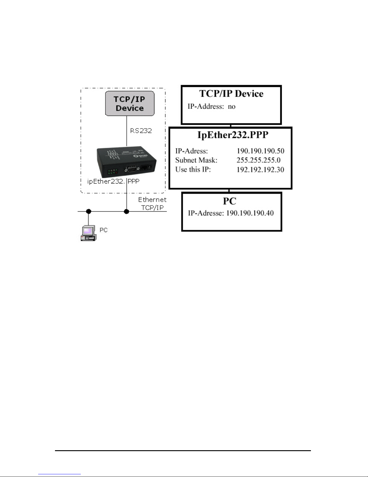
Configuration s ”
all TCP/IP enabled devices without a dedicated
Routing betwee
and on the PC.
At the example
...these commands for Windows NT / 2002
• For PPP: „ 0.40 MASK 255.255.255.0 190.190.190.50“
• For PC : “r .0 192.192.192.30”
…these comma
• For PPP: „rou
net
• For PC : „rou 90.190.50 gw 192.192.192.30
netmask 255.255.255.0 dev ppp0“
The Configuration could be tested as follows:
• For PPP:
• For PC : „ in
ample 1: “Ethernet for all
Ethernet capability for
Ethernet interface.
n two networks. A route have to be configured at the TCP/IP device
above it would be...
route ADD 190.190.19
oute ADD 190.190.190.50 MASK 255.255.255
nds for Linux-Systems:
te add –net 190.190.190.40 gw 190.190.190.50
mask 255.255.255.0 dev ppp0“
te add –net 190.1
„ping 190.190.190.50 -t“
p g 190.190.190.40 -t“
Änderungen vorbehalten Stand 09.09.05
ipcas GmbH ipEther232 V11.01 Seite 89 von 150
Page 90

Configuration sample 2: “simple Network routing”
Simple routing between two networks via GSM, ISDN or analog modems,
Routing between two networks. A route have to be configured on both PC’s.
At the example above it would be...
...these commands for Windows NT / 2002:
• For PC 1: „route ADD 192.109.223.0 MASK 255.255.255.0 10.10.7.37“
• For PC 2: “route ADD 10.10.7.0 MASK 255.255.255.0 192.109.223.242”
…these commands for Linux Systems:
• For PC 1: „route add –net 192.109.223.0 gw 10.10.7.37
netmask 255.255.255.0 dev ppp0“
• For PC 2: „route add –net 10.10.7.0 gw 192.109.223.243
netmask 255.255.255.0 dev ppp0“
The Configuration could be tested as follows:
• For PC 1: „ping 192.109.223.57 -t“
• For PC 2: „ping 10.10.7.17 -t“
Both modems have to be configured to „Answer incoming calls”.
(Normally: Register S0=1)
for instance to link up a branch to the company LAN.
Änderungen vorbehalten Stand 09.09.05
ipcas GmbH ipEther232 V11.01 Seite 90 von 150
Page 91

Configuration sample 3: „dial in“
Enables company LAN access for home office, remote
maintenance reps.
Routing between two networks. A route have to be configured on both PC`s.
At the example above it would be...
...these commands for Windows NT / 2002:
• For PPP: „route ADD 190.190.190.40 MASK 255.255.255.0 190.190.190.50“
• For PC : “route ADD 190.190.190.50 MASK 255.255.255.0 192.192.192.30”
…these commands for Linux Systems:
• For PPP: „route add –net 190.190.190.40 gw 190.190.190.50
netmask 255.255.255.0 dev ppp0“
• For PC : „route add –net 190.190.190.50 gw 192.192.192.30
netmask 255.255.255.0 dev ppp0“
The Configuration could be tested as follows:
• For PPP: „ping 190.190.190.50 -t“
• For PC : „ping 190.190.190.40 -t“
Both modems have to be configured to „Answer incoming calls“.
(Normally: Register S0=1)
or for field
Änderungen vorbehalten Stand 09.09.05
ipcas GmbH ipEther232 V11.01 Seite 91 von 150
Page 92

7.3 Logfile
After a successful PPP connection the “Messages from Device” dialog (Right
der the option “Device messages”) contains the following:
click in the configtool un
Any errors occurring during communication could be analysed under the option
„Device messages“. Simultaneously all errors are stored in the “Event viewer” of
Windows.
Änderungen vorbehalten Stand 09.09.05
ipcas GmbH ipEther232 V11.01 Seite 92 von 150
Page 93

2: ERR_RXDBufferOverrun
The UART (RS232) receivebuffer is overruned.
4: ERR_NICOverrun
The NIC (Network Interface Controller) receivebuffer is overruned.
5: ERR_SETUP_BAUD,
6: ERR_SETUP_PARITY,
7: ERR_SETUP_DATA
The UART (RS232) parameter is incorrect. Please use the configurationtool
to set the correct RS232 parameters.
9: ERR_UART_OVERRUN
Overrun Error Bit from received controlregister (UART) would be ignored.
10: ERR_UART_FRAME
Framing Error Bit from received controlregister (UART) would be ignored.
18: ERR_NIC_INTERNAL
The DMA operation on the networkcontroller (NIC) could not lead through.
23: ERR_PPP_BUFFER_OVERRUN_ETH
The Ethernet IP buffer is full. The incoming IP Packet has been ignored.
24: ERR_PPP_BUFFER_OVERRUN_PPP
The PPP (RS232) IP buffer is full. The incoming IP Packet has been ignored.
25: ERR_PPP_INVALID_MESSAGE
A wrong LCP or IPCP information would be received. The PPP Packet has
been ignored.
(Defaults for the PPP Protocol – RFC1661, RFC1662, RFC1332)
28: ERR_PPP_CRC
A PPP Packet with wrong checksum (FCS) has been received. This Packet
has been ignored.
31: PPP_IPCP_UP
authentication has been lead through. The PPP
2: PPP_IPCP_DOWN
n has been disconnected.
nnect. In this case the
aultparameter would be loaded. Please execute the configurationtool
rreset because of „Watchdog Timeout“
35: ERR_NORMAL_POWER_UP
Processorreset because of „Watchdog Timeout“
36: ERR_MCLR_FROM_SLEEP
Processorreset because of „SLEEP“
37: ERR_BROWNOUT_RESTART
Processorreset because of main disturbances
The LCP und IPCP
connection has been established.
3
The PPP connectio
33: ERR_INVALID_CONFIG
A invalid parameter would be established after the co
def
again. If the MAC Address does no more agree please contact your vendor's
customer service
34: ERR_WDT_TIMEOUT
Processo
Änderungen vorbehalten Stand 09.09.05
ipcas GmbH ipEther232 V11.01 Seite 93 von 150
Page 94

7.4 Technical details for ipEther232.PPP
reat emphasis was placed on compatability during device design.
owever, some minor restrictions:
• ipEther232.PPP can store 20 Ethernet packets that are then transmitted
rnet side. If additional packets arrive before
oo
ws size
too large or UAP connections).
• The ARP cache can hold 20 entries. If the PPP side requires more ARP
ries, the oldest entry is deleted. This might however have an adverse
• CCP (Compression Control Protocol) is not supported.
UART
The UART supports transmission speeds between 2400 baud and 115200 baud.
Higher baud rates might result in data loss, if data is transmitted continuously.
The device uses 8 Data bits and "no parity".
G
There are, h
to the RS232 or the Ethe
memory has been freed, the packet is discarded. This is however
reported and written to the error logfile (see Config tool). The problem
only occurs if too many connections are open at the same time or t
many unacknowledged packets are sent at the same time (Windo
ent
effect on the performance.
• ipEther232.PPP principally uses the "hardware handshake".
• Should problems arise, we recommend testing the connection with Linux
PPPD.
Änderungen vorbehalten Stand 09.09.05
ipcas GmbH ipEther232 V11.01 Seite 94 von 150
Page 95

Further technical details
ipEther232.PPP OEM Version Desktop DIN-Rail Unit
1 x RS232 or 1 x RS485 – SUB-D9 (full RS232)
Baud rate: 2.400 to 115.200 baud
Parity: None, Even, Odd, Mark, Space
Data: 8 Bits
Stop: 1 or 2 Bits
Interfaces
1 x 10BaseT – RJ45 (may be operated in 10/100 MBit/s networks)
Diagnosis (LED)
Power, System, Error,
RS232 bzw. RS485 Transmit/Receive,
Ethernet Transmit/Receive/Link
Supply voltage
+ 8 - 14 V DC – Input Jack
5 V DC on-board connector
+ 8 - 14 V DC – Input Jack
+ 8 - 14 oder 24 V DC
1)
Input Jack and
3,5mm connector
Housing Without housing Plastic housing Plastic housing
Dimensions W/H/D Approx. 100/20/70 mm Approx. 110/30/75 mm Approx. 45/108/73 mm
Operating- / storage temperature 5° C to 55° C / -10° C to 70° C
Relative humidity 5 % to 90 % non-condensing
Standards CE
ipEther232.PPP
Without power supply
External power supply
Input:: 230 V AC
Output: + 9 V DC
Without power supply
Configurations software
Driver for Windows (NT, 2000, XP)
Scope of delivery
Documentation (German or English)
Bestellnummer RS232 0202016-OEM 0202016 0202016-H
1)
Further voltages on request
2)
Delivery only into countries with 230 V AC 50Hz
Änderungen vorbehalten Stand 09.09.05
ipcas GmbH ipEther232 V11.01 Seite 95 von 150
Page 96

Chapter 8: Configuration of ipNTP
8.1 Configuration of ipNTP
TCP/IP:
This is where you can find or set the device name (Set Name) the MAC-Address
and IP-Address.
Änderungen vorbehalten Stand 09.09.05
ipcas GmbH ipEther232 V11.01 Seite 96 von 150
Page 97

Shows if the synchronization of the clock is working. This box is marked first after
hows the current UTC (Universal time code), this is the current Greenwich time
ero degrees longitude). The individual clients equalize their time with the UTC
of the server and tune the time of the clients about the corresponding time zone
selection.
Good DCF77 Signal
hows whether the DCF77 signal will receive. S
Clock Synchronized
a good DCF77 signal was 60 seconds long received.
ime T
S
(Z
Änderungen vorbehalten Stand 09.09.05
ipcas GmbH ipEther232 V11.01 Seite 97 von 150
Page 98

/ Multicast
ivate the Multicast and set the Multicast address.
he Multicast mode requires that the server and the clients have multicast at their
DP-Port U
Here you can configure the UDP-Port. (Default = 123)
Broadcast / Multicast Interval
adcastHere you can configure the Broadcast / Multicast interval. Bro
interval is the time period in which the NTP server transmits the alignment
information to all clients. Clients and server must be in the same Subnet.
Multicast
ere you can deactivate or actH
T
disposal and configured
Änderungen vorbehalten Stand 09.09.05
ipcas GmbH ipEther232 V11.01 Seite 98 von 150
Page 99

Traceroute
Over traceroute you can see the data path between two servers in the internet.
Traceroute lists all servers, which are between the respective traceroute-server
ing
ol Message Protocol RFC 792).
his protocol (also a component of the IP protocol) transfers different
stative information and can therefor also be used for fault-tracing. If the
reflection (echo) can be received again from the
iate ing can find out whether the IP address is active (if a
blished) and how fast it is.
or Windows systems you type „ping IP-Adress“ on the command shell.
nd line.
and the destination adress.
P
Ping is an application of the ICMP (Internet Contr
T
admini
ping signal meets an object, its
appropr transmitter. So p
connection could be esta
F
For Linux systems you type„ping –s IP-Adress” on the command line.
For Solaris systems you type„ping –s IP-Adresse 32“ on the comma
Änderungen vorbehalten Stand 09.09.05
ipcas GmbH ipEther232 V11.01 Seite 99 von 150
Page 100

About
Informationpage
Änderungen vorbehalten Stand 09.09.05
ipcas GmbH ipEther232 V11.01 Seite 100 von 150
 Loading...