

Page 1

ipEther232.Modem
User Guide
ipcas GmbH
Wetterkreuz 17
91058 Erlangen
Germany
Phone: +49 9131 7677 0
Fax:: +49 9131 7677 78
Internet: http://www.ipcas.de
Email: info@ipcas.de
Page 2

Subject to modif ic ations Last Update 22. 10. 03
ipcas GmbH ipEther232.Modem V6.01 Page 2 of 44
Legal Information f or Customers
We have do ne ou r utmost to ensure t h at the i nforma ti on in thi s
user guide is complete, accurate and up to date. In so far as legally
possible, we cannot accept any liability for consequential damage
caused by using this guide. In other respects we shall accept
liability for intention and gross negligence only. We cannot provide
any warranty that changes to third-party equipment referred to in
this guide will have no effect on the applicability of the information
provided in this guide.
The author reserves all rights, including the right to reproduce this
guide in full or part thereof in any form whatsoever.
The content is subject to change without prior notification.
The product is subject to technical change without prior notification.
All trade marks mentioned in this manual are stated for
identification purposes and may be the property of the various
holders.
Important Information
· The device should be used exclusively with the mains unit
supplied. Using a different power supply unit may result in damage
to the device.
· Use a dry cloth only to clean the operating panel and the housing.
· If the device is damaged, disconnect from the mains. Arrange for
immediate repair.
· Before contacting your vendor's customer service, please consult
this user guide.
· Using customer service during the warranty period may incur
costs, if the fault or problem was caused by the customer and the
solution or remedy is described in this guide.
· Re m o vin g th e seri al nu mber will voi d the wa rranty ri gh t s.
· Damage caused by inappropriate packing will not be borne by
the forwarding agent / insurance company.
Note !
IpEther232 is a Class A device. This device can cause interferences
to radio communications in residential areas; in such cases the
operator may be ordered to carry out and pay for appropriate
measures.
This warning does not apply to desktop housing or the OEM version
w ithout housing.
Page 3

Subject to modif ic ations Last Update 22. 10. 03
ipcas GmbH ipEther232.Modem V6.01 Page 3 of 44
Important Safety Informat ion
As is the case with all electrical equipment there are some basic
safety precautions to be observed. These safety precautions are
primarily for you own safety but also serve to prevent damage to
the device.
Settings not described in this guide and changes to the device
electronics are to be carried out by an authorized vendor only.
Read the user guide carefully and keep it to hand.
Make sure that...
· the device is placed on a stable, flat surface;
· for rail mounted devices the top hat rail is sufficiently grounded
and the rail spring has good contact;
· the device is never placed near a heater or the air outlet of an
air-conditioning unit;
· the device is never exposed to direct sunlight;
· the device is never in direct contact with liquids of any kind.
Never use liquids in the vicinity of the device.
· Opening the housing may lead to an electric shock and other
damage. Never make any changes to the device that are not
described in the user guide. This could result in damage to the
device and you would have to pay for the repairs. Only the
authorized vendor may modify the input voltage, should this
becom e nece ssary.
Install the device
Make sure that...
· the mains supply values are the same as the designation on the
power supply unit. In case of doubt contact your supplier.
· the mains is protected against surges and other disturbances.
· the mains socket is located near the device and is easily
accessible.
· you pull the mains plug completely to disconnect.
· the maximum power rating of an extension cable or multiple
contact plug, if used, is not exceeded.
· the mains cable is protected against damage. Do not place
anything on the cable and put it down, so that there is no danger
of stepping on or tripping over it.
· a damaged mains cable is replaced immediately.
· the mains cable is disconnected before starting to clean the
device. Use a dry cloth only. Do not use any liquid or aerosol
cl eani ng ag en t .
Page 4
Subject to modif ic ations Last Update 22. 10. 03
ipcas GmbH ipEther232.Modem V6.01 Page 4 of 44
Please follow all warnings and instructions displayed on the device itself and in
accompanying manuals. In the manual, warnings of particular importance are marked by the
symbols below.
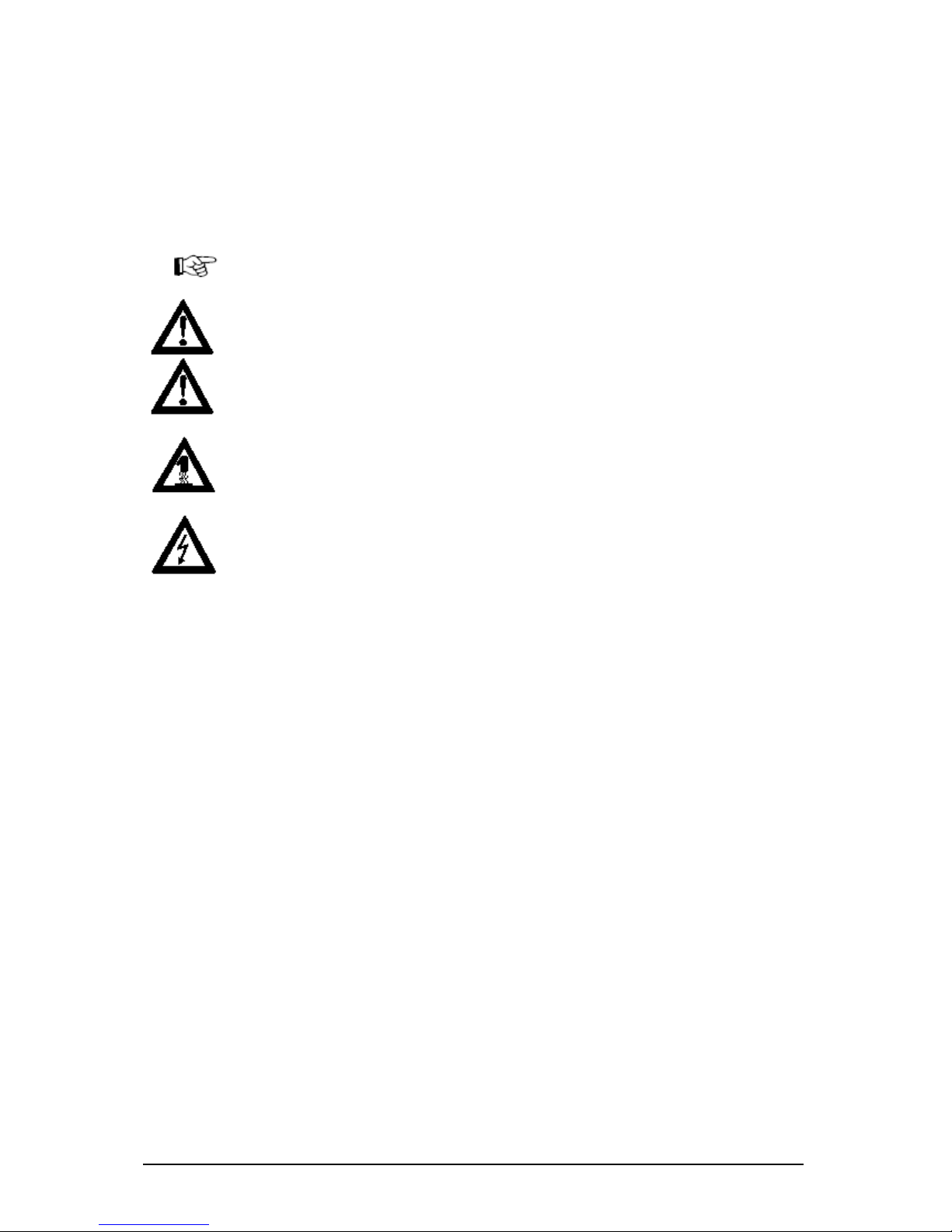
Warning and Important Information Symbols
NOTE: Text sections marked in this way contain supplementary information or hints.
WARNING - da ma ge: This warns against possible damage to the device. Follow all
instructions to avoid damage.
CAUTION - Danger of injury: This points out a possible source of danger. Follow all
safety instructions to avoid injury.
CAUTION - Hot: This points out a possible source of danger. Follow all safety
instructions to avoid heat-related injury.
CAUTION - Curre nt: This points out a possible source of danger. Follow all safety
instructions to avoid injury through electrocution.
Page 5

Subject to modif ic ations Last Update 22. 10. 03
ipcas GmbH ipEther232.Modem V6.01 Page 5 of 44
Contents Page
Chapter 1: The Device....................................................................6
1.1 Usage............................................................................................................................. 6
1.2 Sockets .......................................................................................................................... 8
Chapter2: Commissioning the ipEther232.Modem ................9
2.1 Commissioning............................................................................................................. 9
2.2 Set the I P Address....................................................................................................... 9
2.3 Configuration...............................................................................................................11
2.4 ipEtherModem.inf (Driver File)................................................................................14
2.6 Serial Configuration ................................................................................................... 17
2.6.1 Configure Password Protection (Serial Devices only)......................................18
Chapter 3: Control Commands..................................................19
3.1 AT Command Input and Execution.........................................................................19
3.2 Transmission Mode ...................................................................................................19
3.3 Quick Reference for AT Commands and Registers ............................................. 20
Chapter 4: Definition of AT Commands and Registers ...21
4.0 Chart of AT Comm ands ............................................................................................21
4.1 Register Chart.............................................................................................................24
4.2 Result Code ................................................................................................................31
Chapter 5: Technical details.......................................................32
5.1 Specifications..............................................................................................................33
5.2 Pin Assignment...........................................................................................................34
5.2.1 Pin Assignment ipEther232.Modem OEM..........................................................35
5.2.2 Power supply units.................................................................................................37
5.2.3 RS232.Modem Module..........................................................................................38
5.2.4 RS232 Module......................................................................................................... 38
5.2.5 RS485 Module......................................................................................................... 39
3.2.6 RS485 as a 2 Wire solution...................................................................................39
5.3 Measurements............................................................................................................40
5.4 Declaration of EEC Compliance..............................................................................43
5.5 Glossary.......................................................................................................................44
Page 6

Subject to modif ic ations Last Update 22. 10. 03
ipcas GmbH ipEther232.Modem V6.01 Page 6 of 44
Chapter 1: The Device
1.1 Usage
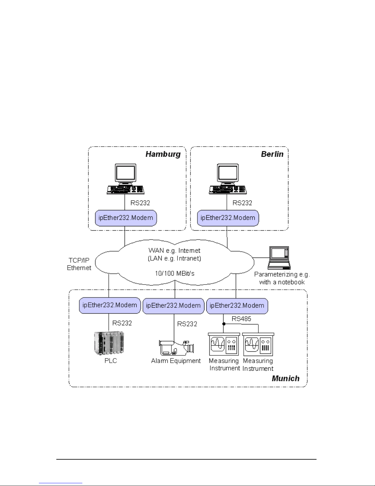
ipEther232.Modem enables you to use serial interfaces via a TCP/IP network. .
This allows you to control devices without a network interface over long
distances. In addition to the serial interface, the Ethernet modem also has a
network interface. In order to connect two serial devices simply use two modems
linked via Ethernet instead of a serial cable.
ö Terminals
ö CNC controlle rs
ö Co un ti ng de vi ces
Such devices are: ö Embedded controllers
ö Industri al switches
ö Serial printers
ö SPS controllers
ö Card scanners
ö Measuring equipment
ö UPSs
Thus all applications and devices that support terminal or modem functionalities
can also be used via the Ethernet. This has numerous advantages:
· lower telephone costs
· reduce the number of analog connections (monthly fee)
· si m pl ifie d lo gi sti cs
· extremely low porting costs
· protects your investments by converting serial devices into network
devices without necessitating changes in the existing software, saving
additional product development costs
· versatile power supply and optimal housing solutions
· serial devices can be used by several clients
· automatic setup of network connection after interruptions
· easy to setup and suitable for larger installations
· simpl e integ ration of se ri al ap pli cations
Page 7
Subject to modif ic ations Last Update 22. 10. 03
ipcas GmbH ipEther232.Modem V6.01 Page 7 of 44
"Netw orking" w ill s oon be the global standard. How ever, manufac turers
require expensive labor, precious time and comprehe nsive experience to
develop netw ork technologies. As most devices are already equipped w ith
an RS232/485 interface, the Ethernet modem offers an instant a nd ef f icient
solution for transmitting RS232/485 data via the netw ork. The Ethernet
modem not only provides added value to your product, it also adds to the
value of your existing equipment for the next generation.
Page 8
Subject to modif ic ations Last Update 22. 10. 03
ipcas GmbH ipEther232.Modem V6.01 Page 8 of 44
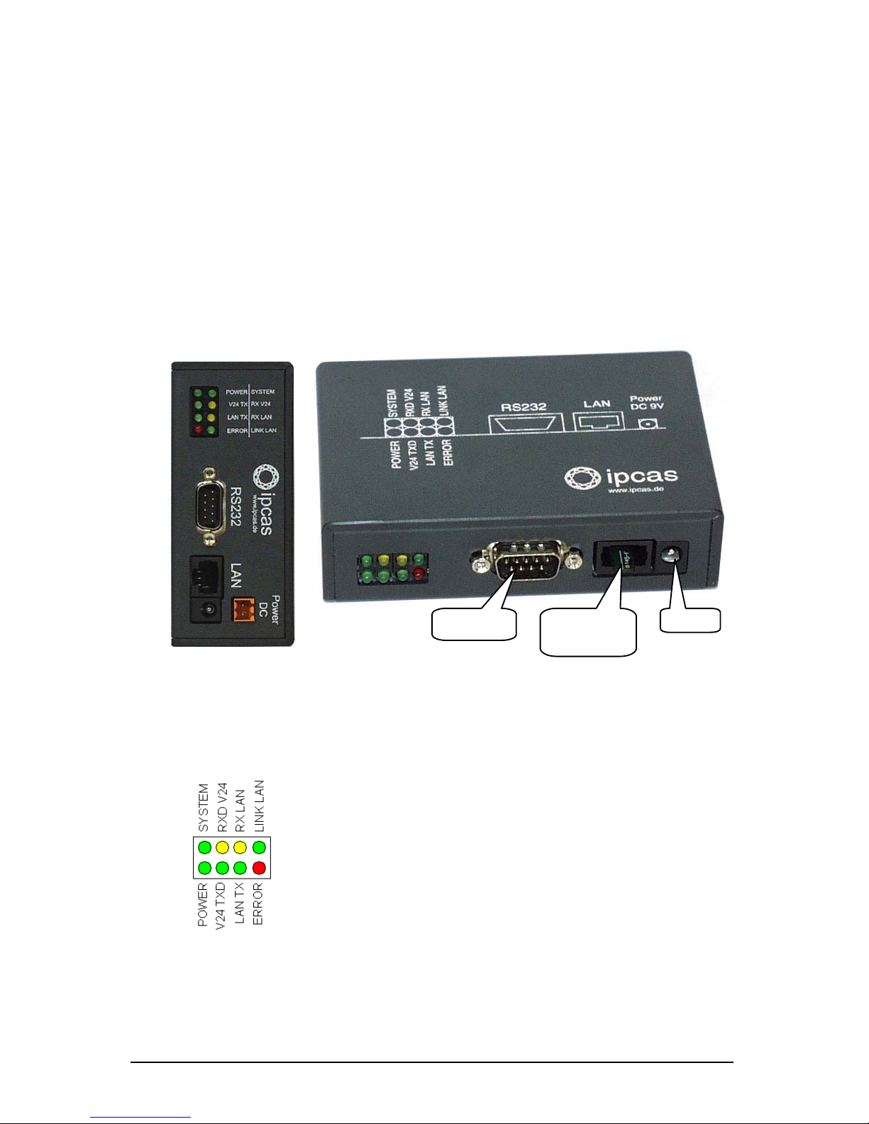
1.2 Sockets
i pE ther2 32 .M o dem ha s three socket s:
· Ethernet (10BaseT) for a 10/100 Mbit network
· RS232 SUB-D 9
· 9V DC powe r suppl y
A diagram of all connectors and their designation is displayed on the housing.
The LEDs indicate the device state and have the following meaning:
· POWER The device is switched on.
· System Slow flashing indicates that at the moment there is no
connection to a PC. Fast flashing indicates that the
device is in use.
· LINK LAN There is a physical link to the network.
· LAN Rx Packets are received via the Ethernet.
· LAN Tx Packets are sent to the Ethernet.
· V24 Rx Data is received via the RS232 line.
· V24 Tx Data is sent via the RS232 line.
· Error Errors have occured in the RS232 line.
RS232
SUB-D 9 Pin
Ethernet
10/100
RJ45
9V DC
Page 9

Subject to modif ic ations Last Update 22. 10. 03
ipcas GmbH ipEther232.Modem V6.01 Page 9 of 44
Chapter2: Commissioning the ipEther232.Modem
2.1 Commissioning
Connect the device to the mains. The "Power" signal and the flashing "System"
LED indicate that ipEther232 is ready for operation.
ipEther232 is connected to the network via an RJ45 socket.
The "Link LAN" LED (connection) indicates the connection to the LAN.
If this is not the case, check the netwok connection or network line.
The enclosed CD contains a modem driver set-up program and the configuration
tool. The modem driver runs on all windows NT based operating systems, as well
as Windows NT 4 from SP5, Windows 2000 and Windows XP.
No PC reboot is necessary after installation. The configuration tool for configuring
the device starts automatically after installation.For later configuration sessions
the program is included in the "Programme-ipEther232.Modem" folder.
You can also set up your ipEther232.Modem with a serial configuration using AT
commands.
(for more details see chapter 2.6 Serial Configuration and chapters 3 & 4).
2.2 Set the IP Address
On delivery of ipEther232, no valid IP address has been set (Default: 10.10.5.1).
T o start wi th , each d e vi ce must b e allocat e d an un am bi gu ou s IP ad d re ss.
The IP address can be obtained from the network administrator. It must comply
with your network and cannot be assigned twice.
In order to set the IP address in your ipEther232, the device must be connected
to its own network se gment. If need be, connect the device via a "cross over"
cable to the PC.
The configuration program recognizes all devices in its own network segment,
even if they do not have a valid IP address. Double-click on the device entry to
call up a dialog, where you can enter a valid IP address and further
configurations.
Page 10
Subject to modif ic ations Last Update 22. 10. 03
ipcas GmbH ipEther232.Modem V6.01 Page 10 of 44
The entry "Stat e " has the follow ing meaning :
· "not found"
The device could not be located anymore. It is not connected, switched off or
has been connected after a router blocking the UDP Port 3497.
· "connected"
The device has been located and can be addressed via the entered IP
address.
· "connected via router"
The device has been located and installed after the router. The IP address
cannot be changed.
· "found but unreachable"
The device has been located in the own network segment, but could not be
accessed via the entered IP address. Check whether the entered IP address
is valid for your network.
· "in use"
The device is in use at the moment. The parameters cannot be changed.
· “access denied“
Access wa s denied because password authentication has failed.
If ipEther232s are connected after a
router, they are not automatically
located. They have to be entered
manually ("Add Device manually“).
This is done by entering their IP
address. If the device can be
accessed via this address, it is
included in the list.
If the device is installed after a
router, the IP address cannot be
changed. This prevents the device
from becoming inaccessible by
accident.
Page 11
Subject to modif ic ations Last Update 22. 10. 03
ipcas GmbH ipEther232.Modem V6.01 Page 11 of 44
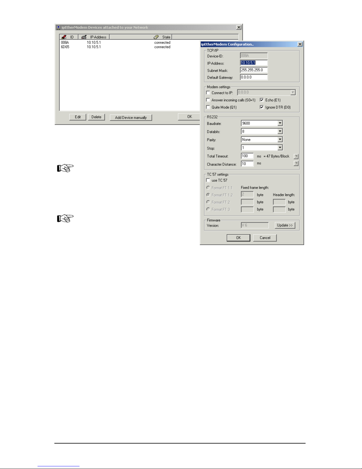
2.3 Configuration
As mentioned above, the configuration program recognizes all devices in its own
network segment.
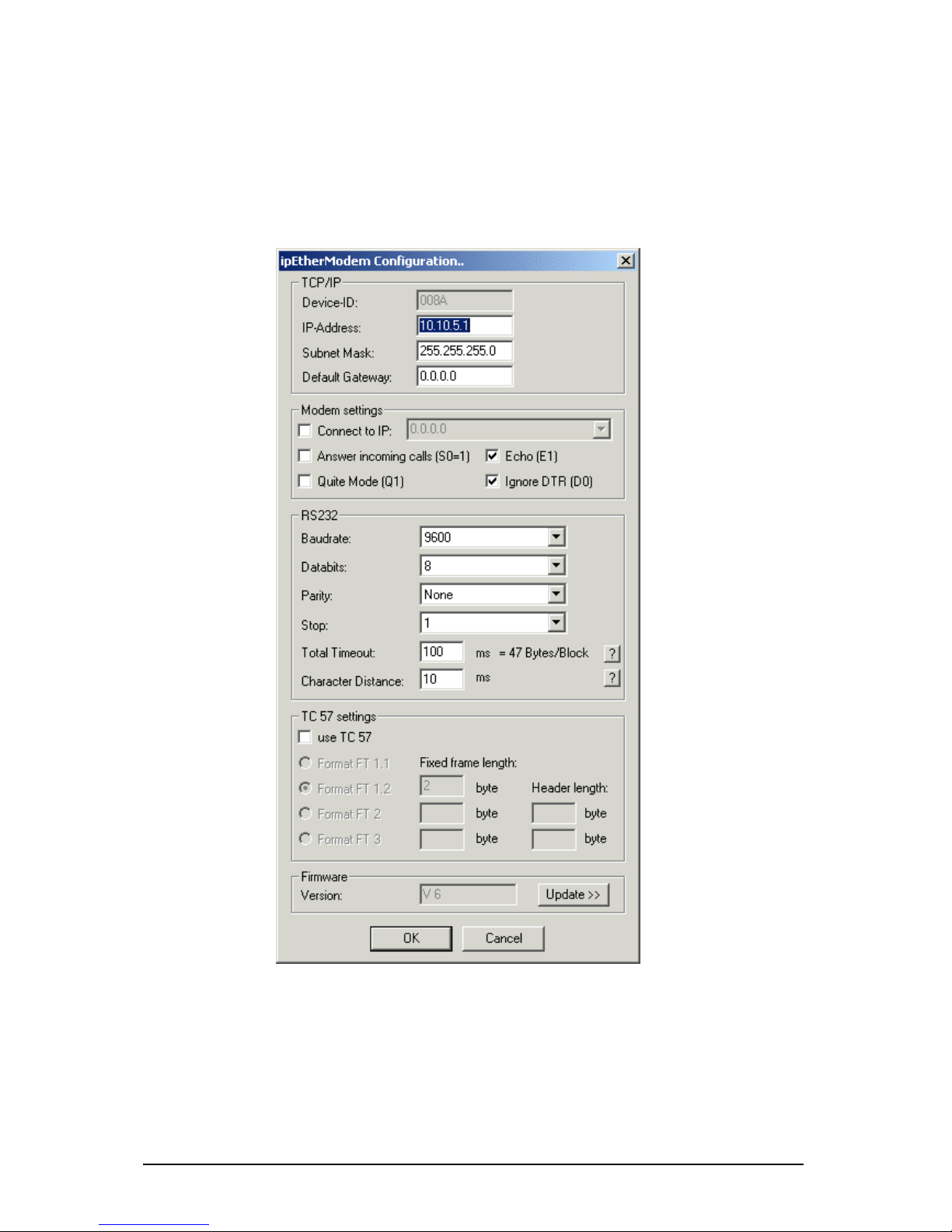
Double-click on an entry to open the detailed five-part dialog.
Page 12
Subject to modif ic ations Last Update 22. 10. 03
ipcas GmbH ipEther232.Modem V6.01 Page 12 of 44
TCP/IP:
This tells you the device ID, i.e. the ipEther232.Modem serial number and this is
where the network settings are configured.
Modem settings:
Here you can define the modem behavior.
"Connect to IP": Enter the IP address of the "communication partner" where a
connection is to be set up automatically (Leased line). After a connection breakoff there is an automatic attempt at restoring the link.
"Answer incoming calls": automatic call accept.
"Echo": command echo on.
"Quiet Mode": Re sult co de s on.
"Ignore DTR": ignore DTR status change.
RS232:
Baud rate, databits, parity and stopbits are adjusted to the communication
behavior of the serial terminal device.
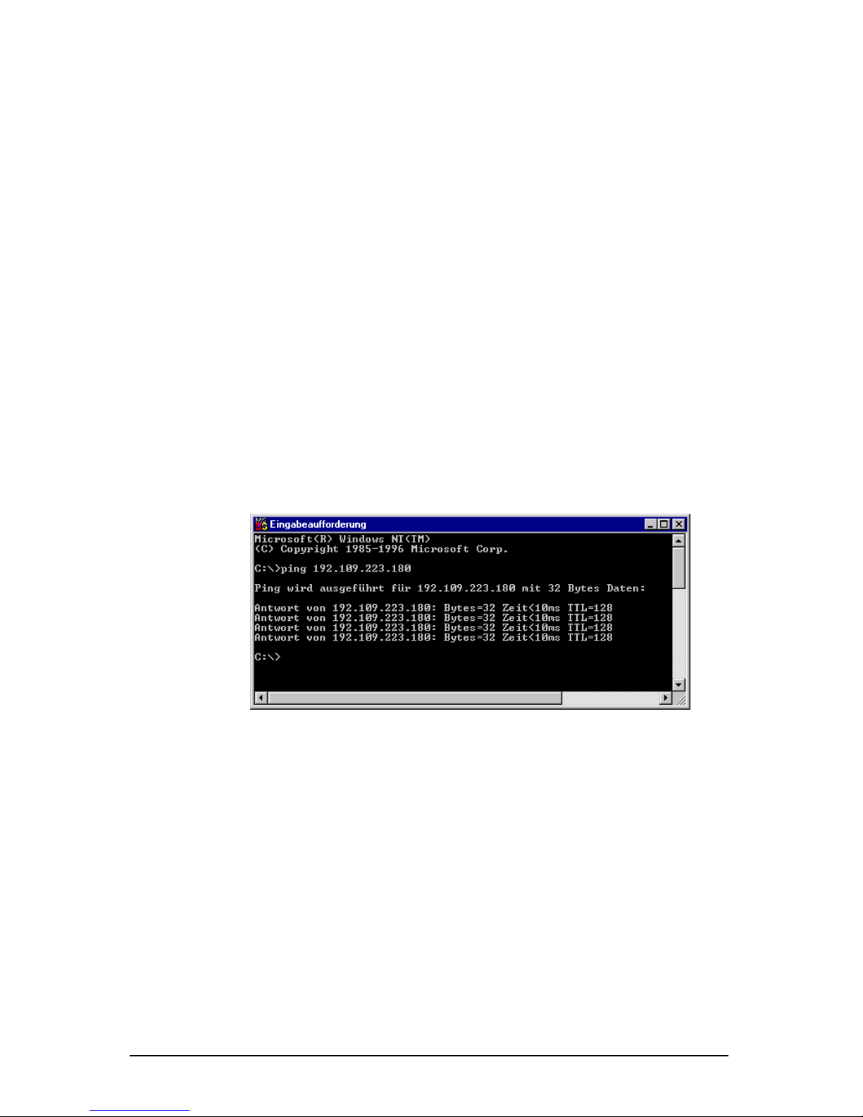
"Total Timeout": The default value of 50 ms applies to most cases. The "ping" tool
assist s in determining the ideal throughput time (see below).
"Character Distance" with a default value of 5 ms requires adjusting only in very
rare cases.
Throughput time + 10ms = ideal “To tal Tim eou t“
here < 10ms + 10ms = 20ms
Page 13

Subject to modif ic ations Last Update 22. 10. 03
ipcas GmbH ipEther232.Modem V6.01 Page 13 of 44
TC 57 se ttings:
The advantage of the TC 57 settings is that on reception of a frame of this
format (from the RS232 line) the frame is immediately sent on to the Ethernet
without having to wait for a timeout. This greatly improves communication speed
and performance.
The IEC 60870-5-1 and IEC 60870-5-2 norms define four standard frame
formats for the link layer. They are:
· Format FT 1.1
· Format FT1.2
· Format FT 2
· Format FT 3
The transmission frame formats - FT 1.2, FT 2 and FT 3 have a Frame of fixed
length.
The Frame with variable length for FT 2 and FT 3 have a header of fixed length.
It includes “Start character”, “Length” byte, “User Data” and “Check sequence”.
The user must select the desired Format and include values for “Fixed frame
length” and “Header length” parameters.
The range of “Fixed frame length” is from 2 to 255 bytes.
The range of “Header length” is from 2 to 14 bytes.
Firmware:
This tells you the firmware release. You can update to the most current version.
Page 14
Subject to modif ic ations Last Update 22. 10. 03
ipcas GmbH ipEther232.Modem V6.01 Page 14 of 44
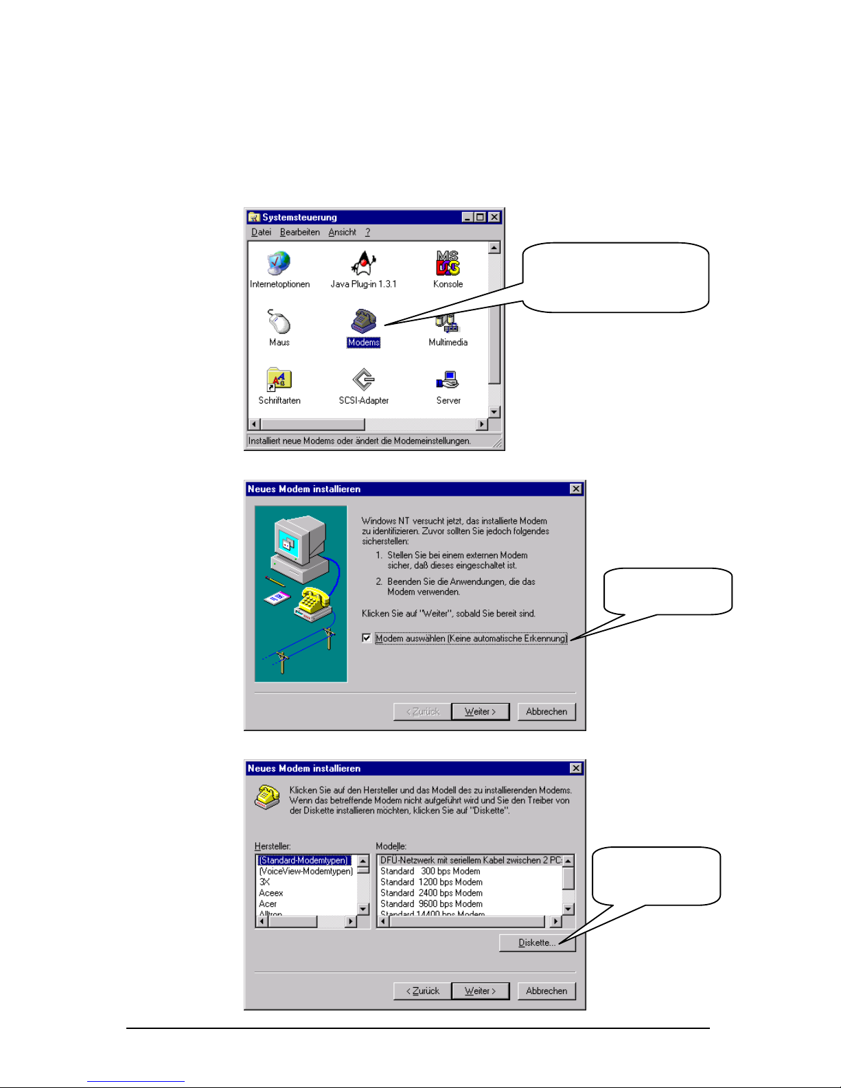
2.4 ipEtherModem.inf (Driver File)
Follow these instructions to install the mode m driver f or
ipEther232.Modem under Window s operating systems:
Cl i ck on " Cont rol Pa nel " in
the Explorer and then on
"Modems" to start the modem
i n stal lati on .
Check this option
fo r modem
i n stal lati on .
Select this option to
define the driver
location.
Page 15

Subject to modif ic ations Last Update 22. 10. 03
ipcas GmbH ipEther232.Modem V6.01 Page 15 of 44
Select "Browse"...
and enter the
location of the .inf
driver.
Click on
"Next"
Page 16

Subject to modif ic ations Last Update 22. 10. 03
ipcas GmbH ipEther232.Modem V6.01 Page 16 of 44
Enter the
i pE ther2 32 .M o dem
interface.
A
f t e r th e su c c e ssf u l
installation you can
adjust the modem to
your particular
requirements with
"Pro perties" and
"Dialing parameter"
Page 17

Subject to modif ic ations Last Update 22. 10. 03
ipcas GmbH ipEther232.Modem V6.01 Page 17 of 44
2.6 Serial Configuration
Connect the mains power supply to the device. The "power" light and the flashing
"system“ LED indicate that ipEther232 is operational.
The ipEther232 is connected to the PC or a serial terminal via a serial 1:1 cable.
(Basic settings: baud rate=9600, databits=8, parity=none, stopbits=1)
If the terminal tool, e.g. Hyperterm (in MS Windows to be found under Programs Accessories), is configured correctly for the connected Com port, the AT&V
command returns the current configuration of the Ethernet modem.
For more detailed explanations about the AT commands and the registers refer to
chapter 3 and 4.
Examples:
- Set the IP address: ATS100=192.109.223.242
- Set the baud rate to 38400: ATS31=5
- dial-up to the distant terminal: ATD 192.109.223.243
- hang up: +++ „2 sec. Pause“ ATH
- least line: ATS0=1, ATS102=192.109.223.243
(Configure distant terminal as well!!!)
Page 18

Subject to modif ic ations Last Update 22. 10. 03
ipcas GmbH ipEther232.Modem V6.01 Page 18 of 44
2.6.1 Configure Password Protection (Serial Devices only)
Enable the password configuration mode:
Enter the ATP master password to enter the configuration mode. The default
m a ste r passwo rd i s "0 00 00 0 “
à ATP000000
Set up and change the passw ords:
To change the master password, enter ATZ=“new master password". 9 more
passwords can be configured here (ATZ1...ATZ9).
à ATZ1=ipether
Each password consists of a maximum of 8 characters (additional characters are
ignored). The password is not case-sensitive (special characters are allowed).
Enter ATZ? or ATZ1?...ATZ9? to read out all the password s.
Enable pa ssword protection:
Register 81 allows you to enable and disable the password protection.
(only in the password configuration mode)
à ATS81=1 enable password protection mode
à ATS81=0 disable password protection
Passw ord blocking time:
Register S82 enables the setting of a password blocking time.
After three incorrect password entries, the modem waits for the blocking time,
before a new password query is allowed.
à ATS82=120 The blocking time is 2 minutes
Valid IP addresses:
The password configuration mode allows the configuration of ten IP addresse s,
for which calls are accepted. (ATR0....ATR9). If this l ist is empty, calls are
accepted from all partner modems.
à ATR1=192.168.10.12 Calls are accepted
Save changes:
All changes only take effect after they have been saved.
The AT&W command starts the saving process.
à AT & W
If the master password has been forgotten, the device must be sent in.
If the settings are not saved, all changes are lost, once the ipEther232.Modem is
disconnected from the power supply.
Quit the password configuration mode:
Enter ATP to exit the configuration mode.
à AT P
The dial-up to a password protected ipEther232.Modem returns the message
"PASSWORD:“
To set up a connection, the master password or one of the 9 additional
passwords (if defined) must be entered.
An incorrect entry leads to the "WRONG PASSWORD“ message.
If a call from an IP protected modem is not accepted, the message "ACCESS
DENIED“ is issued.
Page 19

Subject to modif ic ations Last Update 22. 10. 03
ipcas GmbH ipEther232.Modem V6.01 Page 19 of 44
Chapter 3: Control Commands
Up until now there has been no standardized AT command set (AT = command
prefix Attention), each manufacturer could implement his own. The V.250
command set is the first industry standard available. Microsoft recommends this
command set for the PC-98 specifications and makes it a mandatory requirement
for the PC-99 specifications.
With ipEther232.Modem you have purchased a state-of-the-art "Ethernet modem"
equipped with the AT command set. A terminal program enables you to enter the
AT commands (e.g. "Hyper Terminal": This tool is part of the MS Windows
package. You can find it under "Start - Programs - Accessories ".)
3.1 AT Command Input and E xecution
After power-up the Ethernet modem is ready for command input. Only in this
mode can commands be accepted, interpreted and executed.
All commands directed at the Ethernet modem must be prefixed with the ASCII
code AT or at (not permitted: At or aT) and be followed by "Enter". If several
commands are to be entered, they can each be entered with the AT prefix and
"Enter". It is just as permissible to place these commands in a single line between
an introductory AT and finish the command input with the "Enter" key.
For readability you might want to separate the individual commands with spaces.
On reaching the end of the command line buffer, no further character entry is
possible. The command line can however be edited with the "backspace" key or
executed by pressing "Enter".
3.2 Transmission Mode
After a successful connection setup to a distant terminal, the modem changes
from the command mode to the on-line data mode.
The on-line data mode implies that a connection to a distant data terminal (i.e.
another modem) has been established: The modem is on-line. This applies to a
successful connection setup (outgoing call/ dialing) as well as to the answering of
a call (call accept). In this mode data exchange (data transmission) between two
connected data terminals can take place.
3
To revert to command mode and back again while the connection is up, use the
Escape and ATO commands. The Escape command consists of a sequence of
three Escape characters (default setting: +++) and a valid command line.
Page 20

Subject to modif ic ations Last Update 22. 10. 03
ipcas GmbH ipEther232.Modem V6.01 Page 20 of 44
The Escape character is something completely different from the character of
the ASCII character set and can be changed with the S2 register.
After the three Escape characters have been entered, the modem switches to the
command mode. There is, however, no transmission interrupt before a valid
command line is recognized.
1. OnlineMode
2. +++ [2-Second pause]
3. CommandMode
4. ATO
5. OnlineMode
3.3 Quick Reference for AT Commands and Registers
This chart sorted by topic provides frequently used AT commands and registers
which enable you to modify the configuration of your Ethernet modem.
Configuration Commands Registers
Basic modem initialization AT&F
Controls the connection setup (dialing) ATD S37, S102
Call accept, line accept, hang up ATA, ATD, ATH, S0
Switch between command and on-line data mode +++, ATO S2
Read out modem information ATI, ATS, AT%V, AT&V
Employ stored initializations AT&F, AT&W
Controls the effect of DTR AT&D S37
Controls modem responses ATE, ATQ, ATV, AT&D S37
Controls serial speed ATB S31
Password protection ATP, ATZ S81, S82, S83
Call back AT R S110 – S119
Page 21

Subject to modif ic ations Last Update 22. 10. 03
ipcas GmbH ipEther232.Modem V6.01 Page 21 of 44
Chapter 4: Definition of AT Commands and
Registers
4.0 Chart of AT Commands
Hayes Commands
The Hayes command set (AT commands) has over time developed into an
industry standard among modem manufacturers. In addition, manufacturers use
specific modem commands for their different products. In part these commands
are not compatible with modems of other manufacturers.
ATA This command makes the modem go off-hook, in order to connect to the calling
remote modem. If no signal is recognized after a specified time, the modem
hangs up again.
ATB Query and set baud rate. à ATB returns current baud rate.
Assign baud rate (ATBval u e, 2400,4800,9600,19200,38400,115200 Baud)
à ATB2400 ...... à ATB115200
ATD Di ali ng functi on . AT Dipaddress (ATDP and ATDT are suppressed and executed
as AT D (P= pul se di al , T =tone dial )
à ATD192.109.223.4 à ATD192,109,223,4
à ATDP192.109.223.4 à ATDP192,109,223,4
à ATDT192.109.223.4 à ATDT192,109,223,4
ATE Command echo enable/ disable:
à ATE0 echo off à ATE1 echo on
ATH Modem goes on or off hook.
à ATH0 modem hangs up (goes on-hook), the connection is broken off. Only
possible in command mode. à ATH1 modem goes off hook (identical function to
ATO).
ATI Return product information.
à ATI0 2 (hardware code)
à ATI1 www.i p ca s.de (website)
à ATI2 ipEther.Modem (product name)
à AT I3 V1.7 14 . 04 .2002 (fi rm ware, date)
ATO Return to data mode. à ATO
Note: By entering +++ you can switch to command mode during a modem
connection, where AT commands can be executed. This does not break off the
connection. The ATO command terminates the command mode.
Page 22

Subject to modif ic ations Last Update 22. 10. 03
ipcas GmbH ipEther232.Modem V6.01 Page 22 of 44
ATP Enable and disable the password configuration mode of the modem.
After successful entry of the master password, password s can only be set at the
local RS232 interface. Password s have a maximum length of 8 characters and
their transmission is always in encrypted code. The password protection can be
switched on/off in the password configuration mode by setting the register 81
(ATS81=1 enable; default = off (ATS81=0)).
à AT P master password enable the password configuration mode
(default:“000000“ à ATP000000 )
à AT P q ui t the co nf ig u ration mo de
If the master password has been forgotten, the device must be sent in.
ATQ Enable / disable modem echo.
à ATQ0 send echo à ATQ1 no echo
ATR Ten IP addresses, for which calls are accepted, can be defined in the password
configurati on mode (ATR0....ATR9 (Register 110-119)). If this list is empty, calls
are accepted from any partner modem.
If a call from a modem is not accepted the "ACCESS DENIED“ message is
issued..
à AT Rnumber=value à ATR2=192.168.120.23
à AT R2 ? read out regi ste r
ATS Set and query the internal Ethernet modem registers.
Query: ATSregi ster? à ATS2? (Output "+" (default)
Set: ATSregister=value à ATS0=2 (i.e. the modem answers a call after 2 rings)
ATV Return system echo of modem as character string or digits.
à ATV0 response is a number à ATV1 response is a character string ("Ring",
"Connect", "Busy") (if echo is not disabled with ATQ1)
A further description can be found in chapter "4.2 Result Code “.
ATZ Change password s (only possible in the password configuration mode (see
ATP)).
Up to 9 password s may be saved in the Ethernet modem.
Password s consist of a maximum number of 8 characters, no difference is made
between small and capital letters (special characters are allowed).
à AT Z=master password (change maste r passwo rd (default:“000 000“))
à ATZ1=password ... AT Z9=password
à ATZ1? returns the defined password
Page 23

Subject to modif ic ations Last Update 22. 10. 03
ipcas GmbH ipEther232.Modem V6.01 Page 23 of 44
AT%V Re turn firmware version (eq ual s AT I3). à AT %V
AT&D Interpret DTR control line.
à AT&D0 ignore DT R ON/OFF transition
à AT&D1 In this case the DTR transi tion from ON to OFF has the following
effe cts: If the modem i s in comman d m ode , the transi tion has no effect. During a
connection setup, the DTR transition from ON to OFF breaks off the connection setup. If the modem is in on-li ne da ta mod e (i .e. the connection is se t up), i t swi tche s to
the command mode.
AT&F Load default configuration. Exception Register S99. à AT & F
Thi s command is not execut ed while there i s a conne ction .
AT&V Read out and display current configuration.
AT&W Store current configuration in flash.
à AT&W0 store configuration à AT&W1 store configuration
The following registers were not reset:
Register Definition
S1 Number of rings
S31 Baud rate
S32 Parity
S33 DataBits
S34 StopBits
S81 Password protection
S99 Time between two rings
S100 Own IP
S101 DefaultGateway
S103 SubnetMask
S104 MAC-Adress
S110-119 Valid IP addresses
Page 24

Subject to modif ic ations Last Update 22. 10. 03
ipcas GmbH ipEther232.Modem V6.01 Page 24 of 44
4.1 Register Chart
The modem has i nt e rnal regi sters, enabling you to modify it s con figu ration (see al so
ATS command).
Register Definition Default Options
S0 Auto answer 0 [0…9] rings
S1 Number of rings 0 Read only
S2 Escape Character + ASCII
S3 CR Character 0x0d ASCII
S4 LF Character 0x0a ASCII
S5 BS Character 0x08 ASCII
S30 Inactive Timer 0 [0..255] ms
S31 Baud rate 3 1=2400 2=4800 3=9600 4=19200
5=38400 6=57600 7=115200
S32 Parity 0 0=None 1=Even 2=Odd 3=Mark
4=Space
S33 DataBits 8 7=7 8=8
S34 StopBits 1 1=1 2=2
S35 Rxd Timeout 50 [5..255] ms
S36 Char Timeout 5 [5..255] ms 0=Off
S37 Bit options 7 [0..255] decimal value
S38 Use TC57 0 [0..1]
S39 TC57 type 1 [0..3]
S40 fixed frame length 2 [2..255]
S41 User data length 2 [2..14]
S81 Password protection 0 [0..1]
S82 Password blocking
time
3 [0..255] minutes 0=Off
S83 Wrong password entry 0 [0..255] in the RAM only
S99 * Time between two
rings
4 [0..255] s
S100 own IP 10.10.5.1 xxx.xxx.xxx.xxx
S101 DefaultGateway 0.0.0.0 xxx.xxx.xxx.xxx
S102 AutoRemote 0.0.0.0 xxx.xxx.xxx.xxx
S103 SubnetMask 255.255.255.0 xxx.xxx.xxx.xxx
S104 MAC address 00:09:8E:x:x:x Read only
S110 * Valid IP address 0.0.0.0 xxx.xxx.xxx.xxx
S111 * Valid IP address 0.0.0.0 xxx.xxx.xxx.xxx
S112 * Valid IP address 0.0.0.0 xxx.xxx.xxx.xxx
S113 * Valid IP address 0.0.0.0 xxx.xxx.xxx.xxx
S114 * Valid IP address 0.0.0.0 xxx.xxx.xxx.xxx
S115 * Valid IP address 0.0.0.0 xxx.xxx.xxx.xxx
S116 * Valid IP address 0.0.0.0 xxx.xxx.xxx.xxx
S117 * Valid IP address 0.0.0.0 xxx.xxx.xxx.xxx
S118 * Valid IP address 0.0.0.0 xxx.xxx.xxx.xxx
S119 * Valid IP address 0.0.0.0 xxx.xxx.xxx.xxx
* Registers are not issued with AT&V
Page 25

Subject to modif ic ations Last Update 22. 10. 03
ipcas GmbH ipEther232.Modem V6.01 Page 25 of 44
S0 Automatic Call Accept
Ra n ge 0..9 rings
Default 0
Sto re in pe rm anen t m emory AT&W
In the S0 register, you can set the automatic call accept (auto answer). If S0 > 0,
each incoming call is automatically answered. The value in S0 defines the
number of rings the modem waits before it auto answers.
If the entered value is not within the valid range, the modem automatically enters
the next possible value (minimum or maximum value) defining the number of
rings the modem waits. If, for instance, you enter 10 in Germany, the modem
automatically enters 9.
S1 Ring Counter
Range 0..255 rings
Default 0
Store in permanent memory no
The S1 register contains the number of rings of an incoming call. The value in S1
is reset to zero, if no rings have arrived for a time span specified in the S99
register (default 5 seconds). During this time new incoming calls cannot be
di stingui shed and t h e mo de m ca nn ot di al .
S2 Escape Code Character
Range 0..255 decimal
Defa ult 43 (+)
Sto re in pe rm anen t m emory AT&W
In the S2 register, you can define the Escape command '+++', allowing you to
switch from data mode to command mode.
Values equalling 0 or >128 block the switchover to the command mode.
S3 Carriage Return Cha racter
Range 0..127 decimal
Defa ult 13 (Carria ge Return )
Sto re in pe rm anen t m emory AT&W
In the S3 register, you can define the Return character.
S4 Linefeed Character
Range 0..127 decimal
Default 10 (Linefeed)
Sto re in pe rm anen t m emory AT&W
The S4 register defines the linefeed character.
Page 26

Subject to modif ic ations Last Update 22. 10. 03
ipcas GmbH ipEther232.Modem V6.01 Page 26 of 44
S5 Backspace Character
Range 0..32, 127 decimal
Default 8 (Backspace)
Sto re in pe rm anen t m emory AT&W
The S5 register defines the Backspace character.
S30 Inactive Timer
Range 0..255 (10 seconds)
Default 0 (timer off)
Sto re in pe rm anen t m emory AT&W
In the S30 register, you can set the time span the modems waits before it kills the
connection automatically, if there has been no reception or transmission of data
in the meantime. 0 disables the inactive timer.
S31 Baud Rate
Range 1..7
De faul t 3 ( = 96 00 Baud)
Sto re in pe rm anen t m emory AT&W
In the S31 register, you can set the Baud Rate. The baud rate defines the
number of state changes of the transmitted signal per second.
(1=2400 2=4800 3=9600 4=19200 5=38400 6=57600 7=115200)
S32 Parity
Ra n ge 0..4
Default 0 (no parity)
Sto re in pe rm anen t m emory AT&W
In the S32 register, you can set the parity bit for error detection in the case of
asynchronous data transmission. Part of the data transmission format.
Occasionally no parity, constantly one (mark) or zero (space). Even parity means
that the bit is set, if the data bit number is even and vice versa for odd parity.
0=None 1=Even 2=Odd 3=Mark 4=Space
S3 3 Data Bits
Ra n ge 7..8
Default 8
Sto re in pe rm anen t m emory AT&W
In the S33 register, you can set the number of data bits.
7=7 Bits 8=8 Bits
Page 27

Subject to modif ic ations Last Update 22. 10. 03
ipcas GmbH ipEther232.Modem V6.01 Page 27 of 44
S34 Stop Bits
Ra n ge 1..2
Default 1
Sto re in pe rm anen t m emory AT&W
In the S34 register, you can set the number of stop bits. One or two bits in
asynchronous transmission, indicating the end of a data word (packet).
1=1 Stop Bit 2=2 Stop Bits
S35 Rxd Timeout (Total Read Timeout)
Range 5..255 ms
Default 50 ms
Sto re in pe rm anen t m emory AT&W
In the S35 register, you can set the Total Read Timeout.
After the first byte has been received, "Total Read Time" starts. After it has
expired, all characters received so far are sent to the PC. This value must not be
lower than the delay of the UDP packet in the Ethernet. You can use the "ping"
tool to determine the throughput time.
S36 Char Timeout (Character Distance)
Range 5..255 ms
Default 5 ms
Sto re in pe rm anen t m emory AT&W
In the S36 register, you can set the Character Distance.
If the time span between two received characters (bytes) is greater than the
defined Character Timeout, all bytes received so far are sent to the Ethernet.
Page 28

Subject to modif ic ations Last Update 22. 10. 03
ipcas GmbH ipEther232.Modem V6.01 Page 28 of 44
S3 7 Bit O ptions
Range 0..255
Default 5 (binary: 0000 0101)
Sto re in pe rm anen t m emory AT&W
In the S37 register, you can set the bit options Echo, Quiet, DTR and Verbose.
Bit Effect Default Definition
2^7 n/c 0
2^6 n/c 0
2^5 n/c 0
2^4 Q0 / Q1 0 Echo (Return code) on/off(see
ATQ)
2^3 n/c 0
2^2 &D0 / &D1 1 DTR control line (see AT&D)
2^1 V0 / V1 0 System return code (see ATV)
2^0 E0 / E1 1 command echo (see ATE)
00000101 binary = 5 decimal
S38 UseTC57
Ra n ge 0..1
Default 0
Sto re in pe rm anen t m emory AT&W
The advantage of the TC 57 settings is that on reception of a frame of this format
(from the RS232 line) the frame is immediately sent on to the Ethernet without
having to wait for a timeout. This greatly improves communication speed and
performance.
(Default = 0, this means the registers 38-41 are inactive; 1 = register 38-41
active).
S39 TC57 type
Range 0..3
Default 1
Sto re in pe rm anen t m emory AT&W
The IEC 60870-5-1 and IEC 60870-5-2 norms define four standard frame
formats for the link layer. They are:
· Format FT 1.1
· Format FT1.2
· Format FT 2
· Format FT 3
The transmission frame formats - FT 1.2, FT 2 and FT 3 have a Frame of fixed
length.
The Frame with variable length for FT 2 and FT 3 have a header of fixed length.
It includes “Start character”, “Length” byte, “User Data” and “Check sequence”.
The user must select the desired Format and include values for “Fixed frame
length” and “Header length” parameters.
Page 29

Subject to modif ic ations Last Update 22. 10. 03
ipcas GmbH ipEther232.Modem V6.01 Page 29 of 44
S40 TC57 Fixed frame length
Range 2..255
Default 2
Sto re in pe rm anen t m emory AT&W
The range of “Fixed frame length” is from 2 to 255 bytes.
S41 TC57 User data length
Range 2..255
Default 2
Sto re in pe rm anen t m emory AT&W
The range of “Header length” is from 2 to 14 bytes. This value only refers to "user
data" from the header.
S81 Password protection
Range 0..1
De fa ul t 0
Sto re in pe rm anen t m emory AT&W
Register 81 allows enabling and disabling the password protection.
The default value is 0 (password protection inactive).
If the password protection has been enabled the modem displays the following
behavior:
§ After dial-up the modem issues the "PASSWORD:“ message. The user has
three trials to enter the password correctly. Then the modem is blocked for a
definable time (see S82 in minutes)
§ Incorrect password entries are counted (in the RAM only) ATS83.
§ DCD i s only activated in the remote modem after a successful password entry.
After three incorrect password entries the remote modem goes on-hook without
any call-back. "NO CARRIER“ appears.
S82 Password blocking time
Range 0..255
De fa ul t 3
Sto re in pe rm anen t m emory AT&W
The blocking time is set in register 82. After three incorrect password entries the
modem allows no further password request until the blocking time is up. (0 =
function disabled).
S83 Incorrect password entries
Range 1 Byte
De fa ul t 0
All incorrect password entries are counted in register 83 (in the RAM only).
Page 30

Subject to modif ic ations Last Update 22. 10. 03
ipcas GmbH ipEther232.Modem V6.01 Page 30 of 44
S99 Time Distance between rings
Range 10..255
De faul t 4 (4 seco nd s)
Sto re in pe rm anen t m emory AT&W
In the S99 register, you can set the maximum permissible time distance between
two received rings. The default value of 7.5 seconds applies to most cases.
S100 IP Address
Range xxx.xxx.xxx.xxx
Default 10.10.5.1
Sto re in pe rm anen t m emory AT&W
In the S100 register, you can set your own IP address. The factory-set value of
10.10.5.1 must be adjusted to your network.
Bear in mind, when modifying this value, that it cannot be chosen freely, but
depends on the network address of the TCP/IP network. The input format follows
the familiar syntax (e.g. 192.168.31.5).
S1 01 Default Gateway
Range xxx.xxx.xxx.xxx
Default 0.0.0.0
Sto re in pe rm anen t m emory AT&W
In the S101 register, you can set the Default Gateway. Here you enter the
Gateway IP address, if connections to other subnetworks are to be established.
S1 02 Auto Re mote
Range xxx.xxx.xxx.xxx
Default 0.0.0.0
Sto re in pe rm anen t m emory AT&W
In the S102 register, you can set the Auto Remote Partner. Enter the IP address
of the "communication partner" for which a connection is to be established
automatically (Leased line). After a connection break-off there is an automatic
attempt at restoring the connection. The connection set-up and take-down can be
controlled via DTR (see AT&D).
S103 Subnet M ask
Range xxx.xxx.xxx.xxx
Default 255.255.255.0
Sto re in pe rm anen t m emory AT&W
In the S103 register, you can set the Subnet Mask. The Subnet Mask only needs
to be entered if the IpEther232.Modem is to connect to another subnetwork. In
this case enter the Subnet Mask for the subnetwork where the ipEther is located
(e.g. 255.255.255.0). Please note: The IP address also defines the network class.
This results in a Default Subnetmask (e.g. 255.255.0.0 for a Class B network).
They can only be extended "towards the right".
Page 31

Subject to modif ic ations Last Update 22. 10. 03
ipcas GmbH ipEther232.Modem V6.01 Page 31 of 44
S1 04 M AC Address
Range 00:09:8E:xx:xx:xx
This register contains the Mac address of the network interface, which cannot be
changed.
S110-119 Valid IP Addresses
Range xxx.xxx.xxx.xxx
Default 0.0.0.0
Sto re in pe rm anen t m emory AT&W
In register 110 to 119 IP addresses can be set for which a call is accepted. If no
register contains an IP address, all calls are accepted.
If a call is not accepted by a modem, the "Access Denied“ message is shown.
4.2 Result Code
System return code as a character string or digits (see AT command ATV), if not suppressed with
ATQ1.
Char string Digit Definition
OK 0 Command line processed
CONNECT 1 Successful connection setup
RING 2 Incoming call
NO CARRIER 3 No connection established or inactivity
timer expired
ERROR 4 Error in command input
NO DIALTONE 6 No Ethernet connection
BUSY 7 Dialed line busy
ACCESS DENIED 8 Call rejected due to failed password
authentication
Password 11 Password OK
Wrong Password 12 Wrong Password
Page 32

Subject to modif ic ations Last Update 22. 10. 03
ipcas GmbH ipEther232.Modem V6.01 Page 32 of 44
Chapter 5: Technical details
Great emphasis was placed on compatability during device design.
Due to the Ethernet, there are, however, some minor restrictions.
· Data is not transmitted in bytes to the network, but Ethernet blocks are
formed. This might result in minor delays.
· The blocking function does not directly affect the application, but might
help to reduce the network load.
· Some fine-tuning might be necessary for time critical applications as well.
This involves the two timeout parameters ("Total Read Timeout",
"Character Distance").
Block formation for serial data before transmission into the Ethernet
After the first byte arrives, "Total Read Time" starts. After the time expires, all
characters received so far are relayed to the Ethernet. The default value is 50
ms.
"Character Distance" is the maximum distance between two received characters.
If this is exceeded, all characters received so far are transmitted to the Ethernet.
T he de fa ul t valu e i s 5 m s.
UART
The UART supports transmission speeds between 2400 baud and 115200 baud.
Higher baud rates might result in data loss, if data is transmitted continuously.
7 or 8 data bits can be used.
The parities "none", "even", "odd", "1" and "0" are supported.
7-bit data does not support the parity "none".
Page 33

Subject to modif ic ations Last Update 22. 10. 03
ipcas GmbH ipEther232.Modem V6.01 Page 33 of 44
5.1 Specifications
Et hernet
10BaseT, 10/ 100 Mbit, RJ45 Interf ace
TCP/IP
UDP Port 3497
ICMP
ARP
Fir mw ar e
Updatable w ww .ipcas.de
RS232
DB9 Interface, full modem occupancy
Baud: 2400 to 115200
Par ity: None, Even, Odd, Mark, S pace
Data: 7 or 8 Bits
Stop: 1 or 2 Bits
RS485
4 Pin connector
Send signal optional (RTS or DTR)
Display:
Pow er, System, Error
Link, EthRxD, EthTxd
Rs232 RxD, TxD
Pow er Supply
Over 9 V olt mains plug. - 9 V olt DC.
Optional: 18V - 72V AC / DC w ith polarity protection.
80 mA max .
Driver
Setup & conf iguration file f or Window s NT4 / 2000 / X P
Page 34

Subject to modif ic ations Last Update 22. 10. 03
ipcas GmbH ipEther232.Modem V6.01 Page 34 of 44
5.2 Pin Assignment
S ERIAL PORT
9Pin S ocket
Pin Direction Definition
1 OUTPUT DCD Data Carrier Detect
2 OUTPUT RXD Receive Data
3 INPUT TXD Transmit Data
4 INPUT DTR Data Terminal Ready
5 GND Ground
6 OUTPUT DSR Data Set Ready
7 INPUT RTS Request To Send
8 OUTPUT CTS Clear To Send
9 OUTPUT RI Ring Ind icator
RS485
S ERIAL PORT
9Pin Plug
Pin Direction Definition
1 NC
2 OUTPUT TX+ (Send data)
3 OUTPUT TX- (Send data)
4 NC
5 GND Ground
6 INPUT RX+ (Receive Dat a)
7 INPUT RX- (Receive Data)
8 NC
9 NC
Ethernet connector
RJ 45
Pin Na m e Description
1 TX+ Transceive Data+
2 TX- Transceive Data-
3 RX+ Receiv e Data+
4 n/c Not used
5 n/c Not used
6 RX- Receive Data-
7 n/c Not used
8 n/c Not used
Page 35

Subject to modif ic ations Last Update 22. 10. 03
ipcas GmbH ipEther232.Modem V6.01 Page 35 of 44
5.2.1 Pin Assignment ipEther232.Modem OEM
ipEther V2.1 Pin assignment for interfaces:
Page 36

Subject to modif ic ations Last Update 22. 10. 03
ipcas GmbH ipEther232.Modem V6.01 Page 36 of 44
J1: LAN interface
1 TX+ 3 RX+
2 TX- 6 RX-
J4: RS232 / RS485 interface
1 CD / - 6 DSR / RX+
2 RXD / TX + 7 R TS / RX3 TX D / TX- 8 CTS / 4 DTR / - 9 RI / 5 GND/GND
J6: LAN interface (OEM)
1 TX+ 3 RX+
2 TX- 4 RX-
J7: LED interface (OEM)
1 +5V 6 LED_LA N_RXD
2 LED_POWER 7 LED_LAN_TXD
3 LED_SYSTEM 8 LED_SYSTEM2
4 LED_COM_TXD 9 LED_LAN_LINK
5 LED_COM_RXD 10 GND
J8: Module interf ace
1 CD 6 RTS / RX2 DSR / RX+ 7 TX D / TX3 RX D / TX + 8 DTR
4 CTS 9 DTR_TTL
5 RI
J9: Module interf ace
1 +5V 6 CTS_TTL
2 GND 7 RI_TTL
3 CD_TTL 8 RTS_TTL
4 DSR_TTL 9 TXD_TTL
5 RX D_ T TL
J10: RS232 / RS485 interf ace (OEM)
1 CD / - 6 CTS / 2 DSR / RX+ 7 D T R / -
3 RXD / TX+ 8 RI / 4 RTS / RX- 9 GND
5 TXD / TX- 10 n/c
JP6: Supply voltage input (OEM)
1 GND 2 Vin+ (8 – 14 VDC)
JP7: 5V Supply voltage input (OEM)
1 GND 2 +5V
Page 37

Subject to modif ic ations Last Update 22. 10. 03
ipcas GmbH ipEther232.Modem V6.01 Page 37 of 44
5.2.2 Power supply units
(18-36 V AC / DC or 18-72 V AC / DC with polarity protection)
Remove all 4 jumpers (JP6 & JP7) and mount power supply
unit with spacer and fastening screw.
Page 38

Subject to modif ic ations Last Update 22. 10. 03
ipcas GmbH ipEther232.Modem V6.01 Page 38 of 44
5.2.3 RS232.Modem Module
This manual refers to the ipEther232.Modem
together with the module shown here.
No optional settings.
5.2.4 RS232 Module
T he i pEt her2 32 m anual ref e rs to ipEther togeth er
with the displayed module, they are mentioned here
to complete the li st.
No optional settings.
Page 39

Subject to modif ic ations Last Update 22. 10. 03
ipcas GmbH ipEther232.Modem V6.01 Page 39 of 44
5.2.5 RS485 Module
Together with this module, the ipEther232 user guide refers to ipEther with an
RS485 interface, they are mentioned here to complete the list.
The transmitter of RS485 can either be used in continuous operation, e.g. for
point-to-point connections, or it can be triggered by software. This option is
enabled by jumpers.
The factory setting is continuous operation.
Br. 3
Br. 2
Br. 1
Jumper J 1 J 2 J 3
Transmitter in continuous
operation
- - X
switch on by DTR X - switch on by RTS - X -
X = closed
- = open
3.2.6 RS485 as a 2 Wire solution
For the pin allocation please refer to chapter 5.2 Pin allocation.
RS485 Module
RX-
TX-
RX+
TX+
RX-
TX-
RX+
TX+
Page 40

Subject to modif ic ations Last Update 22. 10. 03
ipcas GmbH ipEther232.Modem V6.01 Page 40 of 44
-
Scale: 1 : 1
5.3 Measurements
General Tolerances
Date Name
Mod.. 15. 03. 02 P. Fel bi ng er
Appr..
1.00
9
Page
ipEther232 (OEM V1)
Creat. by
P.
Cr eated b y:
St. Modificatio n Date Name Orig .
6,2
8,8
1,5
8,0
12, 5
13, 0
15,2
30,8
18,4
11, 5
14, 0
15,1
51,0
77,7
90,7
2,0
4,0
2,0
6,0
69, 1
100,0
RS232 DB9 Socket
Ethernet Connector
10Base T ( RJ45)
Po we r Supply
Diagnosis Panel with 8 LEDs:
POWE
R
V24 T X
D
LAN T
X
ERRO
R
SYSTEM
RXD V24
RX LAN
LINK LAN
Subjec t t o modi fi c ations
Circuit Board
Page 41

Subject to modif ic ations Last Update 22. 10. 03
ipcas GmbH ipEther232.Modem V6.01 Page 41 of 44
Page 42

Subject to modif ic ations Last Update 22. 10. 03
ipcas GmbH ipEther232.Modem V6.01 Page 42 of 44
Page 43

Subject to modif ic ations Last Update 22. 10. 03
ipcas GmbH ipEther232.Modem V6.01 Page 43 of 44
5.4 Declaration of EEC Compliance
EEC Compliance
is assured for the following product:
IpEther232
This company confirms that the product complies with the main specifications for the
protection against harmful interference laid down in the Council Guidelines on Harmonizing
the Statutory Regulations of the Member Stat es for Electroma gnetic Compatibilit y
(89/336/EEC).
Any modifications to ip Ether232 not authorized by this company invalidates this declaration.
This product was tested and evaluated for electromagnetic compatibility in accordan ce wit h
the following standards:
EN 55022/1998
EN 50082-2/1997
Place/Date/M anufacturer's Signature: Erlangen, 09 April 2002
Title of the Undersigned: Managing Director, Dipl.-Ing. Suganda Sutiono
Page 44

Subject to modif ic ations Last Update 22. 10. 03
ipcas GmbH ipEther232.Modem V6.01 Page 44 of 44
5.5 Glossary
ARP Address Resolution Protocol
bps Bits per second (also known as the baud rate)
CTS Clear to Send
DHCP Dynamic Host Configuration Protocol
DSR Data Set Ready
DTE Data Terminal Equipment
DTR Data Terminal Ready
HTTP HyperText Transfer Protocol
ICMP Internet Control Message Protocol
IEEE Institute (of) Electrical (and) Electronic Engineers
IP Internet Protocol
LAN Local Area Network
MAC Media Access Control
PC Personal Computer
RTS Request to Send
SNMP Simple Network Management Protocol
TCP Transmission Control Protocol
TFTP Trivial File Transfer Protocol
UDP User Datagram Protocol
Contact
ipcas GmbH
Wetterkreuz 17 Telef ax +49 9131 7677 78
D-91058 Erlangen Int ernet http:// www.ipc as.de
Telefon +49 9131 7677 0 E-Mail info@ipcas .de
 Loading...