

Page 1
Statement
Copyright © 2018 IPCamPower.com
Thi s docum ent con tains pro pr iet ar y inf or mat io n that is p ro tec te d by co py rig ht . No pa rt of thi s docum ent may b e
rep roduc ed, tra nsmit ted, tr anscr ibed, s tored i n a retri eval sy stem, o r trans lated i nto any lan gu age , in a ny fo rm
or by a ny mean s, electr on ic, m ec han ic al, m ag net ic, opt ical, c hemic al, man ual or othe rw ise w it hou t th e pri or w ritte n
per missi on of Our c ompan y.
USER GUIDE
PoE & O pti c a l Tr a n sm i ss i o n
PoE Switch
Product overview
Product Introduction
IPCP-4P2G-AF2 PoE Switch was designed specifically for IP cameras that utilize the standard PoE power type of
802.3af. This is a great PoE switch for systems utilizing 4 cameras or less. However, this PoE switch can be used to
power any type of device that uses standard PoE power such as IP phones, Wireless access points, and other
devices that use the 802.3af/at standard.
Feature
Complies to IEEE802.3af/at standards.
4 10/100 PoE powered Ports with 2 additional 10/100 non-powered uplink ports.
All the ports support Auto MDI/MDIX.
Each PoE port support Power up to 30 Watts with a total budget of 65 Watts for the entire switch
Support IEEE802.3x Full Duplex flow control and Duplex back pressure flow control function
Automatic MAC address learning and updating.
4K MAC Address
16G Broadband and 192Kb forwarding memory.
High performance full load power configuration.
LED indicator monitor working status and help fault detection
The i nform ation a nd produc t sp eci fi cat io ns wi th in this d oc ume nt a re su bj ect t o ch ange at a ny t ime , wi tho ut n oti ce
and w ithou t oblig ation to no ti fy an y pe rso n of s uch c ha nge.
Packing List
1 PoE switch
1 Power Cord / Adapter
1 Mounting Kits
1 User Guide
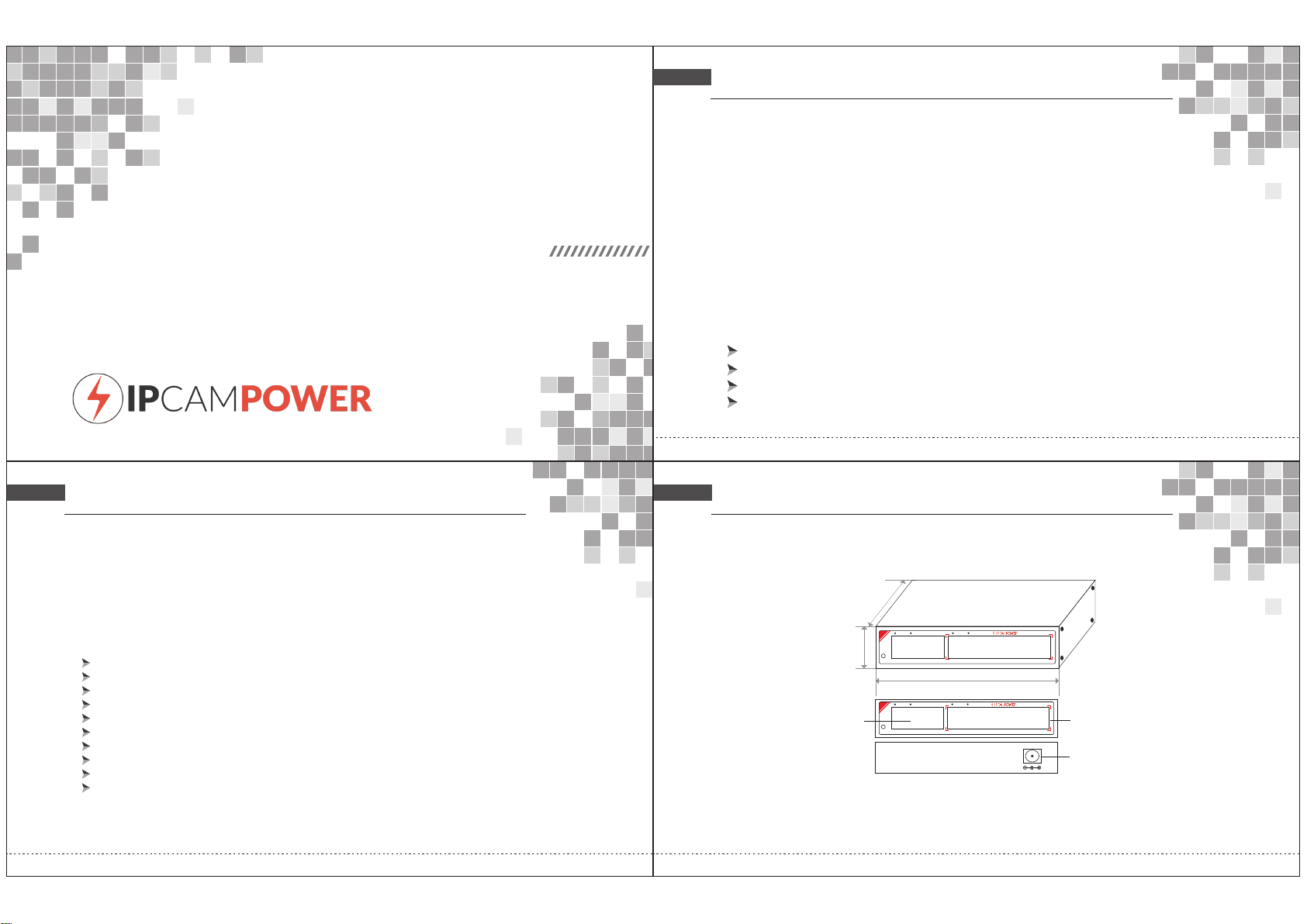
Technical Structure and Port Description
89mm
PoE
LINK
SPD
25mm
LINK
PWR
1 2
3 4 5 6
118mm
PoE
LINK
SPD
LINK
A
PWR
1 2
A.PoE p or t B. Up li nk C. DC 48-5 2V
3 4 5 6
10/100M P oE Swit ch
10/100M P oE Swit ch
POWE R
B
C
Page 2
Indicator description:
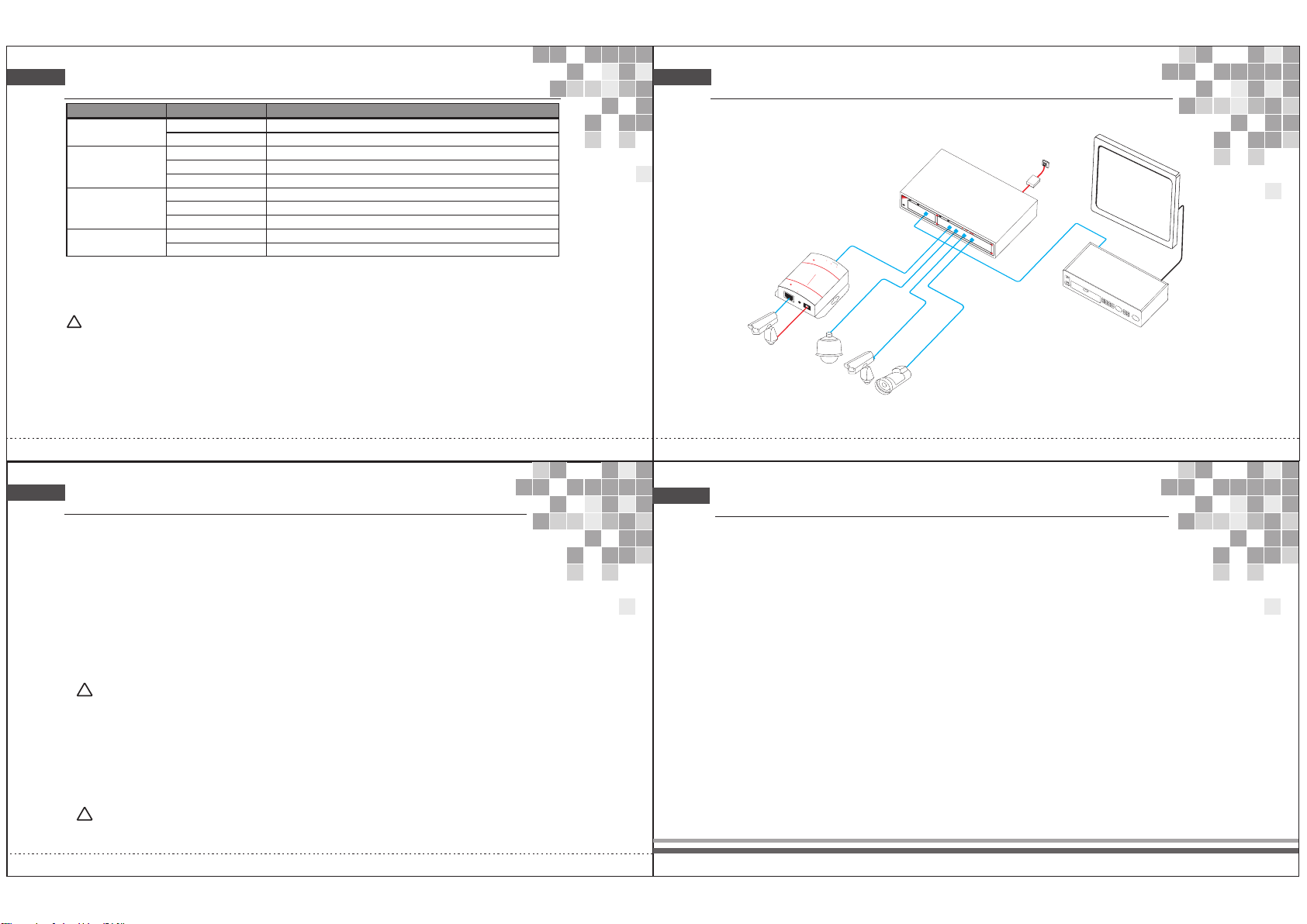
Connection Diagram
Ind icato r
Pow er indi cator : P
PoE I ndica tor: Po E
Sta tus
Gre en LED ON
Gre y
Gre en LED ON
Nor mal Pow er Supp ly
Pow er OFF
Con necte d PD Device , wo rki ng p rop er ly
Gre en LED Bl ink Sho rt circ uit or cu rrent o verlo ad
Des cript ion
OFF No Co nnected P D or P owe r OF F
Lin k indic ator: L ink
Yel low LED Bli nk
Yel low LED ON
Dat a trans missi on proper ly
Con necte d with 10Mb ps , 100 Mb ps PD
OFF No co nnected P D
Rat e indic ator: 1 00M
!
Note
Gre en LED ON
Gre en LED OF F
Wor king in 1 00M rate mo de
Do no t work in 1 00M rate mo de
Please confirm that the PD devices are complying with IEEE802.3af standard.
PoE Priority:
sorted by priority; Port 1, Port 2, Port 3, etc. then the power supply of lowest priority will be turned off.
Power Plug / Adapter:
PoE Port Indicator Lights:
Network Traffic Indicator Lights:
at an appropriate rate.
This function will protect the switch when it is overloaded, if all devices consumption are higher than specified, switch ports will be
Please only use the included power supply as the switch may be damaged if mismatched power is applied.
There are indicator lights on the front panel that will show you if the switch is supplying power to a PoE capable device.
There are lights on the front panel that will show if your plugged in device is transmitting / receiving network data
Installation guide
Please inst al l wi th t he s up porting devic es .
Installation
Please confirm the following things before installation:
1 If the POE ports power meets the power requirements of the connecting devices.
2 If th e POE sta ndard r equir ement and p ow er su pp ly ma tc h wit h th e power r ec eiv in g dev ic e,
“1/2+、3/6-(End-span).
3 If th e outpu t power o f the sup porting p ow er ad ap ter i s co nsi st ent wit h th e spe ci fic at ion i n th e label o f th e POE s wi tch .
Ple ase insta ll t he PO E sw itc h ac cor di ng to the f ol low in g ste ps :
1 Put t he POE sw itch on t he surf ace of a la rge and sta bl e tab le .
2 Plug the power adapter into the power connector, and then connect the power outlet through the power cord. 3
Connect the network devices to the POE switch ports with network cable.
!
Note
Ple ase do not pu t he avy p ro duc ts o n the P OE s witch , an d ple as e ens ur e goo d ve ntila ti on en vi ron me nt fo r th e POE
swi tch.P lease c ut off th e power fir st b efo re p lug gi ng th e po wer ada pt er.
Power
Con nect th e power cor d, p lug i t in , tur n on t he po we r. When t ur ned o n, t he sw it ch wi ll a utoma ti cal ly i nit ia liz e, a nd
at this time the following cases will occur for the LED lights:
1. All lights will flash brightly except for the PoE ports, which means a successful power boot has occured.
2. Power LED remains lit.
!
Note
If in itial izati on is incon si ste nt w ith t he a bov e, p lease c he ck th e po wer .
PoE S
IP Ca mera
Cat .5
PoE Sp litte r
PoE
w
itch
LINK
SPD
PWR
1 2
LINK
PoE IN
IN
PoE RUN
ON:5V
OFF:12V
Power over Ethernet Splitter
PD-Powered Device
OUT
Ethernet out
DC RUN
DC OUT
DC OUT
IP
Ca
mer a
PoE IP C amera
PoE IP C amera
Ca
PoE
3 4 5 6
t.5 /5e/6
AC
Ada pter
Mon ito
Cat .5/5e /6
Gigabit PoE
Switch
NVR
Model Descriptions and Installation
IPCP-4P2G-AF2: 4+2 Ports 10/100 Switch, 4 Ports POE, 2 Non-Powered Uplink Ports, Transmission Distance 100M, IEEE802.3af/at,
30W Capability for each Port, Total Power 65W budget for entire switch, External Brick Style PSU.
Connect to power
PoE switch adopts AC 100-240V, 50/60Hz.
1.Plea se c hec k th e pow er s upply s pe cif ic ati on m atche s wi th th e re qui re d;
2.Conn ec t swi tc h pow er w ire to AC p ow er so ck et
Aft er inst allat ion, pl ease ch eck:
If th ere is en ough sp ace for h eat sin k; if the p ower so cket is s uitab le for sw itch sp ecifi catio n; if the p ower, s witch a nd rack a re
pro perly g round ed and if t he conn ectio n betwe en swit ch and ot her net work eq uipme nts are n ormal .
r
Vid eo l
ine
 Loading...