

Page 1
Statement
Copyright © 2015 IPCamPower.com
Packing List
1 Gigabit PoE switch
1 Power Cord / Adapter
1 Mounting Kit
1 User Guide
Thi s docum ent con tains p ropri etary i nform ation t hat is pr otect ed by cop yrigh t. No par t of this d ocume nt may be
rep roduc ed, tra nsmit ted, tr anscr ibed, s tored i n a retri eval sy stem, o r trans lated i nto any l angua ge, in an y form
or by a ny mean s, elec troni c, mech anica l, magn etic, o ptica l, chem ical, m anual o r other wise wi thout t he prio r
wri tten pe rmiss ion of ou r compa ny.
The i nform ation a nd prod uct spe cific ation s withi n this do cumen t are sub ject to c hange a t any tim e, with out not ice
and w ithou t oblig ation t o notif y any per son of su ch chan ge.
Product overview
Product Introduction
The IPCP-16P2G-AT/AF is a business class PoE switch that was designed for IP Camera Systems that utilize 16 IP
cameras or less. This switch has 16 10/100 PoE powered ports with 2 additional 10/100/1000 gigabit non-powered
Uplink ports. The AF model provides standard PoE 15.4 watts power IEEE802.3af on each of the 16 PoE ports, while
the AT model provides PoEplus 25.5 watts power IEEE802.3at on each of the 16 PoE ports.
Feature
Comp lied to I EEE80 2.3af /at, 10 Based -T, 100 Based -T, 100 0Base d-T.
Ethe rnet Po rt Rate : 16 self -adap tive 10 /100M bps and 2 s elf-a dapti ve 10/1 00/10 00Mbp s.
Support IEEE802.3af PoE (15.4Watts) or IEEE802.3at(25.5watts).
PIN assignment: End-span(1/2+,3/6-)(default).
Working mode: asynchronization, point to point, full/half duplex self-negotiation. Ethernet Port
Transmission Range: 100meters
Two SFP GBIC Slot used for Fiber connection.
Cable: UTP 5E, Interface: RJ45
19’ standard cabinet, industrial high reliability.
Techn ica l Str uct ure a nd Po rt De scr ipt ion
16 Port 10/100M+2 Port 10/100/1000M
SwitchPoE
440m m
44mm
280m m
A
C
D
E
B
ON
OFF
POWER
INPIT:100-240VAC
Freq:50/60Hz
A: Wor king LE D indic ator
B:16 P ort PoE
C/D: G igabi t TP/SF P Combo P ort
E:10 0-240 VAC,5 0/60H z
USER GUIDE
PoE & O p t i c a l Tr an s m i s s i o n
10/ 100M 16 P ort Unm anage d PoE Swi tch
Page 2
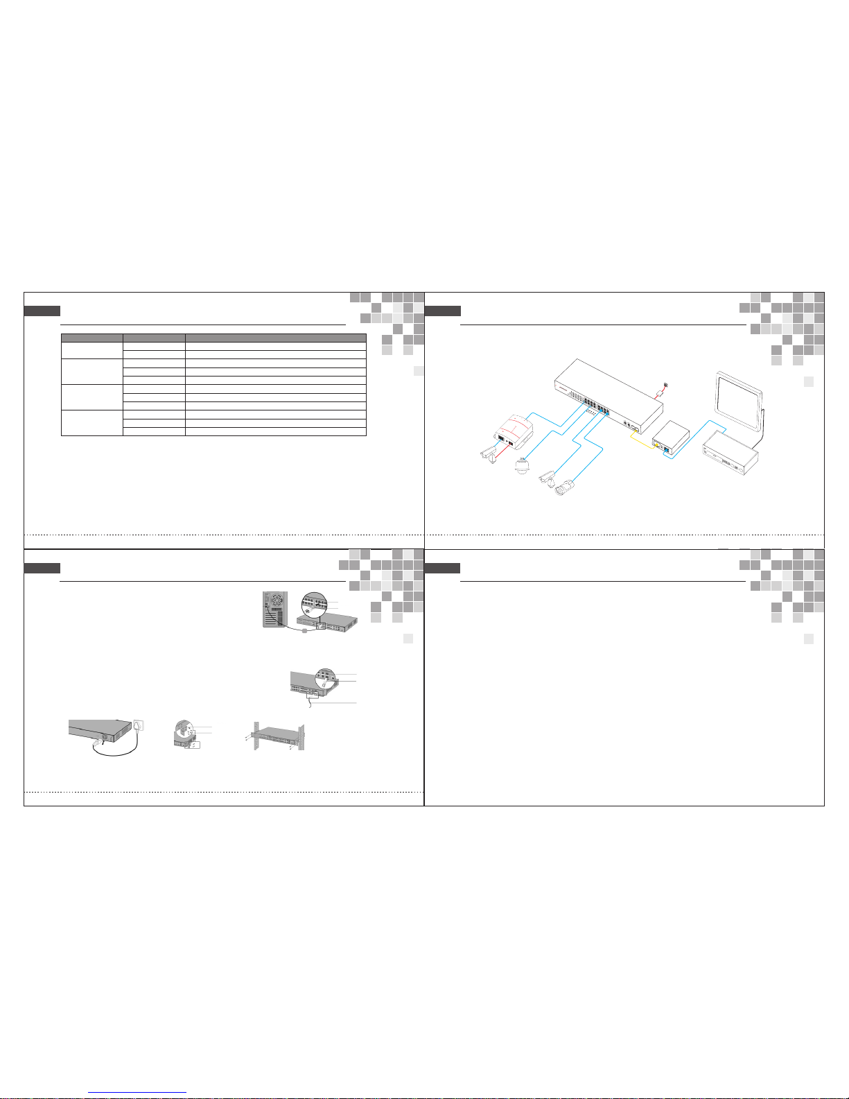
Connection Diagram
Indicator description:
Ind icato r
Sta tus
Des cript ion
OFF
OFF
PoE Indicators: The front panel has light indicators showing the status of PoE activity.
Network Traffic Indicators: The front panel has light indicators showing status of network activity.
SFP Gigabit fiber port: Two combo fiber port, all port support wire-speed forwarding, Rich port configuration. Seaml-ess
connection various network is allowed.
Pow er Indi cator: P WR
Yel low LED ON
Pow er ON, Nor mal Pow er Sup ply
Pow er OFF or Po wer fai lure
Syst em Indi cator
( SYST EM)
Yel low LED O N
norm al Syst em Work ing Sta tus
Yel low LED B link
In Re ading P rogra m, Rest ore Fact ory Set tings
Non -Netw ork Man ageme nt
Lin k indic ator:
(Li nk/ACT )
Gree n LED ONC o n
Gree n LED Bl ink
OFF
PoE i ndica tor: POE
Gree n LED ON
Gree n LED Bl ink
OFF
Correctly Connected Port
Rec eivin g or Send ing dat a
Con necti on fail ed or Abn ormal Li nk
Con nected s tanda rd PD, No rmal Po wer Sup ply
Sho rt Circu it or Ove r Load
No Co nnecti on or Co nnecte d PD is Non -Stan dard PD
Deta il ed d esc ri pt ions fo r th e pr odu ct m od el numb er s
16- port Se ries PO E switc h
IPCP -16P2 G-AF: 1 6-por t 10/10 0Mbps + 2-por t 10/10 0/100 0Mbps u p-lin k ( Combo E thern et port & S FP slot s ) switc h , No. 1-1 6
port s suppo rt POE , IE EE802 .3af, P OE port o utput : 1 5.4wa tts , tot al powe r : 270wa tts
IPCP -16P2 G-AT: 16-p ort 10/ 100Mb ps +2-p ort 10/ 100/1 000Mb ps up-l ink ( Com bo Ethe rnet po rt & SFP sl ots ) swi tch , No.
1-16 p orts su pport P OE , IEEE 802.3 at, POE p ort out put : 25. 5watt s , total p ower : 44 0watt s
Installation guide
Con nect to R J45 por t
1.Co nnect o ne end of R J45 wir e to swit ch, the o ther en d to othe r equip ment, a s
show n as the fi gure on t he righ t;
2.Aft er powe r on, ple ase che ck the LE D indic tor sta tus. If i t is on, it s hows th e
link i s OK, oth erwis e, the li nk is dow n. Then p lease c heck th e link an d make
sure t he othe r equip ment is t urned o n, refe r to the in struc tion on a bove pa ge
for de tails .
Rj45 po rt
Plug
Conn ect to SF P port
PoE sw itch ha s 2 indep enden t SFP por ts. Ple ase ref er to the f ollow ing ste ps for op tical m odule i nstal latio n.
1.Gra sp SFP mo dule an d inser t it in swi tch SFP s lot smo othly t ill the y keep cl ose con tact;
2.Ins ert one e nd of the f iber to t he Rx and T x accor dingl y, and th e other e nd to oth er equi pment , shown a s in the ri ght fig ure;
3.Aft er powe r on, ple ase che ck the LE D indic ator st atus. I f it is on, i t shows t he link i s OK,
othe rwise , the lin k is down . Then pl ease ch eck the l ink and m ake sur e the oth er
equi pment i s turne d on.
SFP Por t
Fiber m odule
Optic al Fibe r
Conn ect to po wer
PoE sw itch ad opts AC 1 00-24 0V, 50/ 60Hz.
1.Ple ase che ck the po wer sup ply spe cific ation m atche s with th e requi red;
2.Con nect sw itch po wer wir e to AC pow er sock et, sho wn as in th e follo wing fi gure.
Power S upply C onnec tion Fi gure Mount ing Kit s Insta llati on Figu re
Rack In stall ation F igure
L Angle I ron
Screw
Afte r insta llati on, ple ase che ck:
If the re is eno ugh spa ce for he at sink ; if the po wer soc ket is su itabl e for swi tch spe cific ation ; if the po wer, sw itch an d rack ar e
prop erly gr ounde d and if th e conne ction b etwee n switc h and oth er netw ork equ ipmen ts are no rmal.
Cat.5
AC Adapt er
PoE Ca
meraIP
PoE Switc h
IP Ca
mera
PoE Splitter
DC O
UT
Cat.
5
Monit or
Cat.
5
NVR
Video l in
e
Fiber
media
con
verte r
PD-Powered Device
Power over Ethernet Splitter
OFF:12V
ON:5V
PoE RUN
PoE IN
DC OUT
DC RUN
Ethernet out
IN
OUT
PoE IP
Camer a
Po
E IP Came r
a
 Loading...