

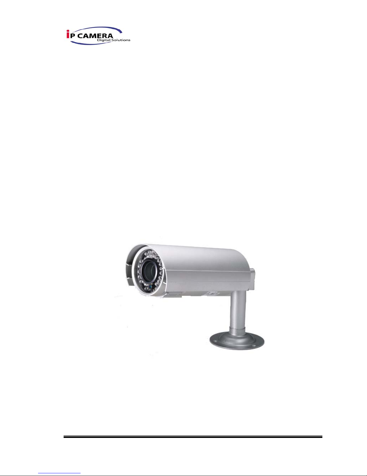
IP Camera H.264 MegaPixel, IR IP CAMERA User Manual
1/40
User Manual
H.264 MegaPixel
IR IP CAMERA
2/40
WARINGS
TO REDUCE THE RISK OF FIRE OR ELECTRIC SHOCK, DO NOT EXPOSE THIS
PRODUCT TO RAIN OR MISTURE.
DO NOT INSERT ANY METALLIC OBJECT THROUGH VENTILATION GRILLS.
CAUTION
CAUTION
RISK OF ELECTRIC SHOCK
DO NOT OPEN
CAUTION:TO REDUCE THE RISK OF ELECTRIC SHOCK.
DO NOT REMOVE COVER (OR BACK).
NO USER-SERVICEABLE PARTS INSIDE.
REFER SERVICING TO QUALIFIED SERVICE PERSONNEL.
COPYRIGHT
THE TRADEMARKS MENTIONED IN THE MANUAL ARE LEGALLY REGISTERED
TO THEIR RESPECTIVE COMPANIES.

3/40
Content
I. PREFACE....................................................................................................................................... 4
II. PRODUCT SPECIFICA TIONS....................................................................................................... 4
III. PRODUCT INSTALLATION........................................................................................................... 6
A. MONITOR SETTING.....................................................................................................................................6
B. HARDWARE INST ALLATION AND I/O PIN ASSIGNMENT............................................................................... 8
C. IP ASSIGNMENT .......................................................................................................................................12
D. INSTALL ACTIVEX CONTROL:...................................................................................................................14
IV. LIVE VIDEO.................................................................................................................................. 16
V. CONFIGURATION........................................................................................................................ 18
A. SYSTEM ...................................................................................................................................................19
B. NETWORK................................................................................................................................................ 22
C. A/V SETTING ...........................................................................................................................................26
D. EVENT LIST..............................................................................................................................................33
VI. NETWORK CONFIGURATION.................................................................................................... 39
VII. P ACKAGE CONTENTS............................................................................................................... 40
VIII. FACTORY DEFAULT ................................................................................................................... 40

4/40
I. Preface
This is a 2M-Pixel CMOS IP camera with the web server built in. User can view
real-time video via IE browser. It supports H.264, JPEG and MPEG4(3GPP Only)
video compression which provides smooth and high video quality. The video can
be stored in the SD card and playback remotely.
With user friendly interface, it is an easy-to-use IP camera which is designed for
security application.
II. Product Specifications
z Support video out
z High Definition 30FPS support(720P)
z IP66
z 2M-Pixel CMOS Sensor
z Power over Ethernet available
z IR LED Built in 20M available
z Mechanism IR Cut Filter Available
z H.264/ MJPEG/ MPEG4 (3GPP Only) Compression Format
z SD Card backup
z 2-way audio
z Support Cell phone/PDA/3GPP
z SDK for Software Integration
z Free Bundle 36 Channel Recording Software
Specifications
Hardware
CPU ARM 9 ,32 bit RISC
RAM 256MB
Flash 16MB
Image Sensor 1/3” CMOS(2M-Pixel)
Support DC IRIS Yes
Lens Type Vari-focal 3.6~16mm Lens
ICR Mechanism IR cut Filter

5/40
Built-in 35 IR LED LED
IR Distance-20M
I/O 1 in/ 1 Relay Out
Video Out x1
Audio In x1
Audio Out x1
Power over Ethernet Yes (Optional)
Power Consumption DC 12V
Dimensions
∮83mm * H180mm
Network
Ethernet 10/ 100 Base-T
Network Protocol HTTP, TCP/ IP, UDP, SMTP, FTP, PPPoE,
DHCP, DDNS, NTP, UPnP, 3GPP
System
Video Resolution
1600x1200, 1280x1024, 1280x960,1280x720,
800x600,640x480, 320x240, 176x144
Video Adjust Brightness, Contrast, Sharpness, BLC, Night
Mode
Triple Streaming Yes
Image Snapshot Yes
Full Screen
Monitoring
Yes
Privacy Mask Yes, 3 different areas
Compression Format H.264/ JPEG/ MPEG4 (3GPP only)
Video Bitrates Adjust CBR, VBR
Motion Detection Yes, 3 different areas
Triggered Action Mail, FTP, Save to SD card, Relay
Pre/ Post Alarm Yes, configurable
Security Password protection
Firmware Upgrade HTTP mode, can be upgraded remotely
Simultaneous
Connection
Up to 10
Audio Yes, 2-way
SD card management
Recording Trigger Motion Detection, IP check, Network break down
(wire only),Schedule, Relay
6/40
Video Format AVI, JPEG
Video Playback Yes
Delete Files Yes
Web browsing requirement
OS Windows 2000, XP, 2003, Microsoft IE 6.0 or
above
Hardware
Suggested
Intel Dual Core 1.66G,RAM: 1024MB, Graphic
card: 128MB
Minimum Intel-C 2.8G, RAM: 512MB, Graphic card: 64MB
III. Product Installation
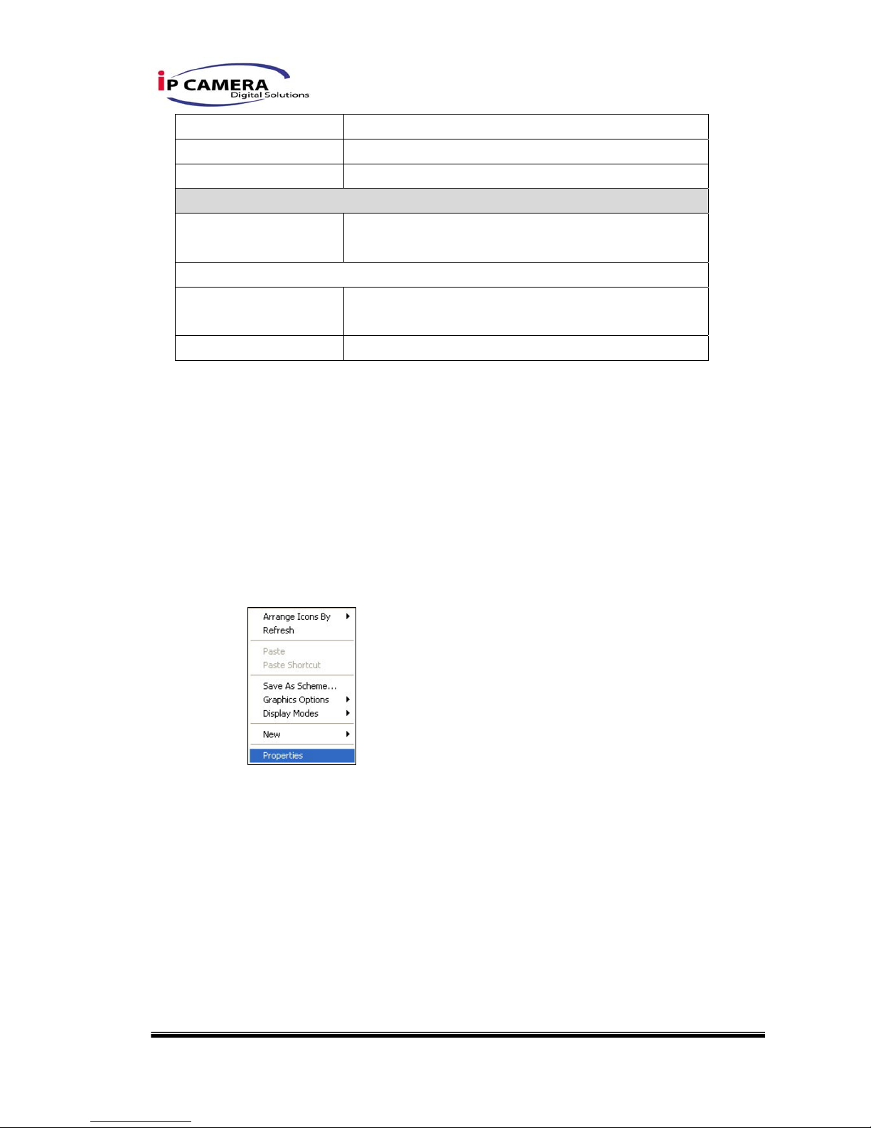
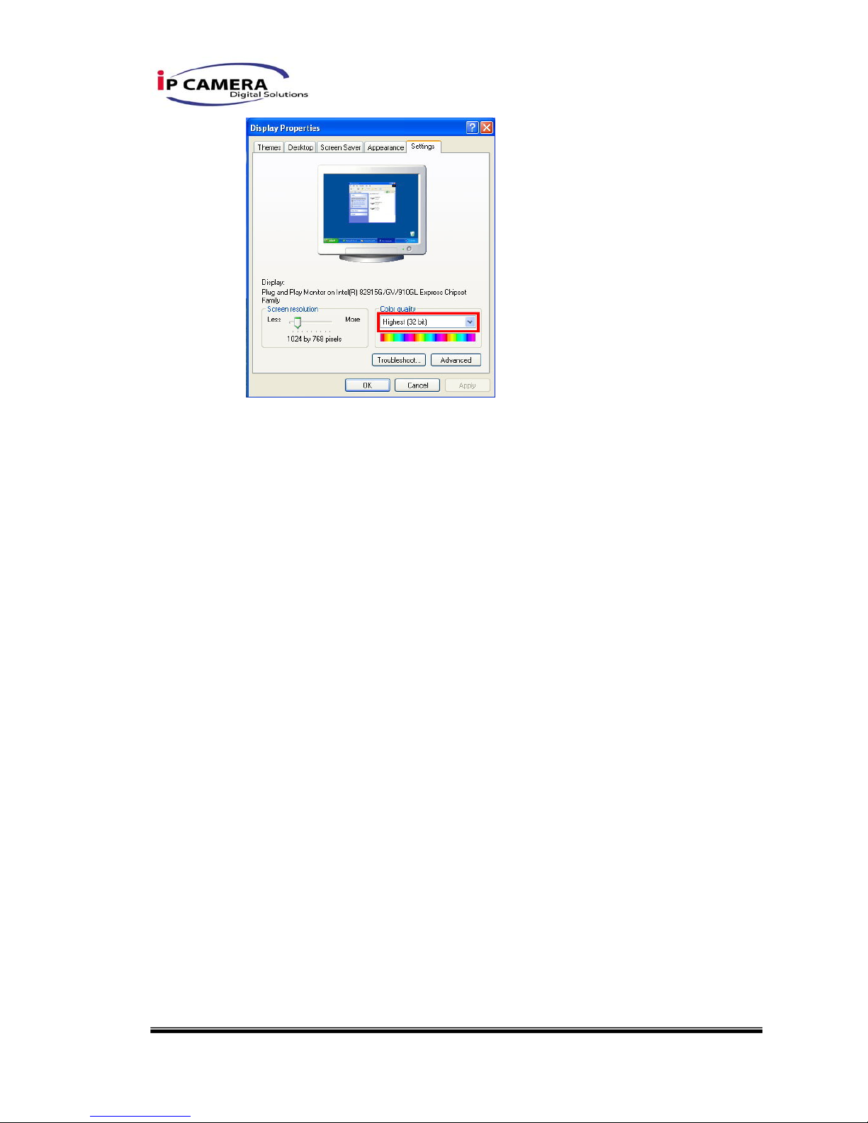
A. Monitor Setting
i. Right-Click on the desktop. Select “ Properties”
ii. Change color quality to highest (32bit).
7/40
8/40
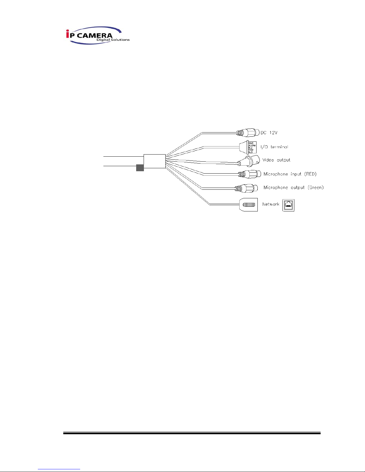
B. Hardware Installation and I/O Pin
Assignment
i. Connect a power adapter and IP Camera to PC or local network
ii. I/O Control Instruction
I/O terminal connector – used in application, for e.g., motion detection, event
triggering, alarm notifications. It provides the interface to:
1 Digital Input (GND+Alarm) – An alarm input for connecting devices that can
toggle between an open and closed circuit, for example: PIRs, door/window
contacts, glass break detectors, etc. When a signal is received the state changes
and the input becomes active.
Relay output (COM +N.O.) / (COM+N.C.) – An output to Relay switch, for
example: LEDs, Sirens, etc
Digital Input
Alarm Input
1. GND (Ground) : Initial state is LOW
2. Alarm : Max. 50mA, DC 3.3V
Relay Output
1. N.C. (Normally Close): Max. 1A, 24VDC or 0.5A, 125VAC
2. COM: (Common)
3. N.O. (Normally Open): Max. 1A, 24VDC or 0.5A, 125VAC
9/40
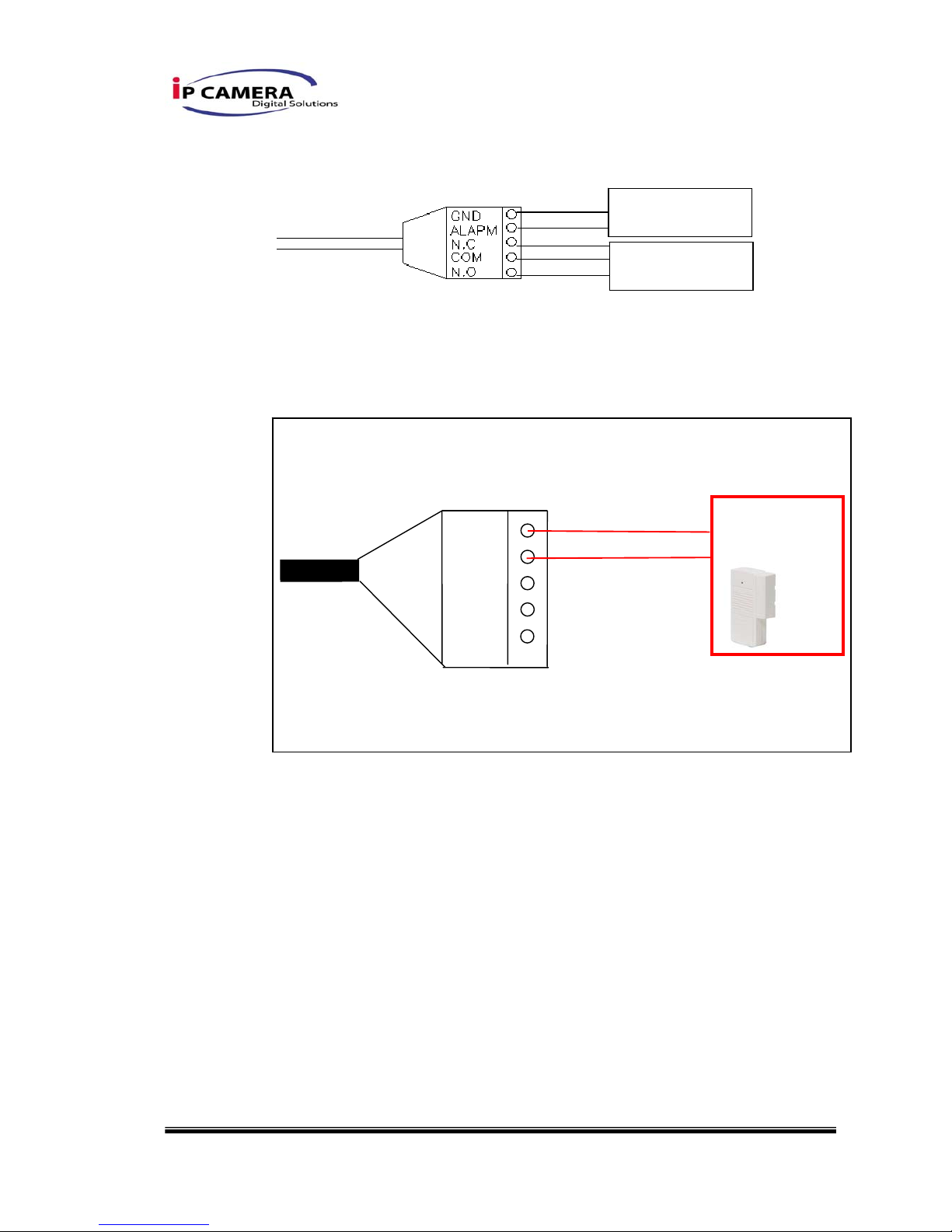
Relay
1. Digital Input connection
GND
ALARM
N.C.
COM
N.O.
Door/Window
Contacts
ALARM IN
RELAY OUT
10/40
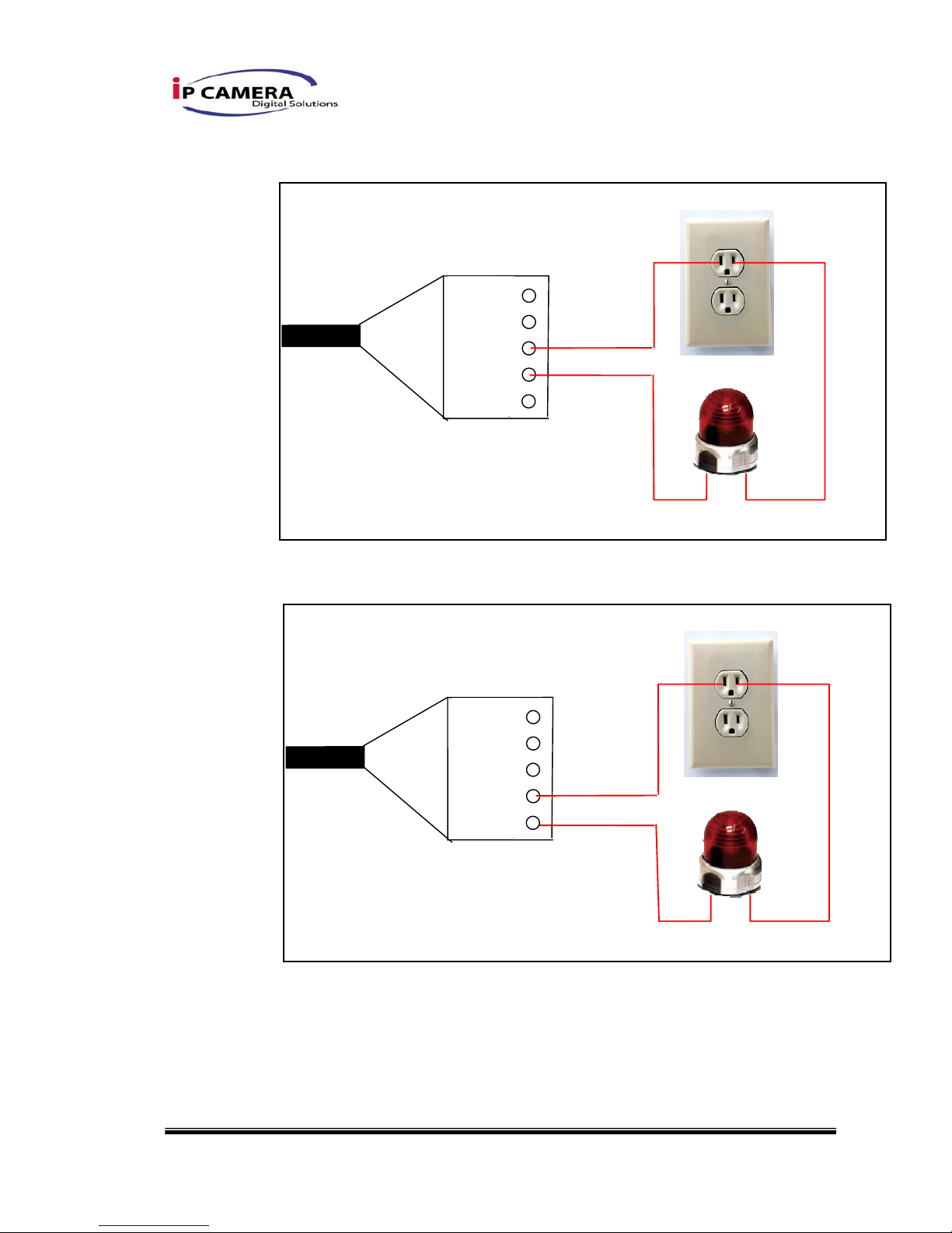
2. Relay Output Connection
Or
iii. PoE ( Power Over Ethernet)(Optional) 802.3af, 15.4W PoE Switch is
recommended
Power over Ethernet (PoE) is a technology that integrates power into a
standard LAN infrastructure. It enables power to be provided to the
network device, such as an IP phone or a network camera, using the
same cable as that used for network connection. It eliminates the need
GND
ALARM
N.C.
COM
N.O.
GND
ALARM
N.C.
COM
N.O.

11/40
for power outlets at the camera locations and enables easier application
of uninterruptible power supplies (UPS) to ensure 24 hours a day , 7 days
a week operation.
Ethernet
PoE Switch
PoE IP Camera
PoE IP Camera
Ethernet Cable
Ethernet Cable
12/40
C. IP Assignment
i. Use the software, “IP Installer” to assign the IP address of IP CAMERA.
The software is in the attached software CD.
ii. IP installer supports two languages
a. IPInstallerCht.exe:Chinese version
b. IPInstallerEng.exe:English version
iii. There are 3 kinds of IP configuration.
a. Fixed IP (Public IP or Virtual IP)
b. DHCP (Dynamic IP)
c. Dial-up (PPPoE)
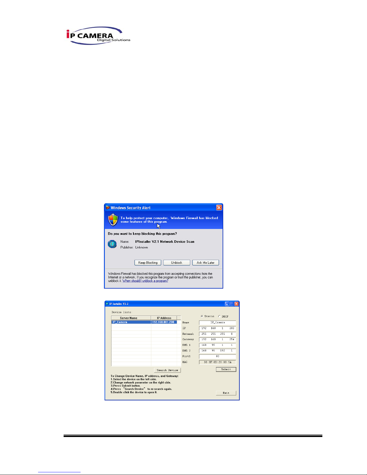
iv. Execute IP Installer
v. For Windows XP SP2 user, it may popup the following message box.
Please click “Unblock”.
vi. IP Installer configuration:
vii. IP Installer will search all IP Cameras connected on Lan. The user can
click “Search Device” to search again.
viii. Click one of the IP Camera listed on the left side. The network
 Loading...