

Page 1
User Manual
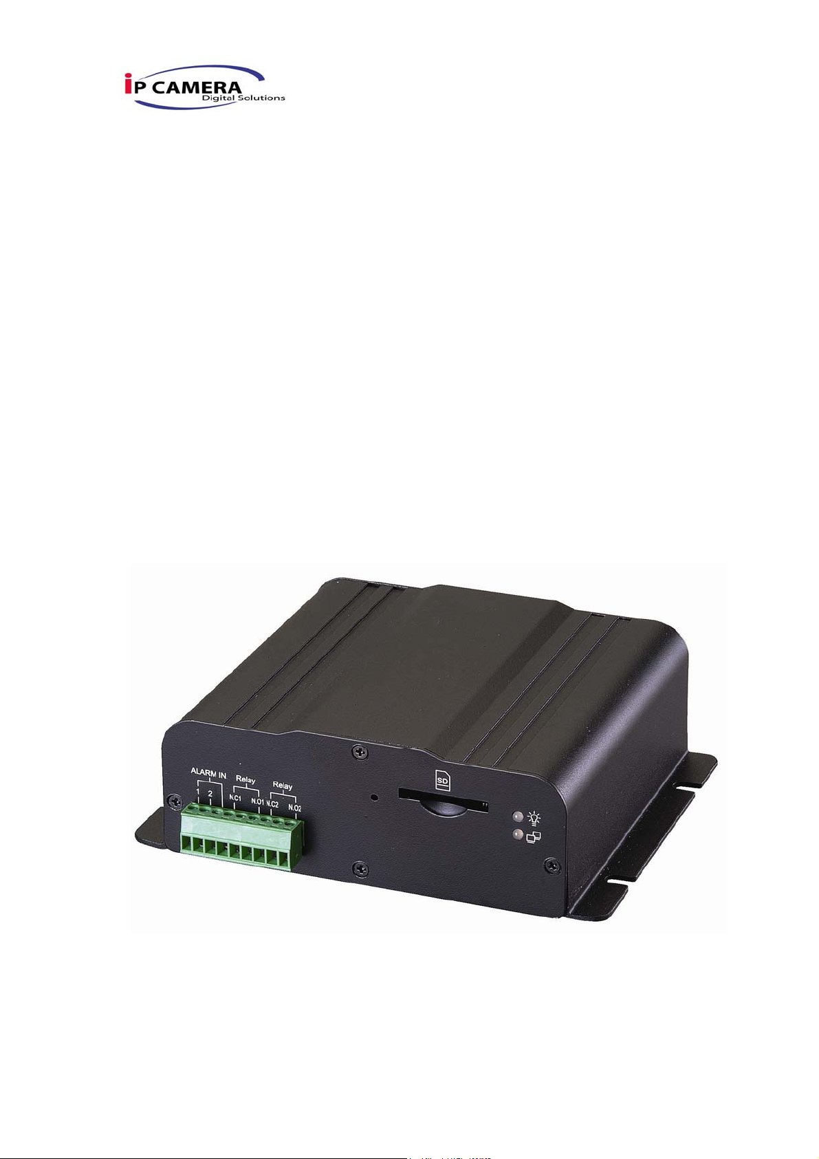
IPw-TX264
1Ch Video Server
1/42
Page 2

I. Preface
Video Server is a 1 channel video server with the web server built in. User views
real-time video via IE browser. Video Server supports H.264/ MPEG-4 (3GPP
Only)/ JPEG video compression which provides smooth and high video quality.
The video can be stored in the SD card, and playback remotely.
With user friendly interface, it is an easy-to-use video server which can connect
any kind of analogue camera to fit the customer’s need.
II. Product Specifications
z 1-CH Input
z H.264/ MJPEG/MPEG4 (3GPP only) compression
z SD card backup
z 2-way audio
z Support Cell Phone/PDA/3GPP
z 3 Streaming
z Power Over Ethernet available
z SDK for Software Integration
z Wireless (Optional)
z Free Bundle 36 ch recording software
Specifications
Hardware
CPU ARM 9 ,32 bit RISC
DDR2 128MB
Flash 8MB
Video in 1 in BNC connector
Video Looping Input 1
Audio in/ out 1 in/ 1 out
I/O 2 in/ 2 Relay out (COM. & N.O. & N.C.)
Relay Out: DC 24V@1A AC [email protected]
RS-485 1, for PTZ control
RS-232 YES
4/42
Page 3
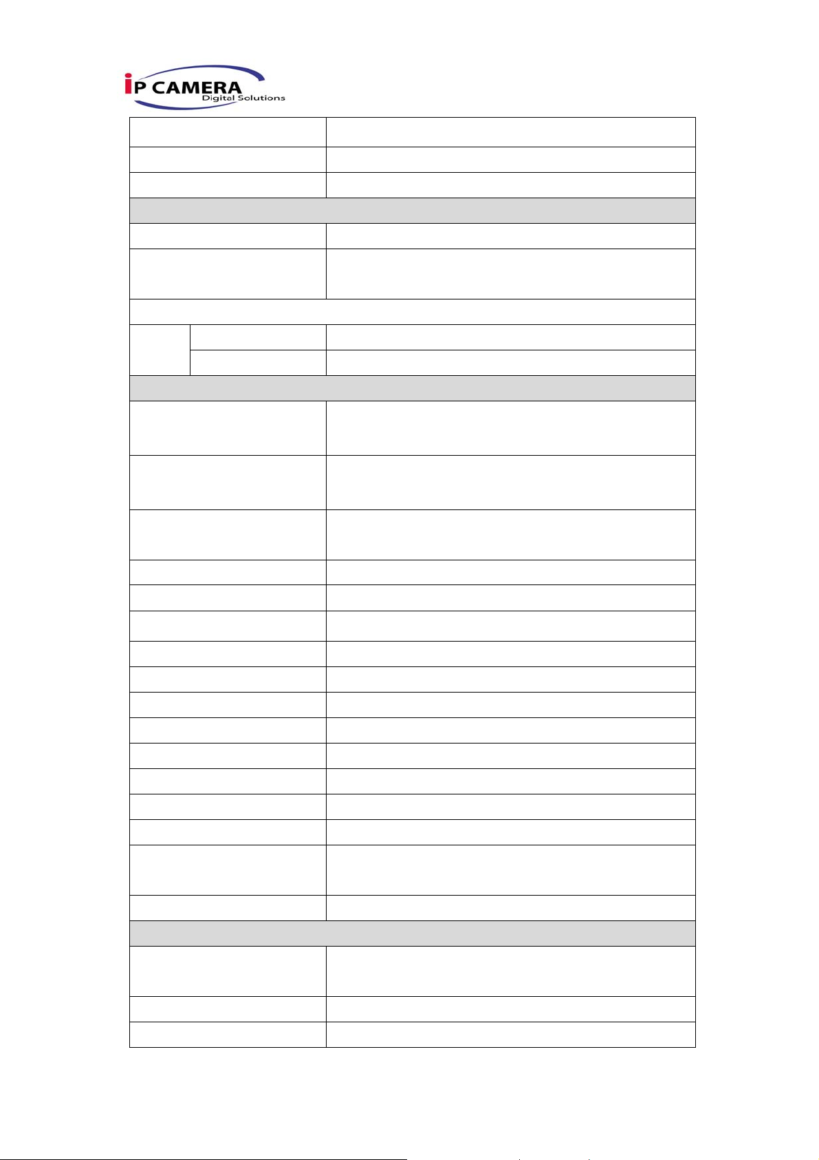
Power Over Ethernet YES (optional)
Power Consumption DC 12V, 350mA, 4W
Dimensions 134mm (W) x 42mm (L) x 107mm (D)
Network
Ethernet 10/ 100 Base-T
Network Protocol HTTP, TCP/ IP, SMTP, FTP, PPPoE, DHCP,
DDNS, NTP, UPnP, 3GPP
Wireless (Optional)
Wireless 802.11b/g
Security WEP,WPA-PSK,WPA2-PSK
System
NTSC - 720x480, 704x480,352x240, 176x120
Video Resolution
PAL – 720x576, 704x576, 352x288, 176x144
Image Frame rate 30/25 fps (NTSC/PAL)
Video adjust Brightness, Contrast, Saturation, Hue,
Sharpness
Triple Streaming Yes
Image snapshot Yes
Full screen monitoring Yes
Privacy Mask Yes, 3 different areas
Compression format H.264/ JPEG/ MPEG4 (3GPP only)
Video bitrates adjust CBR, VBR
Motion Detection Yes, 3 different areas
Triggered action Mail, FTP, Save to SD card, Relay
Pre/ Post alarm Yes, configurable
Security Password protection
Firmware upgrade HTTP mode, can be upgraded remotely
Simultaneous
Up to 10
connection
Audio Yes, 2-way
SD card management
Recording trigger Motion Detection, IP check, Network break down
(wire only),schedule, Alarm
Video format AVI, JPEG
Video playback Yes
5/42
Page 4

Delete files Yes
Web browsing requirement
OS Windows 2000, XP, 2003, Microsoft IE 6.0 or
above
Hardware Suggested Intel Dual Core 1.66G,RAM: 1024MB, Graphic
card: 128MB
Minimum Intel-C 2.8G, RAM: 512MB, Graphic card: 64MB
6/42
Page 5
III. Product Installation
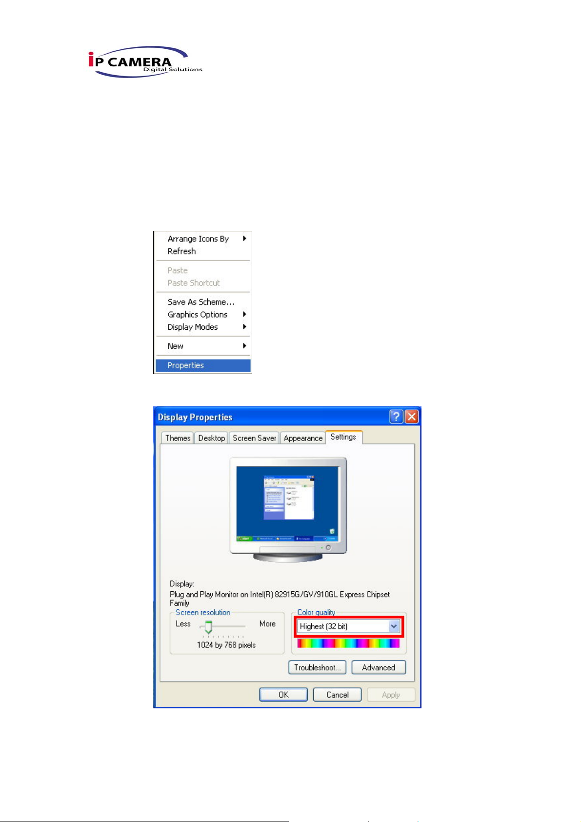
A. Monitor Setting
i. Right-Click on the desktop. Select “ Properties”
ii. Change color quality to highest (32bit).
7/42
Page 6

B. Hardware Installation
B-1: Hardware Connection
i. Connect power adaptor
ii. Connect Video Server to PC or network with Ethernet cable
iii. Set up the network configurations according to the network environment.
For further explanation, please refer to chapter VI, “Network
Configuration for Video Server”.
B-2: I/O Control Instruction
I/O terminal connector – used in application, for e.g., motion detection, event
triggering, alarm notifications. It provides the interface to:
Digital Input (GND+Alarm) – An alarm input for connecting devices that can toggle
between an open and closed circuit, for example: PIRs, door/window contacts, glass
break detectors, etc. When a signal is received the state changes and the input becomes
active.
Relay output (COM +N.O.) – An output to Relay switch, for example: LEDs, Sirens,
etc
8/42
Page 7
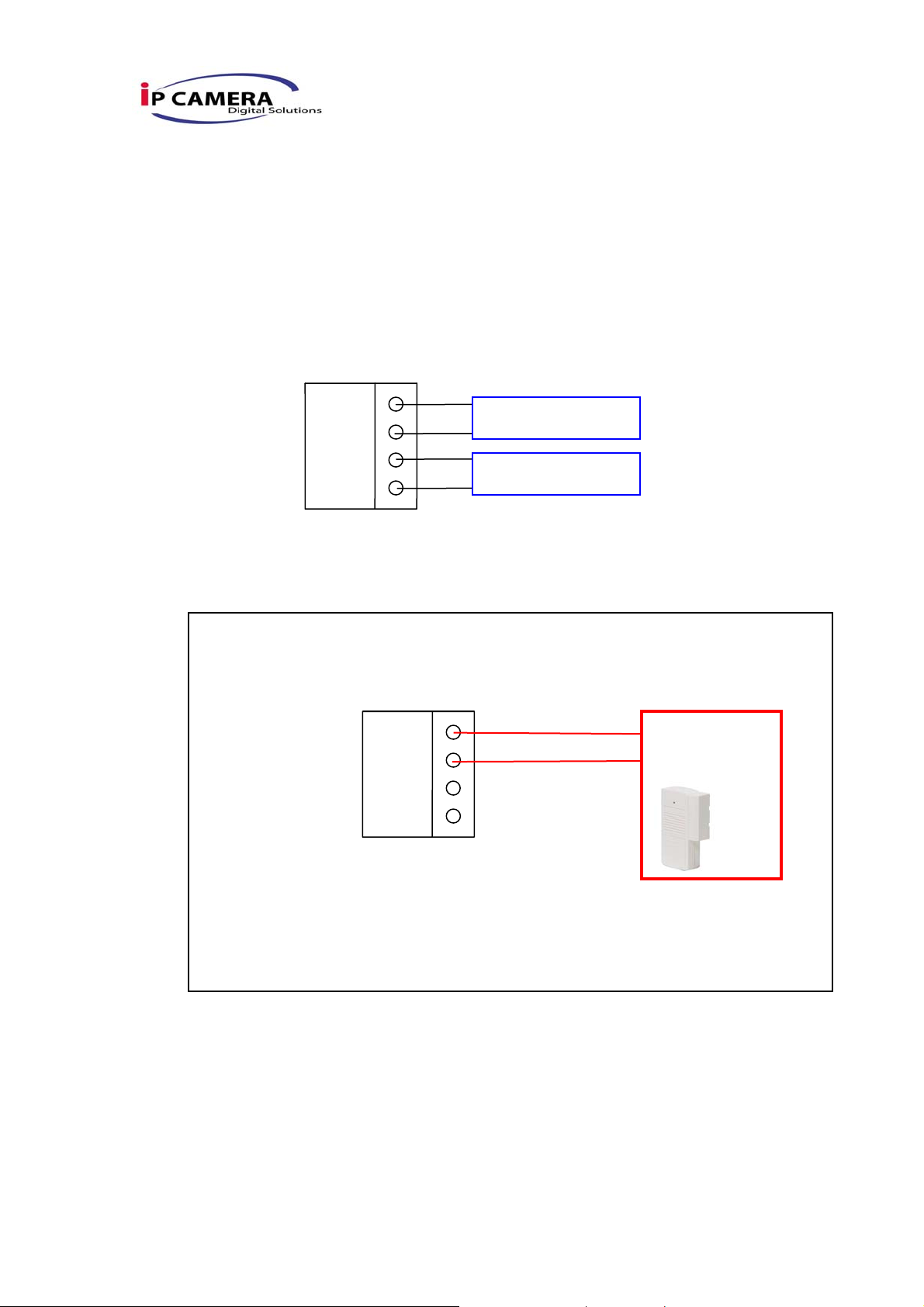
Digital Input
Alarm Input
1. GND (Ground) : Initial state is LOW
2. Alarm : Max. 50mA, 12VDC
Relay Output
1. COM: (Common)
2. N.O. (Normally Open): Max. 1A, 24VDC or 0.5A, 125VAC
ALARM
B-2 Relay Connection:
Digital Input connection
GND
COM
N.O.
ALARM IN
Relay Out
GND
ALARM
COM
N.O.
Door/Window
Contacts
9/42
Page 8
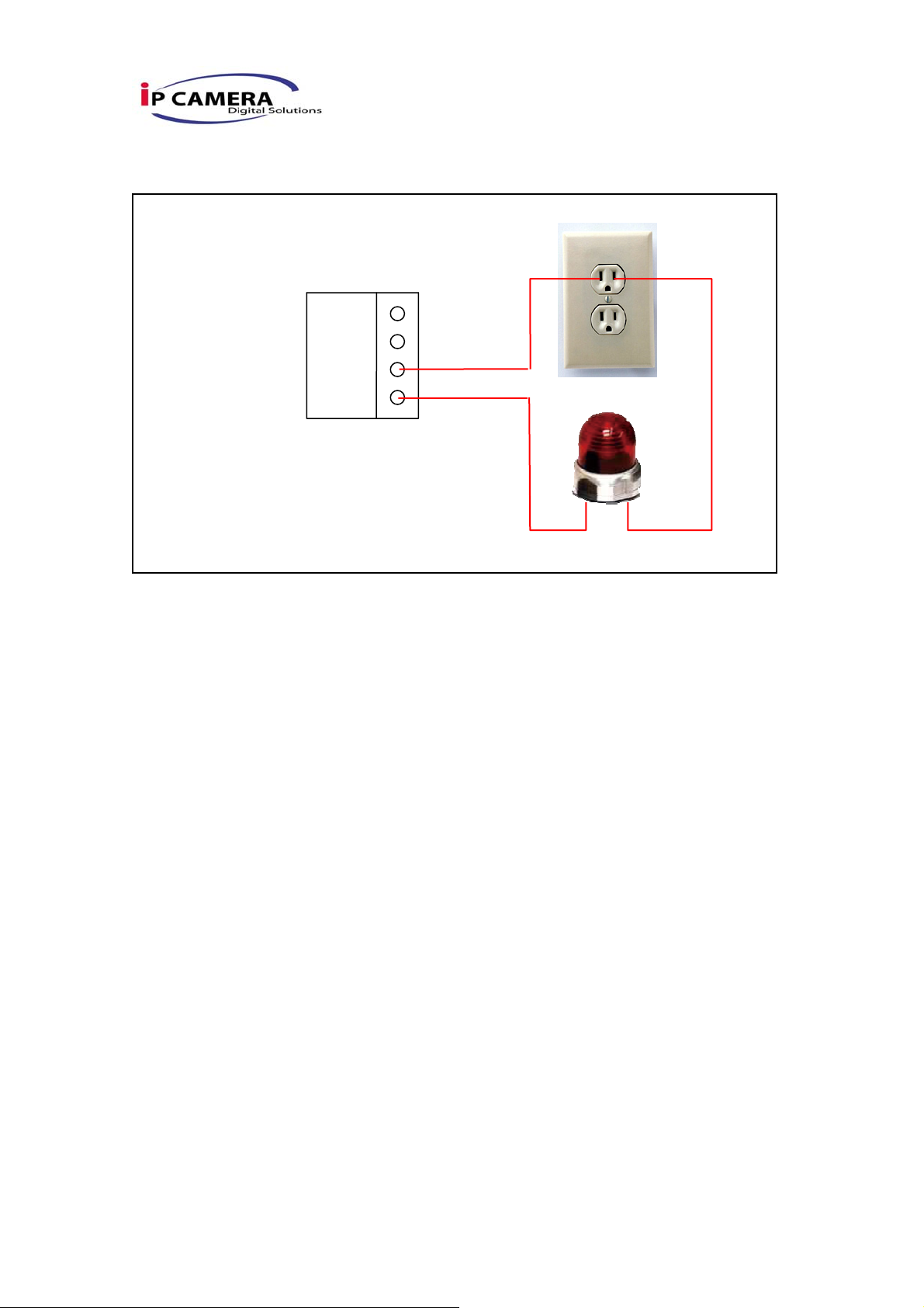
Relay Output Connection
GND
ALARM
COM
N.O.
C. IP Assignment
i. Use the software, “IP Installer” to assign the IP address of Video Server.
The software is in the attached software CD.
ii. There are two languages for the IP installer
a. IPInstallerCht.exe:Chinese version
b. IPInstallerEng.exe:English version
iii. There are 3 kinds of IP configuration.
a. Fixed IP (Public IP or Virtual IP)
b. DHCP (Dynamic IP)
c. Dial-up (PPPoE)
iv. Execute IP Installer
v. For Windows XP SP2 user, it may popup the following message box.
Please click “Unblock”.
10/42
Page 9
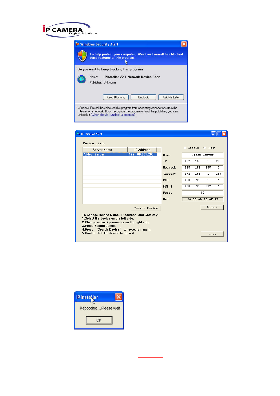
vi. IP Installer configuration:
vii. IP Installer will search all IP Devices connected on Lan. The user can
click “Search Device” to search again.
viii. Click the Video Server listed on the left side. The network configuration
of this Video Server will show on the right side. You may change the
“name” of the Video Server to your preference (eg: Office, warehouse).
Change the parameter and click “Submit” then click “OK”. It will apply
the change and reboot the Device.
ix. Please make sure the subnet of PC IP address and Video Server IP
address are the same.
The same Subnet:
Video Server IP address: 192.168.1
11/42
.210
Page 10
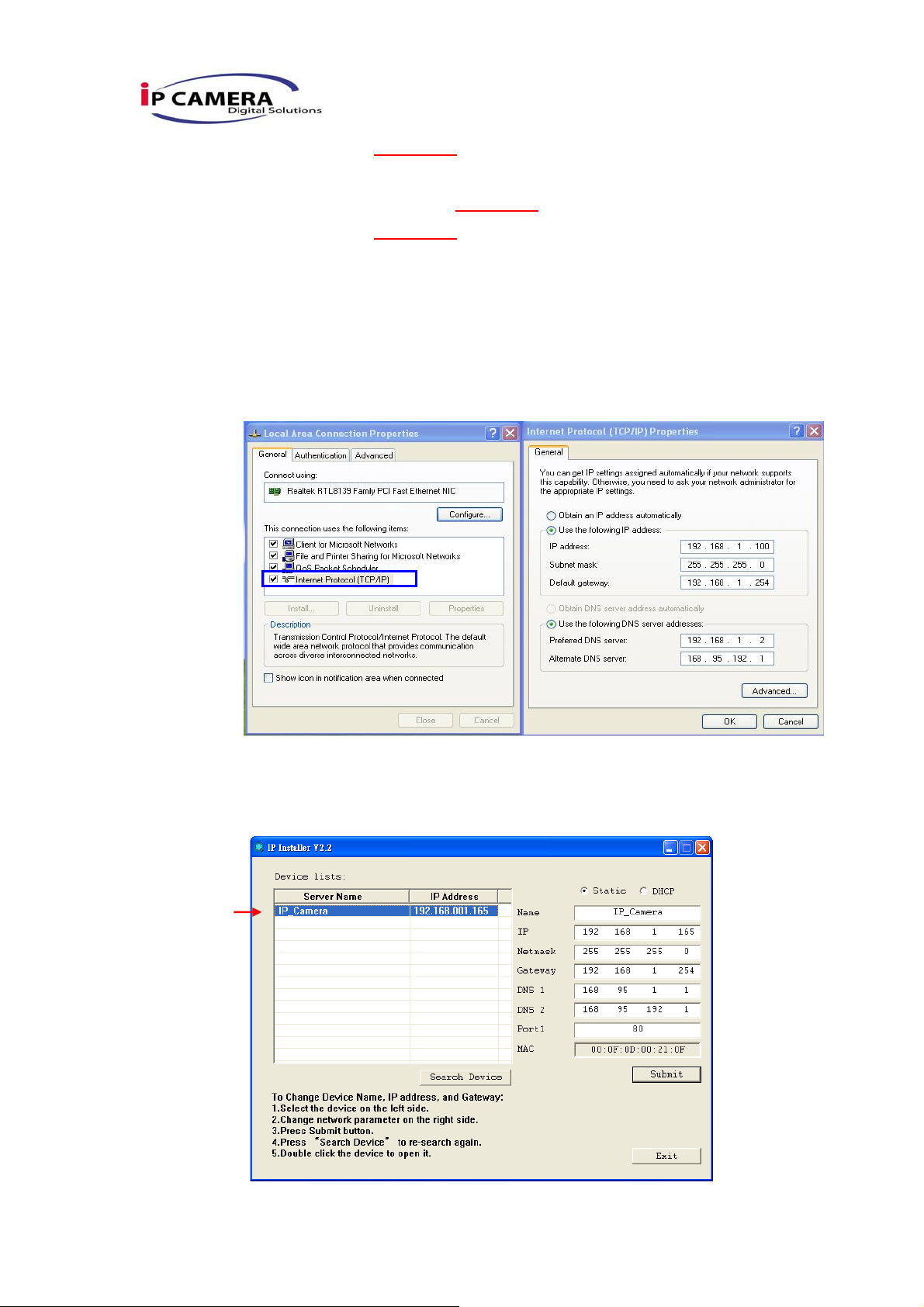
PC IP address: 192.168.1.110
Different Subnets:
Video Server IP address: 192.168.2.210
PC IP address: 192.168.1.110
To Change PC IP address:
Control PanelÆNetwork ConnectionsÆLocal Area Connection
PropertiesÆInternet Protocol (TCP/IP) ÆProperties
Please make sure your Video Server and PC have the same Subnet. If
not, please change Video Server subnet or PC IP subnet accordingly.
x. A quick way to access remote monitoring is to left-click the mouse twice
on a selected Video Server listed on “Device list” of IP Installer. An IE
browser will be opened.
12/42
Page 11
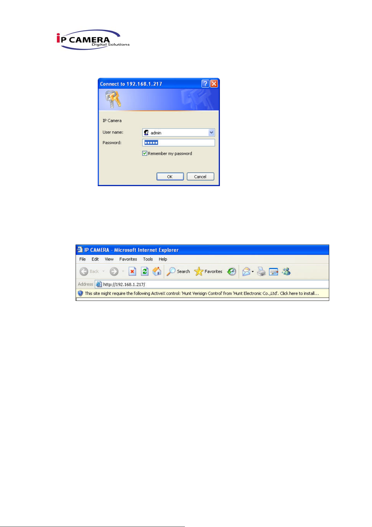
xi. Then, please key in the default “user name: admin” and “password:
admin”.
D. Install ActiveX control:
For the first time to view the video via IE, it will ask you to install the ActiveX
component.
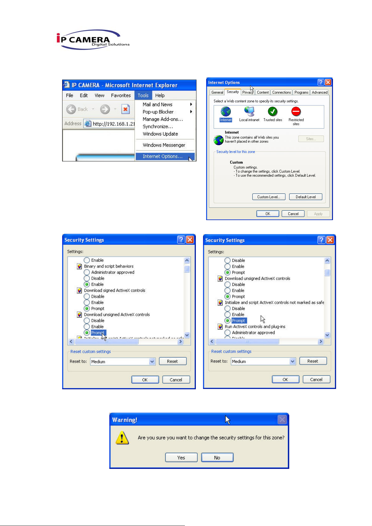
If the installation failed, please check the security setting for the IE browser.
i. IE Æ Tools Æ Internet Options… Æ Security Tab Æ Custom Level… Æ
Security Settings Æ Download unsigned ActiveX controlsÆ Select
“Enable” or Prompt.
ii. IE Æ Tools Æ Internet Options… Æ Security Tab Æ Custom Level…
ÆInitialize and script ActiveX controls not marked as safe Æ Select
“Enable” or Prompt.
13/42
Page 12
1 2
3 4
5
When popup the following dialogue box, click “Yes”.
14/42
Page 13
IV. Live Video
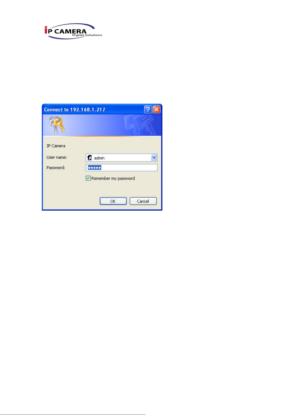
Start a IE browser, type the IP address of the Video Server in the address field. It will
show the following dialogue box. Key-in the user name and password. The default
user name and password are “admin” and “admin”.
When connect to the Video Server。The following program interface shows.
15/42
Page 14
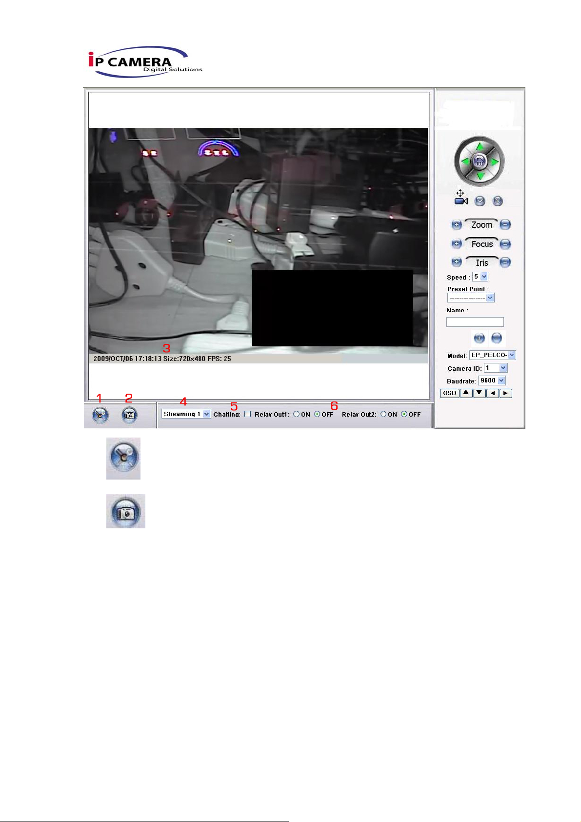
1. :Get into the administration page
2. :Video Snapshot
3. Shows how many people connect to this Video Server
4. Show system time, video resolution, and video refreshing rate
5. Video Server support s 2-way audio. Click the “Chatting” check box. Then you can
use microphone which connect to the PC to talk to server side, which is Video
Server side.
6. Select PTZ protocol to control the PTZ camera which is connected to this video
server. The PTZ function will be slightly different depends on which protocol to
use.
Double-click the video, it will change to full screen mode. Press “Esc” or double-click
the video again, it will change back to normal mode.
Right-Click the mouse on the video, it will show a pop-up menu.
16/42
Page 15
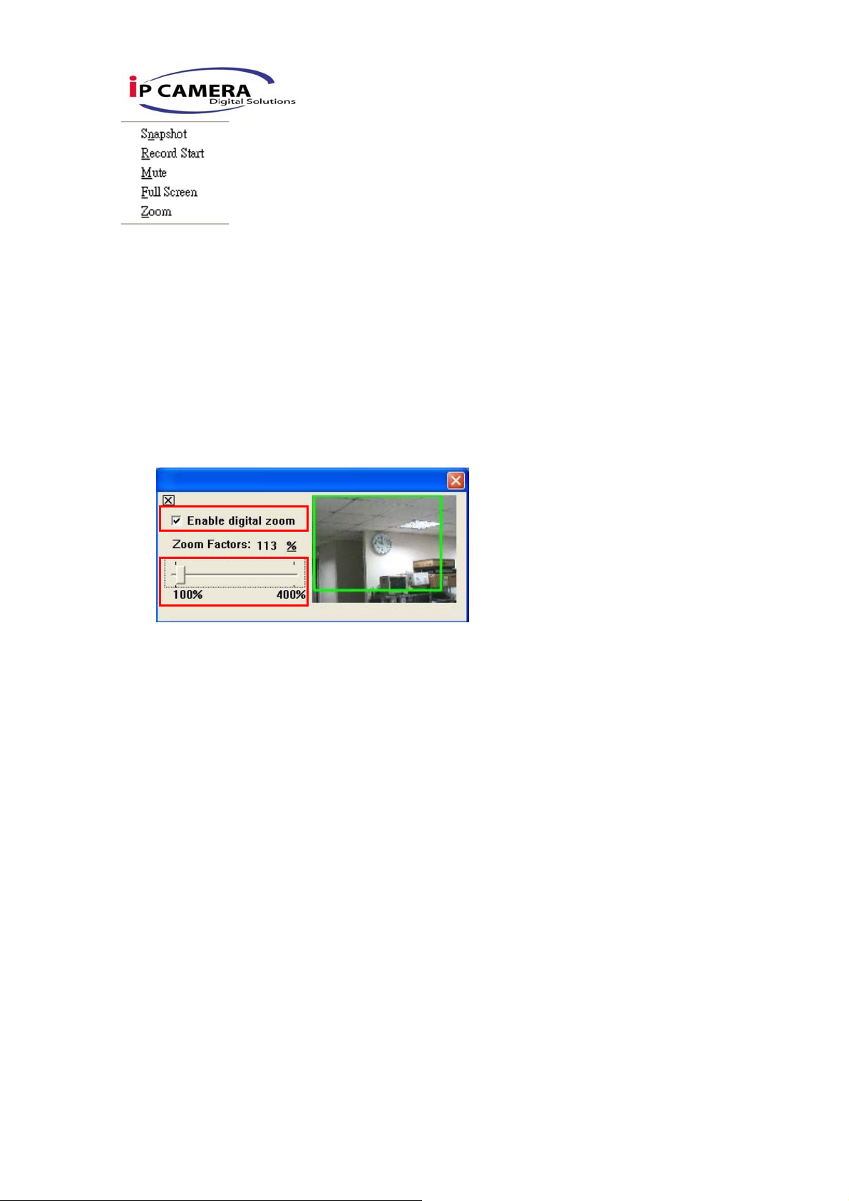
1. Snapshot:Save a JPEG picture
2. Record Start:Record the video in the local PC. It will ask you where to save the
video. To stop recording, right-click the mouse again. Select “Record Stop”. The
video format is AVI. Use Microsoft Media Player to play the recorded file.
3. Mute:Turn of the audio. Click again to turn on it.
4. Full Screen:Full-screen mode.
5. Zoom : Enable zoom-in and zoom-out functions. Select “Enable digital zoom”
option first within the pop-up dialogue box and then drag and drop the bar to
adjust the zoom factors.
17/42
Page 16
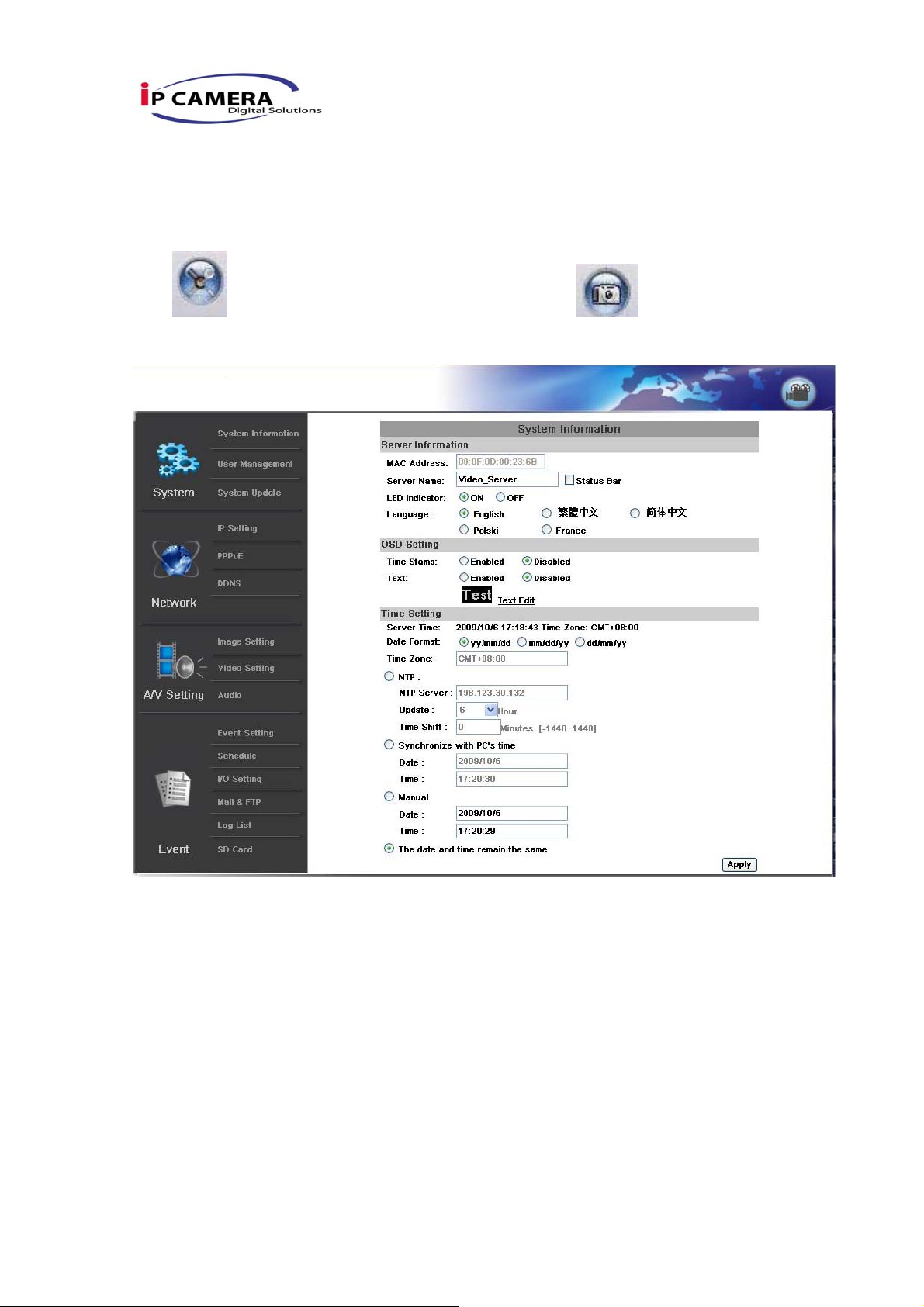
V. Video Server Configuration
Click to get into the administration page. Click to back to the live
video page.
18/42
Page 17
A.System
i、 System Information
a. Server Information:Set up the camera name, select language, and
set up the camera time.
1. Server Name:This is the Video Server name. This name will
show on the IP Installer.
2. Select Language:There are English, Traditional Chinese, and
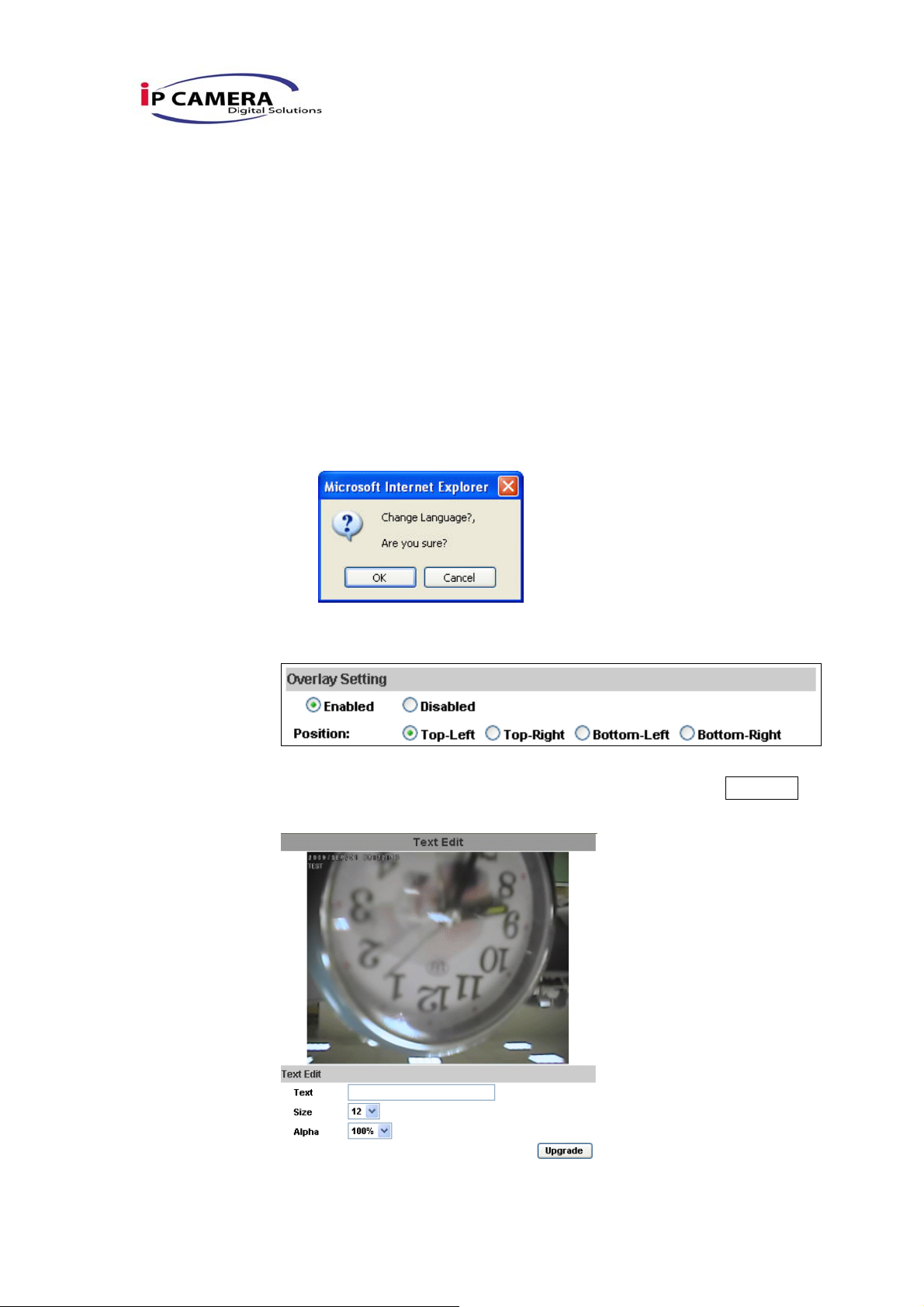
Simple Chinese to select. When change, it will show the
following dialogue box for the confirmation of changing
language.
b. Overlay Setting: select a position where date & time showing on
screen.
Moreover, click Text Edit can entry to adjust the OSD contents
which is including Size and Alpha of text. Finally, click Upgrade
button to reserve the setting.
c. Server time setting:Select options to set up time - “NTP”,
19/42
Page 18
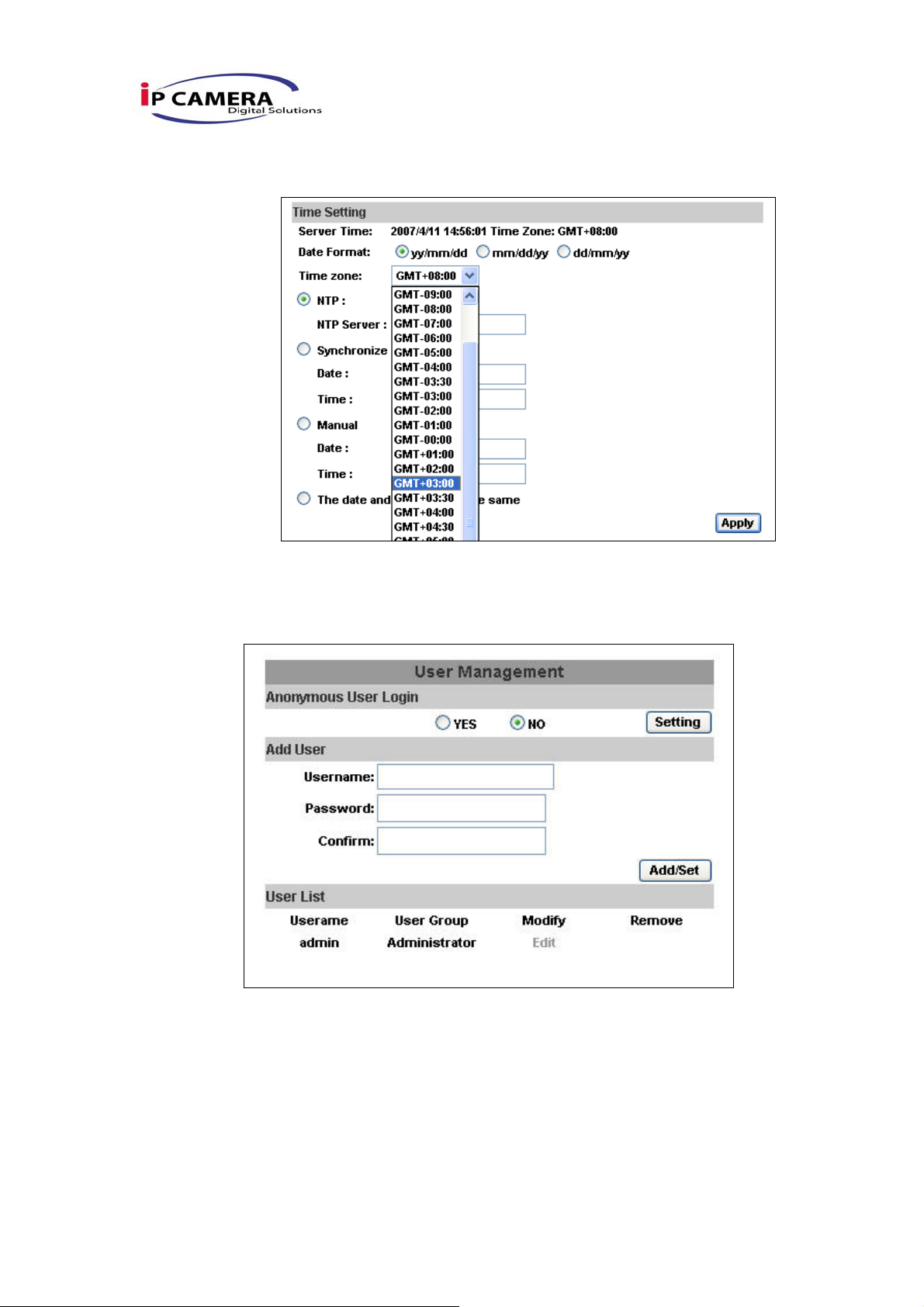
“Synchronize with PC’s time”, “Manual”, “The date and time remain
the same”.
ii、 User Management
Video Server supports three different users, administrator, general user,
and anonymous user.
a. Anonymous User Login:
Yes:Allow anonymous login
No:Need user name & password to access this Video Server
b. Add user:
Type the user name and password, then click “Add/Set”.
Note: Allow guest to login as a Guest. Guest is only allowed to
browse the page.
20/42
Page 19

c. Click “edit” or “delete” to modify the user.
21/42
Page 20
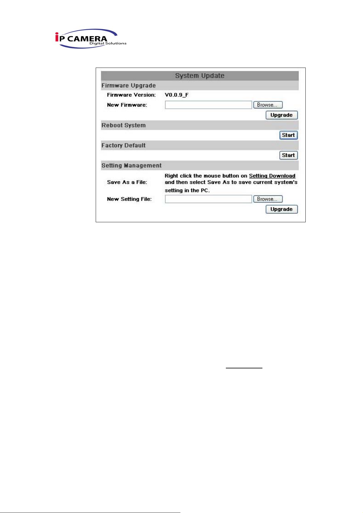
iii、 System update:
a. To update the firmware online, click “Browse…” to select the
firmware. Then click “Upgrade” to proceed.
b. Reboot system:re-start the IP camera
c. Factory default:delete all settings and restore defaults system.
d. Setting Management:User may download the current setting to PC,
or upgrade from previous saved setting.
1. Setting download:
Right-click the mouse button on Setting Download Æ Select
“Save AS…” to save current IP CAM setting in PC Æ Select
saving directory Æ Save
2. Upgrade from previous setting
Browse Æ search previous setting Æ open Æ upgrade Æ
Setting update confirm Æ click index.html. to return to main
page
22/42
Page 21
B.Network
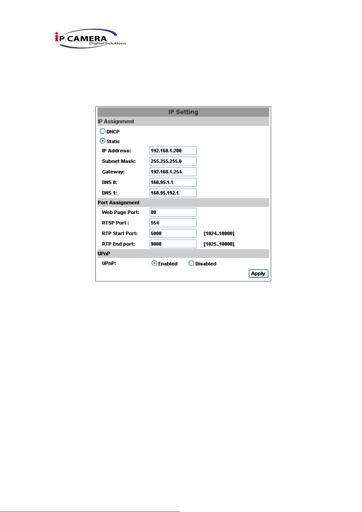
i、 IP Setting
Video Server supports DHCP and static IP.
a. DHCP:Using DHCP, IP Vandal Dome will get all the network
parameters automatically.
b. Static IP:Please type in IP address, subnet mask, gateway, and
DNS manually.
c. Port Assignment: user may need to assign different port to avoid
conflict when setting up IP assignment.
1. Web Page Port: setup web page connecting port and video
transmitting port (Default: 80)
2. RTSP Port: setup port for RTSP transmitting (Default: 554)
3. R TP Start and End Port: in RTSP mode, you may use TCP and
UDP for connecting. TCP connection uses RTSP Port (554).
UDP connection uses RTP Start and End Port.
23/42
Page 22

d. UPnP
This IP camera supports UPnP, If this service is enabled on your computer,
the camera will automatically be detected and a new icon will be added to
“My Network Places.”
Note: UPnP must be enabled on your computer.
Please follow the procedure to activate UPnP
1. open the Control Panel from the Start Menu
2. select Add/Remove Programs
3. Select Add/Remove Windows Components and open
Networking Services section
4. Click Details and select UPnP to setup the service
5. The IP device icon will be added to “MY Network Places”
6. User may double click the IP device icon to access IE browser
24/42
Page 23
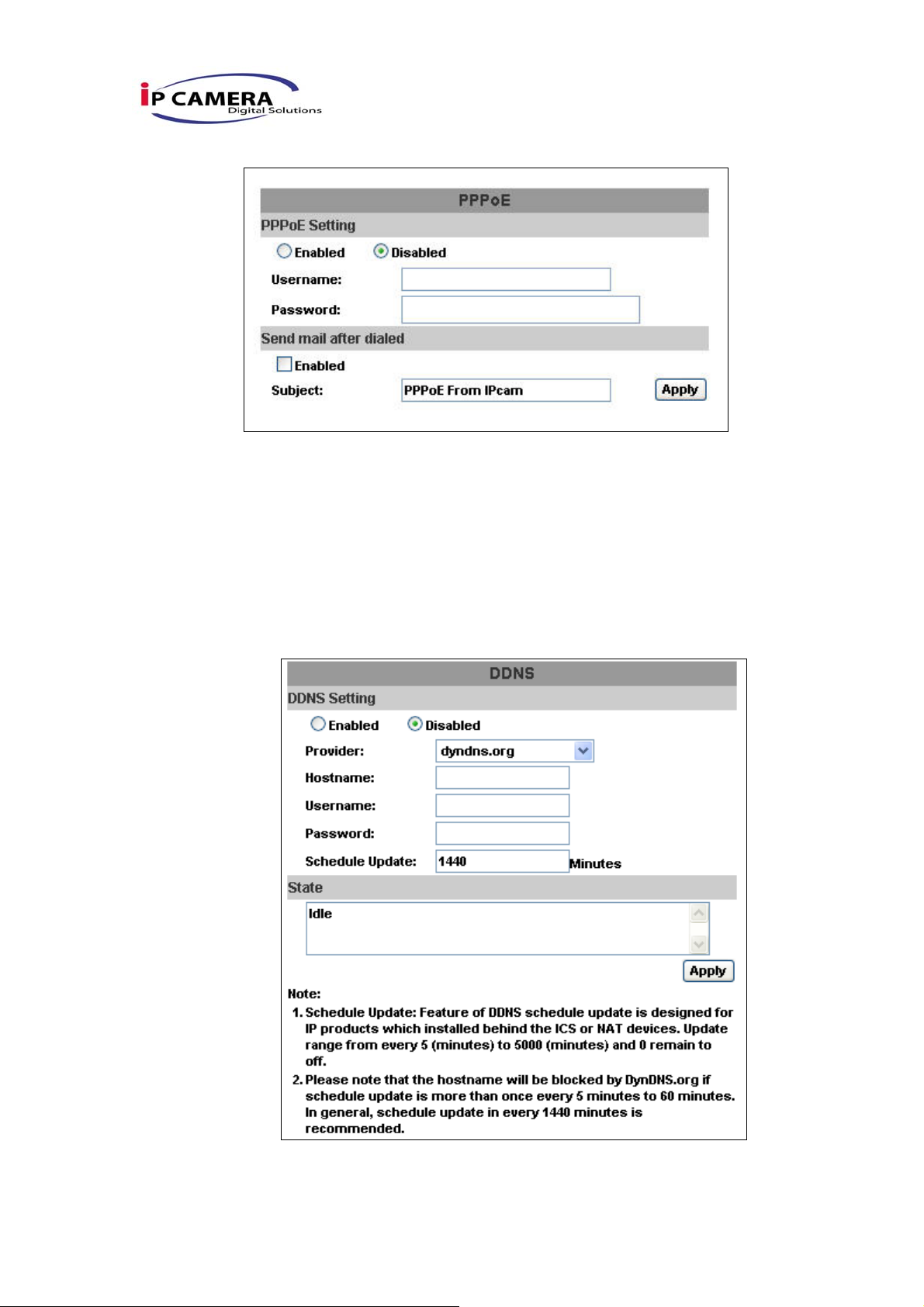
ii、 PPPoE:
Select “Enabled” to use PPPoE.
Key-in Username and password for the ADSL connection.
Send mail after dialed:When connect to the internet, it will send a mail
to a specific mail account. For the mail setting, please refer to “Mail and
FTP” settings.
iii、 DDNS:
Video Server supports DDNS (Dynamic DNS) service.
a. DynDNS:
1. Enable this service
2. Key-in the DynDNS server name, user name, and password.
25/42
Page 24
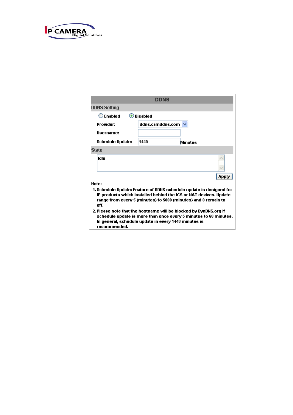
3. Set up the IP refreshing rate.
4. Click “Apply”
5. If setting up IP schedule update too frequently, the IP may be
blocked. In general, schedule update every day (1440 minutes)
is recommended.
b. Camddns service:
1. Please enable this service
2. Key-in user name
3. IP Schedule update is default at 5 minutes
4. Click “Apply”.
c. DDNS Status
1. Updating:Information update
2. Idle:Stop service
3. DDNS registration successful, can now log by
http://<username>.ddns.camddns.com:Register successfully.
4. Update Failed, the name is already registered:The user name
has already been used. Please change it.
5. Update Failed, please check your internet connection:Network
connection failed.
6. Update Failed, please check the account information you
provide:The server, user name, and p assword may be wrong.
26/42
Page 25
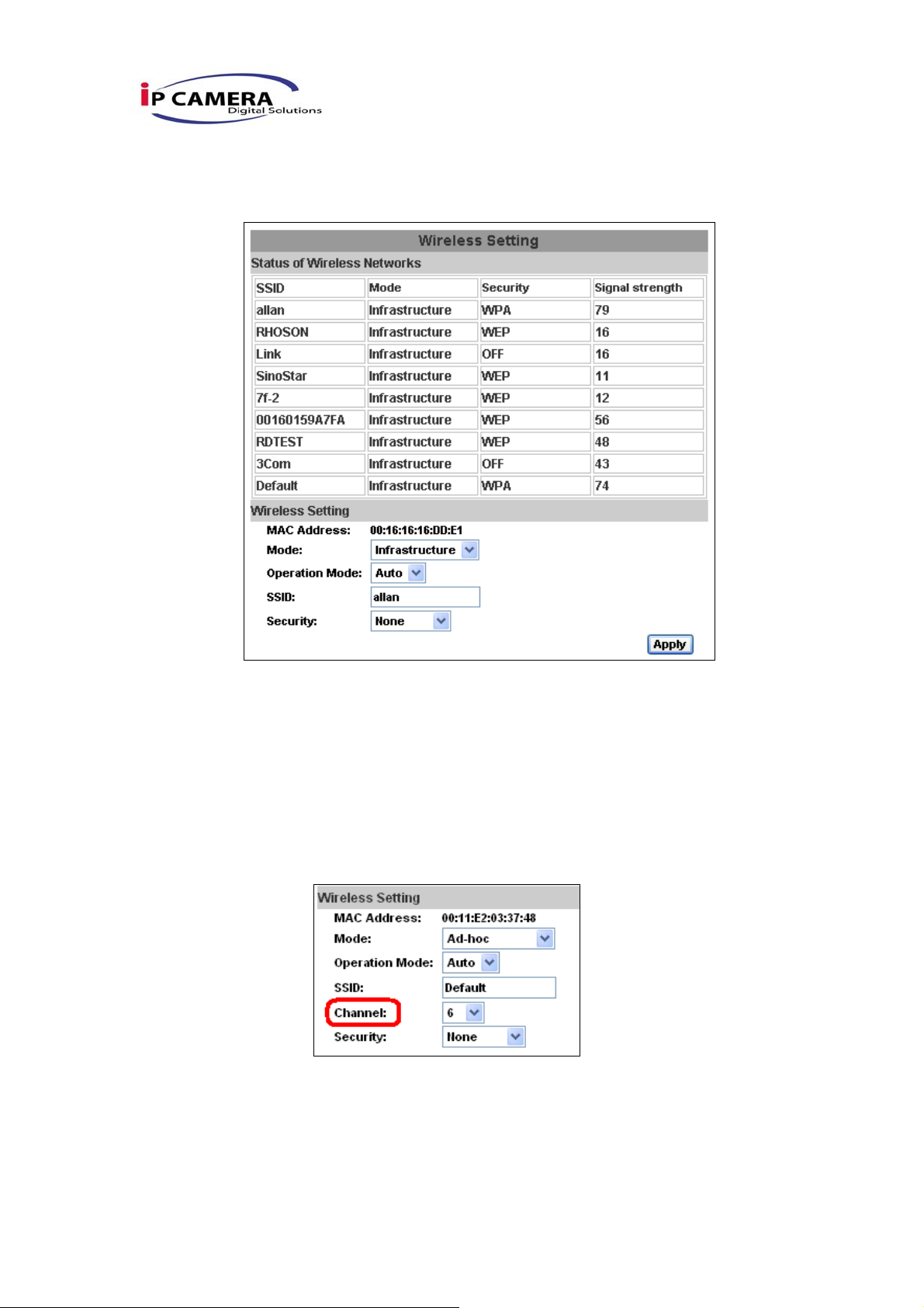
iv、 Wireless Setting (Wireless Network Optional)
Supports 802.11 b/g wireless connection.
Notice:Wireless network and Ethernet network use the same IP , the user has to unplug Ethernet
cable, if Ethernet cable is not unplug, wireless setting can not be executed.
a. Status of Wireless Networks:
scan all wireless services.
b. Wireless Setting:
1. Mode:There are Infrastructure and Ad-hoc. Infrastructure is for
connecting with the router. Ad-hoc is for connecting with PC.
There is “Channel” to select only when user uses Ad-hoc
mode.
e.g. If one PC’s channel is 1, the other’s channel has to 1, too.
2. SSID:Based on AP setting.
3. Channel:This is only be used when the user selects Ad-hoc
mode in order to avoid conflict.
4. Security:It supports “None”, “WEP”, “WPA-PSK” security
encryption based on the setting of the Router.
27/42
Page 26
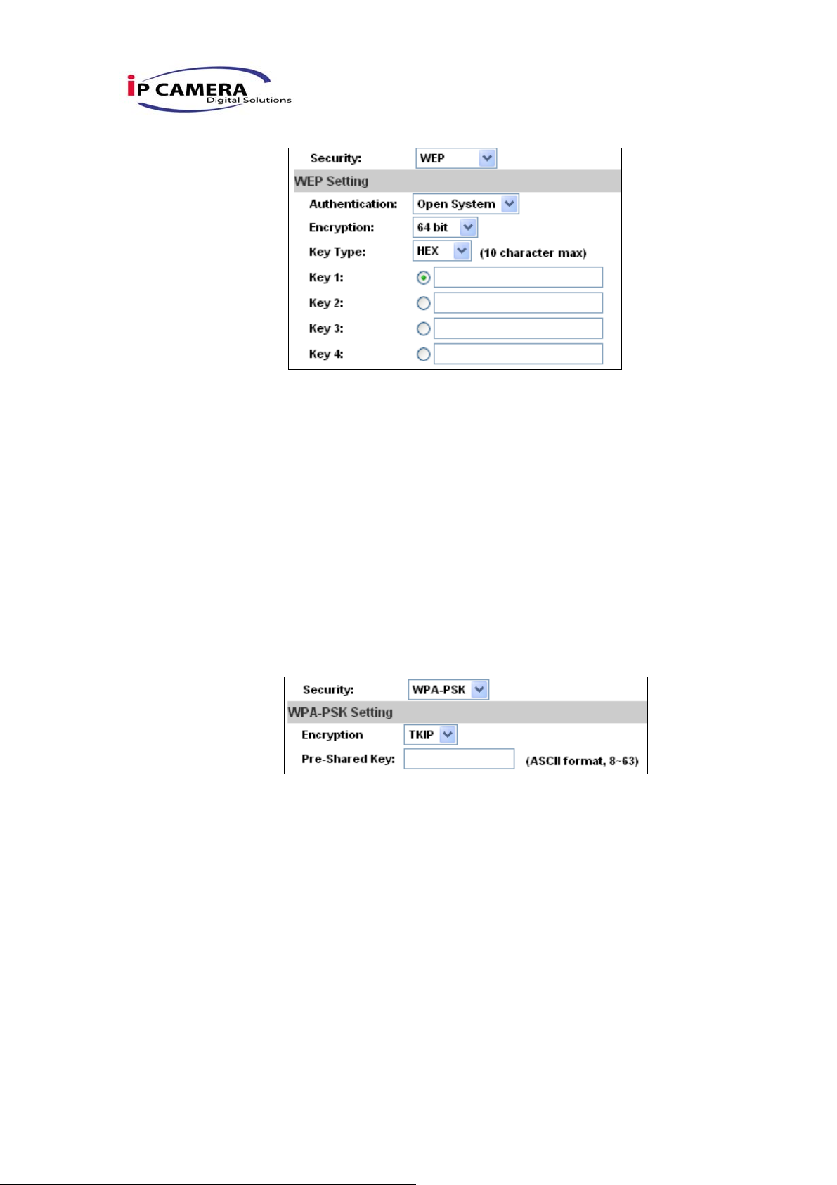
5. WEP:
z Authentication:There are Open System and Shared Keys,
it is based on different encryptions. This has to be the
same as the Router’s setting.
z Encryption:There are 64 bits and 128 bits. This is based
on Key Type based on the Router’s setting.
z Key Type:There are HEX and ASCII. When selecting HEX,
the user only can input 0~9 characters and use A, B, C, D,
E, and F.
z When selecting ASCII, the user can input any character.
(Case sensitive)
z Key 1~4:Based on Key Type to input characters.
6. WPA-PSK
z Encryption:There are TKIP and AES.
z Pre-Shared Key:Allow any characters. (Case sensitive)
28/42
Page 27
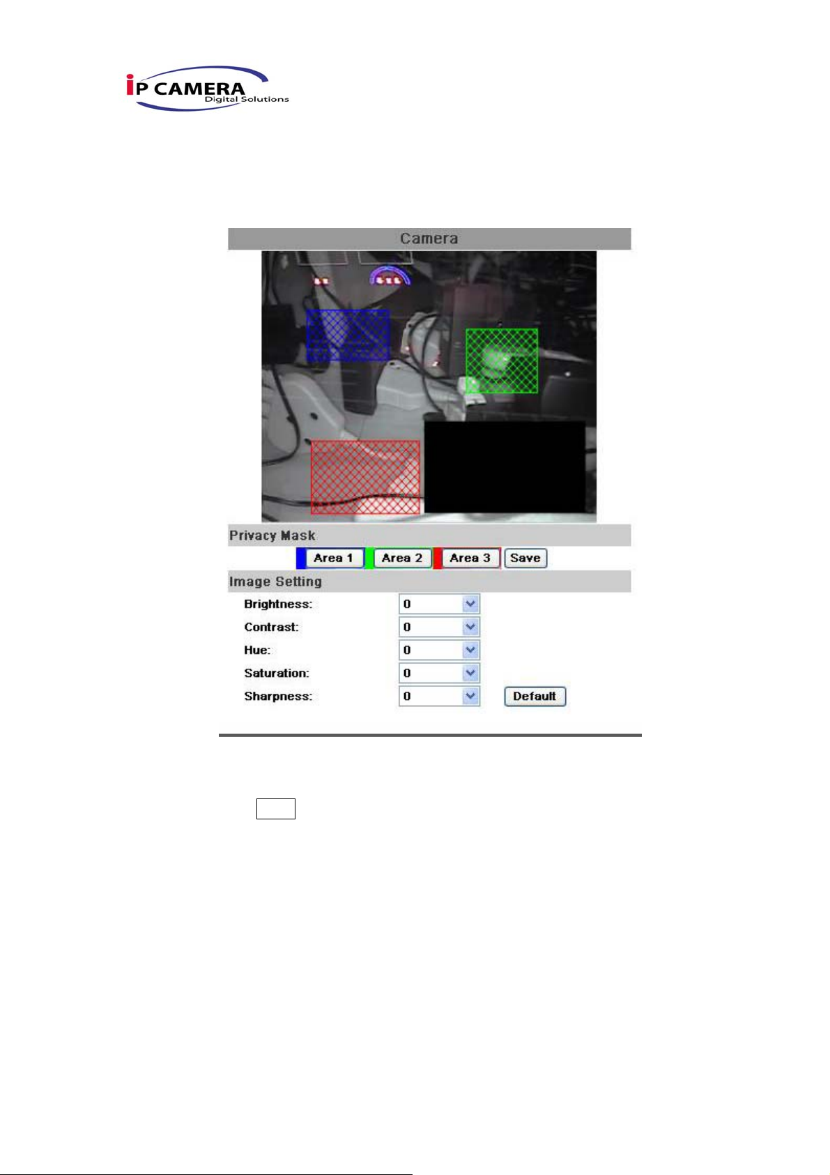
C.A/V Setting
i、 Image Setting
For the security purpose, there are three areas can be setup for privacy
mask. Click Area button first and pull a area on the above image. Finally,
click Save button to reserve the setting.
Adjust “Brightness”, “Contrast”, “Hue”, “Saturation” to get clear video.
ii、 Video Setting
User may select 3 streaming output simultaneously:
Streaming 1 Setting: Basic mode and Advanced mode
Streaming 2 Setting: Basic mode, Advanced mode
3GPP Streaming Setting
a. Streaming 1 Basic Mode:
29/42
Page 28
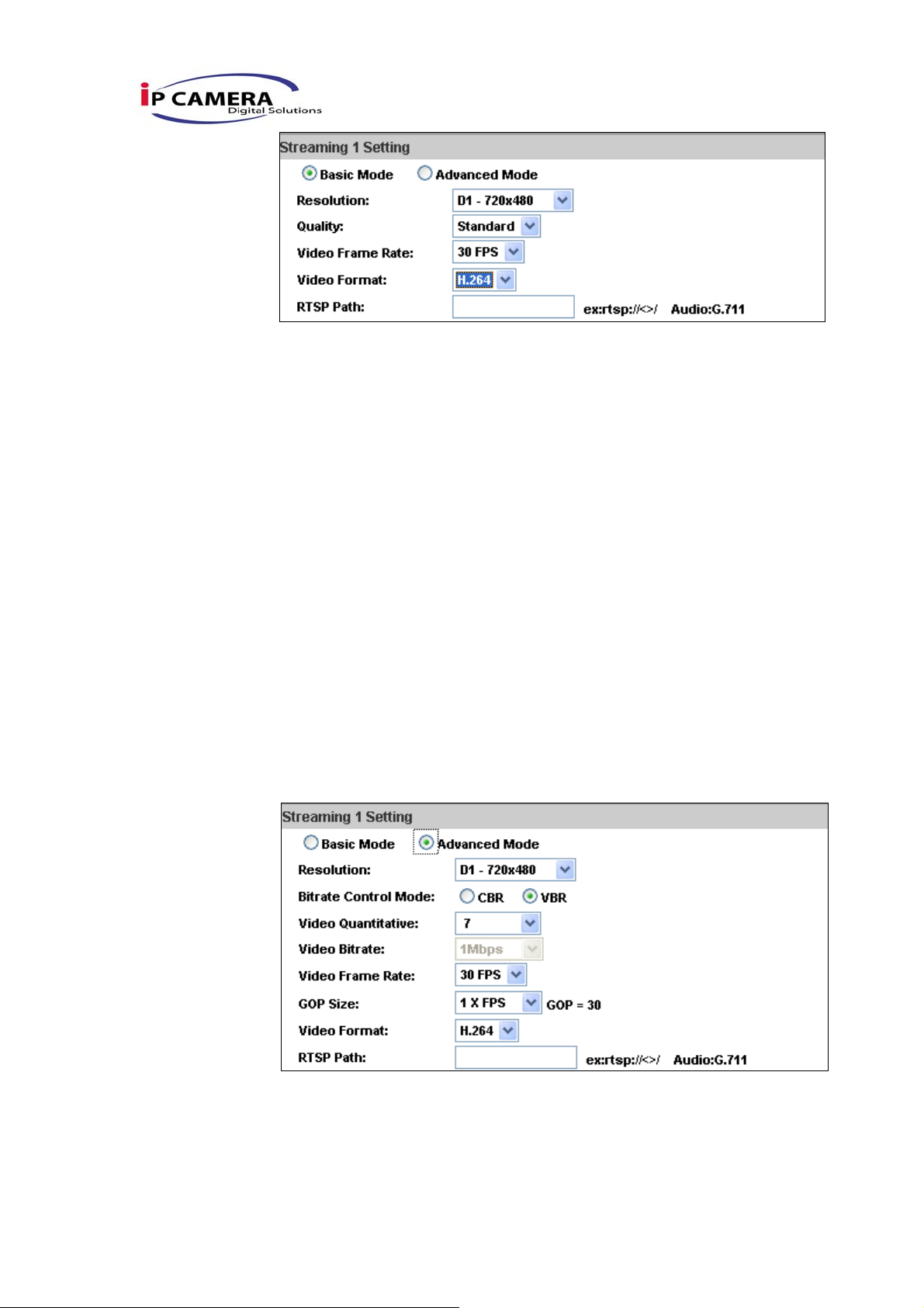
1. Resolution:
There are 4 resolutions to choose.
NTSC / PAL
D1 – 720×480 / 720×576
4CIF – 704×480 / 704×576
CIF – 352×240 / 352×288
QCIF – 176×120 / 176×144
2. Quality:
There are 5 levels to adjust:
Best/ High/ Standard/ Medium/ Low
The higher the quality is, the bigger the file size is.
Also not good for internet transmitting
3. Video Frame Rate:The video refreshing rate per second.
4. Video Format:H.264 or MJPEG.
5. RTSP Path: RTSP output name
b. Streaming 1 Advanced Mode:
1. Resolution:
There are 4 resolutions to choose.
NTSC / PAL
30/42
Page 29
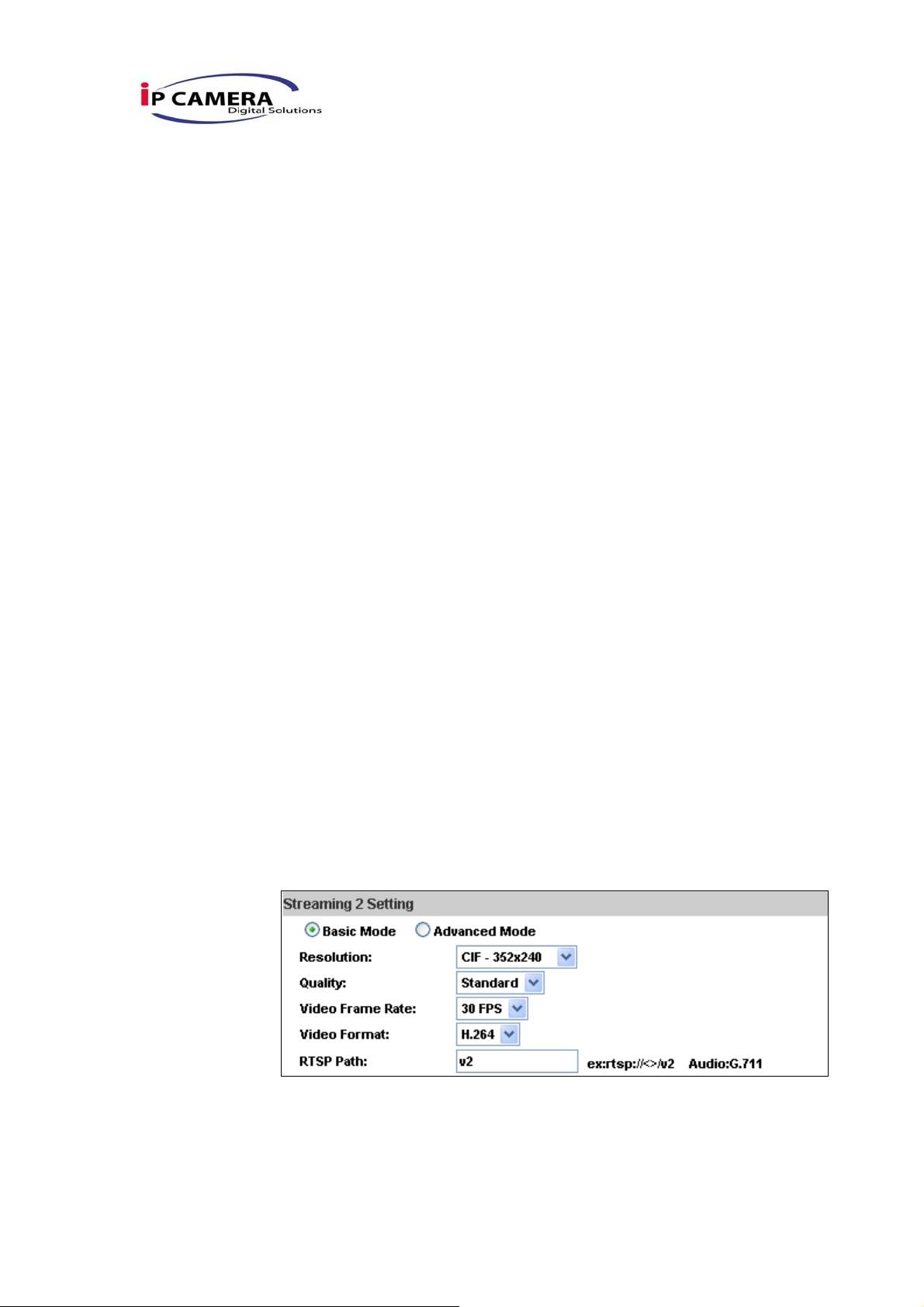
D1 – 720×480 / 720×576
4CIF – 704×480 / 704×576
CIF – 352×240 / 352×288
QCIF – 176×120 / 176×144
2. Bitrate Control Mode
There are CBR﹝Constant Bit Rate﹞ and VBR﹝Variable Bit
Rate﹞to use.
CBR:32Kbps~4Mbps – Increase CBR to increase the picture
qulity; vise versa
VBR:1(Low)~10(High) – Compression rate, the higher the
compression rate, the lower the picture quality is; vise versa.
The balance between VBR and network bandwidth will affect
picture quality. Please carefully select the VBR rate to avoid
picture breaking up or lagging.
3. Video Frame Rate
Picture display frame per second
NTSC: Max 30 frames/second PAL: Max 25 frames/second
4. GOP Size
It means "Group of Pictures". The higher the GOP is, the better
the quality is.
5. Video Format:
There are 2 Video Format to choose
H.264 or MJPEG.
6. RTSP Path: RTSP output connecting route
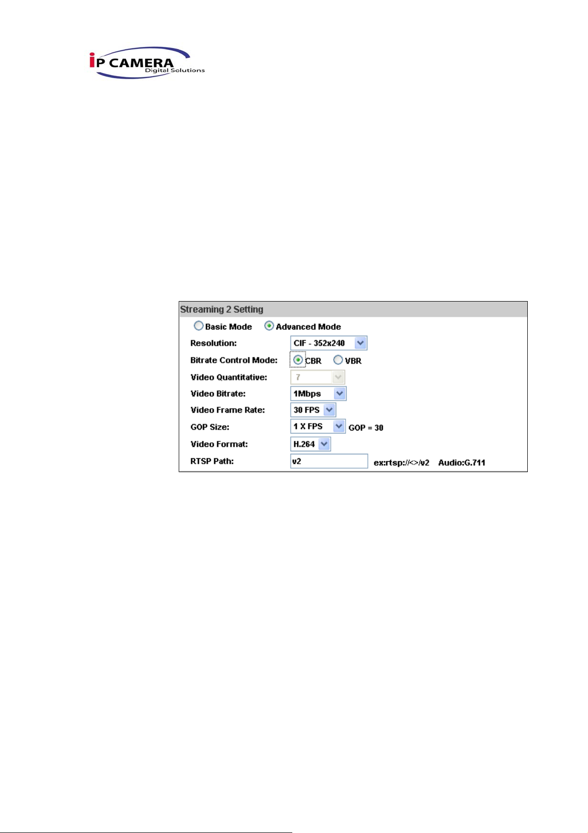
c. Streaming 2 Basic Mode:
1. Resolution:
There are 4 resolutions to choose.
NTSC / PAL
D1 – 720×480 / 720×576
31/42
Page 30
4CIF – 704×480 / 704×576
CIF – 352×240 / 352×288
QCIF – 176×120 / 176×144
2. Quality:
There are 5 levels to adjust:
Best/ High/ Standard/ Medium/ Low
The higher the quality is, the bigger the file size is. Also not
good for internet transmitting
3. Video Format:H.264 or JPEG
4. RTSP Path: RTSP output connecting route
d. Streaming 2 Advanced Mode:
1. Resolution:
There are 4 resolutions to choose.
NTSC / PAL
D1 – 720×480 / 720×576
4CIF – 704×480 / 704×576
CIF – 352×240 / 352×288
QCIF – 176×120 / 176×144
2. Bitrate Control Mode
There are CBR﹝Constant Bit Rate﹞ and VBR﹝Variable Bit
Rate﹞to use.
CBR:32Kbps~4Mbps (the higher the CBR is, the better the
video quality is)
VBR:1~10 (Compression Rate)
3. Video Frame Rate
The video refreshing rate per second.
4. GOP Size
32/42
Page 31
It means "Group of Pictures". The higher the GOP is, the better
the quality is.
5. Video Format:H.264 or JPEG
6. RTSP Path: RTSP output name
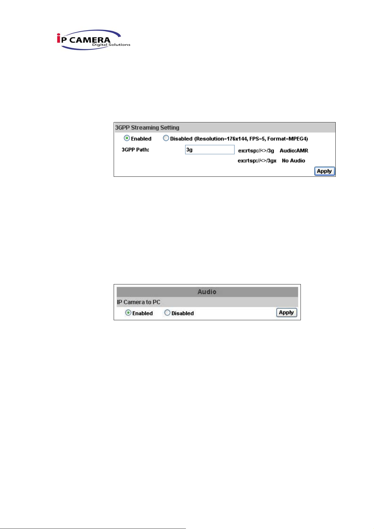
e. 3GPP Streaming Setting mode:
3GPP default value is Resolution=176x144, 5FPS,Format=MPEG4
1. Enable or Disable 3GPP Streaming
2. 3GPP: 3GPP output name
iii、 Audio:
Video Server supports 2-way audio.
a. From video server to local PC, select “Enable” to start this function
(When enabled, you can send audio via external mic in the IP
Camera)
33/42
Page 32
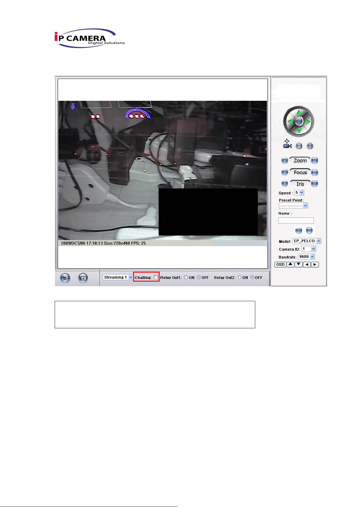
b. From local PC to Video Server, check “chatting” in the browsing
page (You will need a mic to send audio from local PC to IP
Camera)
The Audio will not be smooth when enable SD card
recording function simultaneously.
34/42
Page 33
D.Event List
Video Server provides multiple event settings.
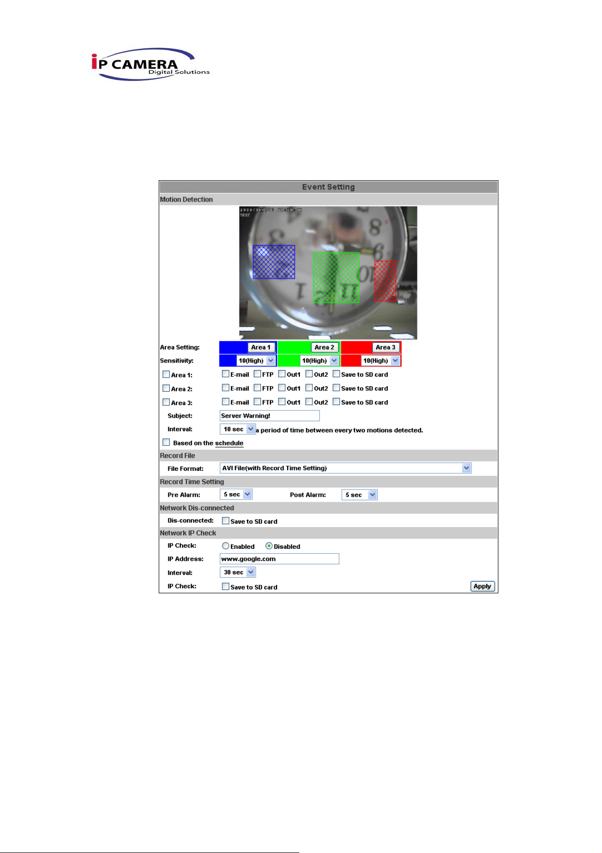
i、 Event Setting
a. Motion Detection:
Video Server allows 3 areas motion detection. When motion is
triggered, it can send the video to some specific mail addresses,
transmit the video to remote ftp server, trigger the relay, and save
video to local SD card. To set up the motion area, click “Area
Setting”. Using mouse to drag and draw the area. The same
operation for area 2 and 3.
b. Record File Setting: IP CAMERA allows 3 different types of
recording file to change its record size.
When motion/alarm is triggered, there are 3 different types of
35/42
Page 34

record mode.
1. AVI File (With Record File Setting )
2. Multi-JPEG (With Record File Setting), only with JPEG
compression format.
3. Single JPEG (Single File with Interval Setting)
c. Record Time Setting:
Pre Alarm and Post Alarm setups for video start and end time when
motion detected, I/O, or other devices got triggered.
Note: Pre/Post Alarm record time is base on record time setting and IP Cam
built-in Ram memory. Limited by IP Cam built-in Ram Memory, When information
is too much or video quality set too high, it will cause recording frame drop or
decrease on post alarm recording time.
d. Network Dis-connected
When the network is down, it will save the video to local SD card.
This function is only enabled in wire connection.
e. Network IP check
When the connection is down, it records the video to SD card. Make
sure the video recording is continuous. To use this function, key in
the IP address of the PC which has recording software installed.
Enable the function of “Save to SD card”, then click “Apply”.
The interval of two video files on SD card is fixed with 30
seconds.
ii、 Schedule
a. Schedule: After complete the schedule setup, the camera data will
be recorded according to the schedule setup.
b. Snapshot: After enable the snapshot function, user can select the
storage position of snapshot file, the interval time of snapshot and
the reserved file name of snapshot.
36/42
Page 35
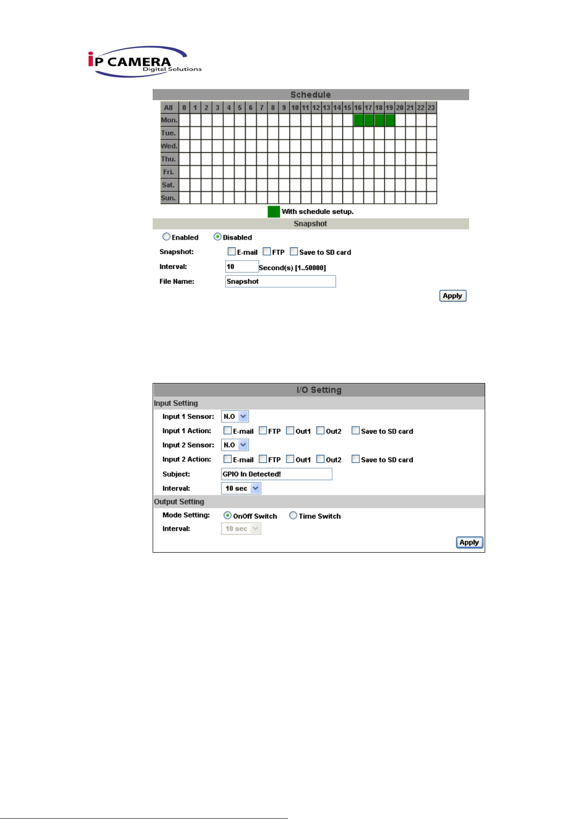
iii、 I/O Setting
Video Server supports 2 input/ 2 Relay output. When input is triggered, it
can send the video to some specific mail addresses, transmit the video
to remote ftp server, trigger the relay, and save video to local SD card.
iv、 Mail & FTP
To send out the video via mail of ftp, please set up the configuration first.
37/42
Page 36
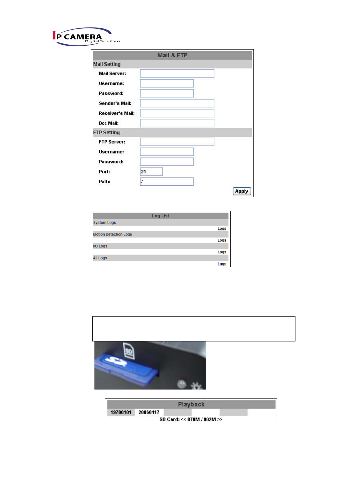
v、 Log List
Sort by System Logs, Motion Detection Logs and I/O Logs. In addition,
System Logs and I/O Logs won’t lose data due to power failure.
vi、 SD card
Please Insert SD card before use it. Make sure pushing SD card into the
slot completely.
Note:The use of the SD card will affect the operation of the
Video Server slightly, such as affecting the frame rate of the
a. Playback:
1. It will show the capacity of the SD card. Click the date listed on
this page. It will show the list of the video.
38/42
Page 37
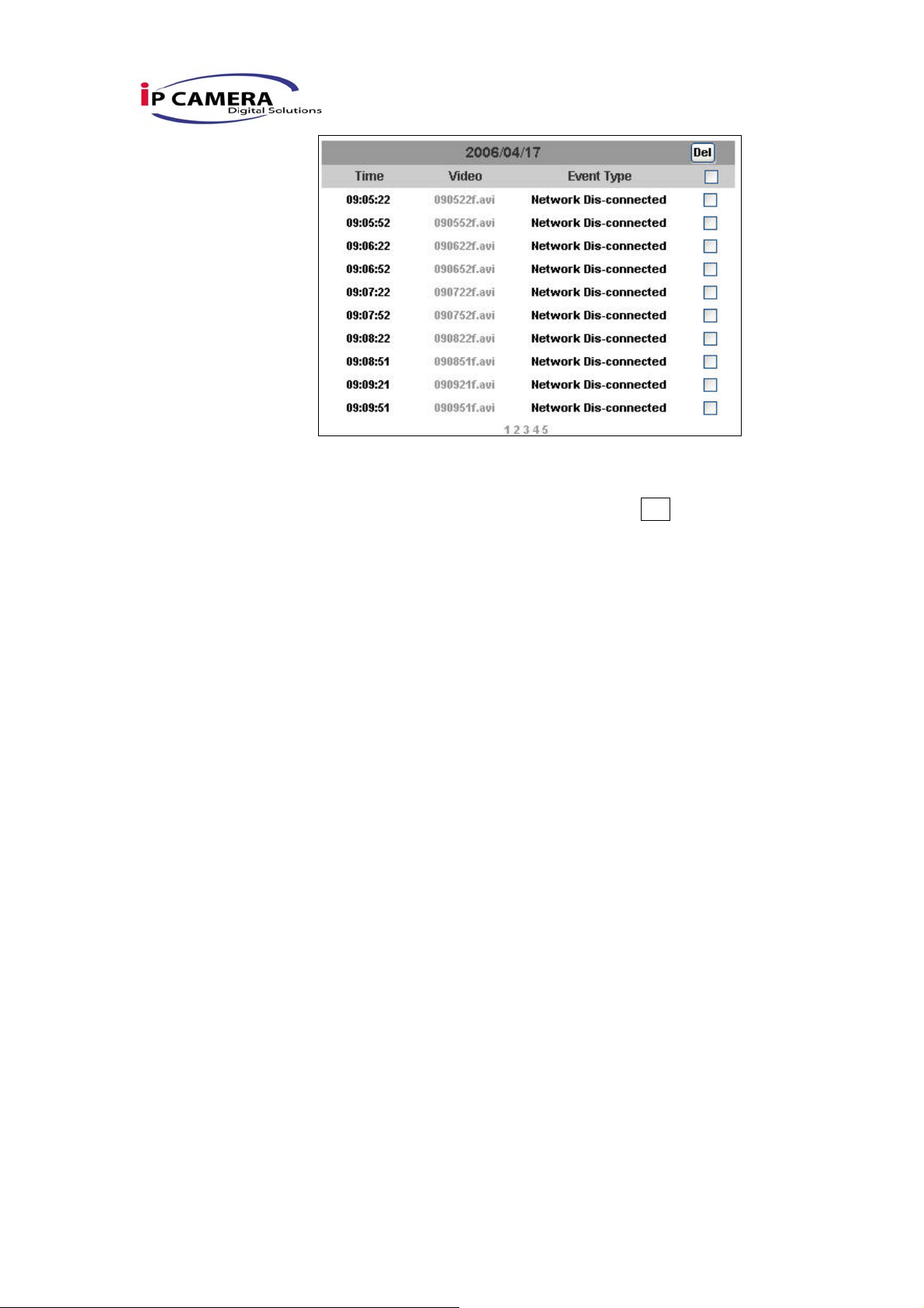
2. The video format is AVI. Click the video to start Microsoft Media
Player to play it.
3. To delete the video, check it, then click Del. When the SD card
is full, it will remove the oldest video automatically.
39/42
Page 38
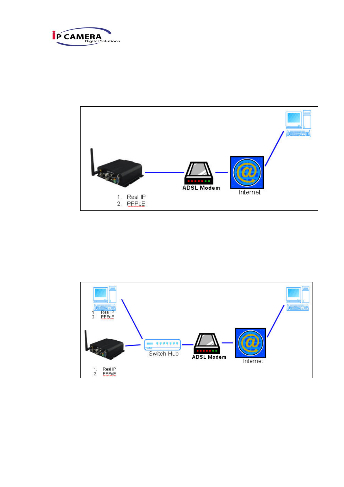
VI. Network Configuration
i、 Configuration 1:
A. Internet Access:ADSL or Cable Modem
B. IP address:One real IP or one dynamic IP
C. Only Video Server connects to the internet
D. For fixed real IP, set up the IP into Video Server. For dynamic IP, start
PPPoE.
ii、 Configuration 2:
a. Internet Access:ADSL or Cable Modem
b. IP address:More than one real IP or one dynamic IP
c. Video Server and PC connect to the internet
d. Device needed:Switch Hub
e. For fixed real IP, set up the IP into Video Server and PC. For dynamic
IP, start PPPoE.
40/42
Page 39
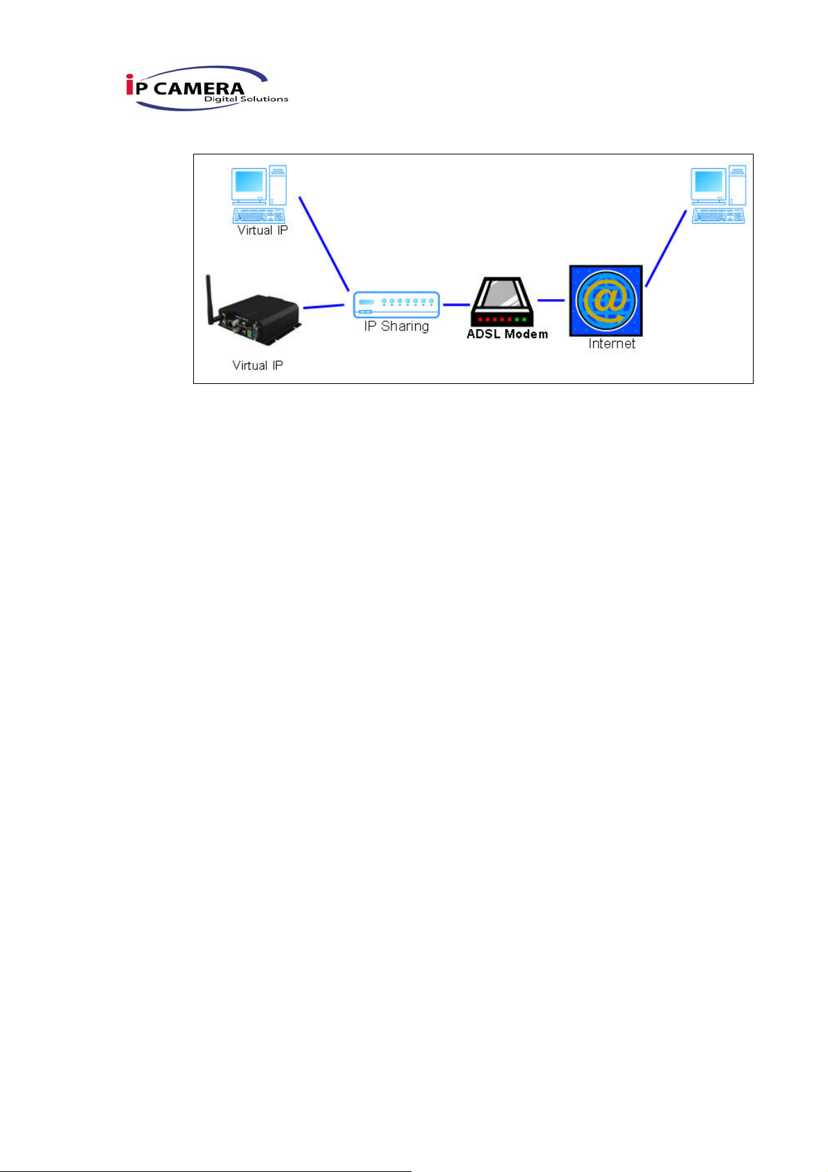
iii、 Configuration 3:
a. Internet Access:ADSL or Cable Modem
b. IP address:one real IP or one dynamic IP
c. Video Server and PC connect to the internet
d. Device needed:IP sharing
e. Use virtual IP, set up port forwarding in IP sharing.
41/42
Page 40
VII. Factory Default
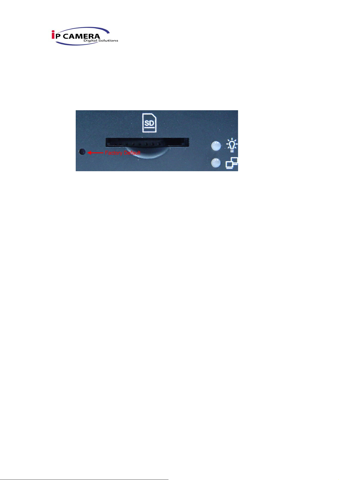
i、 To recover the default IP address and password, please follow the following
steps.
ii、 Remove power and press and hold the button in the back of Video Server.
iii、 Power on the Video Server. Don’t release the button during the system
booting.
iv、 It will take around 30 seconds to boot the Video Server.
v、 Release the button when Video Server finishes proceed.
vi、 Re-login the Video Server using the default IP (http://192.168.1.210), and
user name (admin), password (admin).
VIII. Package contents
i、 Video Server
ii、 Adaptor
iii、 Ethernet Cable
iv、 CD title (User manual, IP installation Utility)
Appendix I
SD Card Recommended:
SanDisk 128M
SanDisk 256M
SanDisk 512M
SanDisk 1G
SanDisk 2G
SanDisk 4G
Transcend 128M 80X
Transcend 256M 80X
Transcend 512M 80X
Transcend 1G 80X
Transcend 2G 80X
Transcend 4G 80X
42/42
 Loading...