

Page 1

Wireless/Wired Network IP Camera
(For PC View)
Night Vision & Remote
Operation
User
Manual
0
Page 2

Thank you for buying our IP camera
IPCAM AJ Series IP Camera products are designed and equipped for local and remote
network video surveillance system, including wired IP bullet camera, wireless IP bu
ll
et
camera, IP IR dome camera, IP IR waterproof camera, IP Pan/Tilt/Zoom Camera etc. We
adopt high performance chip to ensure high quality media processor which processes
audio and video collection, compression and transmission. Standard M-JPEG
compress
i
on format ensures clear and streaming video performance. It enables users to
view live video via IE6.0, IE7.0, IE8.0, Firefox, Google browser or other standard browser
IPCAM AJ series IP Camera products are applicable for big, medium-sized and small
enterprises, chain store, factory, home and all kinds of spots where remote network video
transmission and control supposed to be installed, they are easy to be installed and
operated. Before the installation of the IP camera, please check if your product
accessor
i
es in the package are comp
l
ete
Packing List
Untie the pack and check the items contained against the following
list:
●IP Camera X1
●Warranty Card X1
●DC Power Supply X1
●CD X1
●Certificate of Quality X1
●Mounting bracket X1
NOTE: Please contact us immediately if anything damaged or short of contents
.
1
Page 3

Table of CONTENTS
1. Product Introduction
...........................................................................................3
1.1. Safety Introduction
.........................................................................................3
1.2. Product Specifications....................................................................................
....3
1.3. System
Requirements........................................................................................3
1.4. Product
Views……………..............................................………….................4
1.4.1 Fro nt View ..... ... ... .....
......................................................................................4
1.4.2 Interface
View.................................................................................................5
1.5. Hardware
Installation........................................................................................5
1.6. Software Installation.....................................
....................................................6
2. Software
Operation...............................................................................................6
2.1. Search Tool Software.............................................. ...
......................................6
2.1.1. Search The IP address of the
Camera.............................................................6
2.1. 2. Configuration of the Network............................
............................................7
3. Real-Time Video Demonstration...................................
......................................9
3.1. Camera Login.............................................................. ..................
...................9
3.2. View via IE
Browser.........................................................................................10
3.3. View via Safa ri, Firef ox , Googl e Bro wser . ... ...... ...... ...
...................................13
3.4. Main Menu int erface Introduction.......
............................................................14
3.5. Administer Setting Instruction.........................
................................................15
3.5.1. Multi-Device
Settings....................................................................................16
3.5. 2. Basic Network Settings.......... ....
...................................................................17
3.5.3. Wireless Settings..........................................................
.................................17
3.5.4. Dy n amic DNS
Settings...................................................................................18
3.5. 4.1. DDNS Set tin g
.............................................................................................18
3.5.4.2. Port Forwarding Settings.........
...................................................................20
3.5.4.3. DDNS Register........ ..................
................................................................23
3.5.5. Email and FTP Service Settings.......................
.............................................28
3.5.6. Alarm Service Settings.............................
.....................................................29
3.5. 7. Reset/ Firmware Upgrade Settings...............
..................................................29
3.5.8. Record&Capture Path..........................
..........................................................30
3.5.9. Reset/Firm Ware
Upgrade...............................................................................30
3.5.9.1.Restore Factory
Settings................................................................................31
3.5.9.2. Reboot
Equipment........................................................................................31
4.
Warranty................................................................................................................31
2
Page 4

1. Product
Introduction
1.1 Safety Instructions
(1). Use the proper power
source.
Do not use this product with a power source that supplies more than the specified Vo
l
tage
(100-240V AC)
.
(2). Never insert anything metallic into the
camera.
Inserting metal object into the camera can be a source of dangerous electric shock
.
(3). Do not operate in wet or dusty
environment.
Avoid places like a damp basement or dusty hallway
.
(4). Do not attempt to disassemble the
camera.
You may be subjected to severe electrical shock if you attempt to take apart the camera
while the camera is connected to its power source. If there are any unusual sounds or
smells coming form the camera, unplug it immediately and contact Customer Serv
i
ce
.
(5). Handle the camera
carefully
Dropping the camera on any hard surface may cause a malfunction. If the camera does not
work properly due to physical damage, please contact Customer Service for repair or
exchange
.
(6). Apply to FCC and CE
Rule
This device complies with part 15 of the FCC and CE Rules. Operation is subject to the
following two cond
iti
ons:
1: This device may not cause harmful
i
nterference
.
2: This device must accept any interference received, including interference that may
cause undesired operat
ion.
Any changes or modifications not expressly approved by the party responsible for
compliance could void the user’s authority to operate the equipment. This equ
i
pment
complies with FCC and CE radiation exposure limits set forth for uncontro
ll
ed
env
i
ronment. This equipment should be installed and operated with minimum distance 20
cm between the radiator & your body
.
This transmitter must not be co-located or operating in conjunction with any other antenna
or transm
i
tter
.
1.2. Product Specifications
*- Adopt high Performance, strong function media processor 32Bit RS
I
C
*- High sensor CMOS
*-Adopt optimized MJPEG video compression algorithm, realize high-definition
i
mages
transmission in narrow bandw
i
dth;
3
Page 5
*-Maximum support 15 users viewing at the same time, no limit for users if using forwarder
Server funct
i
on;
*- Built in Web Server, convenient for users to use standard browse to realize the
real time monitoring and setting adm
ini
strat
i
on;
*-Support WIFI:802.11 b/g/n wireless network
i
ng;
*-Support remote system update;
*-Support DDNS analysis, support LAN & Internet (ADSL,Cable Modem)
*-Support variety of network protocol: TCP/IP, UDP, SMTP, PPPoE, Dynamic DNS
,
DNS Client, SNTP, BOOTP, DHCP, FTP, SNMP, WIFI/802. 11b
/
g
*-Parts of modes products support one/ two way audio, ta
l
kback;
*-Support motion detection alarm function (area & sensitivity Conf
i
gurab
l
e);
*-Support image snapshot
*-Abnormal automatic recovery function, auto reconnection available when network
Interruption occurred
.
*-Dynamic alarm function, alarm time-schedule conf
i
gurable
.
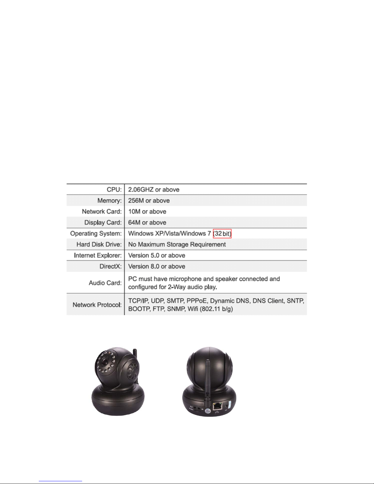
1.3. System Requirements
1.4. Product Views
1.4.1 Front View 1.4.2 Interface
View
4
Page 6

Figure 1.1 Figure 1
.
2
1: Audio Out , 2: Audio
I
n
3: Ethernet interface: RJ-45 interface. Power Supply Light: constant on after power up
Network light: constant sparkle after power up data transm
ission.
4: Antenna:
5: Power input interface: connect direct current 5V Power
1.5 Hardware Installation
Follow the steps below to set up your camera hardware. Make sure to follow each step
carefully to ensure that the camera operates proper
l
y
1. Install the Wi-Fi antenna (For wireless model)
.
2. Plug the power adaptor into camera
3. Plug the network cable into camera, the other side to the router
/swi
tch
4. It takes approx 30 seconds to boot up the camera, then you will find the IP address from
“Search Tool” (Figure: 1
.
8)
5. When the power on and network cable connected, the green led of the real panel w
ill
keep on, The yellow led will keep flash
.
5
Page 7
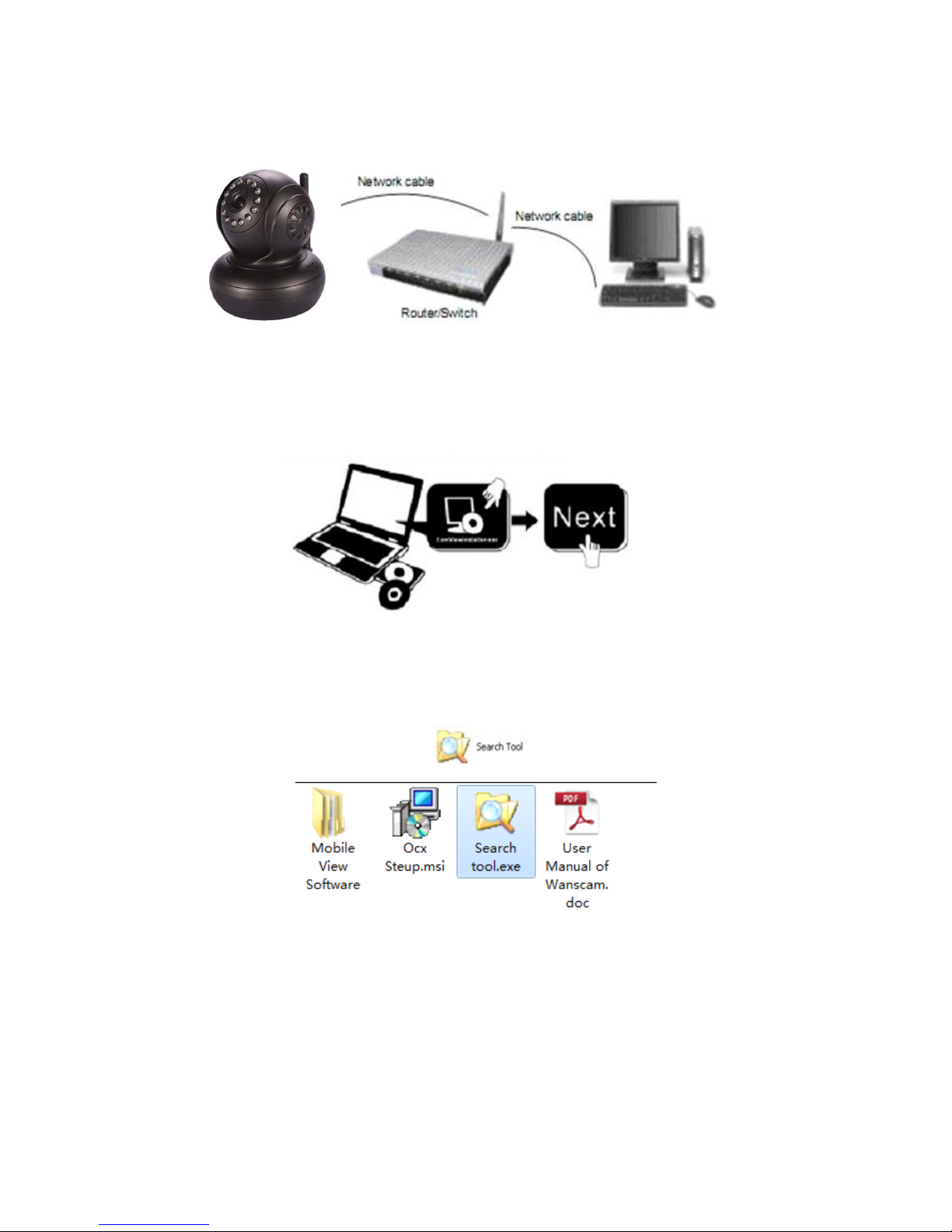
Figure 1.3
1.6 Software Installation
Figure 1.4
Open the CD Install the follow software:
1. ActiveX: Click “OCX setup”—“Next”—“Install”—“Finish”
.
2. Search Tool: Open the CD, click
,The Search Tool will run
automatically.( No need to install. You can copy this software to your desktop
.
)
Figure 1.5
6
Page 8
Makesu
r
e
the “SubnetMask”
your
u
r
rent
compute
r
s
“DNS Server”
isthesam
e
2. Software operat
i
on
2.1 Search Tool Software
2.1.1 Search the IP address of the
camera
.
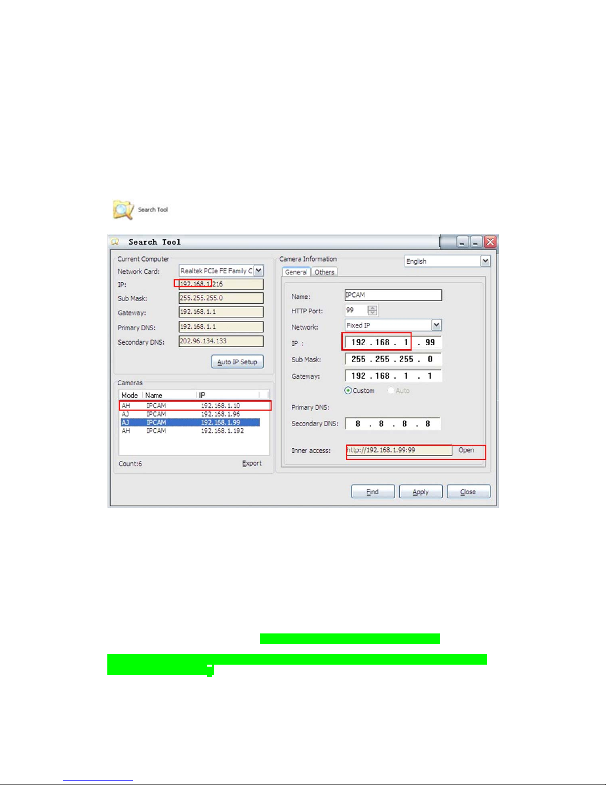
When the device has been mounted properly, you can double click the
I
con
“
” run this IP address search too
l.
Figure 2
.
1
Note: The software searches IP Servers automatically over LAN
.
There are 2 cases:
1. No IP Cameras found within LAN. After about 1 minute search, the Equipments L
i
st
Field not show the IP address
.
2. IP Cameras have been installed within LAN. All the IP Cameras will be listed and the
total number is displayed in the Equipments list field as shown in Figure 2
.
1
Note:
1. Current Computer indicates the Comput er’s IP Addres s in
f
ormation.
2. Equipment information in dicates the IP camera’s IP Address in
f
ormation.
3. If you find that the camera’s “Subnet Mask”, “Gateway”, “DNS Server” is not as
some as your current computer’s. You need try to change the camra’s IP address
.
, “Gateway”
,
as your router’s or
7
Page 9

SubnetMask,Gatewa
y
,
DNS Serve
r
4. If you don’t know how to configure your camera’s IP address. You can c
li
ck
“ Update” button. The Search Tool software can help you configure a usable IP camera
automat
ically.
2.1.2 Configuration of the
Network
Once your camera’s IP address
’
is the same as your
PC or router, you need configure the camera’s Network parameter manua
lly.
IP address: Fill in the IP address assigned and make sure it is in the same subnet as
t
he
Gateway, and the subnet should be the same as your computer or router. (i.e. the first
t
hree
sections are the same)
Subnet Mask: The default subnet mask of the equipment is: 255.255.255.0. You can find
t
he
subnet mask from your PC or rou
ter.
Gateway:
Make su re it is in the same s ub n et wi th PC ’s IP add r ess .Here gate way is th e LAN IP
of your rou
t
er.
Primary DNS:
IP address of IPS network provider. You can also set it as the same as the
Ga
t
eway.
NOTE: Yo u can find out the Subnet Mask, Gateway, Primary DNS of your PC from
t
he
“Search To ol” so
ft
ware.
Http Port: LAN por t assigned for the e q uipm ent, de fault is 99. You ca n change the port number
to any one you want such as : 98,211,9999 e
t
c.
3: Real-time Video Demonstration
.
3.1. Camera
Login:
You can access the camera through IP Camera Tool or IE, Firefox, Safari, Google
Chrome or other standard browser directly.
1. Double click the IP address of the IP Camera listed (Figure 2.1). The default
browser you use will run automatically and come to the camera login interface.
(Figure 3.1 )
2. To access the camera by IE Browser directly, just type the camera’s IP address, for
example, if the camera’s IP address is 192.168.1.99:99:
8
Page 10
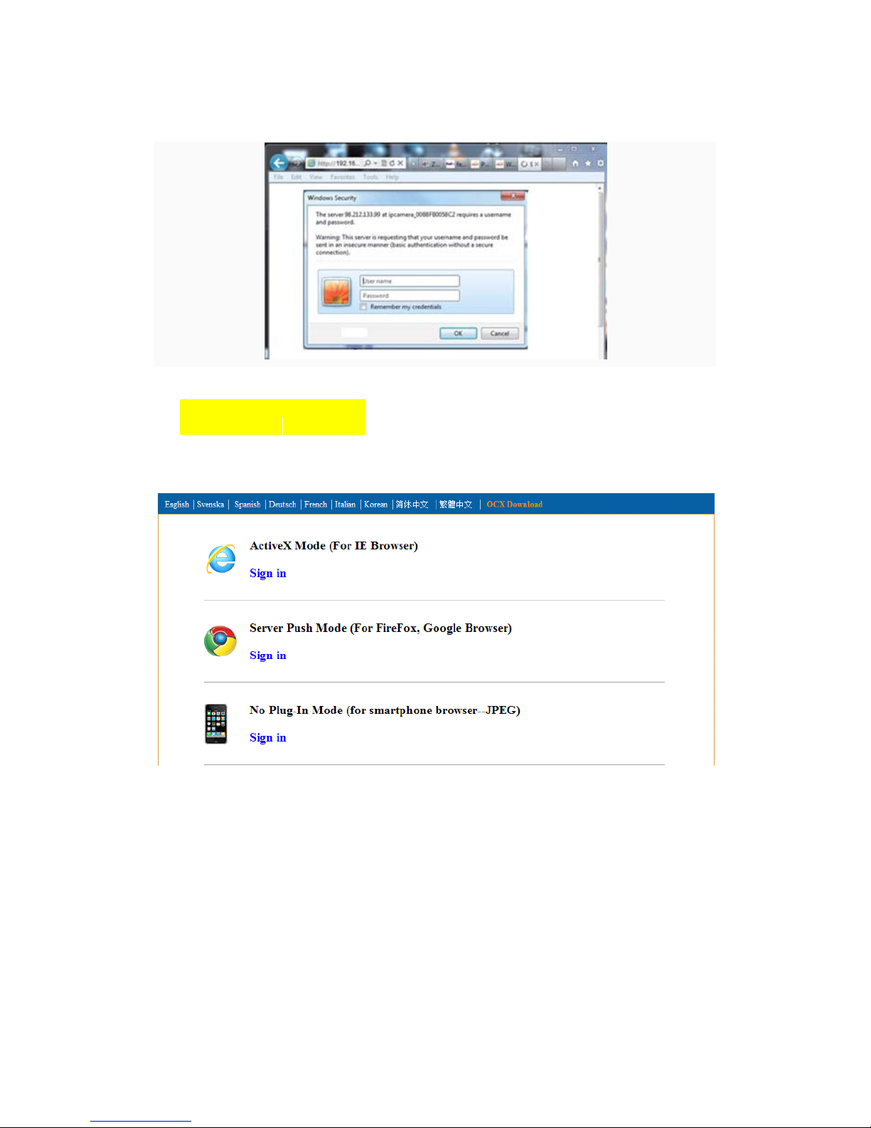
Figure 3.1
Defaultusername: admi
n
Password: nopassword.
Input the correct user name and password, the Sign In interface will pop-up.
There are three models to login (figure 3.2).
Figure 3
.
2
(1) ActiveX Mode (For IE Browser): available in IE6.0 or above explorer
(2) “RTSP Stream Mode”: available in Firefox, Safari, and Google browser.
(3) “No Plug-In Mode”: available in smart phone browser.
(4) SD card video playback online
3.2. View via IE
Browser.
9
Page 11
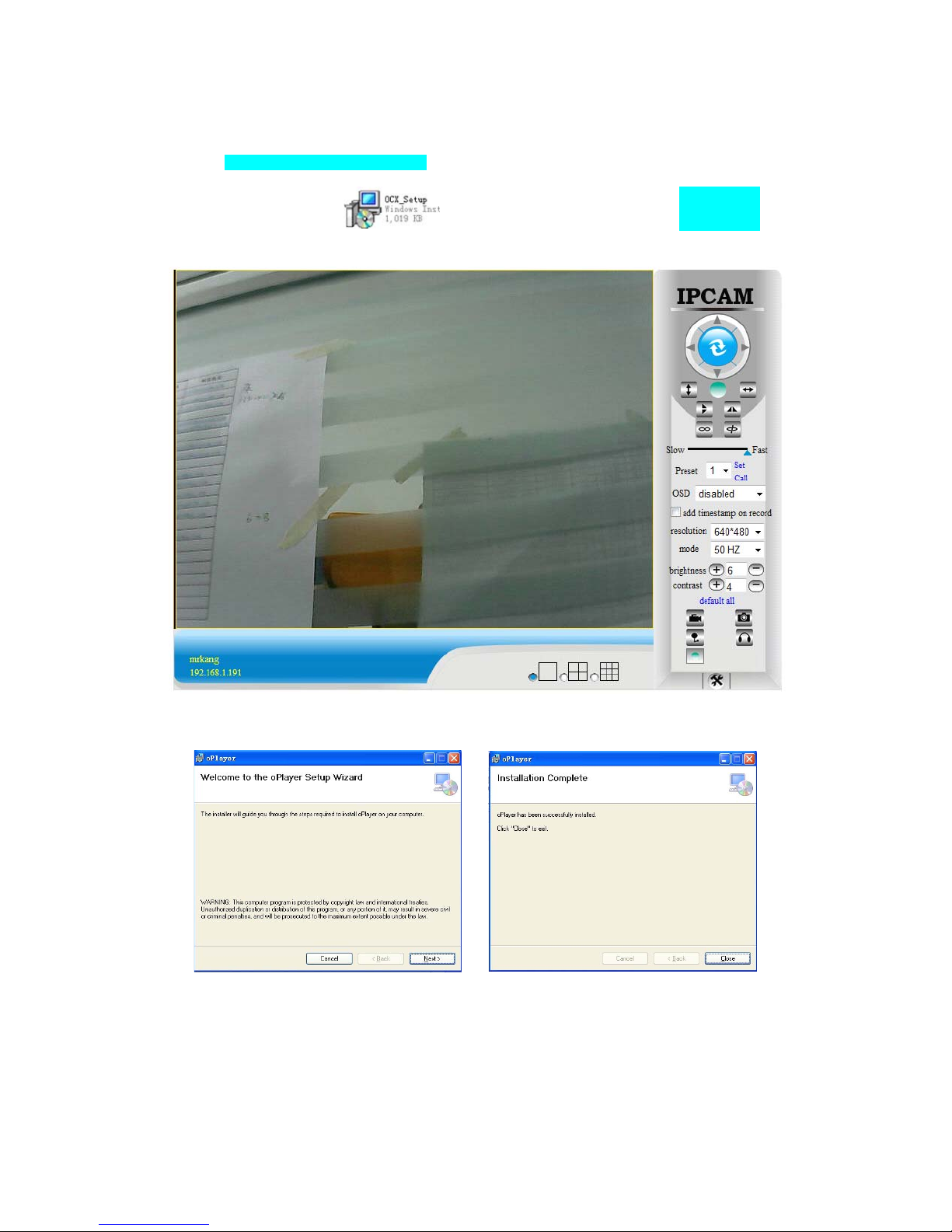
Choose Active Mode (For IE Browser), and sign in
.
The first time login the camera, maybe get ActiveX prompt as the picture below, p
l
ease
download the Ocx(or run
in CD) and install first then choose Run Add-on,
refresh and login the camera again, then will see live video, details as be
l
ow:
Figure 3
.
3
After Download Ocx-Setup (oPlayer Software), Click and install it, untill f
ini
shed
.
Figure 3
.
4
10
Page 12
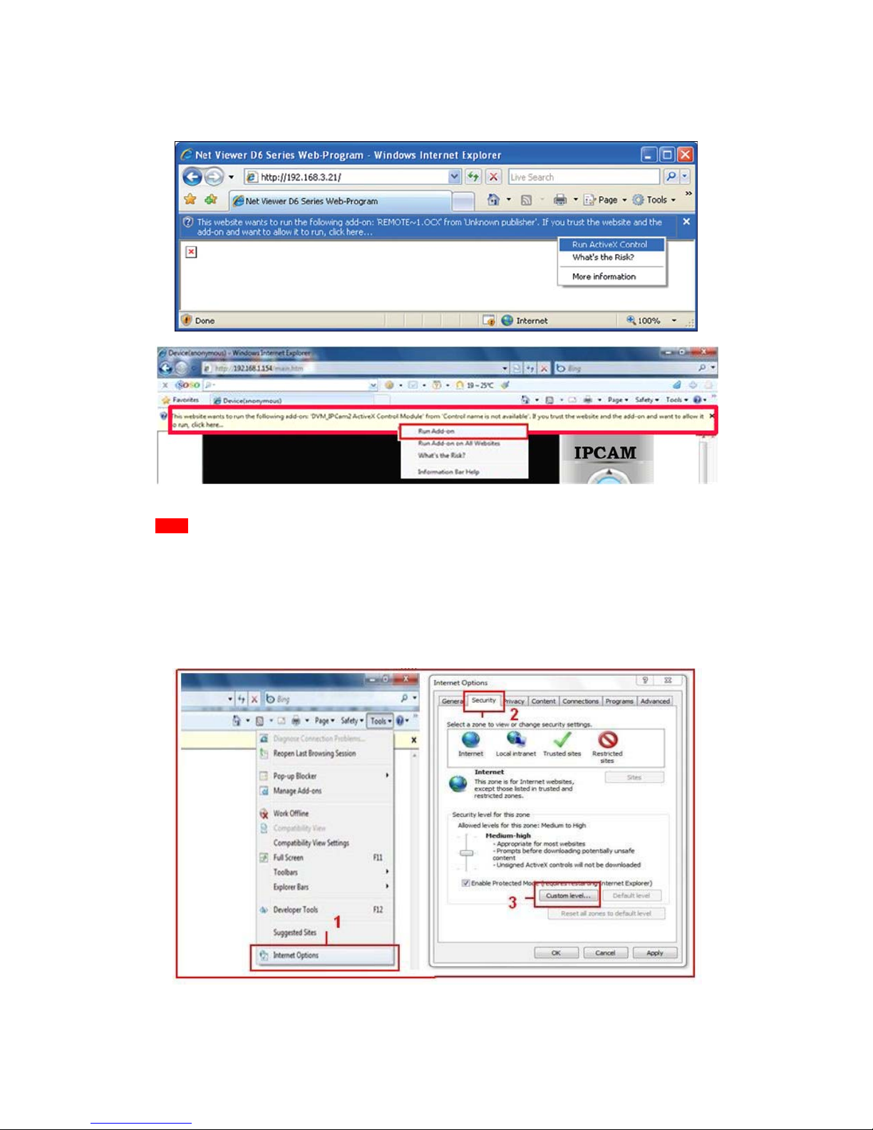
Figure 3.3 Windows XP system
Figure 3.4 Win7 System
Note: If there is still no live video after run ActiveX, please try to enable the Act
i
veX
options of IE security settings, please do the follow steps:
1. Close the firewall of your computer
.
2. Change the ActiveX settings, “IE” browser > “Tool” > “Internet Options” > “Secur
i
ty”>
“Custom Level” > “ActiveX control and Plug-ins”, all the ActiveX options set to be
“Enable”: Espec
iall
y:
Enable: Download unsigned ActiveX contro
l
s
Enable: Initialize and script ActiveX controls not marked as safe
Enable: Run ActiveX controls and p
lu-i
ns
11
Page 13
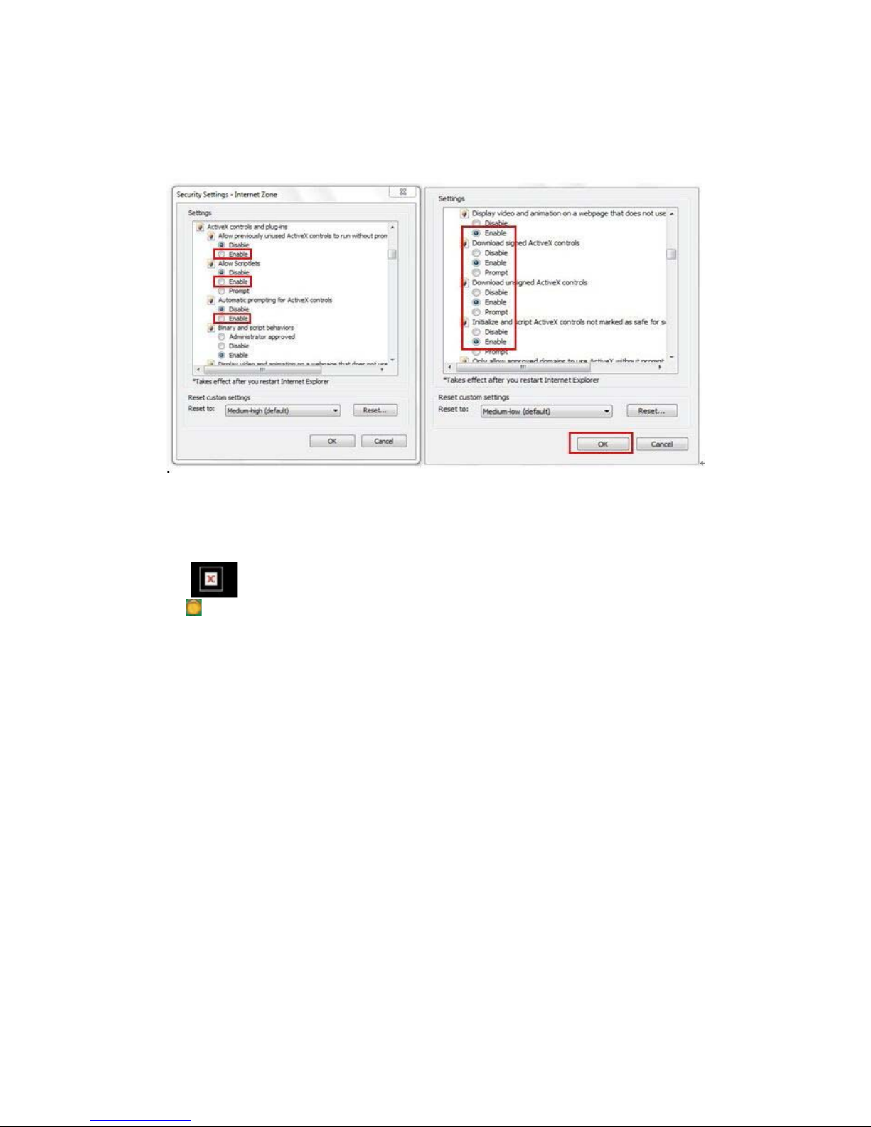
Figure 3
.
5
Figure 3
.
6
In Addition: you can also click “start” menu->“Internet Explorer”, choose “
I
nternet
attributes “ to enter, or via “Control Panel” ->“Internet Explorer”, enter to Security sett
ing.
3. If there is still no image, please close your anti-virus software, and then try step 1 & 2
aga
in.
4. If you allowed the Active X running, But still could not see live video, Only a Red
Cross in the center of the video, And the device status light change to ye
ll
ow
color , not green please change another port number to try, Don’t use port 80, usd other
port such as99, 199 etc
.
12
Page 14

Figure 3
.
7
NOTE: Make sure that the firewall or anti-virus software doesn’t block the software or
ActiveX. If you couldn’t see live video, please close your firewall or anti-virus software
,
and try again
.
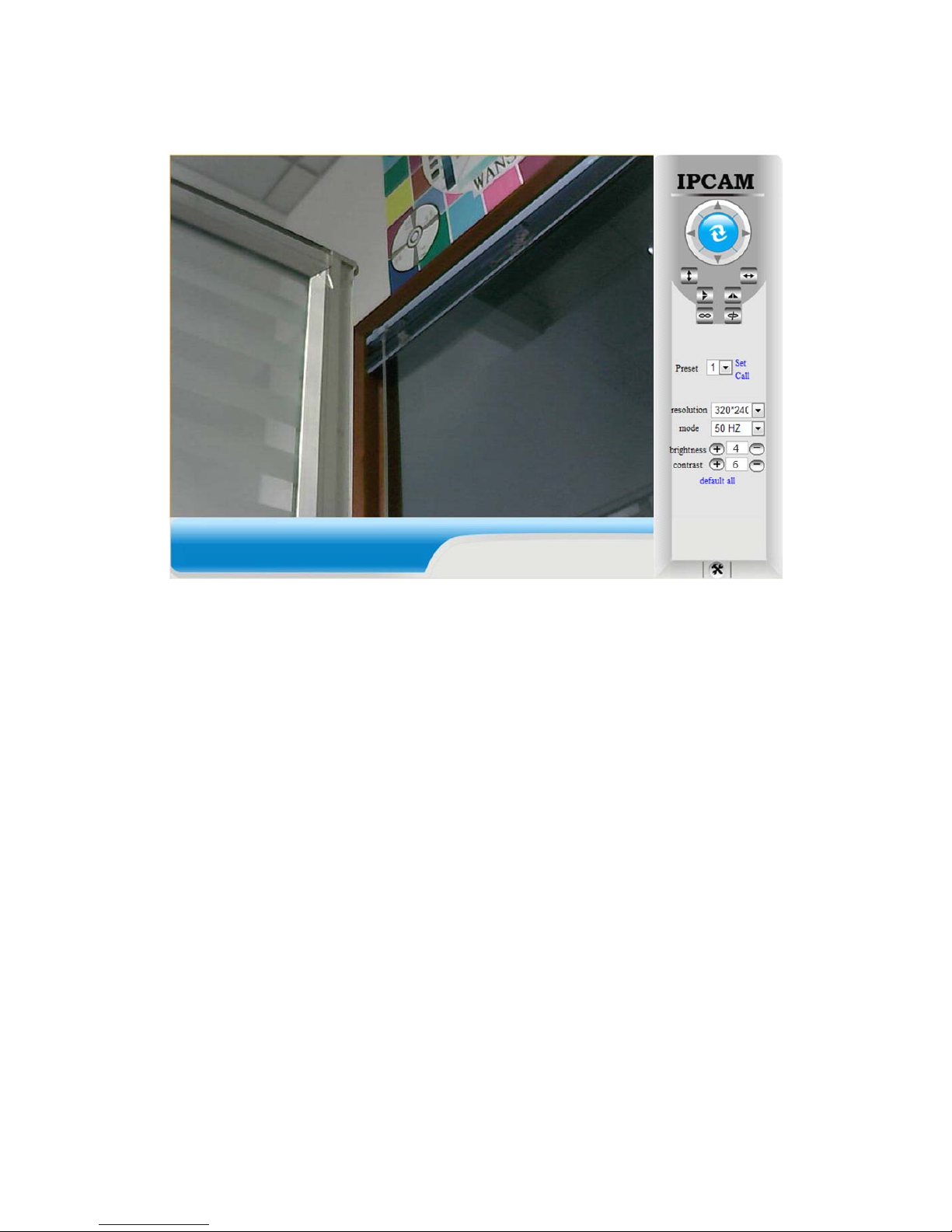
3.3. View via Safari, Firefox, Google
Browser
Choose Server Push Mode (For Safari, Firefox, Google Browser), and sign
i
n
Server Push Mode doesn’t support ActiveX, so some functions are not available, such
As Record, Audio, Talk, Speaker,The speed control bar, Zoom etc.),if you want to use
these functions, please use IE Browser
.
The Control Interface in this mode is as be
ll
ow:
13
Page 15
3.4. Main Menu interface
introduction
Take the “Active Mode(For IE Browser)” For example:
14
Page 16
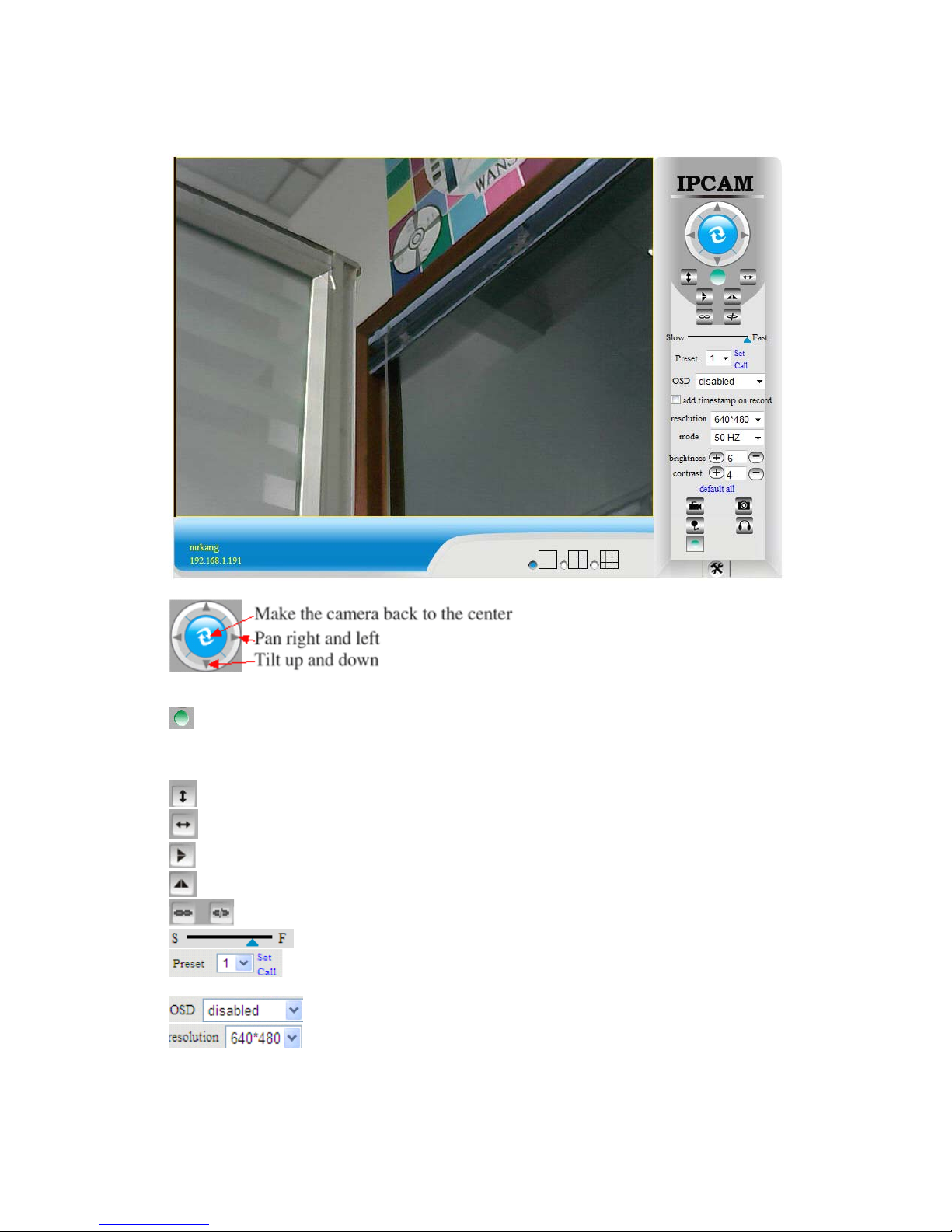
Figure 3
.
8
the cameras have this Pan/Tilt function
.
The Pan/Tilt Feature only work when
This option enables log detection. After the online user clicks this button, a log
i
s
entered into the camera’s Log Data documenting the IP address of users who have
accessed the IP camera. This Option enables alarm detections too
.
This button make the camera Vertical cruise (for the Pan/Tilt Cams)
.
This button make the camera Level cruise (for the Pan/Tilt Cams)
.
This button flips the image vertically
.
This button flips the image hor
i
zontally
.
This button for turn on and turn off the IR LED Light
.
Control the speed of the Pan/tilt. Only work for the Pan/tilt Cams
.
Cams
This button for setting the Preset of the camera. Only work for Pan
/til
t
This setting changes the color of the OSD lettering
.
This setting changes the image resolution
.
15
Page 17

This setting changes the image frequency
.
This setting changes the image brightness
.
This setting changes the image contrast
.
This option resets all main menu options to factory defau
lt.
This option opens the camera’s recording functionality menu
.
This option takes a snapshot of the current screen and saves the snapshot to the
PC’s Hard Dr
ive.
This option enables User-to Camera audio. If the online user
This option enables Camera-to-User audio. If the online user has speakers connected
and configured to their PC, clicking this option will allow them to hear audio from the
location of the camera
.
This button opens the IP camera’s Backend Menu
These options enable single view, quad screen view, or 9 screen view:
This function serves no purpose unless you have more than one camera connected and
configured to your
i
nterface
.
* Please refer to section 8.1.1 Multi-Device Sett
i
ngs*
Open and close the infrared function. IR On
,
IR OFF
3.5. Administer Setting
Instruction
When login as Administrator, you can enter the IP Camera for Administrator
.
Administrator supports all the settings and operations of the camera; you can set and
control it freely There are some special functions only for administrator as be
l
ow:
Alias setting : You can set your favorite device aliases.
Date&Time set : seting the date and
t
ime.
Uer settings : Ca n be set up to 8 us ers. On thi s page you can set up accou nts of t he use r name
,
password, as well as in their packet (administrator, operator, visitor).
�
Visitor : In this mo de, y ou can o nly vi s i
t.
�
Operator :You can set the direction of the lens device, set the video screen’s brightness,
cont ra st and other p arame
ter.
�
Administrator : You can set the device advanced configuration
.
UPnP set :If you want internet ac c ess IPCAM, to ens ure that the sta te is suc c essful UPn P
.
Device Firmware Upgrade: The system firmware update the device firmware and application o
f
Restore factory settings : When there is not a response when the error occurred, you can
restore the factory settings to resolve the device
.
I rebooted the device : rebooted t h e device
.
Back: Return to monitor mode
3.5.1 Multi-Device Settings
�
Add a local area network equipment
In the multi-device configuration page, you can see all the equipment inside the LAN
.
The first device is the default device. You can add more devices listed in the list of
16
Page 18
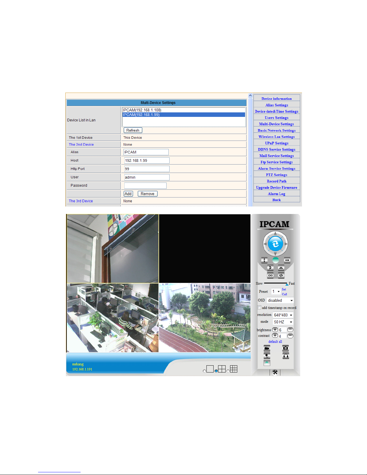
equipment. Embedded applications, up to 4 devices at the same time-line. Click the
“second road equipment” and double-click “Current list of devices in the LAN” in the
device entry name, host address, Http port will automatically be filled, require the user to
fill in the correct account name and password, click “Add.” Repeat this process you can
continue to add devices. Finally do not forget to click on the “Settings” button
.
Figure 3
.
9
3.5.2 Network Settings
Figure 3
.
10
17
Page 19
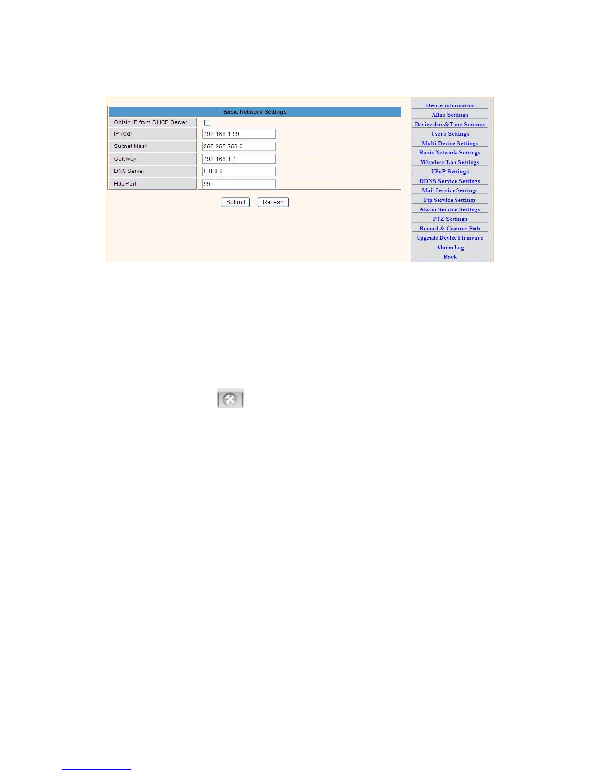
Figure 3
.
11
This sector is for DHCP and IP configuration, port forwarding is needed, If you
choose to set IP address,please fill in the relative IP address, subnet mask, gateway, DNS
server, Http port
;
3.5.3 Wireless Settings
1. Make sure the router is a wireless router
.
2. Make sure the Wi-Fi antenna
i
nstalled
.
3. Make sure whether there is encryption of the WLAN of the router, if there is encrypt
ion,
keep the key
.
4. Login the camera, click
>“Wireless Lan Settings”>”Scan”, please scan 2times,
then you will find the WLAN from the list, choose the one you use
.
5. If there is no encryption, just click “Submit”, if there is encryption, please input the key
,
then click “Submit”
.
6. Wait about 30 seconds, the camera will reboot, then unplug the network cab
le.
18
Page 20
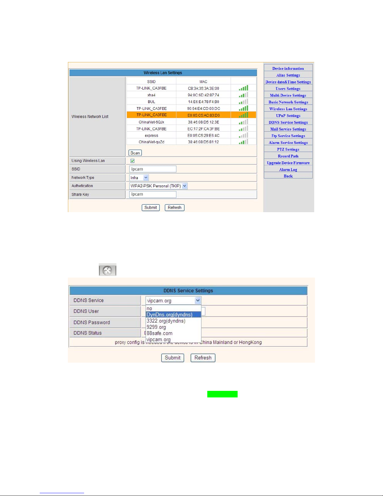
Figure 3
.
12
3.5.4 Dynamic DNS Setting (DDNS)
3.5.4.1 DDNS Setting:
(1): Click > “DDNS Service
Settings”.
Figure 3
.
13
(2): Choose the DDNS, there are 4 kinds of
options:
(1): Manufacturer’ DDNS: We provide a free DDNS: vipcam.org. This domain is provided
by manufacturer
.
Note: 88safe.com is old DDNS provided by manufacturer also. If you want use the manu
f
acturer’s
free DDNS, Please Choose to use vipcam
.
org.
19
Page 21
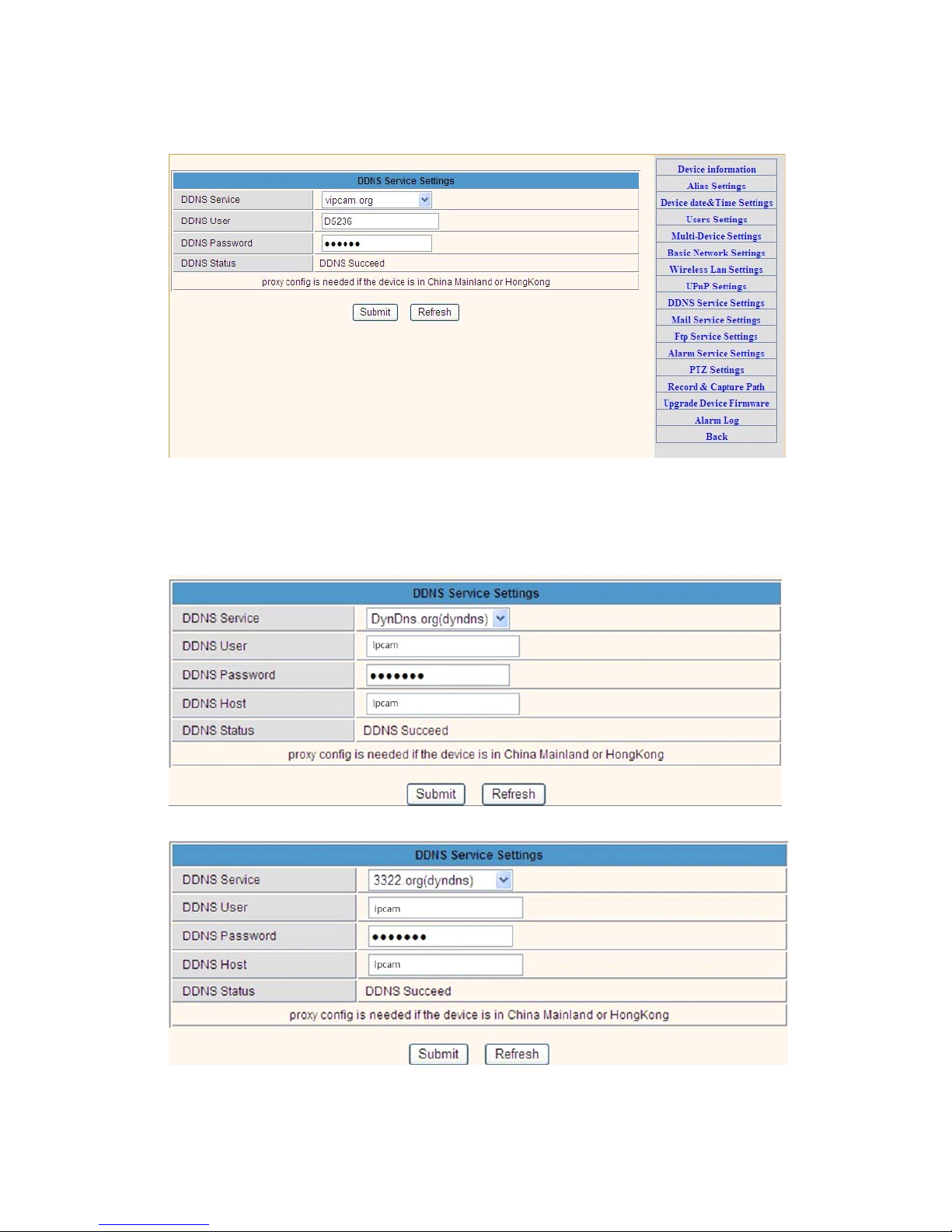
Figure 3
.
14
(2): The Third Party DDNS: This domain is provided by the 3rd party, such as Dyndns,
Oray, 3322
If you use the third party DDNS, please choose the server you need, such as “3322
.
org”
or“dyndns.org” as be
l
ow:
Figure 3
.
15
20
Page 22
Makesu
r
e
the “Subnet Mask” “DNS Server”
isthesam
e
Figure 3
.
16
You have to register an account firstly, keep the user, password, host, then fill in
it.
Note: Only one DDNS can be chosen, for example, if you use manufacturer’s DDNS, the
3rd party one won’t work, if use the 3
rd
party DDNS, the manufacturer’s one won’t work
.
3.5.4.2 Port forwarding settings:
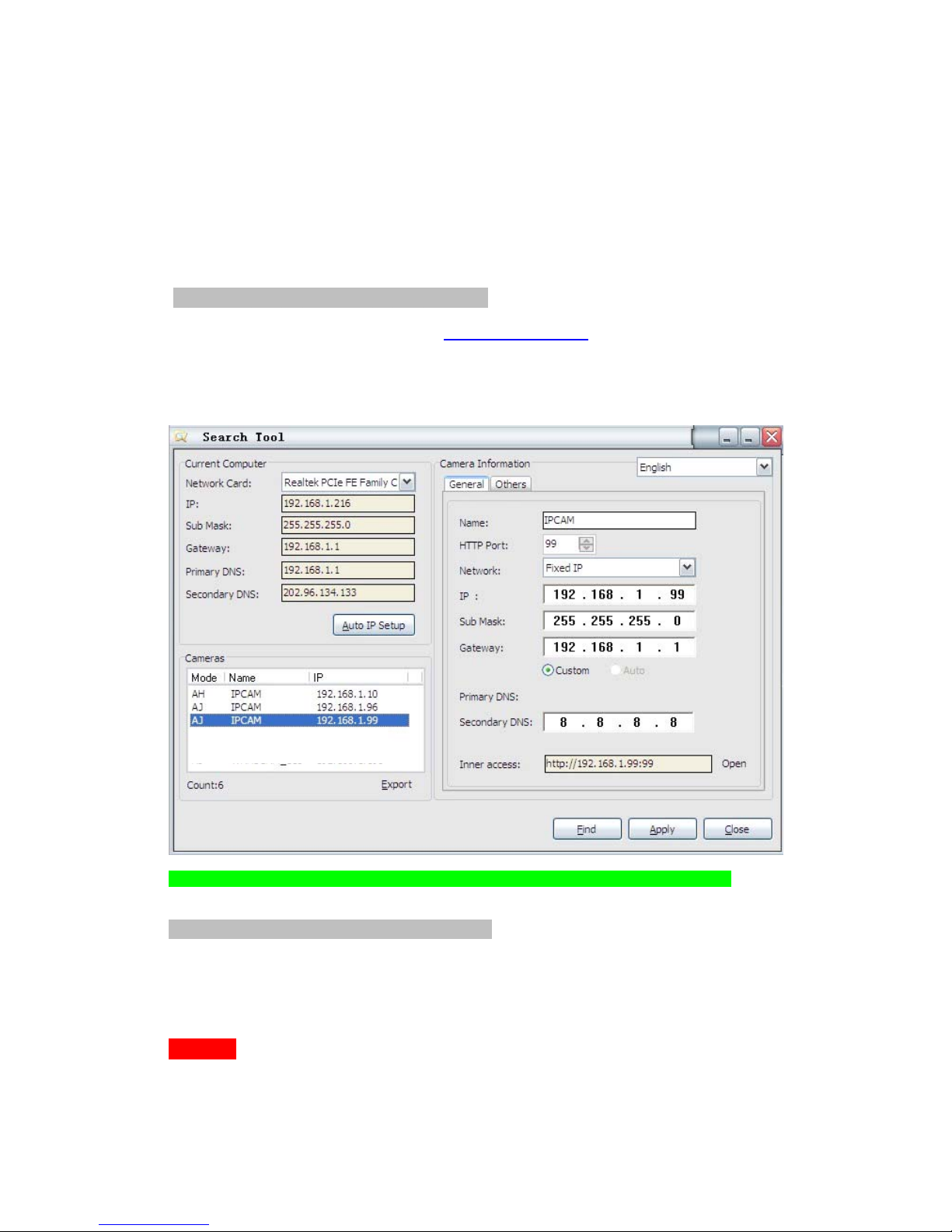
1: Setting the IP address of the
camera
The default IP address of the camera is : Http://192.168.1.99:99 The default IP address of
camera you can change to any other one you like, such as:
Change to: 192.168.1.109:109. or 192.168.1.99:90 etc
.
Click “Apply”>fill in the user name and password of the camera>click “OK” then the
camera will reboot, wait about 30 seconds. You will get your changed IP address
.
Figure 3
.
17
, “Gateway”
,
as your router
.
2: Setting Port Forwarding in the
router.
This is the most important step. Set port forwarding in router refer to the IP of your camera
correctly, then the DDNS will work. Because there are so many kinds of routers from a
ll
over the world, so it’s difficult to show a fix steps, but there are some samples of different
routers’ port forwarding settings as below, just for reference:
TP-LINK:
21
Page 23
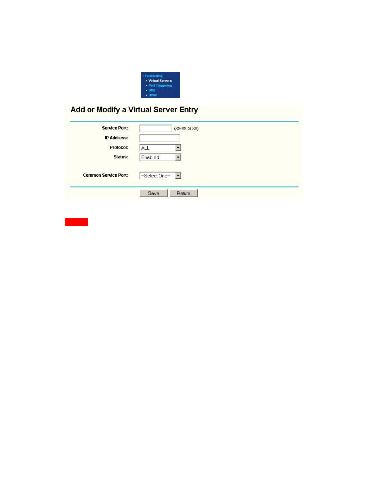
(1) Login the router
.
(2) Choose “Forwarding”, select “Virtual Servers”
(3) Click the Add New button, pop-up be
l
ow:
Fill the service port (except 80), IP address of the camera, then click Save
The port and IP address should be the same as Camera
.
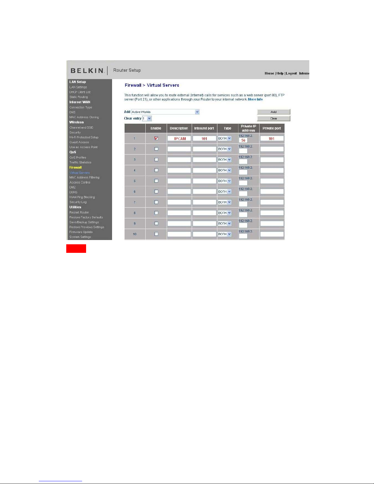
BELKIN:
(1) Login the router
.
(2) Choose “Firewall”, select “Virtual Servers”
(3) Input the port (except 80) and IP address, then click save
.
Note: The port and IP address should be the same as Camera
.
22
Page 24
DLINK:
(1) Login the router
.
Figure 3
.
18
(2) Choose “Advanced”, select “Virtual Servers”
(3) Input the port, IP address, Protocol, then click save
.
Note: The “public port” & “private port” should be the same as camera’s port, choose the
protocol to be “both”
.
23
Page 25
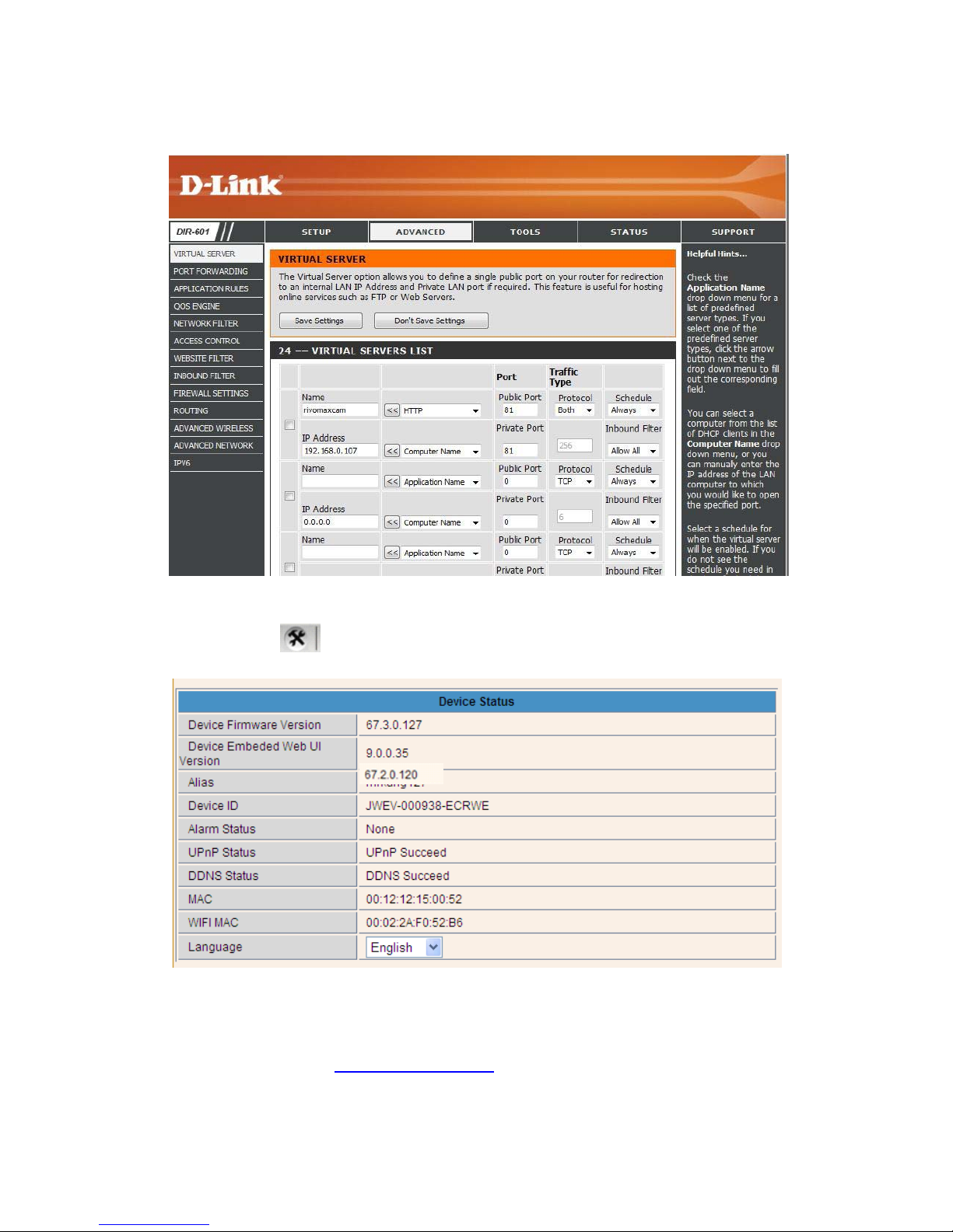
Figure 3
.
29
After all these 4 steps done, then you can use the DDNS freely, check the DDNS status
from the camera as below, and get the link of DDNS for internet v
iew.
Step: “Login”>”
”>”Device Info”:
Figure 3
.
20
3.5.5.3 DDNS Register
For example, you can go to Dyndns website to register a free account
.
http://www.dyndns.org / http://www.dyndns.com
.
24
Page 26
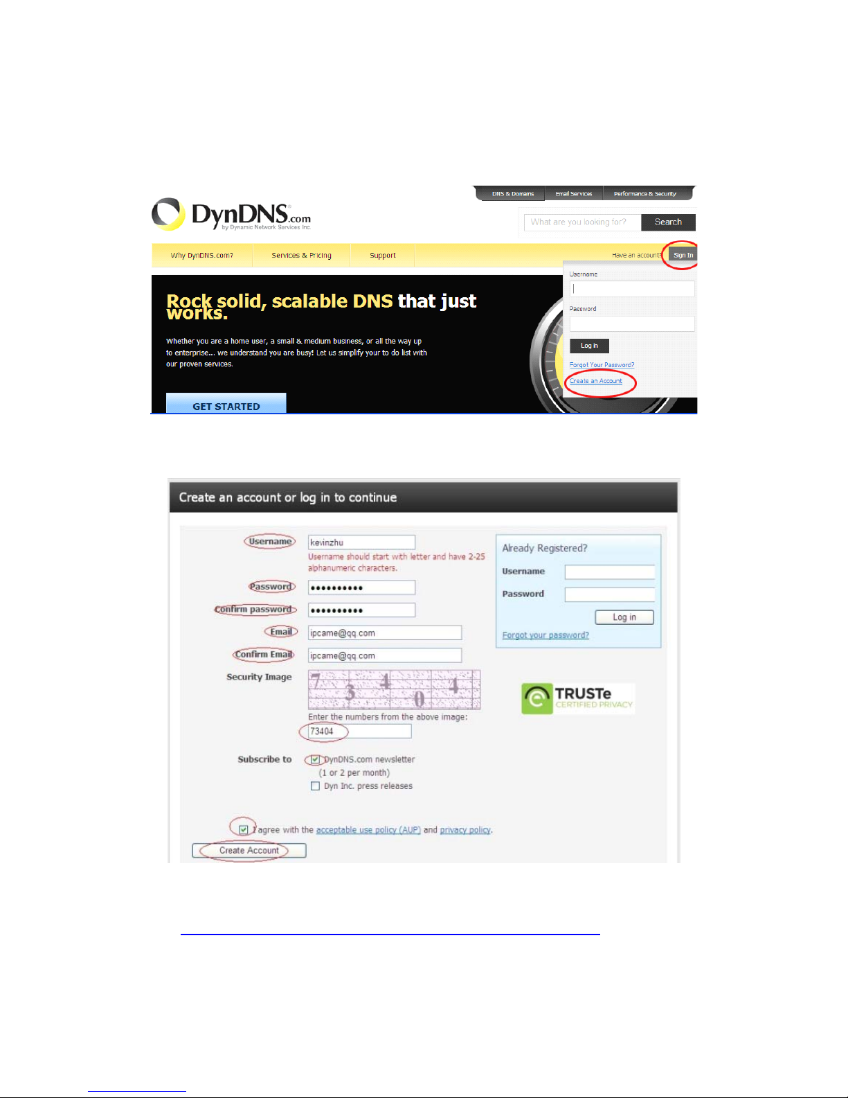
Step1: enter http://www.dyndns.com/ and Create Account
Figure 3
.
21
Step2: Set the username and password as be
l
ow:
Figure 3
.
22
Step3: After a minute, you will receive a E-mail from DynDNS Support and it will give you a
confirmation address
(e.g. https:
//
www.dyndns.com/confirm/create/ONMzltcCBk6mcHJI5MhVD0g)
25
Page 27
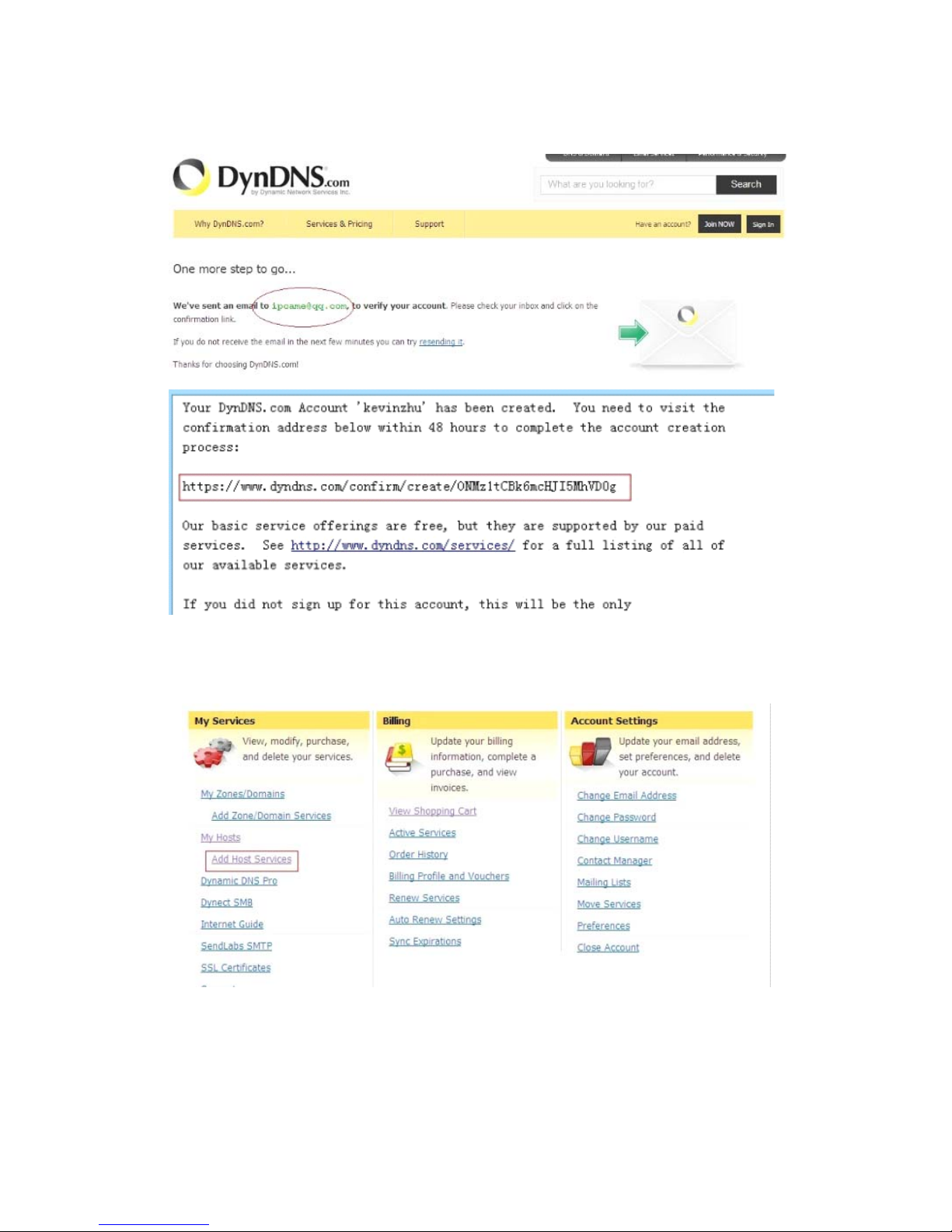
Figure 3
.
23
Figure 3
.
24
Step4: When the Account Confirmed, login and start using your account. Choose Add
Host Services(Figure 3.25) and enter Add New Hostname (Figure 3
.
26)page
.
Figure 3
.
25
26
Page 28
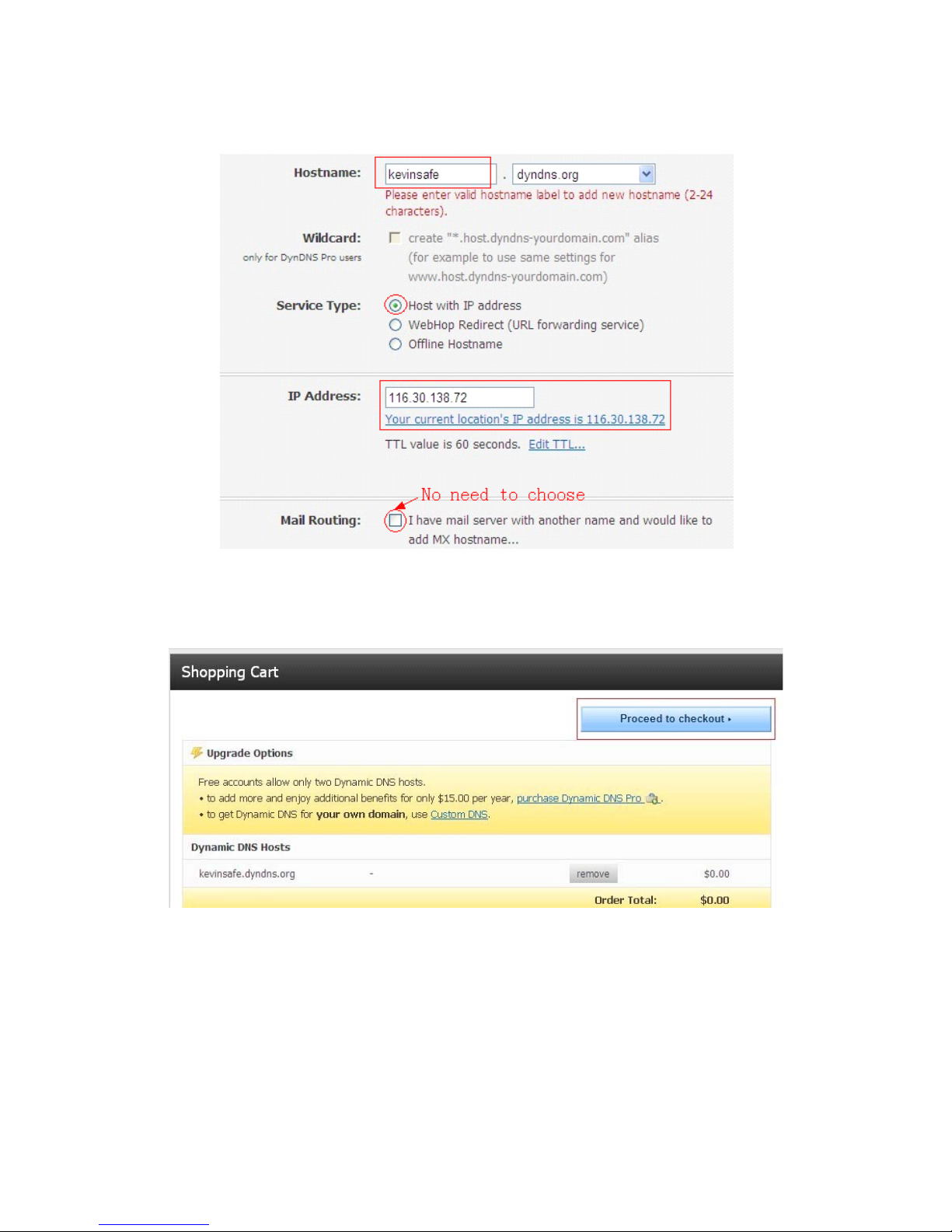
Figure 3
.
26
Step5: On the Add New Hostname page
.
1) input your Hostname
.
2) choose Host with IP address
3) click Use auto detected IP address xxx.xx.xx.xxx. Then click Create Host
.
4) after you have added a New Hostname , you need “Proceed to checkout”
Figure 3.27
27
Page 29
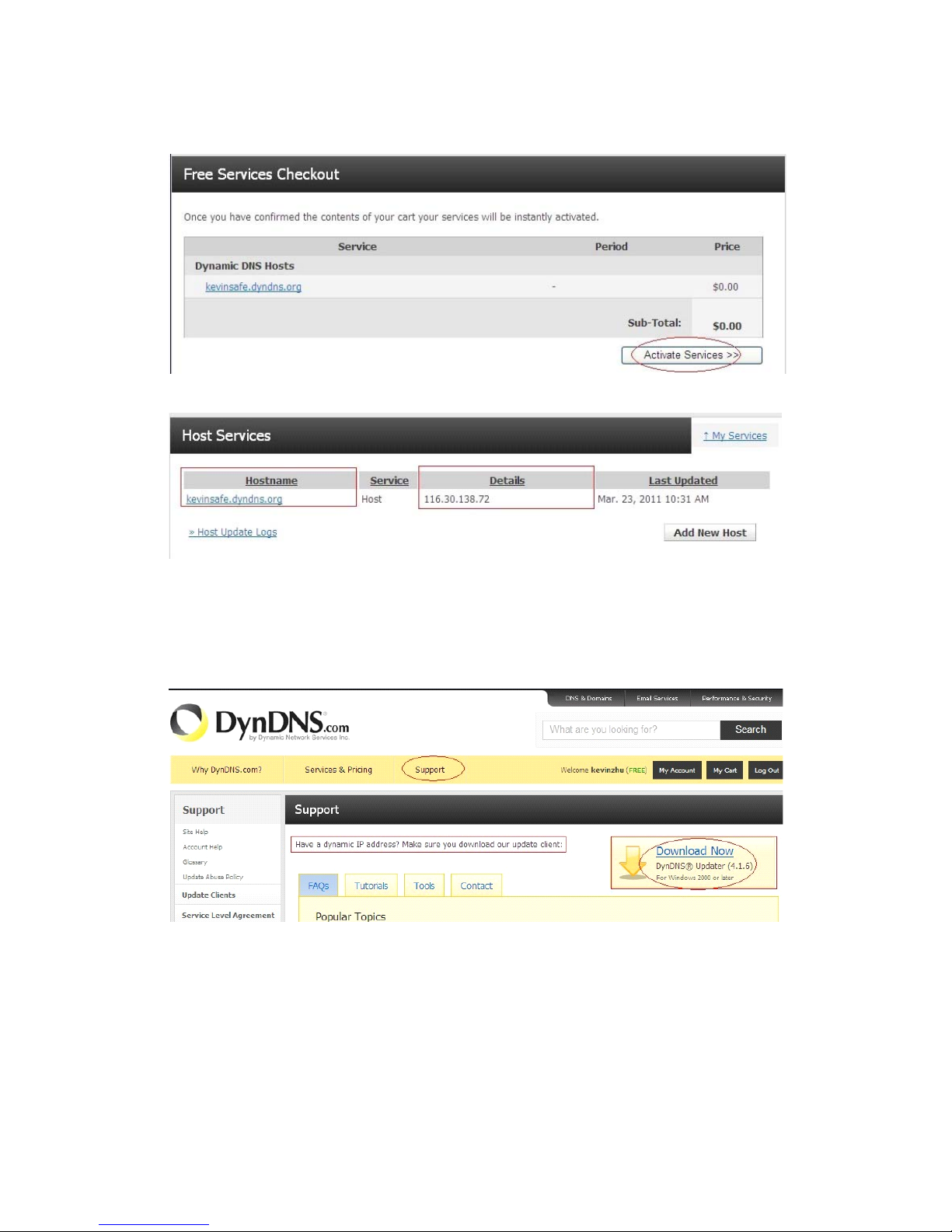
Figure 3
.
28
Figure 3
.
29
Step6: Now you obtained a Dynamic Domain Name(Figure3.30),and can use it in the DDNS
Service Settings(details: 3
.5.
5)
Not
i
ce:
If you have a dynamic IP address, Make sure you have download the DynDNS’s “Update
Client”. And installed it succeed in your computer
.
Figure 3.30
28
Page 30
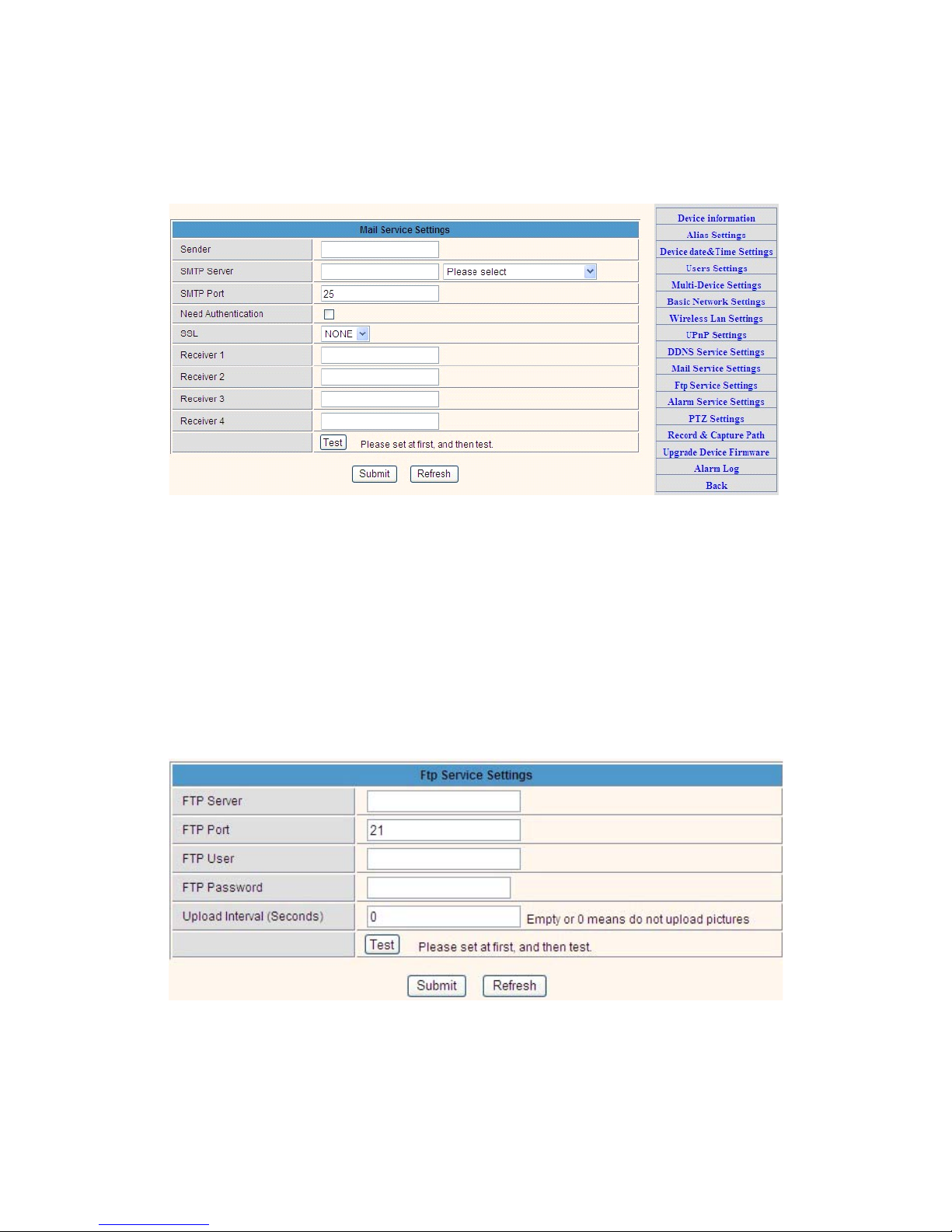
3.5.6 E-mail and FTP service Settings
Figure 3
.
31
The above setting is a preparation for the alarm function, the sender should be
entered the sender’s email address,recipient 1、2、3、4 is filled with recipient E-ma
il
address;SMTP server should be filled with the sender email SMTP server,e.g. the
sender email address is [email protected],and enter mail.163.com. Generally SMTP port
is 25,do no need to change;when needs to check, just tick it, and enter SMTP user
and SMTP password,both of them are provided by Email provider,and test accord
i
ng
to reference;when needs to send, please tick Email notification Internet IP address;
The e-mail server and other information can be obtained from the mail serv
i
ce
provider the email notification is image captured when alarming if no ema
il
notification is needed when alarming, and then no need to enter
.
Set up FTP service, you can fill in parameters like follow
i
ng:
Figure 3
.
32
The above setting is equally similar to Mail Server Settings,when alarming is
triggered it also sends image,please enter FTP server,FTP port,FTP user
,
FTP
29
Page 31
password, FTP upload directory,FTP mode,FTP mode has two options: PORT and
POSV. If needs a quick upload image, then select it, edit upload image
i
nterval(second)
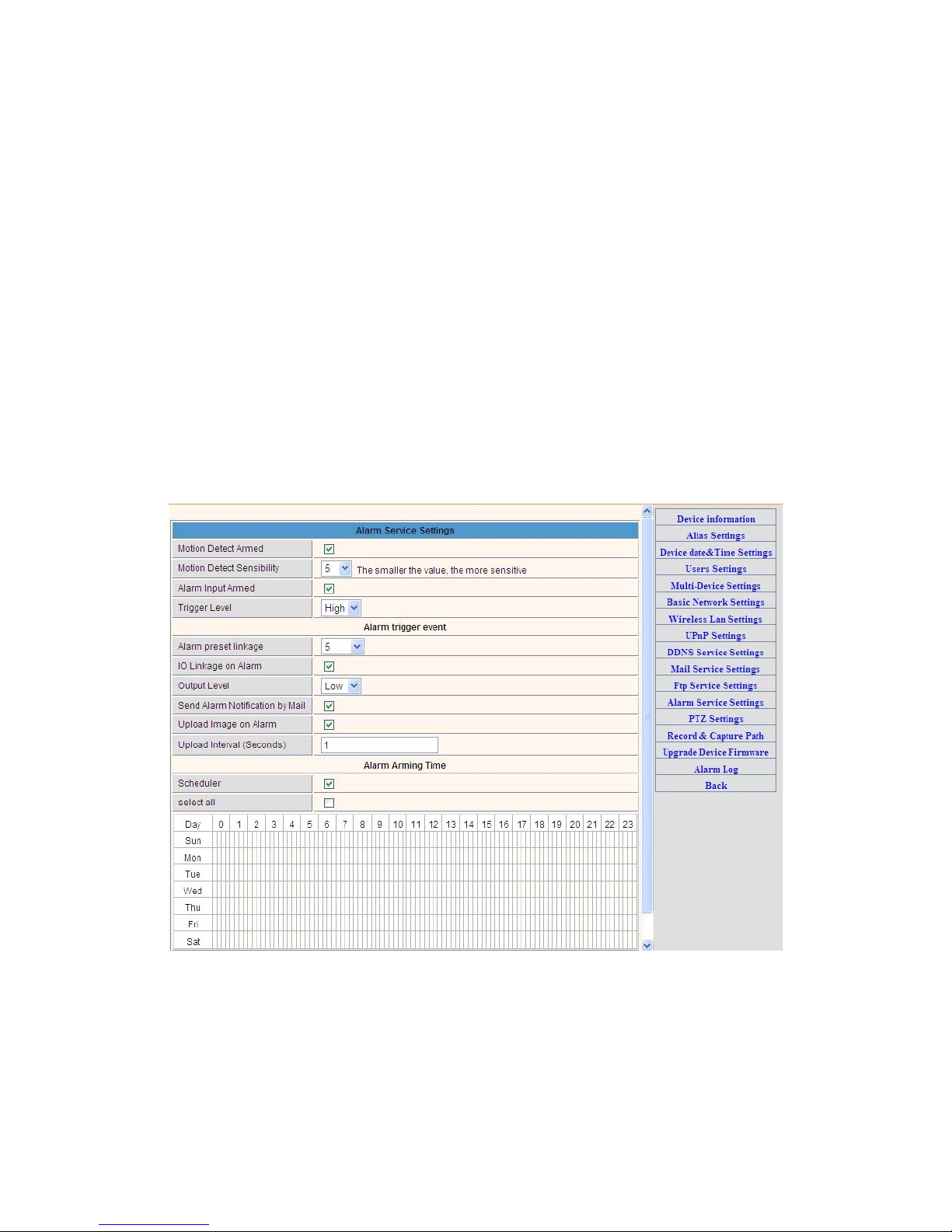
3.5.7. Alarm Service Settings
As shown below, there are two modes of alarm trigger, first one is motion detect
ion,
please refer to below interface,the sensitivity of motion detection can be ad
j
usted
according to the users′ requirement, the higher the number is, the lower sens
itivi
ty
is; Another mode is input alarm, when connected, it triggers alarm through a
l
arm
input signal which connects to linkage alarm GP
I
O;
When triggered, there are 3 alarm modes:one is IO alarm linkage, camera connects
with linkage alarm box through GPIO, sound the siren ;the second is ema
il
notification, send email with images captured;the last is upload pictures alarm,as the
way mentioned before FTP upload pictures alarm, Upload pictures
i
nterval(second)
keeps consiste nt with the mentioned upload pictures interval of Ftp service sett
i
ngs
.
The schedule refers to arming time,as the selected time interval: 0:00 minute per
week to 0:45 minutes and Monday 1:00 hour and 2:00 hour
F
i
gure3.33
30
Page 32
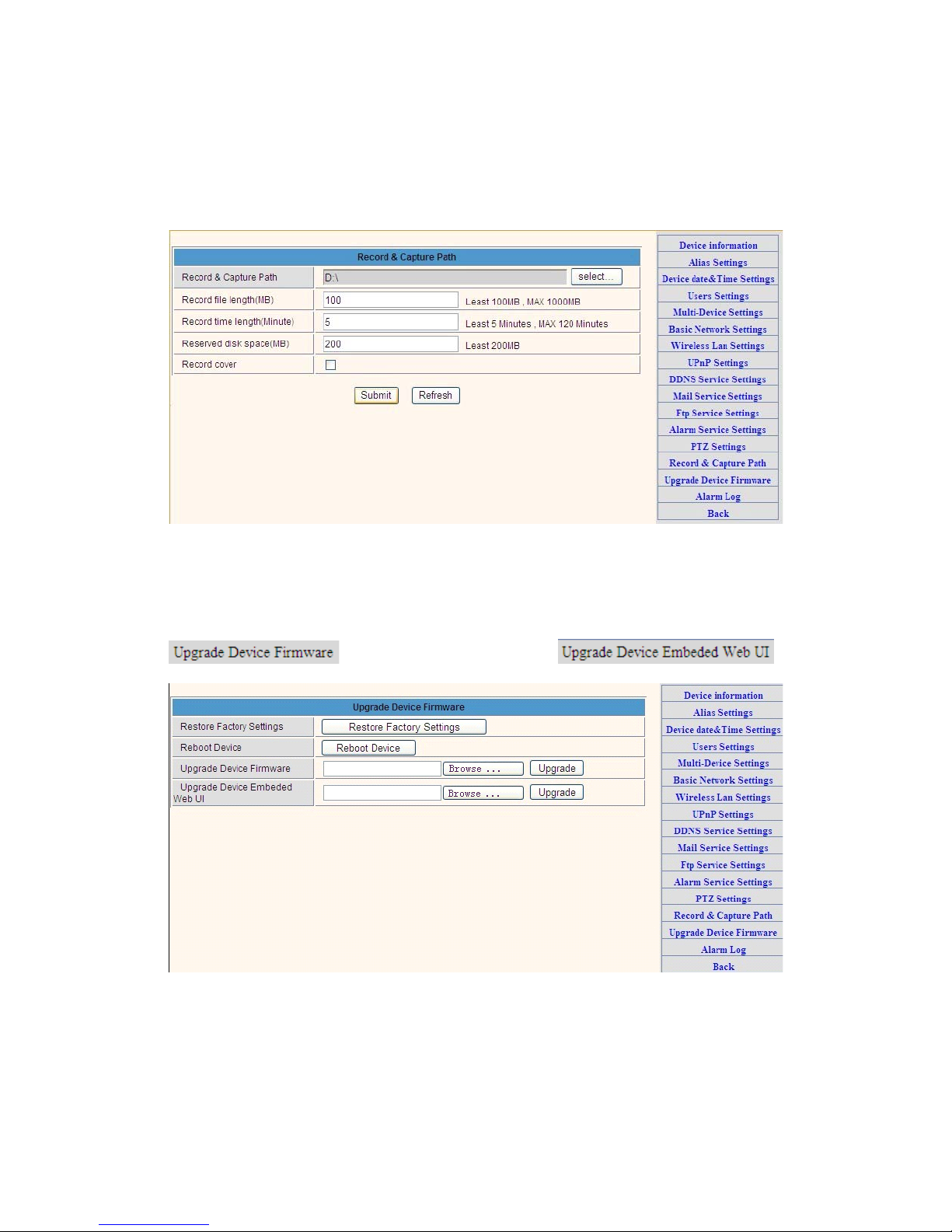
3.5.8 Record&Capture Path
This sector is for Record&Capture Path in your computer.It include: Record&Capture
Path, Record file length(MB), Record time length(Minute), Reserved disk space(MB)
,
Record cover
.
Figure 3
.
34
3.5.9 Reset/Firm Ware Upgrade
This sector is for camera firmware upgrade, it includes device system f
i
rmware
and device application firmware
.
Be cautious to apply for
i
t!
Figure 3.35
31
Page 33
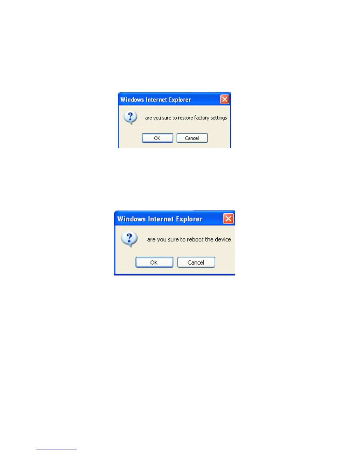
3.5.9.1 Restore Factory Settings
When users forget password, we can restore ex-factory settings, when click, a p
i
cture
will pop up, Click ok, and wait for 1 minute and you can use it normally. User sett
i
ng
feature restores
3.5.9.2 Reboot Equipment
Figure 3
.
35
Click restart, it appears the above picture, click ok, wait for 1 minute and you can use
it norma
ll
y
Figure 3
.
36
4 Warranty
Under normal use condition, products resulting from its own failures in the
warranty period will be free maintenance. Warranty Terms as fo
llowi
ng:
a) Charge-free maintenance of the product is one year. We can repair it for free
during the guarantee period (Damages not caused by misuse or vanda
li
sm)
.
Repair over guarantee period, we will charge maintenance fee
.
b) During guarantee period, breakdown caused by misuse or other reasons out of
32
Page 34

range of warranty. You could ask repair depend on the card. We only charge for
changed components, the maintenance charge is free
.
c) When the products need maintenance, hand up the card with products to the
manufacture or local d
i
stributor
.
d) Take apart item crust, tear up the sealing label privately, this is out of
warranty range
.
e) We do not accept the damaged item due to modification or add other
funct
i
ons
.
The Following Circumstances will not be free warranty
a) Period check, maintenance or change components due to normal attr
ition.
b) The damages due to crash, extrusion, artificial flooding, moisture or other
personal reasons
.
c) The damages due to floods, fire, lightning strike and other natural ca
lamiti
es
or force majeure incidents factors
d) Repaired item by non-authorized repair centers
.
All above terms, if changed, regarded to relevant regu
lati
ons
.
THA T’S ALL, THANK YOU!
33
 Loading...