

Service Manual
Rev.1.0 January 2013
PW-C25 & PW-C25P
Models
1509P-M 230V 50Hz
I1509P-M 230V 50Hz
1813P-T 400V 50Hz
I1813P-T 400V 50Hz
I1310P4-M 230V 50Hz
Pag. 2
PW
-
C25 / PW
-
C25P
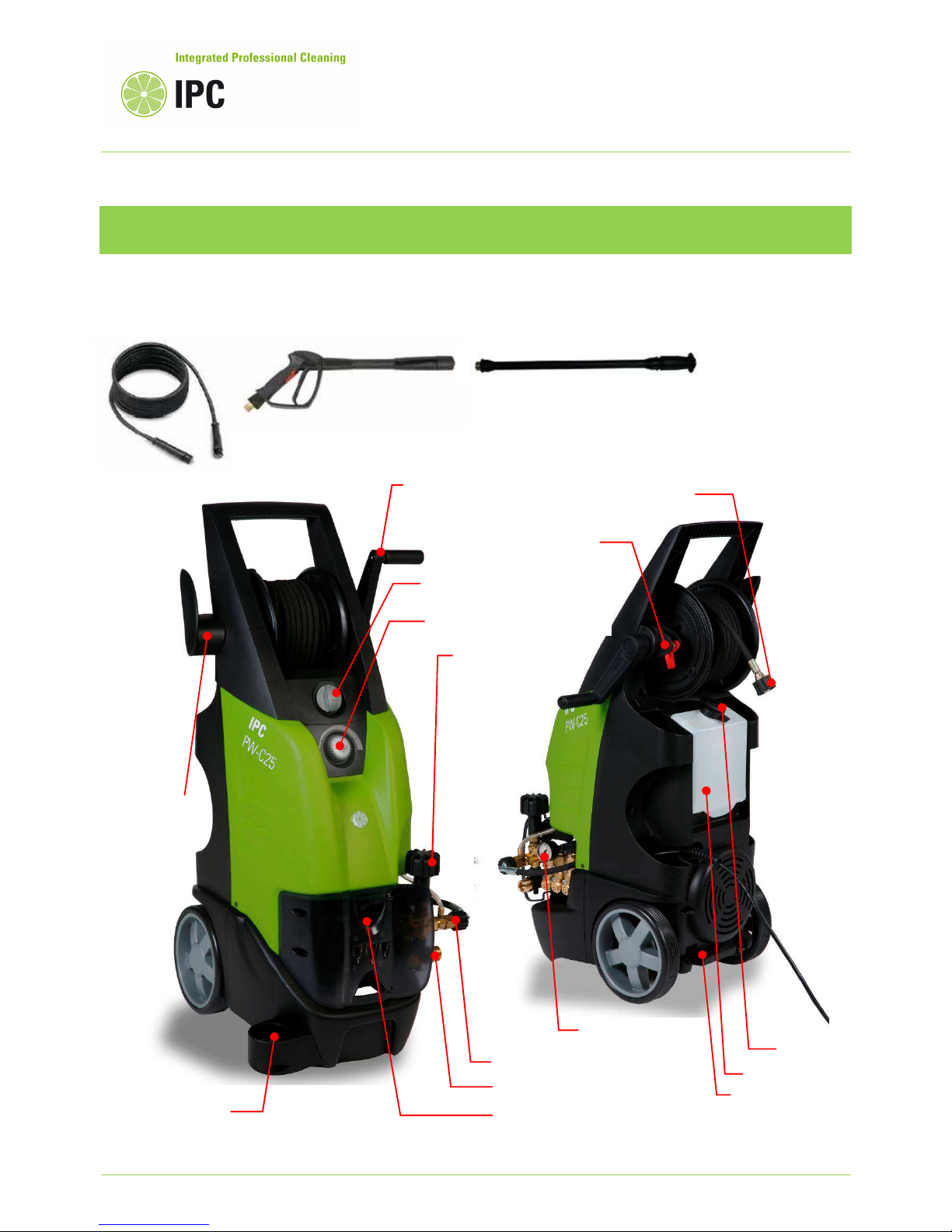
outer layout
High pressure hose – spray gun – lance
Hose reel handle
Main switch 0-I
Chemical tap and regulator
Lance holder
Water inlet fitting
Water outlet fitting
Pressure adjust
Pump oil window
Pressure gauge
Hose reel rotation lock
Chemical tank
Lance holder
High pressure outlet
Foot lever
Refill cap
Pag. 3
PW
-
C25 / PW
-
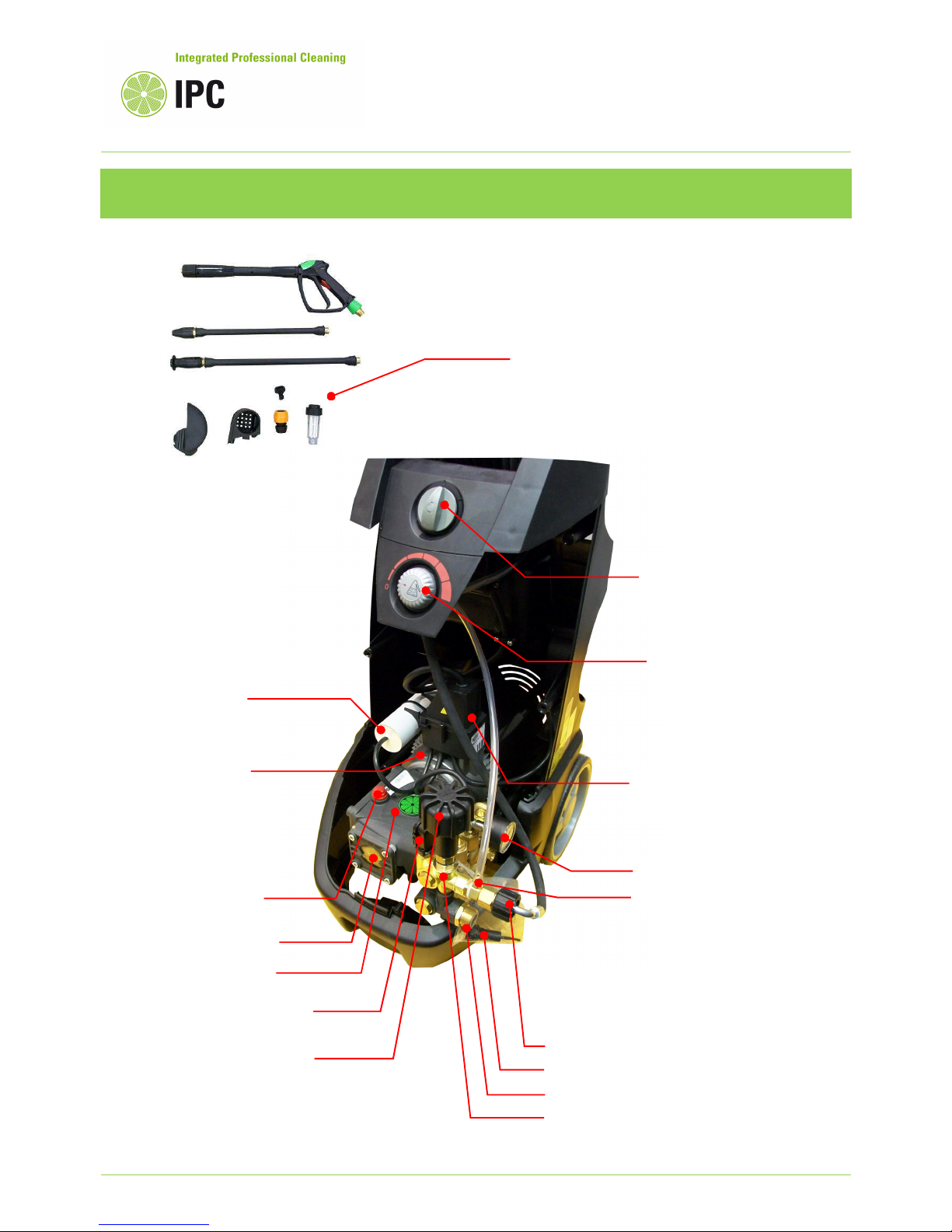
C25P inner
layout
Water outlet fitting
Water inlet fitting
Pressure gauge
Oil cap with air breath
By-pass valve
Total stop micro-switch
Pressure adjusting knob
Oil cap for handling and
transportation
High pressure pump
Oil level window
Electric motor starting
capacitor
Electric motor
Electric enclosure
Chemical injector
Chemical tap and dose
Main switch
Standard accessories
set, that includes the
inlet water filter and
“garden” quick inlet
fitting.
Pag. 4
PW-C25 / PW-C25P
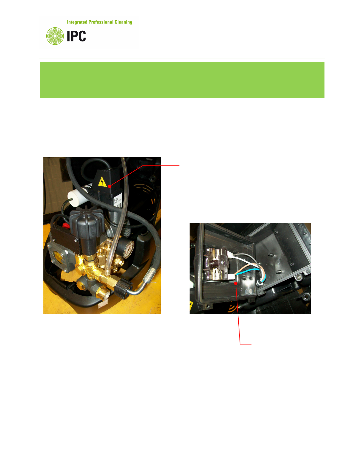
electric box components
layout
Electric box for wiring
the electric motor, the
starting capacitor, the
total stop switch and the
power cord.
Electric box for on – off
main switch

Pag. 5
Service Manual
INDEX
Topics
1. The machine doesn’t starts Page
1a No electrical connection 7
1b No electrical supply to the electric motor or
motor thermal sensor overload intervened or burnt fuses 7
1c The micro-switch of bypass valve not working
(only for machine with total stop system)
12
1d Contactor not working (on versions three phase or P4) 13
2. No water jet at the lance nozzle Page
2a Bad or missing water feeding connection 14
2b Inlet water filter clogged 14
2c Air intake from the water feeding circuit 15
2d Pump head valves ceased 15
2e High pressure nozzle clogged 16
3. No pressure to the lance Page
3a Defective water feeding connection 17
3b Inlet water filter clogged 17
3c Air intake from the water feeding circuit 18
3d Pump head valves ceased or worn 18
3e Lance nozzle set in low pressure mode (detergent mode) 19
3f High pressure nozzle worn or deformed 19
3g Pressure adjusting valve setting at minimum position 20
3h Seat of pressure adjusting valve damaged 20
3i Pump gaskets worn or water leaks from the pump head 23
Ip Cleaning S.p.A.
Viale Treviso, 63 – 30026 Summaga di Portogruaro – VENICE – ITALY
Tel. +39 0421 205511 (r.a.) – Fax +39 0421 204227
Internet address: www.ipcportotecnica.com
e-mail address: infoipcportotecnica@ipcleaning.com

Pag. 6
4. Poor detergent delivery Page
4a Detergent tap closed/off or clogged 24
4b Empty detergent tank or nozzle not set in detergent mode 25
4c The check valve of the detergent circuit is sticky or clogged 25
4d High pressure outlet pipes clogged or too much extended (over 20 m).
Wear and tear of the detergent nozzle 26
4e Pressure regulator is not set at maximum position 26
5. Oil and water emulsion phenomena to the high pressure pump oil Page
5a Extremely high environment humidity percentage 27
5b High pressure pump gaskets worn 28
5c High pressure pump pistons damaged 28
6. The total stop system doesn’t intervenes
(only for machines having this option) Page
6a Water leaks from the high pressure outlet circuit 29
6b Micro-switch of the bypass valve, or contactor, not functioning 29
Pag. 7
1. The machine doesn’t starts
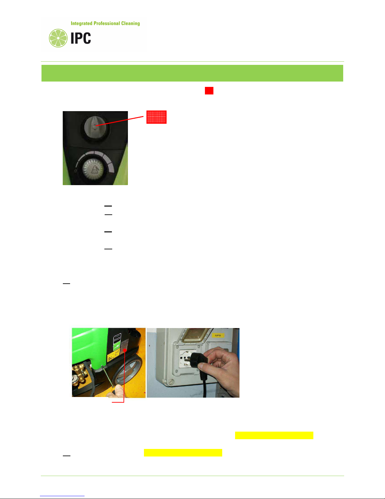
1) TROUBLE: Rotating the main switch “0 – I” (A) the high pressure cleaner doesn’t starts or
starts, but suddenly stops after a while.
CAUSES: 1a No electrical connection
1b No electrical supply to the electric motor or motor thermal sensor overload
intervened or burnt fuses
1c The micro-switch of bypass valve not working
(only for machine with total stop system)
1d Contactor not working (on versions three phase or P4)
REMEDIES:
1a Check the power supply voltage using a “multimeter”.
The machine power supply characteristics are indicated on the machine data plate placed on the
rear side of its chassis.
For single-phase models, the allowed voltage tolerance is +/- 5%.
For three-phase models, the allowed voltage tolerance is +/- 10%.
If the voltage is over or lower than the above mentioned tolerance, the machine electric
components may become damaged.
Pay maximum attention while checking electric component: danger of electric shocks.
1b Pay maximum attention: danger of electric shocks.
Disconnect the machine from the power supply before opening the electric enclosures, hence:
(A)
Machine data plate
Pag. 8
- check using a multimeter, the conductivity of the main switch contacts, rotate the switch knob to
position “I” and in case of problems, replace the switch with a new component.
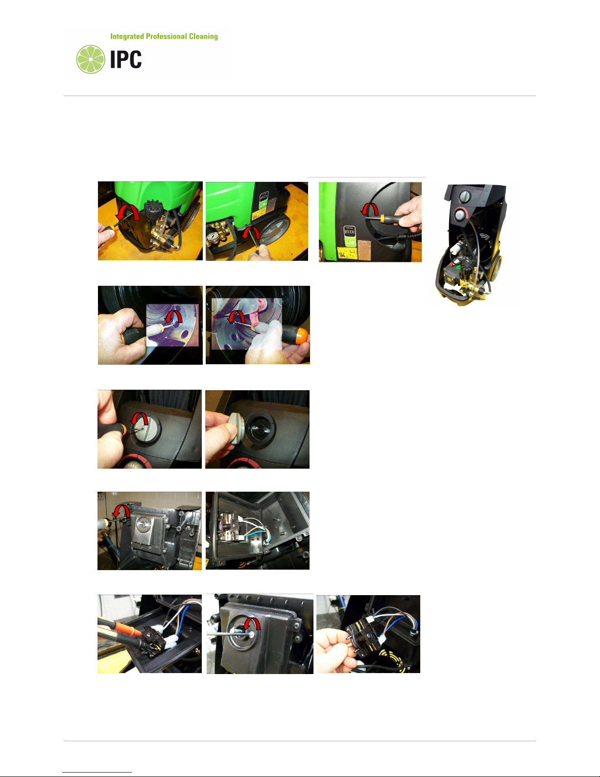
To open the electric enclosures, proceed as following described:
Opening:
3. Remove the main switch knob
1. Remove the machine cover
5. Check the main switch contacts continuity using a
multimeter, if damaged replace it.
2. Remove the handle cover
4. O
pen the electric box cover
Pag. 9
- If the thermal sensor of the electric motor is intervened, the electric motor is disconnected and
the machine cannot work.
The thermal sensor, intervenes when the motor winding temperature is over 155°C and in order
to cool it down and allows its automatic reset, are required some minutes with the electric motor
off.
The thermal sensor is built-in into the motor winding of single phase models, while is wired into
the electric box for three-phase models or for P4 models.
The thermal sensor is a protection against overload and needed to prevent burning of the motor
windings, but has a limited life in term of number of interventions and if the machine has been
used continually under overloaded, the thermal sensor can become damaged and loose the
capacity to self reset, hence not allowing the motor to restart when decreases the winding
temperature.
In order to restore a damaged thermal sensor, is needed to replace the complete electric motor
stator.
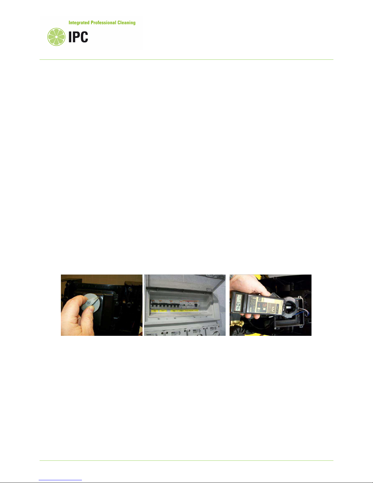
- If the fuses of the socket or to the plug are burnt, the machine is not power supplied; replace the
fuses and check if their amperage is enough for the machine Amperage characteristics that are
readable on its data plate.
Take into consideration that a low voltage supply can cause difficulties to the motor starting and
as a consequence can makes that fuses burn.
We recommend to check the machine amperage using a clamp meter in order to be sure that the
machine working at the maximum pressure is not absorbing more Ampere than what indicated on
its data plate.
Measured
Amperage
should be less or
equal than Amperage wrote to the machine
data plate.
Check the Amperage with a A clamp meter
after switching on the machine and checking
that the machine is correctly power supplied
by the fuses.

Pag. 10
Electric diagrams
Single phase by-pass Single phase total stop

Pag. 11
On which :
•
IQ = Main switch of the power supply socket
•
F = Fuses of the power supply socket
•
CV1 = Machine power cord
•
IG = Machine main switch
•
M = Electric motor
•
TP = Thermal overload protection (clicson)
•
C = Electric motor starting capacitor
•
K = Contactor
•
A1 – A2 = Contactor coil
Three phase by-pass Three phase total stop

Pag. 12
1c Total stop versions have a micro-switch “S” that controls the contactor “C” on three phase
models and that controls directly the electric motor on single phase models, hence makes the
pump and motor unit to start and to stop accordingly with the position of the spray gun trigger:
- When the spray gun trigger is activated, and the lance is ready to spray water, the micro-
switch “S” is closed (on), the contactor (if present) is activated (on) and the electric motor is
power supplied.
- When the spray gun trigger is released, the lance stops to spray water, the micro-switch “S” is
open (off), the contactor (if present) is open (off) and accordingly the electric motor is not
power supplied and stops in “total stop mode”.
In case that the micro-switch “S” is defective or the piston that activate the micro-switch is not
sliding inside of the by-pass valve, the machine cannot start.
Check the pressure-switch continuity using a multimeter as following described:
Dismount the and open the micro
-
switch enclosure.
Check the pressure
-
switch switching capacity and continuity by using a multimeter.
Unscrew the piston that
activates the micro-switch
Slide out the piston and its
spring, check if parts
are wear and tear and if necessary replace them.
Lubricate with grease at the reassembly.

Pag. 13
1d The contactor “C” is installed only on three phase or P4 models and power supplies the
electric motor accordingly to the status of the micro-switch “S” and main switch “IG” for machine
total stop version and only the status of main switch “IG” for machines by pass version.
Check using a multimeter if the contactor coil “A1-A2” is power supplied and check if the power
contact of contactor have continuity when are closed.
We recommend to check the proper functioning of safety electric
components, at least once a year.

Pag. 14
2. No water jet at the lance nozzle
2) TROUBLE: No water jet sprayed from the lance nozzle.
CAUSES: 2a Bad or missing water feeding connection
2b Inlet water filter clogged
2c Air intake from the water feeding circuit
2d Pump head valves ceased
2e High pressure nozzle clogged
REMEDIES:
2a Check the supply water flow (l/min), in order to ensure that supply water available is
sufficiently high compared with the machine characteristics.
The supply water flow (l/min) must exceed at least 10%, than the water flow characteristics
declared in the machine data plate.
Check the fittings to the water inlet circuit and particularly ensure they are not damaged or not
properly sealed, causing flow obstruction or air intakes.
2b Check and clean the water supply inlet filters and if necessary, replace them.
We recommend to check the water filter every 50 hours (or every week)
Check and clean the filter place the high pressure pump inlet or at the water tap outlet.

Pag. 15
2c Check the water circuit that connects the water tap to the high pressure pump inlet,
particularly check that fittings are properly tightened and not leaking water.
This model has not capacity to intake water from a tank placed lower than the machine inlet
fitting, hence this machine can only to intake the water from a tank placed above than the
machine water inlet fitting.
In the above functioning circumstance is important to check that the inlet circuit is perfectly
sealed to avoid air intakes.
2d Check the inlet and outlet valves placed into the pump head; if the valves are sticky, unstick
the valve from its seat manually pressing gently the valve disk until released.
If the valves are dirty, disassemble them and clean.
We recommend the replacement of inlet and outlet valves every 500 hours or one a year.
Strip out the valves, use a screw M4 to link and pull out the valve
Unscrew the inlet valve caps
Remove the 6 valve from the pump
head and replace them if wear and
tear
Unstick the valve from its seat
pressing gently with a pin.
Reassemble the caps using sealing
glue type Loctite 542.

Pag. 16
2e Clean the high pressure nozzle and if necessary, replace it with a new genuine part.
Check the spare part book in order to identify the nozzle size.
The nozzles are colored with different colors to make possible the identification of their size, the
part number description include the color information (see the part manual for PW-C25).
We recommend the high pressure nozzle replacement every 200 hours or any time the machine
working pressure become 20% lower than rated pressure.
Unscrew the nozzle using an Allen key
size 2 mm.
Clean the nozzle orifice with
the help of a steel wire
diameter ≤ 1 mm.
Pag. 17
3. No pressure to the lance
3) TROUBLE: The high pressure pump rotates, but doesn’t achieve the rated pressure or the
pressure is not stable and fluctuates.
CAUSES: 3a Defective water feeding connection
3b Inlet water filter clogged
3c Air intake from the water feeding circuit
3d Pump head valves ceased or worn
3e Lance nozzle set in low pressure mode (detergent mode)
3f High pressure nozzle worn or deformed
3g Pressure adjusting valve setting at minimum position
3h Seat of pressure adjusting valve damaged
3i Pump gaskets worn or water leaks from the pump head
REMEDIES:
3a Check the feeding water flow (l/min), in order to ensure that feeding water available is
sufficiently high compared with the machine characteristics.
The feeding water flow (l/min) must exceed at least 10%, than the water flow characteristics
declared in the machine data plate.
Check the fittings to the water inlet circuit and particularly ensure they are not damaged or not
properly sealed, causing flow obstruction or air intakes.
3b Check and clean the water inlet filters and if necessary, replace them.
We recommend to check the water filter every 50 hours (or every week)

Pag. 18
3c Check the water circuit that connects the water to the high pressure pump inlet, particularly
check that fittings are properly tightened and not leaking water.
In case of leakages, proceed with the circuit repair.
If the machine is in-taking water from an external tank, being its high pressure pump, not
designed for self priming, is possible that its working pressure being lower and the machine can
operate under this condition only temporarily, we do not recommend to use this machine
continuously as self-priming.
The maximum deep to allow this pump self priming is 50 cm.
3d Check the inlet and outlet valves placed into the pump head; if the valves are sticky, unstick
the valve from its seat manually pressing gently the valve disk until released.
If the valves are dirty, disassemble them and clean.
If the valves are worn or deformed, replace them and also replace the o-ring placed under the
valves.
We recommend the replacement of inlet and outlet valves every 500 hours or one a year.
Check wear and
tear of the o-ring
Pag. 19
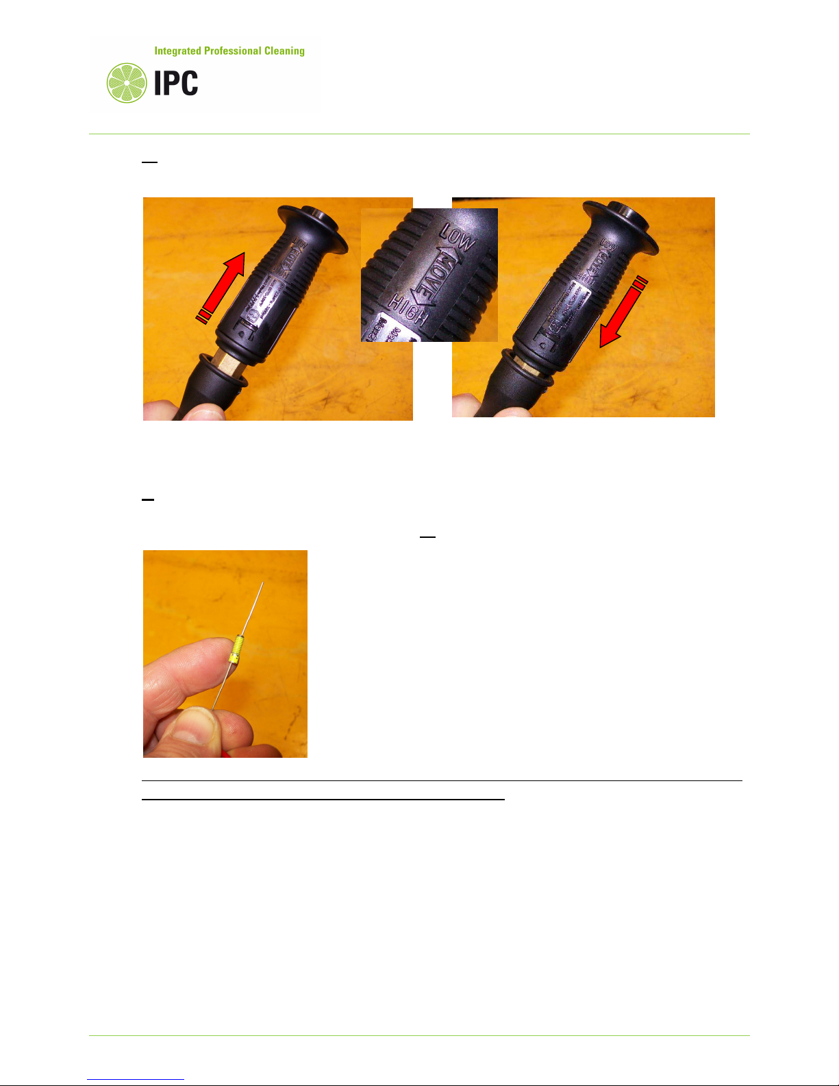
3e Check the lance head (nozzle) position, it must be set in high pressure mode, not in detergent
mode; during the detergent mode the water flow is discharged without pressure.
3f Replace the high pressure nozzle with a new genuine part.
Check the spare part manual to identify the correct nozzle size.
Instruction to disassembling the nozzle: see 2e
We recommend the high pressure nozzle replacement every 200 hours or any time the machine
working pressure become 20% lower than rated pressure.
Detergent mode
High pressure mode
Pag. 20
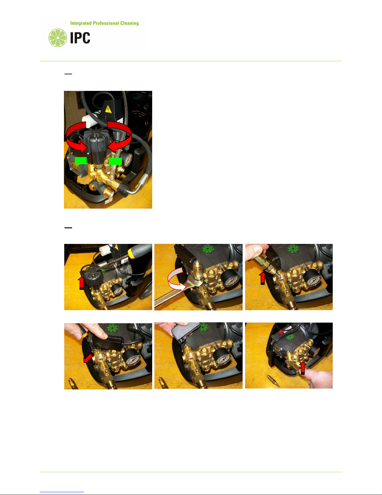
Strip out the switch box
Unscrew the fixation bolt of
the by-pass place at the
high pressure side.
3g Check if the pressure adjusting knob is set to maximum position.
The position maximum is when the knob it fully rotated clockwise.
3h Repair the pressure adjusting valve (by pass valve) by replacing its cartridge that is part of
the dedicated repairing kit.
Remove the knob by pulling it out
Unscrew the valve cartridge
Strip out the valve
Remove the pin holding the switch
MAX
MIN

Pag. 21
Slide out the fixation bolt
of
the by-pass
The by
-
pass valve is so
disassembled, if necessary
it can be replaced with a
new one.
To disassemble the
by-pass
seat, push it out with the
help of a screwdriver, as in
the picture.
To disassemble the by
-
pass
piston, slide out and
remove the locking pin.
To disassemble the by
-
pass
piston, push out and
remove the locking pin.
The by
-
pass system is now completely disassembled
and can be repaired or replaced by a new by-pass repair
kit.
To
reassemble the by
-
pass
whole cartridge to the bypass valve, we recommend
the use of Loctite 542.
Pag. 22
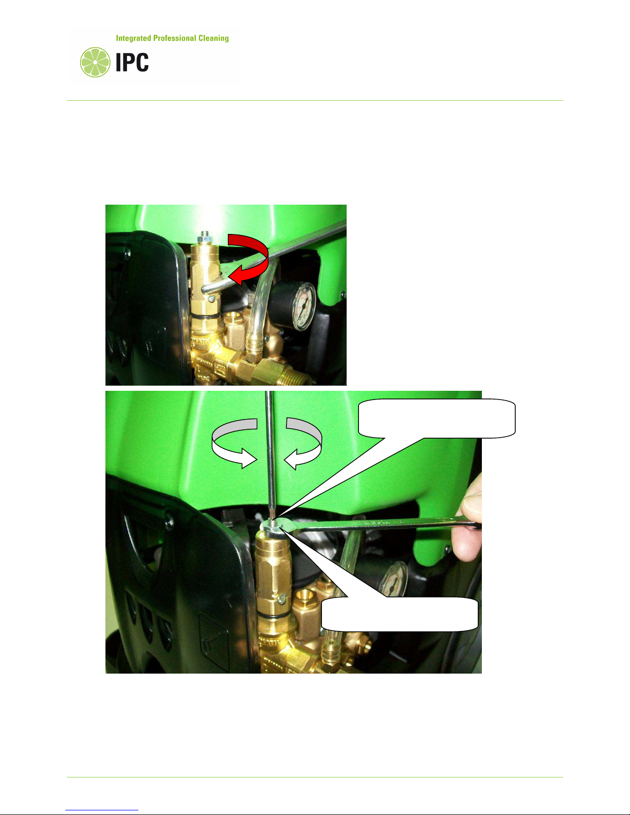
Before adjust the bypass, maximum pressure
setting, ensure that the pressure adjust knob is
completely screwed-in.
After replaced the by-pass valve kit, will be necessary to readjust the machine maximum working
pressure.
The pressure adjustment can be done trough the adjusting screw as indicated in the following
picture:
In order to readjust the machine pressure setting, the lance high pressure nozzle must be
brand new; for setting values, check the pressure characteristics indicated in the machine data
plate.
The working pressure setting can be done looking at the pressure displayed to the machine
pressure gauge.
Nut to lock the maximum
pressure setting
Nut
for
maximum
pressure limit.
- Press
+ Press
Pag. 23
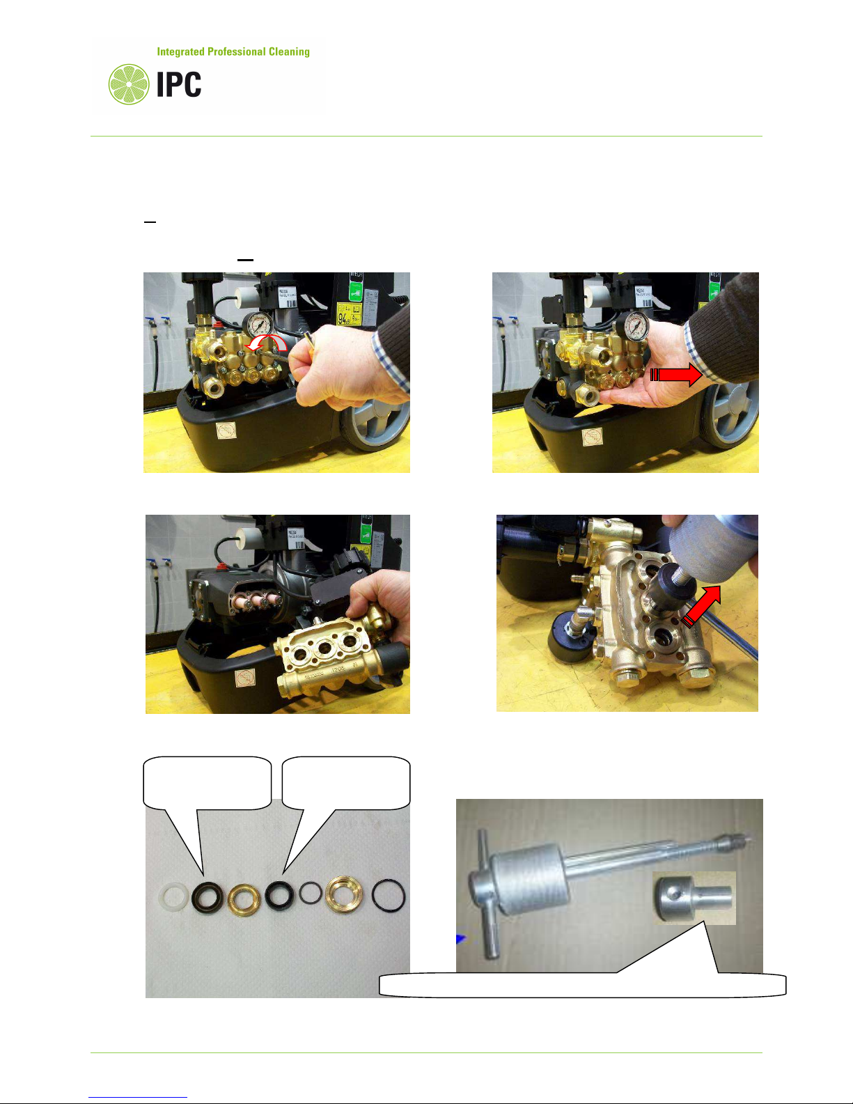
3i Replace the high pressure pump gaskets kit and ensure that the ceramic pistons are not
damaged. If ceramic pistons are cracked, replace them following the instruction as described in
the paragraph 5c.
Unscrew the 6 screws that hold the pump head
Pull out the
pump head
Remove the pump head
Tool head AZMC10761
for gaskets with diameter
15
Extract the seals packing using the extractor
tool part number PVVR31382.
High pressure
gasket
Low pressure
gasket
Pag. 24
4. Poor detergent delivery
4) TRUBLE: Poor detergent delivery
CAUSES: 4a Detergent tap closed/off or clogged
4b Empty detergent tank or nozzle not set in detergent mode
4c The check valve of the detergent circuit is sticky or clogged
4d High pressure outlet pipes clogged or too much extended (over 20 m)
4e Pressure regulator is not set at maximum position
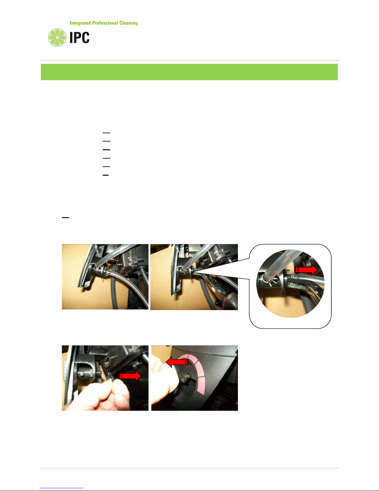
4f Wear and tear of the detergent nozzle
REMEDIES:
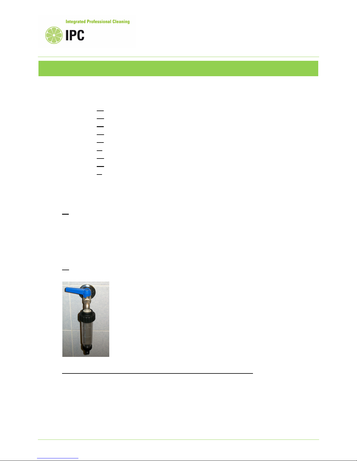
4a Check first if the tap for detergent adjust is open.
If it is open, but doesn’t allow the detergent suction, it may be defective and not functioning (i.e.
clogged), hence replace it with a new one.
The access to the
detergent
tap is possible just after the
machine cover has been
Remove the clips that hold the
pipes.
Remove the detergent tap
holding ring.
Slide out the detergent tap
and replace it if necessary.
Pag. 25
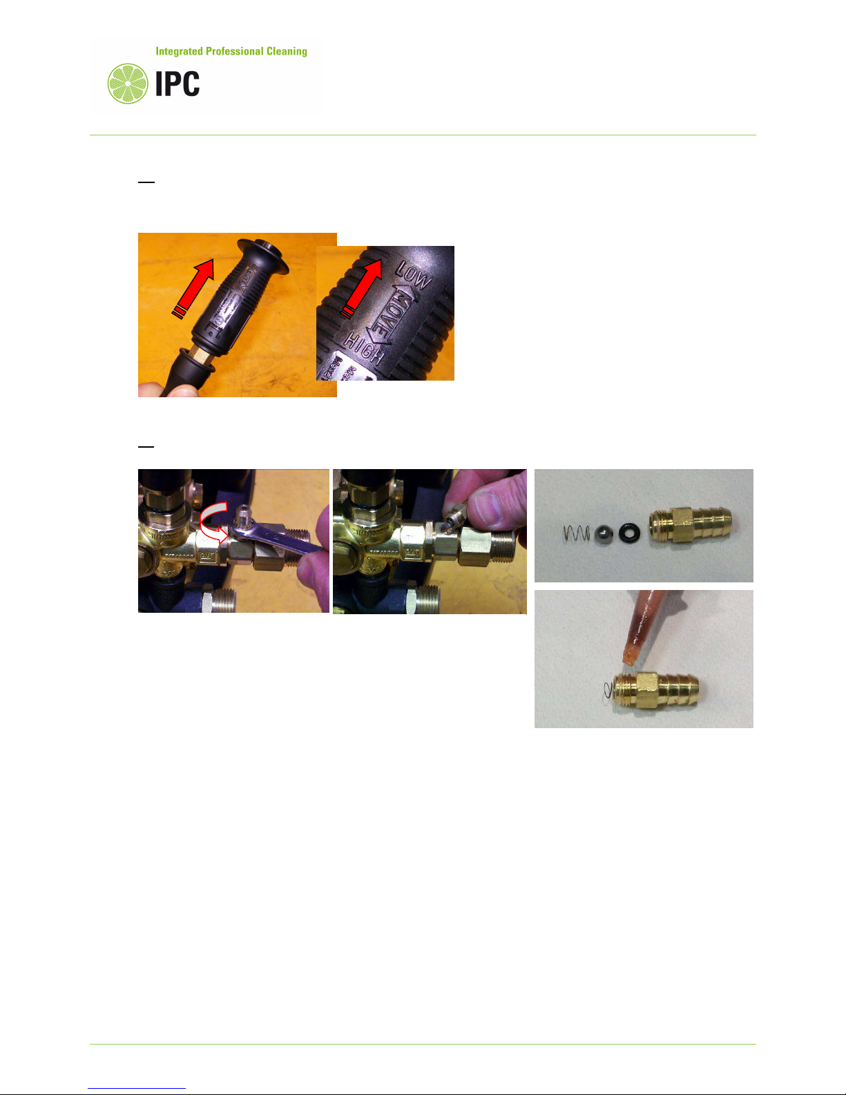
4b Refill with detergent the chemical tank if it is empty; we recommend to use only the
detergents listed in the catalogue.
Switch the head to the lance in detergent mode (LOW).
4c Dismantle and clean the detergent check valve.
Check the cleanness of o-ring, ball and spring that are inside of the valve and replace them if
wear and tear.
Reassemble using some sealing glue, we recommend Loctite 542.
Unscrew and dismantle the detergent check valve
placed at the
machine outlet.

Pag. 26
4d If using an high pressure hose longer than 20 m, the detergent suction can result
compromised, since the Venturi system cannot work.
At the same, a wrong functioning occurs when the high pressure outlet circuit of the machine is
clogged or when using not genuine accessories.
Reduce the length of the high pressure hose at maximum 20 m and ensure that there are not
obstruction to the outlet circuit that causes counter pressure, hence not allowing the functioning
of the Venturi system.
The Venturi system can be wear and tear and in case has to be replaced as following described:
4e Adjust the machine working pressure at maximum position.
Unlock the nut that avoid the
rotation of the outlet fitting.
Unscrew the Venturi system.
Replace, if necessary, the whole
Venturi nozzle and note that the
Venturi holds the outlet check
valve of the by pass.
The outlet check valve is part of
the by-pass and can be wear and
tear, if necessary replace it with a
new one while checking the
Venturi.
Reassemble the Venturi using a
bit of Loctite 542 to seal the
threads.
MAX

Pag. 27
5. Oil and water emulsion phenomena to the high pressure pump oil
5) TROUBLE: The oil, inside of the high pressure pump looks white color (oil and water
emulsion phenomena)
CAUSES: 5a Extremely high environment humidity percentage
5b High pressure pump gaskets worn
5c High pressure pump pistons damaged
REMEDIES:
5a Replace the pump oil using oil quality SAE 20W40:
Unscrew the cap “A” in order to drain the oil from the high pressure pump; wait until the oil being
totally drained out to the recovery tank.
Oil, must be wasted in compliance with the country rules in force for oils. Screw the cap “A” and
refill the oil into the pump from the port “B”; the oil level is detectable from the oil window .
We recommend a proper ventilation of the place where the machine operates, in order to reduce
as much as possible the environment humidity percentage.
OIL WINDOW

Pag. 28
5b Replace the pump water gaskets as described in the section 3i
5c Replacement of the pump pistons:
Check if pistons are cracked
Unscrew the piston lock screw
Slide out the damaged piston
Assemble the new piston and
secure the screw with “Loctite
541” glue.
Tighten
the screw at max. torque 15Nm
Check the o-ring wear
If the o
-
ring is wear and tear
replace it with a new one.
Max. torque 15 Nm

Pag. 29
6. The total stop system doesn’t intervenes
(only for machines having this option)
6) TROUBLE: When the spray gun trigger is released, the pump and motor unit does not stop
automatically or does not restart, when the trigger is reactivated.
CAUSES: 6a Water leaks from the high pressure outlet circuit.
6b Micro-switch of the by-pass valve, or contactor, not functioning.
REMEDIES:
6a Check the if the outlet check valve, placed at the outlet of the by-pass , is worn or teared.
If damaged, replace the whole check valve or only the o-ring if damaged.
Check and remove any water leak from the outlet circuit and particularly check the high pressure
hose couplings and the spray gun.
When the spray gun trigger is released, the outlet circuit is under pressure and this is necessary
to maintain the machine in total stop phase. Any water leak, can cause the restart of the machine
and as consequence the total stop failure.
6b Check the micro-switch of the by-pass valve and the piston that activates the switch as
described in the section 1c.
Check the contactor as described in the section 1d.
The outlet check valve is part of
the by-pass and can be wear and
tear, if necessary replace it with a
new one.

Pag. 30
Periodical maintenance
Every
day
Every
50h
Every
100h
Every
200h
Every
300h
Every
500h
Every
year
Check the power cord and the high pressure quick couplings.
First pump oil replac ement
P u m p o i l r e p l ac e m e n t
Water feedi ng filters clean ing
Pump’s water gaskets replacement
High pressure nozzle replacement
Check and adjust of the safety devices or components
Repairing kits
For a quicker and easier maintenance and repair of this model, some repair kits are available as
following shown.
In order to identify their part number accordingly to the machine model, please refer to this machine's
spare parts manual.
Pump gasket kit
Pump valves kit
Pump oil seals kit
 Loading...