

Page 1

INSTALLING, OPERATING, AND MAINTAINING
INSTALLING, OPERATING, AND MAINTAINING
INSTALLING, OPERATING, AND MAINTAININGINSTALLING, OPERATING, AND MAINTAINING
MODEL D1086/D280
5 AMP GENERATOR FIELD CONTROL
WITH ‘S’ SHAPE PATTERN
GENERATOR
INSTRUCTION MANUAL # 910-1252-003
Page 2

INSTALLING, OPERATING AND MAINTAINING
THE MODEL D1086/D280
5 AMP GENERATOR
2
FIELD CONTROL
WITH ‘S’ SHAPE PATTERN GENERATOR
REVISION: 2.1
OCTOBER 2003
Page 3

TABLE OF CONTENTS
INTRODUCTION...........................................................................................................................................................................4
SAFETY.......................................................................................................................................................................................5
WARRANTY...............................................................................................................................................................................5
Q.C. TESTING.............................................................................................................................................................................5
STORAGE....................................................................................................................................................................................6
SECTION TWO..............................................................................................................................................................................7
GENERAL DESCRIPTION...........................................................................................................................................................7
INTRODUCTION........................................................................................................................................................................7
CONTROL SPECIFICATIONS...................................................................................................................................................7
Speed Settings:.........................................................................................................................................................................7
Acceleration and Deceleration Rates and Configuration: ......................................................................................................8
‘S’ Shape Curve Knee Settings ................................................................................................................................................ 8
Dead Zone Time Delay............................................................................................................................................................9
3
SECTION THREE........................................................................................................................................................................10
INSTALLATION INSTRUCTIONS ...........................................................................................................................................10
INTRODUCTION......................................................................................................................................................................10
INPUT CONNECTIONS...........................................................................................................................................................10
SPEED SELECTION CONTACTS ...........................................................................................................................................11
RUN CONTACTS......................................................................................................................................................................11
SUPPLY VOLTAGE .................................................................................................................................................................11
OUTPUT POWER CONNECTIONS ........................................................................................................................................11
GENERATOR FIELD CONNECTION.....................................................................................................................................11
FEEDBACK CONNECTION....................................................................................................................................................12
Page 4

INTRODUCTION
Thank you for purchasing an IPC Automation elevator control.
At IPC we are committed to designing and manufacturing high quality controls that meet or exceed our
customers needs. This manual provides the information you will need in order to properly install, operate and
troubleshoot the Model D1086 5 Amp Generator Field Control with ‘S’ Shape Pattern Generator. Please
read this manual completely before attempting to install or operate the Model D1086/D280.
Please feel free to call IPC Automation with any questions you may have BEFORE performing installation
or start-up.
IPC Automation
4615 West Prime Parkway
McHenry, IL 60050
4
Phone: (815) 759-3934
Fax: (815) 363-1641
Page 5

SAFETY
There are certain fundamental warnings, which must be kept in mind at all times. These include:
THE D1086/D280 SHOULD BE INSTALLED, ADJUSTED AND SERVICED BY QUALIFIED
ELECTRICAL MAINTENANCE PERSONNEL WHO ARE FAMILIAR WITH THE
CONSTRUCTION AND OPERATION OF ALL EQUIPMENT IN THE ELEVATOR SYSTEM.
PERSONAL INJURY AND/OR EQUIPMENT DAMAGE MAY OCCUR IF INDIVIDUALS ARE
NOT FAMILIAR WITH THE HAZARDS REZULTING FROM IMPROPER OPERATION.
THE USER IS RESPONSIBLE FOR CONFORMING WITH THE NATIONAL ELECTRICAL
CODE WITH RESPECT TO MOTOR, CONTROLLER AND OPERATOR DEVICE
INSTALLATION, WIRING AND START-UP. THE USER IS ALSO RESPONSIBLE FOR
UNDERSTANDING AND APPLYING ALL OTHER APPLICABLE LOCAL CODES WHICH
GOVERN SUCH PRACTICES AS WIRING PROTECTION, GROUNDING, DISCONNECTS AND
OVERCURRENT PROTECTION.
5
WARRANTY
Standard conditions of sale for the company include a Statement of Warranty, which covers the control
equipment. This Statement of Warranty covers all new equipment.
The D1086/D280 Generator Field Control with ‘S’ Shape Pattern Generator has been designed as a
standard product to meet the general criteria for providing an ‘S’ shape reference signal to be used
in conjunction with a solid state generator field control for controlling Motor Generators for Elevator
use. IPC does not warrant that the control will meet all application requirements, codes and safety
standards.
Q.C. TESTING
Each unit is carefully tested at the factory prior to shipment. The control must pass rigorous static and
dynamic performance tests as well as a final inspection for quality of workmanship. A unit is allow to ship
only after passing all aspects of this Q.A. testing and inspection process.
Page 6

STORAGE
Should it become necessary to store th e co ntrol for any length of ti me, plea se k eep the f ollo wing precautions
in mind to ensure the proper operation of the control.
" Store the control in a clean, dry (non-corrosive ) lo cation that is pr otected from sudden temper atu re
changes, high levels of moisture, shock and vibration.
" Ambient temperature should be maintained between 0 and 50 degrees Centigrade.
" The control should be covered to protect from dust and dirt conta mination (utilize origina l shipment
packaging if available).
6
Page 7

SECTION TWO
GENERAL DESCRIPTION
INTRODUCTION
The Model D1086/D280 Generator Field Control, in its typical operating mode, varies the Generator field
voltage in proportion to an input command signal. Adjustment potentiometers are provided for adjusting
six contact-selectable speed setpoints (including high speed), two acceleration rates and three deceleration
rates. Four potentiometers are also provided for the individual adjustment of the ‘S’ Shape Curve knees.
All potentiometers used for speed, acceleration, deceleration and knee adjustment are four-turn
potentiometers.
7
CONTROL SPECIFICATIONS
Input Supply: Input Line Voltage – 208 to 230 Volts AC Single Phase 50/60Hz
Output: Zero (0) to 180 Volts DC at 5 Amps.
Dimensions: Length: 10.00 inches
Width: 7.75 inches
Height: 5.00 inches
Speed Settings:
Speed
Pot Termina
SP1 TB3-22 0 to 15% 0 to 1.5 VDC
SP2 TB3-23 0 to 25% 0 to 2.5 VDC
SP3 TB3-24 0 to 100% 0 to 10 VDC
SP4 TB3-25 0 to 100% 0 to 10 VDC
SP5 TB3-26 0 to 100% 0 to 10 VDC
HI TB3-27 100% Fixed 10 VDC
Adjustable
% of Full
Speed
l
Range of Input
Reference
Voltage
Speed settings SP1 through SP5 can be adjusted withou t an UP or Down sig nal appl ied or a speed contact
pulled in. Monitor the voltage between each speed terminal connection and common (TB1-3) to set each
speed.
Page 8

Acceleration and Deceleration Rates and Configuration:
The D1086/D280 ‘S’ Shape Curve Board is factory preset with the J1 jumper in the 1-2 position. This
configuration provides two Acceleration rates (ACC1, ACC2) and three Deceleration rates (DCC1, DCC2,
and DCC3).
Figure One
Moving the jumpe r to the 2-3 position ch ang es the ACC2 poten tiome ter to a fourth De c ele r a tio n po t. In this
position there are four deceleration rates (DCC1, DCC2, DCC3, and ACC2) and only one Acceleration rate
pot (ACC1).
8
Figure Two
‘S’ Shape Curve Knee Settings
Figure Three
The ‘S’ shape of the output pattern is controlled by potentiometers P1 through P4. The curve will be very
smooth with the pots fully counter-clockwise and very sharp with the pots fully clockwise. These
adjustments will have more effect when the acceleration or deceleration rates are slow and will have less
effect when the acceleration and deceleration rates are fast.
Page 9

Dead Zone Time Delay
The Dead Z o ne Ti me D e la y allows t he c on tr ol re fe rence output si gn a l at TB2-9 to ra mp to zer o- sp e e d du ring
the interval between the drop out of the Run input direction signal, and the engagement of the mechanical
brake. The time delay circuit will produce a del ay in forcing the reference signal at TB 2-9 from the selected
speed (SP1-5,HI) to Zero vo lts up on dr opp ing the UP or DN i npu t c ont act s (TB3-35,36,37). This delay time
is adjustable from 10 milliseconds to 0.5 seconds with the R54 potentiometer.
R54 Full Counter-clockwise 0.5 second delay
R54 Full Clockwise 10 millisecond delay
9
Page 10

SECTION THREE
INSTALLATION INSTRUCTIONS
INTRODUCTION
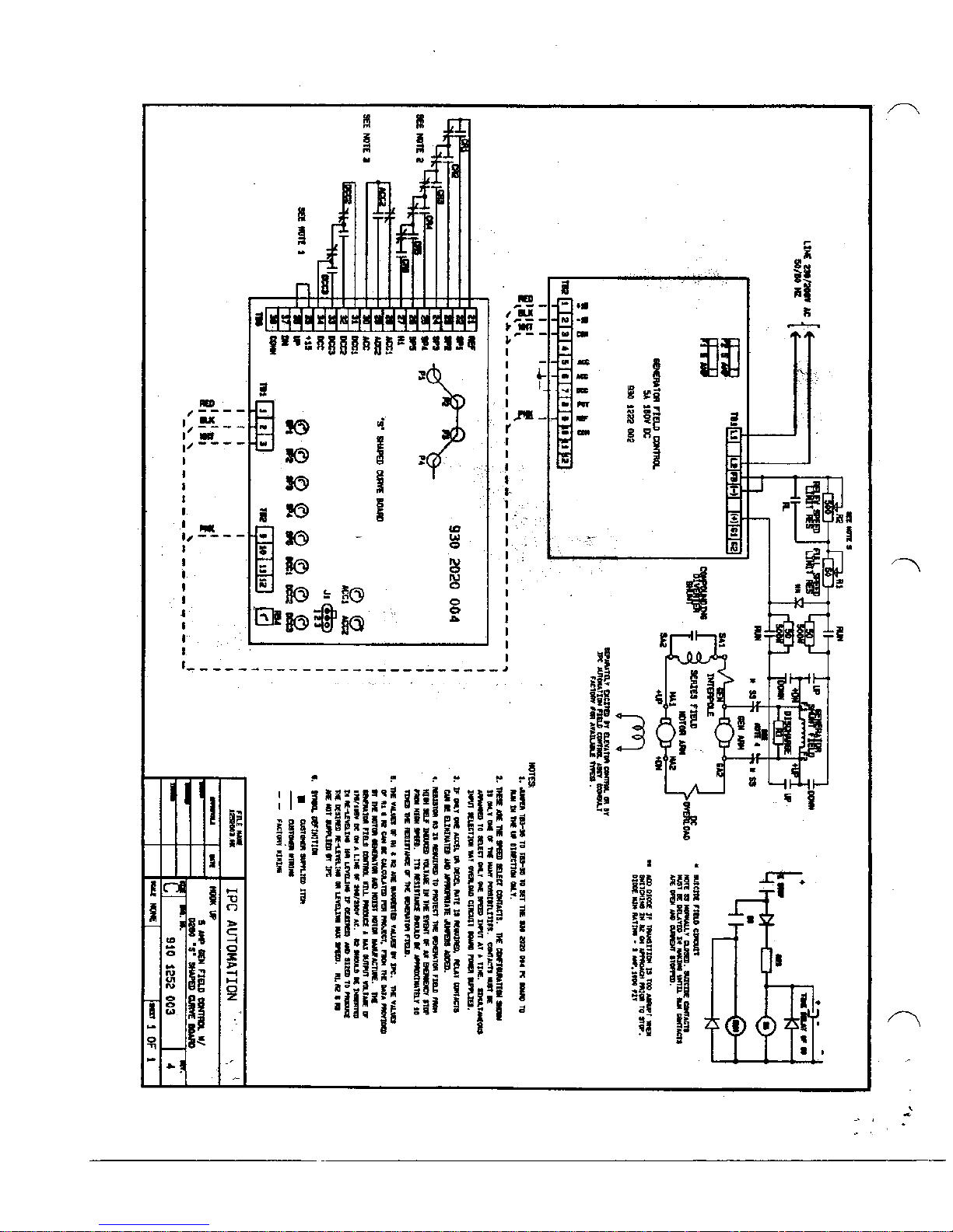
The following section contains hook-up notes and drawings for the model D1086/D280 Generator Field
Control with ‘S’ Shape Curve. The hook-up notes refer to the hook-up diagram supplied as part of this
manual.
THE D1086/D280 SHOULD BE INSTALLED, ADJUSTED AND SERVICED BY QUALIFIED
ELECTRICAL MAINTENANCE PERSONNEL WHO ARE FAMILIAR WITH THE
CONSTRUCTION AND OPERATION OF ALL EQUIPMENT IN THE ELEVATOR SYSTEM.
PERSONAL INJURY AND/OR EQUIPMENT DAMAGE MAY OCCUR IF INDIVIDUALS ARE
NOT FAMILIAR WITH THE HAZARDS REZULTING FROM IMPROPER OPERATION.
10
THE USER IS RESPONSIBLE FOR CONFORMING WITH THE NATIONAL ELECTRICAL
CODE WITH RESPECT TO MOTOR, CONTROLLER AND OPERATOR DEVICE
INSTALLATION, WIRING AND START-UP. THE USER IS ALSO RESPONSIBLE FOR
UNDERSTANDING AND APPLYING ALL OTHER APPLICABLE LOCAL CODES WHICH
GOVERN SUCH PRACTICES AS WIRING PROTECTION, GROUNDING, DISCONNECTS AND
OVERCURRENT PROTECTION
INPUT CONNECTIONS
All connections are referenced to the hook-up diagram. The configuration that is shown in the hook-up
diagram is not a recommendation, it is only one of many possibilities.
Page 11
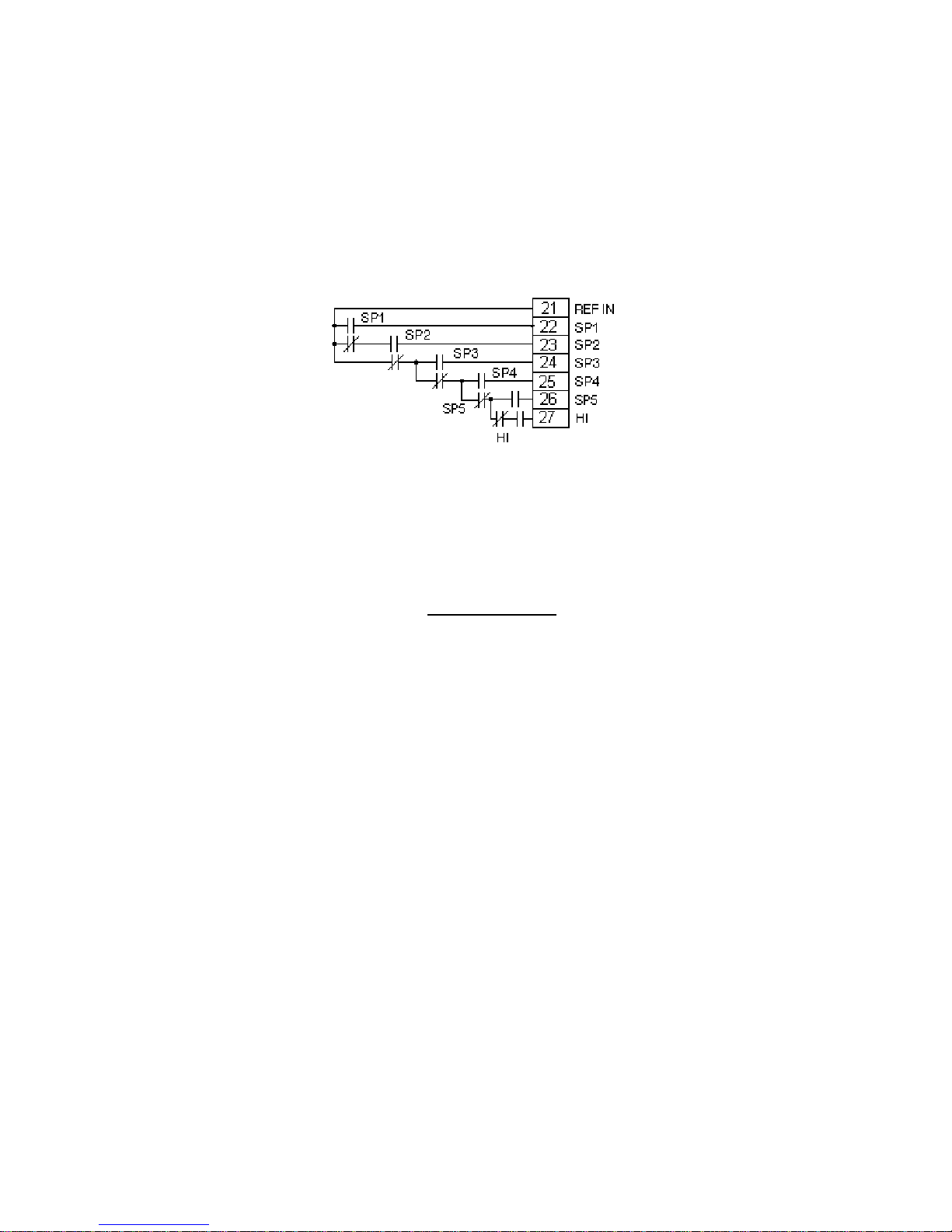
SPEED SELECTION CONTACTS
Contacts must be arranged to select only one speed input at a time. Simultaneous input selection may
overload the circuit board power supplies.
11
Figure Four
RUN CONTACTS
The D1086 is a Uni-Directional control. In order to work properly with the D1086, the D280 ‘S’ Shape
Curve Board must be configured to run in the UP direction only. If you would like to utilize the Dead Zone
Time Delay feature of the D280 board, y o u may insert a contact from terminal 35 (+15 ) to t ermin al 36 (UP).
This contact must close to enable the elevator to run and open to enable the Dead Zone feature (during the
setting of the brake). If you do not wish to utilize the Dead Zone feature, a jumper may be used to configure
the D280 board to run in the UP direction.
SUPPLY VOLTAGE
Connect a 208 to 23 0 V olt 50 /60 Hz Sin g le Ph ase AC line to L 1 a nd L2 of TB1 on th e D 108 6 Board (bottom
Board). Internal 5 Amp fusing is provided on the D1086 board.
OUTPUT POWER CONNECTIONS
Refer to the hook-up diagram for all output power connections. The use of 16 AWG or higher rated wire
for all Generator Field connections is recommended.
GENERATOR FIELD CONNECTION
Connect the generator field to “+” and “-“ on TB1 of the D1086 (bottom) Board. Ensure proper polarity of
the field connections to avoid improper operation or damage to the control.
Page 12

FEEDBACK CONNECTION
Connect a jumper from “-“ to “FB” on TB1 of the D1086 (bottom) board.
Failure to install this jumper will cause the control to produce full output voltage when any speed is
selected.
12
Page 13
13
 Loading...