


CT51 - CT71
MANUALE ISTRUZIONI PER L’USO
OPERATOR’S MANUAL
MANUEL D’INSTRUCTIONS
BEDIENUNGSANLEITUNG
MANUAL DE INSTRUCCIONES
BRUKERHÅNDBOK
GEBRUIKERSHANDLEIDING
MANUAL DE UTILIZAÇÃO
INSTRUKTIONSBOK
МАШИНА ДЛЯ МОЙКИ И СУШКИ ПОЛОВ
KULLANIM KILAVUZU
РЪКОВОДСТВО ЗА ЕКСПЛОАТАЦИЯ
BRUGERMANUAL
Consultare attentamente questo manuale prima di procedere a qualsiasi intervento sulla macchina
Read this manual carefully before carrying out any work on the machine
Lire attentivement ce manuel avant toute intervention sur la machine
Vorliegendes Handbuch vor jedem Eingri an der Maschine aufmerksam durchlesen
Consulte detenidamente este manual antes de llevar a cabo cualquier trabajo en la máquina
Konsulter denne håndboken nøye før du går i gang med noen som helst type inngrep på maskinen
Raadpleeg deze handleiding aandachtig alvorens met enige werkzaamheid aan de machine te beginnen
Consulte atentamente este manual antes de efectuar qualquer intervenção na máquina
Läs noggrant igenom denna handbok innan du utför något som helst ingrepp på maskinen
Внимательно ознакомьтесь с данной инструкцией до проведения любой работы с машиной
Makine ile herhangi bir işlem yapmadan önce bu kılavuzu dikkatle okuyun
Прочетете внимателно това ръководство, преди да извършите каквато и да е операция по машината
Læs dette brugervejledning grundigt før der udføres arbejde på maskinen

ENGLISH
(Translation of original instructions)
TECHNICAL CHARACTERISTICS CT51 ............................................................................................................................. 3
TECHNICAL CHARACTERISTICS CT71 ............................................................................................................................. 4
SAFETY SYMBOLS .............................................................................................................................................................. 5
MACHINE DIMENSIONS ...................................................................................................................................................... 5
GENERAL INFORMATION ................................................................................................................................................... 6
Purpose of this manual .................................................................................................................................................................................................. 6
Identifying the machine .................................................................................................................................................................................................. 6
Documentation provided with the machine .................................................................................................................................................................... 6
TECHNICAL INFORMATION ................................................................................................................................................ 7
General description ........................................................................................................................................................................................................ 7
Key ................................................................................................................................................................................................................................. 7
Hazard areas.................................................................................................................................................................................................................. 7
Accessories .................................................................................................................................................................................................................... 7
SAFETY INFORMATION ...................................................................................................................................................... 8
Safety precautions ......................................................................................................................................................................................................... 8
MOVEMENT AND INSTALLATION ..................................................................................................................................... 10
Lifting and transporting the packaged machine ............................................................................................................................................................ 10
Delivery checks ............................................................................................................................................................................................................. 10
Unpacking: .................................................................................................................................................................................................................... 10
Batteries (Battery version)............................................................................................................................................................................................. 10
Batteries: preparation .................................................................................................................................................................................................... 10
Batteries: installation and connection............................................................................................................................................................................ 11
Batteries: removal ......................................................................................................................................................................................................... 11
Choosing a battery charger ........................................................................................................................................................................................... 11
Preparing the battery charger ...................................................................................................................................................................................... 11
Squeegee installation and adjustment .......................................................................................................................................................................... 12
Squeegee adjustment ................................................................................................................................................................................................... 12
Brush installation ........................................................................................................................................................................................................... 12
Lifting and transporting the machine ............................................................................................................................................................................. 13
Quick head change ....................................................................................................................................................................................................... 13
PRACTICAL GUIDE FOR THE OPERATOR ....................................................................................................................... 14
Preparing the machine for work .................................................................................................................................................................................... 14
Controls ......................................................................................................................................................................................................................... 14
Working ......................................................................................................................................................................................................................... 16
Some useful tips to get the most from your scrubber drier ........................................................................................................................................... 16
Emptying the collection tank ......................................................................................................................................................................................... 16
Emptying the water/detergent tank ............................................................................................................................................................................... 17
Emptying the roller head bin ......................................................................................................................................................................................... 17
Filling the water/detergent tank ..................................................................................................................................................................................... 17
Filling the Chem-Dose tank (accessory) ....................................................................................................................................................................... 17
Finishing work ............................................................................................................................................................................................................... 17
Moving the machine when not in operation................................................................................................................................................................... 17
MAINTENANCE INSTRUCTIONS ....................................................................................................................................... 18
Maintenance - General rules ......................................................................................................................................................................................... 18
Cleaning the suction motor air lter............................................................................................................................................................................... 18
Cleaning the debris container ....................................................................................................................................................................................... 18
Cleaning the dirty water tank oat ................................................................................................................................................................................. 18
Cleaning the water/detergent tank lter ........................................................................................................................................................................ 18
Fuses: replacing ............................................................................................................................................................................................................ 19
Battery maintenance and charging ............................................................................................................................................................................... 19
Replacing the squeegee blades .................................................................................................................................................................................... 20
Periodic checks ............................................................................................................................................................................................................. 20
PERIODS OF INACTIVITY .................................................................................................................................................. 20
TROUBLESHOOTING ......................................................................................................................................................... 21
DISPLAY ALARMS .............................................................................................................................................................. 22
TECHNICAL MENU CT51 - 71 ...........................................................................................................................................23
ENGLISH
2

TECHNICAL CHARACTERISTICS CT51
C55
115V
Cleaning width mm 530 530 530 530 530 550 600 600 685 685 530 685
Squeegee width mm 816 816 816 816 816 816 816 816 842 842 816 842
C55
230V
B55 BT55 XP55 XP55R BT60 XP60 BT70 XP70
BT55
ECS
BT70
ECS
Cleaning capacity per hour m
Number of brushes n° 1 1 1 1 1 2 2 2 2 2 1 2
Brush diameter mm 530 530 530 530 530 100 310 310 345 345 530 345
Maximum brush pressure gr/cm
Brush rotation speed g/1° 155 155 150 150 150 1360 200 200 200 200 600 600
Brush motor power W 450 450 400 400 400 850x2 400x2 400x2 400x2 400x2 600 450
Drive motor power W / / / 200 200 200 200 200 200 200 200 200
Maximum speed Km/h 3,5 3,5 3,5 5,5 5,5 5,5 5,5 5,5 5,5 5,5 5,5 5,5
Suction motor power W 450 450 380 380 380 380 380 380 380 380 380 380
Solution tank L 50 50 50 50 50 50 50 50 50 50 50 50
Dirty water tank L 50 50 50 50 50 50 50 50 50 50 50 50
Rear wheel diameter mm 200 200 200 200 200 200 200 200 200 200 200 200
Maximum slope % 2 2 2 2 2 2 2 2 2 2 2 2
Gross weight (GVW) Kg 219,4 227,1 227,1 235,1 235,1 232,6 232,6
Transport weight Kg 50 50 138 138 138 138 138 138 138 138 138 138
2
/h 1850 1850 1850 2915 2915 3025 3316 3316 3767 3767
2
14,3 14,3 11,6 11,6 16,2 70,2 30 27,3 21,1 26,6
Number of batteries n° / / 2 2 2 2 2 2 2 2 2 2
Battery voltage V / / 12 12 12 12 12 12 12 12 12 12
Individual battery capacity Ah (5h) / / 105 105 105 105 105 105 105 105 105 105
220 240V
50/60Hz
X=1327
Y=1033
Z=563
360
360
x344
x300
1365
x695
x1146
2,5 2,5 2,5 2,5 2,5 2,5 2,5 2,5 2,5 2,5 2,5 2,5
/ / / / / / / / / /
/ / / / / / / / / /
24 24 24 24 24 24 24 24 24 24
X=1327
Y=1033
X=1327
Y=1033
Z=563
360
x344
x300
1365
x695
x1146
58 58 59 59 59
1,4 1,4
0,7 0,7
Z=563
360
x344
x300
1365
x695
x1146
X=1327
Y=1033
Z=563
360
x344
x300
1365
x695
x1146
X=1288
Y=1033
Z=640
360
x344
x300
X=1279
Y=1033
Z=653
360
x344
x300
1335
x780
x1146
X=1279
Y=1033
Z=653
360
x344
x300
1335
x780
x1146
X=1297
Y=1033
Z=735
360
x344
x300
1335
x780
x1146
X=1297
Y=1033
Z=735
360
x344
x300
1335
x780
x1146
mm
LpA
ahv
115V
60Hz
X=1327
Y=1033
Z=563
x344
x300
1365
x695
x1146
K
2
2
2
2
Power system voltage V
Machine dimensions mm
Battery compartment dimensions (length,
width, height)
Packed size (length, width, height) mm
Sound pressure - Annex DD (Emission of
acoustical noise) EN 60335-2-72: 2012
Measurement uncertainty
Vibration level (hand) - IEC 60335-2-72
Measurement uncertainty, k m/sec
Vibration level (body) - IEC 60335-2-72
Measurement uncertainty, k m/sec
Maximum water and detergent temperature °C 55 55 55 55 55 55 55 55 55 55 55 55
(dBA)
(dBA)
m/sec
HBV
m/sec
Gross weight (GVW): maximum permitted weight of the machine at full load, ready for use, plus its net load. The gross weight of the vehicle includes,
where applicable, full clean water tanks, empty dirty water tanks (half full for recycling systems), empty dust collection sacks, hopper lled to rated
capacity, the largest recommended batteries, all accessories such as cables, pipes and hoses, detergents, sweepers and brushes.
Transport weight: weight of the machine for transport, which includes the batteries but excludes the options (for example, the driver’s cabin, the
FOPS, the second and third side brush, the front brush attachment), clean water (for scrubbers or combined machines) and the standard weight of
an operator (75 kg).
Data subject to variation without warning.
ENGLISH
3

TECHNICAL CHARACTERISTICS CT71
C55
115V
Cleaning width mm 530 530 530 530 530 550 600 600 685 685 530 685
Squeegee width mm 816 816 816 816 816 816 816 816 842 842 816 842
C55
230V
B55 BT55 XP55 XP55R BT60 XP60 BT70 XP70
BT55
ECS
BT70
ECS
Cleaning capacity per hour m
2
/h 1850 2915 2915 3025 3316 3316 3767 3767 2915 3767
Number of brushes n° 1 1 1 1 1 2 2 2 2 2 1 2
Brush diameter mm 530 530 530 530 530 100 310 310 345 345 530 345
Maximum brush pressure gr/cm
2
14,3 14,3 11,6 11,6 16,2 70,2 30 27,3 21,1 26,6 13,4 20,9
Brush rotation speed g/1° 155 155 150 150 150 1360 200 200 200 200 600 600
Brush motor power W 450 450 400 400 400 850x2 400x2 400x2 400x2 400x2 600 450
Drive motor power W / / / 200 200 200 200 200 200 200 200 200
Maximum speed Km/h 3,5 3,5 3,5 5,5 5,5 5,5 5,5 5,5 5,5 5,5 5,5 5,5
Suction motor power W 450 450 380 380 380 380 380 380 380 380 380 380
Solution tank L 65 65 65 65 65 65 65 65 65 65 65 65
Dirty water tank L 70 70 70 70 70 70 70 70 70 70 70 70
Rear wheel diameter mm 200 200 200 200 200 200 200 200 200 200 200 200
Maximum slope % 2 2 2 2 2 2 2 2 2 2 2 2
Gross weight (GVW) Kg 235,2 242,9 242,9 250,9 250,9 248,4 248,4 246,2 251,8
Transport weight Kg 153 153 153 153 153 153 153 153 153 153
Number of batteries n° / / 2 2 2 2 2 2 2 2 2 2
Battery voltage V / / 12 12 12 12 12 12 12 12 12 12
Individual battery capacity Ah (5h) / / 105 105 105 105 105 105 105 105 105 105
Power system voltage V
Machine dimensions mm
Battery compartment dimensions (length,
width, height)
mm
Packed size (length, width, height) mm
Sound pressure - Annex DD (Emission of
acoustical noise) EN 60335-2-72: 2012
Measurement uncertainty
Vibration level (hand) - IEC 60335-2-72
LpA
(dBA)
K
(dBA)
ahv
m/sec
Measurement uncertainty, k m/sec
Vibration level (body) - IEC 60335-2-72
HBV
m/sec
Measurement uncertainty, k m/sec
115V
60Hz
x1033
x1146
2
2
2
2
220 -
1327
x563
360
x344
x300
1365
x695
240V
50/60Hz
1327
x563
x1033
360
x344
x300
1365
x695
x1146
24 24 24 24 24 24 24 24 24 24
1327
x563
x1033
x344
x300
1365
x695
x1146
360
1327
x563
x1033
360
x344
x300
1365
x695
x1146
1327
x563
x1033
360
x344
x300
1365
x695
x1146
1288
x640
x1033
360
x344
x300
1335
x780
x1146
1279
x653
x1033
360
x344
x300
1335
x780
x1146
1279
x653
x1033
360
x344
x300
1335
x780
x1146
1297
x735
x1033
360
x344
x300
1335
x780
x1146
1297
x735
x1033
360
x344
x300
1335
x780
x1146
1327
x563
x1033
1365
x695
x1146
x1033
58 58 59 59 59
2,5 2,5 2,5 2,5 2,5 2,5 2,5 2,5 2,5 2,5 2,5 2,5
1,4 1,4
0,7 0,7
/ / / / / / / / / /
/ / / / / / / / / /
1297
x735
1335
x780
x1146
Maximum water and detergent temperature °C 55 55 55 55 55 55 55 55 55 55 55 55
Gross weight (GVW): maximum permitted weight of the machine at full load, ready for use, plus its net load. The gross weight of the vehicle includes,
where applicable, full clean water tanks, empty dirty water tanks (half full for recycling systems), empty dust collection sacks, hopper lled to rated
capacity, the largest recommended batteries, all accessories such as cables, pipes and hoses, detergents, sweepers and brushes.
Transport weight: weight of the machine for transport, which includes the batteries but excludes the options (for example, the driver’s cabin, the
FOPS, the second and third side brush, the front brush attachment), clean water (for scrubbers or combined machines) and the standard weight of
an operator (75 kg).
Data subject to variation without warning.
ENGLISH
4

MACHINE DIMENSIONS
Y
A
Z
Y
Z
X-Y-Z: See “TECHNICAL SPECIFICATIONS” table
Y
A
X
X
SAFETY SYMBOLS
Z
X
WARNING! RISK OF CUTTING
WARNING! RISK OF CRUSHING LIMBS
WARNING! RISK OF ABRASION
WARNING! RISK OF ENTANGLEMENT
WARNING! RISK OF ACID BURNS
WARNING! RISK OF BURNS
MAXIMUM SLOPE
OPERATOR’S MANUAL, OPERATING INSTRUCTIONS
READ THE OPERATOR’S MANUAL
DIRECT CURRENT SYMBOL
INSULATION CLASS, THIS CLASSIFICATION ONLY APPLIES TO
MACHINES POWERED BY BATTERIES.
EARTHING POINT.
EXTERNAL BATTERY CHARGER CONNECTION POINT.
DO NOT WASH THE MACHINE BY SPRAYING DIRECTLY
WITH WATER OR USING HIGH PRESSURE WATER JETS.
ENGLISH
5

GENERAL INFORMATION
Model :
Vac :
W :
A :
Hz :
Ser.N :
Date :
IP :
Kg :
Purpose of this manual
This manual has been written by the Manufacturer and is an integral part of the machine1.
It denes the purpose for which the machine has been designed and constructed and contains all the information required by operators2.
In addition to this manual, which contains information for operators, other publications are available providing specic information for maintenance
personnel3.
The terms “right” and “left”, “clockwise” and “anti-clockwise” refer to the forward movement of the machine.
Constant compliance with the instructions provided in this manual guarantees the safety of the operator and the machine, ensures low running costs
and high quality results and extends the working life of the machine. Failure to follow these instructions may lead to injury to the operator or damage
to the machine, oor and environment.
To nd the topic that interests you more rapidly, consult the list of contents at the beginning of the manual.
Parts of the text requiring special attention are printed in bold and preceded by the symbols illustrated and described here.
! DANGER
Indicates the need for attention in order to avoid a series of consequences which could cause death or serious injury to personnel.
Indicates the need for attention in order to avoid a series of consequences which could cause damage to the machine or work environment
! WARNING
or nancial loss.
! INFORMATION
Very important instructions
In line with the company’s policy of constant product development and updating, the Manufacturer reserves the right to make modica-
tions without prior notice.
Although your machine may dier appreciably from the illustrations in this document, the correctness and validity of the instructions
contained in this manual are guaranteed.
Identifying the machine
The nameplate provides the following information:
► Model.
► Battery voltage.
► Total rated power.
► Rated current draw.
► Serial number.
► Year of manufacture.
► IP Index of Protection.
► Gross weight (GVW).
► Maximum negotiable gradient.
► Name of manufacturer.
Documentation provided with the machine
► Operator’s manual;
► Certicate of warranty;
► CE certicate of conformity.
1 The denition "machine" replaces the trade name covered by this manual.
2 Persons responsible for using the machine without performing any operations requiring precise technical skills.
3 Persons with experience, technical training and a knowledge of legislation and standards, able to perform all the necessary operations and to
recognise and avoid possible risks in handling, installation, use and maintenance of this machine.
ENGLISH
6

TECHNICAL INFORMATION
General description
This machine is a scrubber drier for washing and drying at, horizontal, smooth or moderately rough, even and obstacle free oors in civil and industrial premises.
The scrubber drier spreads a solution of water and detergent in the correct concentration on the oor and then scrubs it to remove the dirt. By carefully
choosing the detergent and brushes (or abrasive disks) from the wide range of accessories available, the machine can be adapted to a wide range
of combinations of types of oor and dirt.
A suction system incorporated in the machine dries the oor after washing by means of the low pressure generated in the dirty water tank by the
suction motor. The squeegee connected to the tank collects the dirty water.
Key
The main parts of the machine are as follows:
► The tank (g.1-ref.1), contains and carries the mixture of clean water and cleaning product and collects the dirty water picked up from the
oor after washing.
► Control panel (g. 1-ref. 2).
► Head assembly (g. 1-ref. 3): the main element comprises the brushes/rollers which distribute the detergent solution onto the oor and re-
move the dirt.
► Squeegee assembly (g. 1-ref. 4): wipes and dries the oor by collecting the water.
Hazard areas
► Control panel: risk of injury from short circuits.
► Tank assembly: when using certain detergents, danger of irritation for eyes, skin, mucous membranes and respiratory tract and of asphyxia.
Danger represented by the dirt collected from the environment (germs and chemical substances). Danger of crushing between the two tanks
when the dirty water tank is replaced on top of the detergent tank.
► Washing head assembly: danger due to brush rotation.
► Front/rear wheels: risk of crushing between the wheels and chassis.
► Motor/battery compartment: danger of short circuit between the battery poles and presence of hydrogen during charging.
Accessories
► Soft, hard and abrasive brushes.
► Chem-Dose tank.
► S.P.E. battery charger CBHD3.
1
2
1
3
4
ENGLISH
7

SAFETY INFORMATION
Safety precautions
! DANGER
Read the “User Manual” carefully before start-up and use or before performing maintenance or any other work on the machine.
! WARNING
Rigorously follow all the instructions in this Manual (in particular those marked “Danger!” and “Warning!”). Also respect the labels applied
to the machine (see the “Safety symbols” chapter.
The Manufacturer declines all liability for injury to persons or damage to property resulting from failure to follow instructions.
► Only one operator may operate the machine.
► The machine must be used exclusively by persons trained in its use and/or who have demonstrated their ability and have been expressly
authorised to use it.
► The machine must not be used by minors.
► Always pay attention to other people, especially children, in the place where you are working.
► Children must be supervised to make sure they do not play with the machine.
► The machine is not intended for use by persons (including children) with reduced physical, sensory or mental capabilities, or lack of expe-
rience and knowledge, unless they are supervised by a person responsible for their safety and have received instruction in the use of the
machine.
► The machine must not be used for purposes other than those for which it was expressly designed.
► Scrupulously respect all safety standards and conditions applicable to the type of building in which the machine is to be operated (e.g.: phar-
maceutical companies, hospitals, chemical companies, etc.).
► This machine is intended for use in commercial applications, such as hotels, schools, hospitals, factories, shops and commercial premises.
► The machine must only be used indoors.
► Warning, the machine must be kept indoors at all times.
► The machine is designed for use at temperatures of between +4°C and +40°C. When the machine is not being used, the temperature range
is +0°C and +50°C.
► The machine is designed to operate at relative humidity levels
between 30% and 95%.
► The machine must operate at altitudes below 2000 m.
1
► When the tank needs to be lifted to access the compartment, its
contents must rst be emptied, then inserting the safety bracket
(g. 2-ref. 2) in position (g. 2-ref. 1) to prevent the tank from
accidentally closing again.
► Never use the machine to clean up ammable or explosive liq-
uids (e.g. petrol, fuel oil, etc.), acids or solvents (e.g. paint sol-
vents, acetone etc.) even if diluted.
► Do not use the machine in inadequate lighting, explosive atmos-
pheres, on public roads, to clean dirt that is hazardous to health
(dust, gas, etc.) or in unsuitable environments.
► Never clean up burning or incandescent objects.
► Never use to clean on slopes or ramps steeper than those mar-
ked on the machine.
► Never use on slopes or ramps steeper than those marked on the machine..
► If using the machine on gentle slopes, never drive sideways, rather keep the vehicle parallel to the direction of the slope. Always manoeuvre
with care and avoid reversing.
► Never park the machine on a slope.
► Never leave the machine unattended with the motor on. Before leaving it, turn the motors o and make sure it cannot move accidentally by
disconnecting it from the power supply and removing the electronic key.
► Never use the machine to transport people or goods or to tow things.
► Do not tow the machine.
► Never rest objects of any weight on the machine for any reason.
► Never obstruct the ventilation and heat dispersion openings.
► Never remove, modify or circumvent safety devices.
► Numerous unpleasant experiences have shown that a wide range of personal objects may cause serious accidents. Before beginning work,
remove jewellery, watches, ties, etc..
2
2
ENGLISH
8

► The operator must always use personal protection devices: protective apron or overalls, non-slip waterproof shoes, rubber gloves, protective
goggles and ear protectors and mask to protect the respiratory tract.
► When using oor cleaning detergents, follow the instructions and warnings on the product labels.
► Do not use detergents that may produce hazardous reactions, vapours, heat, etc.
► Keep hands away from moving parts.
► Never wash the machine with water jets.
► Make sure the electrical characteristics of the machine (voltage, frequency, power) given on the nameplate correspond to those of the mains
electricity supply.
► Make sure the power sockets used for the battery charger are connected to a suitable earth system and protected by thermal magnetic and
earth leakage breakers.
► Battery charger: check the power cable regularly for damage; if the power cable is damaged, do not use the charger. To replace the cable,
contact a specialist service centre.
► Battery charger, when carrying out maintenance on the machine, disconnect both power supplies (AC and DC).
► When using cable-powered versions, make sure to avoid crushing or tearing the power cable, and make sure the rotating brush does not
come into contact with the power cable.
► Check the power cable regularly. If damaged, do not under any circumstances use the machine. For replacement, contact a specialised
service centre.
► In the presence of particularly strong magnetic elds, assess the possible eect on the control electronics.
► It is indispensable to respect the battery manufacturer’s instructions and applicable legislation.
► The batteries should always be kept clean and dry to avoid surface leakage current.
► Protect the batteries from impurities such as metal dust.
► Never rest tools on the batteries as they could cause short circuits leading to explosions.
► When using battery acid, always follow scrupulously the safety instructions given in the “Batteries: preparation “ section.
► If the machine is installed with lead batteries (WET), keep sparks, ames and hot materials away from the batteries. Explosive gases are
released during normal operation, in particular when charging.
► If the machine is installed with lead batteries (WET), highly explosive hydrogen gas is produced when charging the batteries. Lift the tank
(insert the safety bracket) during the entire battery charge cycle and only perform the procedure in areas that are well ventilated and far away
from naked ames.
► If deciding to no longer use the machine, it is recommended to remove the batteries and consign them to a waste collection centre, in com-
pliance with environmental safety standards in force.
► To charge the batteries, always use the battery charger supplied with the machine (if supplied), or one that meets the recommended values
shown in the technical specications.
► In the event of machine faults and/or malfunctions, switch it o immediately (disconnecting it from the batteries/mains power supply); do not
try to repair it, rather contact the manufacturer’ service centre.
► All maintenance operations must be performed in an adequately lit place and only after disconnecting the machine from the power supply, in ca-
ble models by unplugging the machine from the socket, in battery models by disconnecting the battery connector; In cable models, the operator
must also be able to verify from any position that the machine remains unplugged from the mains socket while maintenance is being carried out.
► Only use original accessories and spare parts supplied by the Manufacturer to guarantee safe and problem-free operation of the machine.
► Never use parts removed from other machines or from other kits.
The machine is designed and constructed to provide ten years’ service from the date of manufacture shown on the nameplate. After this period, whether the machine has been used or not, it should be disposed of according to current legislation in the country in which it is used.
It should be disconnected from the power supply, emptied of all liquids and cleaned prior to disposal.
The machine is classied as WEEE-type special waste and is covered by the requirements of applicable environmental protection regulations
(2002/96/EC WEEE).
The machine must be disposed of separately from ordinary waste in compliance with current legislation and standards.
Also make sure that all parts of the machine that could represent a hazard, particularly to children, are made safe.
Alternatively, return the machine to the Manufacturer for a complete overhaul.
ENGLISH
9

MOVEMENT AND INSTALLATION
Lifting and transporting the packaged machine
! WARNING
During all lifting operations, make sure the packaged machine is rmly secured to avoid it tipping up or being accidentally dropped.
Always load/unload lorries in adequately illuminated areas.
The machine is packaged on a wooden pallet by the Manufacturer. It must be loaded onto the transporting vehicle using suitable equipment (see EC
Directive 2006/42 and subsequent amendments and/or additions). At destination, it must be unloaded using similar means.
A fork lift truck must always be used to lift the packaged body of the machine. Handle with care to avoid knocking or overturning the machine.
Delivery checks
When the carrier delivers the machine, make sure the packaging and machine are both whole and undamaged. If the machine is damaged, make sure
the carrier is aware of the damage and before accepting the goods, reserve the right (in writing) to request compensation for the damage.
Unpacking:
! WARNING
When unpacking the machine, the operator must be provided with the necessary personal protection devices (gloves, goggles, etc.) to limit
the risk of accident.
Proceed as follows to unpack the machine:
► Cut and remove the plastic straps using scissors or nippers.
► Remove the cardboard packaging.
► Remove the bags from the battery compartment and check their contents:
this Operator’s Manual, the maintenance manual, declaration of conformity, certicate of warranty;
battery bridges with terminals;
1 connector for battery charger.
2 electronic keys.
► Remove the metal brackets that secure the front wheels and the machine’s chassis to the pallet.
► Using a sloping ramp, push the machine backwards o the pallet. The machine must not be raised.
► Unpack the brushes from their packaging.
► Clean the outside of the machine, taking care to respect safety regulations.
Once the machine is clear of the packaging, proceed to install the batteries (see the “Batteries: installation and connection” section).
The packaging may be kept as it can be reused to protect the machine if it is moved to another site or to a repair workshop.
Otherwise it must be disposed of in compliance with current legislation.
Batteries (Battery version)
Two dierent types of battery may be installed on these machines:
► Leak-proof tubular batteries (WET): these require regular checks on electrolyte level. When necessary, top up with distilled water until the
plates are covered. Do not over-ll (5 mm max. above the plates).
► Gel or AGM batteries: this type of battery requires no maintenance.
Battery technical characteristics must correspond to those listed in the Technical characteristics section. The use of higher capacity batteries could
seriously jeopardise manoeuvrability and lead to the drive motor overheating. Batteries with a lower capacity and weight will require charging more
frequently.
Batteries must be kept charged, dry and clean and the connections must be kept tight.
! INFORMATION
Follow the instructions below to congure the machine’s software for the type of batteries installed:
see the “Technical menu section“
Batteries: preparation
! DANGER
During battery installation and any type of battery maintenance, the operator must be provided with the necessary personal protection
devices (gloves, goggles overalls, etc.) to limit the risk of injury. Keep clear of naked ames, avoid short circuiting the battery poles, avoid
sparks and do not smoke.
ENGLISH
10

Batteries (WET) are normally supplied lled with acid and ready for use.
If the batteries are dry, proceed as follows before installing them in the machine:
Remove the caps and ll all elements with sulphuric acid solution specic for batteries until the plates are entirely covered (this requires at least a
couple of rells for each element). IF IN DOUBT, CONTACT THE DEALER.
Leave the batteries stand for 4-5 hours to allow air bubbles to come to the surface and the plates to absorb the electrolyte.
Make sure the level of electrolyte is still above the plates and if necessary top up with sulphuric acid solution.
Close the caps.
Install the batteries in the machine (following the procedure described below).
Charge the batteries before starting up the machine for the rst time. Follow the instructions in the “Battery maintenance and charging” section.
Batteries: installation and connection
! INFORMATION
Batteries must only be installed and connected by qualied technical personnel.
! DANGER
Remove the electronic key from the instrument panel before installing and connecting the batteries.
Make sure you connect the terminals marked with a “+” to the positive poles of the battery. Do not check the battery charge by sparking.
Meticulously follow the instructions given below as short circuiting the batteries could cause them to explode.
Rotate the tank backwards, then place the batteries in the compartment in the direction shown in the drawing on the tank.
Connect the wiring terminals to the battery poles, tighten the terminals to the poles and coat with vaseline.
Lower the tank into the working position.
When using the machine, follow the instructions below.
! WARNING
Never allow the batteries to become excessively at as this could damage them irreparably.
Batteries: removal
! INFORMATION
The batteries must be removed by qualied technical personnel.
! DANGER
When removing the batteries, the operator must be equipped with suitable personal protection devices (gloves, goggles, overalls, safety
shoes, etc.) to reduce the risk of injury. Make sure to remove the electronic key from the panel before proceeding. Keep away from naked
ames, do not short circuit the battery poles, do not cause sparks and do not smoke. Proceed as follows:
► Disconnect the battery cables and bridge terminals from the battery poles.
► If necessary, remove the devices xing the battery to the base of the machine.
► Lift the batteries from the compartment using suitable lifting equipment.
Choosing a battery charger
Make sure the battery charger is compatible with the batteries to be charged.
Tubular lead batteries (WET): it is recommended to use an electronic battery charger; always refer to the manufacturer and the battery charger manual
to conrm that the external battery charger is suitable.
Gel or AGM batteries: use a charger specic for this type of battery.
! DANGER
Use CE-marked battery chargers that comply with the relevant product standards (EN60335-2-29), featuring double or reinforced insulation
between input and output, and a SELV output circuit with a maximum output of 24 V and maximum charge current of 15 A
Preparing the battery charger
If you wish to use a battery charger not provided with the machine, you must t it with the connector supplied with the machine.
The connector supplied for the external battery charger is suitable for cables with a maximum cross-section of 16 mm2.
To install the connector, proceed as follows:
remove about 13 mm of protective sheath from the red and black wires of the battery charger;
insert the wires into the connector contacts and squeeze them forcefully with suitable pliers;
respect the polarity (red wire + black wire -) when inserting the wires into the connector.
ENGLISH
11

Squeegee installation and adjustment
Lower the squeegee using the lever (g. 3-ref. 1).
Lift the squeegee fastening levers (g. 3-ref. 3), insert the squeegee in the slots in the support (g. 3-ref. 2), then lower the fastening levers (g. 3-ref.
3) and insert the suction hose (g. 3-ref. 4) in the squeegee.
Squeegee adjustment
The squeegee blades scrape the lm of water and detergent from the oor and prepare the way for perfect drying. With time, the constant rubbing
makes the edge of the blade in contact with the oor rounded and cracked, reducing the drying eciency and requiring it to be replaced. The state of
wear should be checked frequently.
For perfect drying, the squeegee must be adjusted in such a way that the edge of the rear blade bends during operation by about 45° with respect
to the oor at every point. The angle of the blades can be adjusted using the screw (g. 3-ref. 5), while the height of the squeegee from the oor can
be adjusted using the knobs (g. 4-ref. 6).
3
4
1
6
3
5
A
6
Brush installation
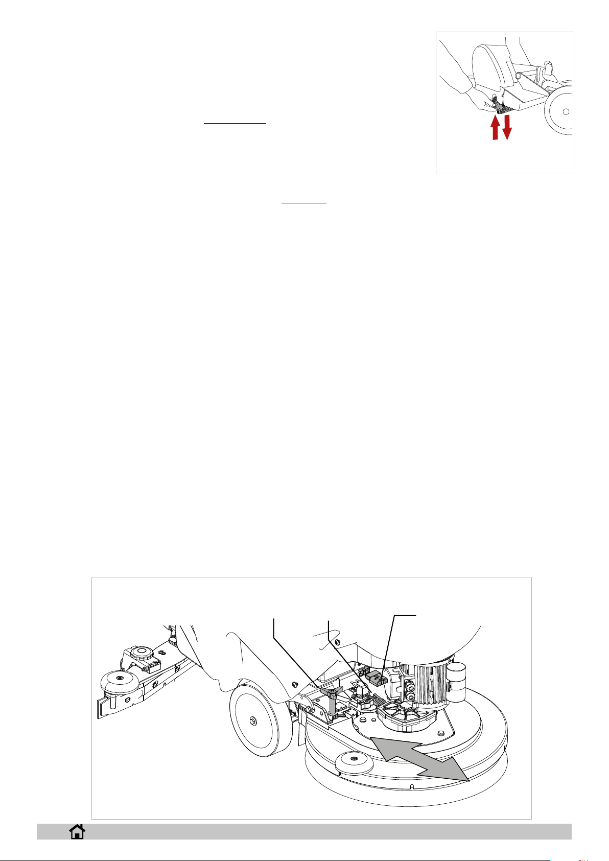
Automatic brush attachment, version “B” (Fig.21):
raise the machine head by pushing the head lift pedal down and to the left, then using the operation selector, select the
Brush control, rest the brush on the oor in front of the machine and centre it with the head. Lower the head by pushing
the head lift pedal down and to the right and activate the drive lever momentarily; the brush will be attached automatically
to the hub on the ange. If the operation is not successful, repeat by pressing the lever again and repeating the centring.
Use of abrasive/microbre disks: t the abrasive/microbre disk on the drive disk and perform the operations described
for tting the brush on the scrubber drier.
Automatic brush attachment, version “BT” (Fig.21):
raise the machine head by pushing the head lift pedal down and to the left, then using the operation selector, select the
Brush control, rest the brush on the oor in front of the machine and centre it with the head. Lower the head by pushing
the head lift pedal down and to the right, turn the selector to the “OFF” position, press the “SET” button once then press
the “+” button, the machine will complete the attachment sequence. Use of abrasive/microbre disks: t the abrasive/
microbre disk on the drive disk and perform the operations described for tting the brush on the scrubber drier.
Automatic brush attachment, version “XP”:
position the brush underneath the head, turn the selector to the “OFF” position, press the “SET” button once then press
the “+” button, the machine will complete the brush attachment sequence.
Automatic brush release, version “B-BT” (Fig.21): raise the machine head by pushing the head lift pedal down and
to the left, turn the selector to the “OFF” position, press the “SET” button once then press the “-” button, the machine will
complete the release sequence.
Automatic brush release, version “XP”:
turn the selector to the “OFF” position, press the “SET” button once then press the “-” button, the machine will complete
the release sequence.
2
4
21
ENGLISH
12
Attaching the brush roller (Fig. 23):
raise the machine head by pushing the head lift pedal down and then to the left, t the rollers in their housing by
rst inserting them on the drive pulley, then pushing them upwards until they click into place.
Releasing the brush roller (Fig. 23):
raise the machine head by pushing the head lift pedal down and then to the left, release the rollers by pulling
them downwards from the side opposite the drive pulley, then extracting them from their housing.
! INFORMATION
Follow the instructions given below to congure the machine’s control software to use the display
language you require:
See the “Technical menu” section.
Lifting and transporting the machine
23
! WARNING
All phases of lifting and moving must be performed in an adequately illuminated environment with the adoption of the safety measures
most appropriate to the situation.
The operator must always use personal protection devices.
Proceed as follows to load the machine onto a means of transport:
► Empty the tanks.
► Remove the batteries.
► Push the machine onto the pallet using a sloping ramp, securing the front wheels and the chassis using the brackets supplied. The machine
must not be raised.
► Lift the pallet (with the machine) using a fork lift truck and load it onto the means of transport.
► Anchor the machine to the means of transport with cables connected to the pallet and to the machine itself.
Quick head change
The scrubber head can be changed as described below.
Removing the head:
► Lower the head (mechanical version) or select “CHANGE HEAD” (electronic version) in the “Technical menu”, pressing the “+” or “-” button
raises or lowers the head, releasing the button stops the actuator. Pressing the “SET” button exits the page and the machine lifts the head.
► Electrically disconnect the head from the machine’s wiring, disconnecting the connector highlighted in the drawing (g. 5-ref. 1) and discon-
necting the motor connector/connectors.
► Open the hook (g. 5, ref. 2).
► Unscrew the two knobs (g. 5-ref. 3).
► Remove the head.
Installing the head:
► Perform the procedure described previously but in the reverse order.
3
ENGLISH
5
2
1
13

PRACTICAL GUIDE FOR THE OPERATOR
! WARNING
Before starting work, wear overalls, ear protectors, non-slip and waterproof shoes, mask to protect the respiratory tract, gloves and all
other personal protection devices necessitated by the work environment.
! WARNING
Never leave the machine unattended or parked with the electronic ignition key inserted.
! INFORMATION
If you are using the machine for the rst time, we recommend trying it out on a large obstacle-free surface rst to acquire the necessary
familiarity.
! WARNING
To avoid damaging the surface of the oor you are cleaning, avoid rotating the brushes with the machine stationary.
! WARNING
Always dilute the detergent according to the manufacturer’s instructions. Do not use sodium hypochlorite (bleach) or other oxidants,
particularly in strong concentrations. Do not use solvents or hydrocarbons. The water and detergent temperature must not exceed the
maximum indicated in the “Technical specications”. They must be free of sand and/or other impurities.
The machine has been designed for use with low-foam biodegradable detergents made specically for scrubber driers.
For a complete and up-to-date list of the detergents and chemicals available, contact the Manufacturer.
Use products suitable for the oor and dirt to be removed only.
Follow the safety regulations on use of detergents given in the section “Safety regulations”.
Preparing the machine for work
Proceed as follows before starting work:
► Check that the display shows the batteries to be fully charged. Recharge if necessary. See the “Battery maintenance and charging” sec-
tion.
► Make sure that the dirty water tank is empty. Empty it if necessary, see “Emptying the dirty water tank”.
► Make sure that the solution tank is full. Fill it if necessary, see “Filling the water/detergent tank”. If the machine is not tted with the “Chem-
Dose” accessory, add detergent to the tank in the required percentage, using the measuring cap.
► Adjust the instrument panel height by unscrewing the adjustment knobs (g. 10-ref. 4).
Controls
► Display (g. 7):
► Displays the maximum speed ramp set (g. 7-ref. 1), version with electric drive.
► The percentage of battery charge (g. 7-ref. 2).
► The machine operating hours (g. 7-ref. 4) standard version, the minutes remaining until the detergent runs out, and alternatively the
sq.m remaining until the detergent runs out on the APC version (ADVANCED PRODUCTIVITY CONTROL).
► The number of litres of detergent in the tank, on the APC version (ADVANCED PRODUCTIVITY CONTROL) (g. 7-ref. 3).
► The alarms (see chapter “Alarms on the display”).
► Indication of the set operating program (g. 7-ref. 5).
► Brush indication, with pressure level (g. 7-ref. 6).
► Water delivery indication, with level (g. 7-ref. 7).
► Suction indication, with speed level (g. 7-ref. 8).
6 7
8
7
1
5
2
4
3
ENGLISH
14

► Electronic key (g. 8-ref. 1): inserting the key enables operation of the machine, remove the
key to completely switch o the machine in an emergency.
► Operation selector (g. 8-ref. 2): turn to select the machine operating program:
► OFF (Fig.9-Ref.3): in this position the electric drive is enabled (where featured), the
speed can be adjusted using the “-” and “+” buttons. Press the “SET” button to manage the following functions:
► pressing the “SET” button once accesses the attach/release brush menu, press-
ing the “-” button enables brush release, pressing the “+” button enables brush
attachment on machines tted with actuator.
► pressing the “SET” button twice accesses the “Technical menu”, to enter the
menu press “-” and “+” together.
► Suction motor (g. 9-ref. 4): in this position the suction motor is activated and the
electric drive is enabled (where featured), the speed can be adjusted using the “-”
and “+” buttons . The suction motor starts by activating the drive lever, in the version
with electric drive the suction motor starts by activating the drive lever after having
lowered the squeegee lift lever (g. 10-ref. 3). Press the “SET” button to manage the
following function:
► pressing the “SET” button once accesses the remote suction menu, pressing
the “+” button starts the suction motor, pressing the “-” button stops the suction
motor, is the suction motor can also be stopped by operating the drive lever.
► Brush (g. 9-ref. 5): in this position the suction motor is activated and the electric
drive is enabled (where featured), the speed can be adjusted using the “-” and “+”
buttons. Press the “SET” button to manage the following functions:
► pressing the “SET” button once accesses the detergent delivery menu, delivery
can be adjusted using the “+” and “-” buttons.
► pressing the “SET” button twice accesses the scrubber head pressure
menu, the pressure can be adjusted using the “+” and “-” buttons on mod-
els equipped with actuator.
► pressing the “SET” button three times accesses the Chem Dose menu,
detergent delivery can be adjusted using the “+” and “-” buttons, on models equipped with Chem Dose.
► Auto (g. 9-ref. 6): in this position all of the machine’s functions are activated,
the head pressure value on models equipped with actuator and the detergent
delivery value are pre-set by the manufacturer, these can be modied in the
“Technical menu” (see chapter “Technical menu”), the electric drive is ena-
bled (where featured), the speed can be adjusted using the “-” and “+” buttons.
Press the “SET” button to manage the following functions:
► pressing the “SET” button once accesses the detergent delivery menu,
delivery can be adjusted using the “+” and “-” buttons.
► pressing the “SET” button twice accesses the scrubber head pressure menu, the pressure can be adjusted using the “+” and “-”
buttons on models equipped with actuator.
► pressing the “SET” button three times accesses the Chem Dose menu, detergent delivery can be adjusted using the “+” and “-”
buttons, on models equipped with Chem Dose.
► Eco (g. 9-ref. 7): in this position all of the machine’s functions are activated, the head pressure value on models equipped with
actuator and the detergent delivery value are pre-set by the manufacturer, these parameters cannot be modied, the electric drive is
enabled (where featured), the speed can be adjusted using the “-” and “+” buttons,
► Drive lever (g. 22): pulling the lever towards the operator engages reverse gear, pushing the lever forwards engages forward gear, to
change speed press the “+” and “-” buttons.
5
4
11
1
38 9
2
10
6
7
22
8
9
ENGLISH
15

► Tank release button (g. 10-ref. 1): releases the tank from the
chassis so it can be rotated backwards.
► Head lift pedal (g. 10-ref. 2): raises and lowers the head on
models without actuator.
► Squeegee lift lever (g. 10-ref. 3): raises and lowers the squee-
gee, enabling or disabling the suction motor on the version with
electric drive.
► Instrument panel height adjustment knobs (g. 10-ref. 4):
unscrew the two knobs to adjust the height of the instrument
panel.
► “SET” button (g. 9-ref. 10): when pressed accesses the ma-
chine operating program submenus, in the “Technical menu”
selects the parameter to be modied and conrms the value en-
tered.
► “+” button (g. 9-ref. 9): increases the value in the machine
operating program submenus, in the “Technical menu” selects
the next parameter or increases the value of the selected pa-
rameter.
► Button “-” (g. 9-ref. 8): decreases the value in the machine oper-
ating program submenus, in the “Technical menu” selects the pre-
vious parameter or decreases the value of the selected parameter.
1
4
3
2
10
Working
► Insert the electronic key.
► Using the operation selector, select the scrubbing program.
► Activate the drive lever, lower the squeegee and start working.
► In the machines without electric drive, turning the knob (g. 11-ref. 1)
corrects any tendency to deviate from a straight line.
1
11
Some useful tips to get the most from your
scrubber drier
In the event of particularly stubborn dirt on the oor, washing and drying can be performed in two separate operations.
Prewashing with brushes or pads:
► Select the Brush operating program.
► Activate the drive lever, start working.
► If necessary, adjust the ow of detergent delivered to the brush; the outlet ow must be metered in relation to the required travel speed; the
slower the machine travels, the less detergent must be delivered.
► Persist when washing particularly dirty points to give the detergent time to perform its chemical action detaching and suspending the dirt and
the brushes time to exert an eective mechanical action.
Drying:
► Select the Suction operating program, lower the squeegee.
► Activate the drive lever, start working.
► Pass over the same area washed previously. The result is equivalent to in-depth washing and subsequent ordinary maintenance will take
less time.
Emptying the collection tank
If the tank is full, the display shows the corresponding alarm, see the chapter “Display alarms”; after a few seconds, the suction motor shuts down,
then stop the machine and empty the tank following the instructions shown below. To resume
work, turn the operation selector to the OFF position (reset errors):
► Switch o all the machine’s functions.
► Take the machine to the disposal area.
► Unhook the hose from the clip.
► Empty the tank using the hose (g. 12, ref. 1), at the end rinse the tank with clean water.
12
ENGLISH
1
16

Emptying the water/detergent tank
To empty the tank, follow the instructions shown below:
► Switch o all the machine’s functions.
► Take the machine to the disposal area.
► Stop the machine.
► Empty the tank by unscrewing the lter assembly (g. 13-ref. 1).
Emptying the roller head bin
► Remove the sweeper collection bin (Fig. 24), dispose of the contents and rinse out the bin
with clean water.
Filling the water/detergent tank
Fill the tank through the opening provided (g. 14, Ref. 1). The machine is equipped with a graduated
measuring cap that can be used to dilute the detergent inside the tank. If the tank is empty, the display
shows the corresponding alarm, see the chapter “Display alarms”; to resume work, turn the opera-
tion selector to the OFF position (reset errors).
Filling the Chem-Dose tank (accessory)
Open the dirty water tank lid, ll the container highlighted in the drawing (g. 14-ref. 2) with detergent.
Finishing work
! INFORMATION
Empty the dirty water tank and recharge the batteries
After having nished work, remove the electronic key.
Moving the machine when not in operation
Proceed as follows to move the machine:
► Raise the squeegee.
► Raise the head.
► Move the operating program selector to O.
► Versions with mechanical drive: push or pull.
► Version with electric drive: activate the drive lever.
13
FILTER
1
2
1
14
ENGLISH
24
17

MAINTENANCE INSTRUCTIONS
! DANGER
Never perform any maintenance operations without rst disconnecting the bat-
teries.
Maintenance on the electrical circuit and all other operations not explicitly described in this manual must be performed by specialised personnel only, in
compliance with current safety legislation and as described in the maintenance
manual.
! DANGER
Before lifting/rotating the tank to access the compartment, its contents must
rst be emptied, then insert the safety bracket in position to prevent the tank
from accidentally closing again, see chapter “SAFETY INFORMATION”.
Maintenance - General rules
Performing regular maintenance according to the Manufacturer’s instructions improves performance and extends the working life of the machine.
When cleaning the machine, observe the following precautions:
► Avoid using pressure washers. Water could penetrate the electrical compart-
ment or motors leading to damage or short circuits.
► Do not use steam to avoid the heat warping plastic parts.
► Do not use solvents or hydrocarbon based products. These can damage the
cowling and rubber components.
Cleaning the suction motor air lter
Open the dirty water tank lid by releasing the closing level, then remove the lter (g.
15-ref. 1), wash it under running water or using the same detergent as used on the
machine, then dry and reposition the lter. Lift the tank, remove the lter (g. 16-ref.
1), wash it under running water or using the same detergent as used on the machine,
then dry and reposition the lter.
Cleaning the debris container
Open the dirty water tank lid, then empty the debris accumulated in the container (g.
15-ref. 2); if needing to wash the container, remove it by lifting it out and then clean it.
Cleaning the dirty water tank oat
Open the dirty water tank lid, then remove the debris container by lifting it out (g. 15ref. 2), turn the oat protector (g. 15-ref. 3) and then clean the oat; make sure that the
oat slides freely on its pin.
Cleaning the water/detergent tank lter
To clean the lter, proceed as follows:
► Unscrew the lter cap (g. 17-ref. 1), remove the lter/hose union (g. 17-ref.
2, then wash under running water or using the same detergent as used on the
machine.
► Replace the lter in its housing, making sure it is correctly positioned and
screw the cover back on.
15
2
3
1
16
1
ENGLISH
17
FILTER
1-2
18

Fuses: replacing
! WARNING
Never use a fuse with a higher amperage than specied.
The fuses can only be replaced by an IP Cleaning service centre or by technical personnel authorised by IP Cleaning.
Lift the tank, disconnect the battery wiring connector from the electrical system or unplug
the power cable, remove the cover (Fig. 18-Ref. 1) to access the fuses.
Battery maintenance and charging
! INFORMATION
Before charging the batteries, remove the electronic key from the instrument pan-
el.
! DANGER
Do not check the batteries by sparking.
The batteries (WET) give o ammable fumes. Put out all res and hot embers
before checking or topping up the battery level.
! DANGER
Perform the operations described below in a ventilated area.
! WARNING
When charging the batteries, the tank must be lifted and kept open, to allow correct ventilation of the battery compartment.
! WARNING
In the case of gel batteries, use a specic charger for gel batteries only.
! WARNING
To avoid permanent damage to the batteries, do not run them down completely.
! WARNING
Charge the batteries as instructed in the battery charger manual.
Disconnect the connectors at the end of charging.
18
1
“STANDALONE” battery charger, electrical connection to the machine:
► Turn the machine o.
► Plug the battery charger connector into the socket on the machine as highlighted (g. 19-ref. 1).
► Start the recharge cycle.
► Disconnect the connectors at the end of charging.
“ONBOARD” battery charger:
► Turn the machine o.
► Unplug the battery charger from the socket (g. 19-ref. 2).
► Plug into the mains socket.
► Start the recharge cycle.
► The display will show when the recharge cycle ends, see “Display alarms”
► At end of the recharge cycle, unplug the cable from the power socket.
1 2
19
24V
BATTERY CHARGER STAND ALONE
ENGLISH
BATTERY CHARGER ON BOARD
19

Replacing the squeegee blades
► Lower the squeegee.
► Remove the suction hose from the squeegee
► Lift the squeegee fastening levers.
► Remove the squeegee from the slots on the support.
► Open the hook (g. 20, ref. 1).
► Push the two blade pressing devices (g. 20, ref. 2) outwards, then remove
them.
► Remove the blade.
► Reuse the same blade by reversing the edge in contact with the oor until all
four edges are worn out, or replace with a new blade, tting it onto the screws
on the body of the squeegee.
► Reposition the two blade pressing devices by centering the wider part of the
slots on the squeegee body fastening pins, then push the blade pressing devic-
es inwards.
► Close the hook again.
► Replace the squeegee on its support, following the instructions described previously.
1
2
Periodic checks
CHECKS DAILY OPERATIONS WEEKLY OPERATIONS
EMPTY AND WASH THE DIRTY WATER TANK X
CLEAN THE SQUEEGEE BLADES AND CHECK THEM FOR WEAR X
CHECK THAT THE SUCTION HOLE IN THE SQUEEGEE IS NOT BLOCKED X
RECHARGE THE BATTERIES X
CLEAN THE DIRTY WATER TANK FLOAT X
CLEAN THE SUCTION MOTOR AIR FILTER X
CLEAN THE WATER/DETERGENT TANK FILTER X
CLEAN THE SUCTION MOTOR HOSE X
CLEAN THE DIRTY WATER TANK AND THE SOLUTION TANK X
CHECK THE BATTERY ELECTROLYTE LEVEL X
HAVE THE ELECTRICAL CIRCUIT CHECKED BY QUALIFIED IP CLEANING PERSONNEL X
SIX MONTHLY
OPERATIONS
20
PERIODS OF INACTIVITY
If the machine is not used for some time, for example, on display in a showroom or stored in the warehouse for a period or more than one month, the
following operations are required:
► Recharge completely the batteries. During long periods of inactivity, you should charge the batteries regularly (at least once every two
months) to keep them constantly at maximum charge.
► Disconnect the batteries from the machine.
► Unplug the battery charger (if present) from the mains power supply.
► Remove the squeegee and brushes (or abrasive disks), wash them and put them away in a dry place (preferably in a bag or wrapped in
plastic lm) away from dust.
► Make sure the tanks are completely empty and perfectly clean.
! WARNING
If the batteries are not recharged regularly as described above, they may be irrevocably damaged.
The manufacturer is not liable for any malfunctions resulting from neglect, improper and/or incorrect use.
! WARNING
When the batteries are at, make sure they are not left for an extended time without charging to avoid shortening battery life.
Check battery charge at least once a week.
ENGLISH
20

TROUBLESHOOTING
B = 24 Vdc battery version
BT = 24 Vdc battery version with electric drive
C = 100-115-230 Vac cable version
PROBLEM CAUSE REMEDY
The machine does not work The batteries are disconnected (B-BT) Connect the batteries to the machine
The batteries are at (B-BT) Recharge the batteries
Blown fuse (B, BT-C) Replace
Electronic key not inserted (B-BT-C) Engage.
Power cable unplugged from the power socket (C) [C]= plug into the mains socket
The brushes do not turn The dirty water tank is full (B, BT-C) Empty the dirty water tank
Blown fuse (B, BT-C) Replace
Relay damaged (B-BT-C) Replace
The batteries are at (B-BT) Recharge the batteries
Motor damaged (B, BT-C) Replace
The machine does not clean uniformly The brush or abrasive disks are worn(B-BT-C) Replace
No solution comes out of the detergent tank Solenoid valve damaged (B-BT-C) Replace
Solenoid valve dirty (B-BT-C) Check
The detergent tank is empty (B-BT-C) Top up
The hose delivering detergent to the brush is blocked (B-BT-C) Unblock
Blown fuse (B, BT C) Replace
Detergent ow does not stop Solenoid valve damaged (B-BT-C) Replace
Solenoid valve wiring damaged (B-BT-C) Check
The suction motor does not start The dirty water tank is full (B, BT-C) Empty the dirty water tank
Blown fuse (B, BT-C) Replace
Squeegee lever raised (BT) Lower
The batteries are at (B-BT) Recharge the batteries
Motor damaged (B, BT-C) Replace
The squeegee does not clean or has poor suction The edge of the rubber blades in contact with the oor is worn Replace the blades
Blockage or damage in the squeegee (B-BT-C) Check
The dirty water tank oat is activated or is blocked by dirt, or is
faulty (B-BT-C)
Blockage in the suction hose (B, BT C) Check
The suction hose is not connected to the squeegee or is
damaged (B-BT-C)
The machine does not move The batteries are at (B-BT) Recharge the batteries
Damaged motor (BT) Replace
The batteries do not provide the normal working time The battery poles and charging terminals are dirty and oxidised
(B-BT)
The battery charger does not work or is not suitable (B-BT) Check
Empty the dirty water tank, check the oat
Check
Clean and grease the poles and terminals, charge the batteries
ENGLISH
21

DISPLAY ALARMS
Alarm Possible cause What to do
BRUSH PROTECTOR The brush motor has
DRIVE PROTECTOR The drive wheel has
WATER RESERVE Solution tank almost empty.
NO WATER Solution tank empty.
DIRTY WATER THANK. Dirty water tank full.
CHEMICAL FINISHED Chem-Dose tank empty.
FUNCTION BOARD NOT
DETECTED
BATTERY RESERVE Battery voltage less than
CALL SERVICE The set number of hours for
BATTERY CHARGING The on-board battery
CHARGING COMPLETE The on-board battery charger
O.C. BRUSH Excessive motor eort.
DRIVE BOARD
TEMPERATURE
ACCELERATOR FAULT Faulty potentiometer
overheated.
Faulty thermal protector
contact on the motors.
Faulty connection.
overheated.
Faulty thermal protector
contact on the motor.
Faulty connection.
Stuck sensor.
Faulty sensor or connection.
Stuck sensor.
Faulty sensor or connection.
Stuck sensor.
Faulty sensor or connection.
Stuck sensor.
Faulty sensor or connection.
Communication with
functions board interrupted.
Faulty auxiliary boards.
: 21.9 V GEL/AGM - 21 V
ACID.
Flat batteries.
scheduled service have been
reached/exceeded.
charger is operating, all the
machine’s functions are
disabled.
is operating, the charge is
complete, all the machine’s
functions are disabled.
Faulty functions board.
Brush motor faulty
Excessive vehicle eort.
Faulty drive board.
Electric brake engaged.
connections.
Faulty potentiometer.
Wait for the brush motors to
cool down.
Replace the brush motor.
Check the connection.
Wait for the drive wheel to
cool down.
Replace the drive wheel.
Check the connection.
Fill the solution tank.
Clean the level sensor.
Replace the level sensor.
Check the connection.
Fill the solution tank.
Clean the level sensor.
Replace the level sensor.
Check the connection.
To resume work, turn the
operation selector to the OFF
position (reset errors).
Empty the dirty water tank.
Clean the level sensor.
Replace the level sensor.
Check the connection.
To resume work, turn the
operation selector to the OFF
position (reset errors).
Fill the Chem-Dose tank.
Clean the level sensor.
Replace the level sensor.
Check the connection.
Check the connection
between the boards.
Check the auxiliary boards.
Recharge the batteries.
Replace the batteries.
Call a service centre to
arrange servicing.
Disconnect the battery
charger.
Disconnect the battery
charger.
Check motor load.
Replace functions board.
Replace the brush motor.
Cool or heat the board.
Do not overwork the machine
on long ramps.
Replace the drive control
board.
Check the electric brake.
Check the connection.
Replace the potentiometer.
BATTERY FLAT Battery voltage less than
TAG FAULT Faulty key.
RFID FAULT Faulty key.
SUCTION MOTOR
TEMPERATURE
BRUSH TEMPERATURE Excessive motor eort.
O.C. SUCTION MOTOR Excessive motor eort.
O.C. DRIVE Excessive vehicle eort.
UPDATE FW MAIN BOARD Software update. Do not remove the key
UPDATE FW SERVICE
BOARD
FLASHING LIGHT FAULT Faulty wiring.
SOLENOID VALVE FAULT Faulty wiring.
PUMP FAULT Faulty wiring.
BRUSH FUSE Excessive motor eort.
SUCTION MOTOR FUSE Excessive motor eort.
21.4 V - GEL / 20.5 V - ACID.
Flat or degraded batteries.
Faulty instrument panel
antenna board
Faulty instrument panel
antenna board
Excessive motor eort.
Faulty functions board.
Faulty suction motor.
Faulty functions board.
Faulty motor.
Faulty functions board.
Faulty suction motor.
Faulty drive board.
Electric brake engaged.
Software update. Do not remove the key
Faulty ashing light.
The ashing light is broken.
The ashing light has been
enabled in the Technical
menu but it is not tted on the
machine.
Faulty solenoid valve.
Solenoid valve broken.
Faulty pump.
The pump is broken.
The pump has been enabled
in the Technical menu but it
is not tted on the machine.
Faulty brush motor contactor.
Motor fuse blown.
Faulty brush motor relay.
Motor fuse blown.
Recharge the batteries.
Replace the batteries.
Replace the key.
Replace the instrument
panel antenna board-reed.
Check the wiring.
Replace the key.
Replace the instrument
panel antenna board-reed.
Check the wiring.
Check the suction motor.
Replace functions board.
Replace the suction motor.
Check the motor.
Replace functions board.
Replace the motor.
Check the suction motor.
Replace functions board.
Replace the suction motor.
Check the motor.
Replace the drive board.
Check the electric brake.
during the update.
during the update.
Check the wiring.
Check the ashing light.
Replace the ashing light.
Correct the settings in the
Technical Menu.
Check the wiring.
Check the solenoid valve.
Replace the solenoid valve.
Check the wiring.
Check the pump.
Replace the pump.
Correct the settings in the
Technical Menu.
Check the motor.
Replace the contactor.
Replace the fuse.
Check the motor.
Replace the relay.
Replace the fuse.
DRIVE BOARD U.V. Battery voltage less than
RELAY FAULT Faulty relay.
ELECTRIC BRAKE FAULT Faulty wiring.
HPD Drive lever pressed when
18.3 V GEL/AGM - 18 V
ACID.
Flat or degraded batteries.
Faulty relay connection.
Faulty electric brake.
The electric brake has been
enabled in the Technical
menu but is not tted on the
machine.
starting.
Drive lever potentiometer not
adjusted.
Charge or replace the
batteries.
Replace the relay.
Check relay connections.
Check the wiring.
Check / replace the electric
brake.
Correct the settings in the
Technical Menu.
Release the drive lever when
starting the machine.
Check potentiometer
adjustment.
ENGLISH
22

TECHNICAL MENU CT51 - 71
Access the menu by turning the operation selector to OFF and pressing “SET” twice, then press the “+” and “-” buttons together.
The “+” button increases the selected parameter or the variable relating to the selected parameter.
The “-” button decreases the selected parameter or the variable relating to the selected parameter.
The “SET” button selects the parameter to be set and conrms the entered variable.
B BT-XP
WORK AREA
LANGUAGE
AUTO PROGRAM
IT, GB, ES.......
DETERGENT FLOW-
RATE
AUTO PROGRAM
0/5/3WATER FLOW-RATE
OFF - 0.2 - 0.3 - ...7%
(OFF)
WORK AREA
LANGUAGE
IT, GB, ES.......
BRUSH PRESSURE
(version with actuator
only)
WATER FLOW-RATE
SPEED REDUCTION
DETERGENT FLOW-
RATE
BRUSH PWM
SUCTION PWM
1/5/2
1/5/3
0.....100% (100%)
OFF - 0.2 - 0.3 - ...7%
(OFF)
10.....100% (100%)
70.....100% (100%)
POWER OFF
BATTERY TYPE
SERVICE
EXIT
BRUSH STOP DEL.
SUCTION STOP DEL.
EXIT
GEL-AGM / LEAD-ACID
(GEL-AGM)
PASSWORD
OFF- 0 -15 sec (2)
OFF- 0 -15 sec (7)
EXIT
EXIT
POWER OFF BRUSH STOP DELAY
SUCTION STOP DELAY
EXIT
CHANGE HEAD
BATTERY TYPE
MAX SPEED
MIN SPEED
SERVICE
“+” ; “-”
GEL-AGM - ACID (GEL-AGM)
40 - 100% (70%)
0 - 40% (10%)
10 - 100% (50%)REVERSE SPEED
PASSWORD
EXIT
OFF - 1 - 2 - ...30
seconds (3)
OFF - 1 - 2 - ...30
seconds (3)
EXIT
WORK AREA
WORK AREA
ENGLISH
EXIT
23

IP Cleaning S.p.A.
Viale Treviso 63
30026 Summaga di Portogruaro
Venezia (Italy)
T: +39 0421 205511
F: +39 0421 204227
E: www.ipcworldwide.com
W: info@ipcworldwide.com
PLDC02194_8
 Loading...