


USER’S
MANUAL
B
A
-0951
Intel® Xeon
®
E3 v3 with Intel
®
C226 ATX Motherboard
features VGA/2 LAN/DP/6COM
BA-0951
M2

BA-0951 Intel® Xeon
®
E3 v3
with Intel® C226
ATX Motherboard
COPYRIGHT NOTICE & TRADEMARK
All trademarks and registered trademarks mentioned herein are the property of their
respective owners.
This manual is copyrighted in Aug. 2013 (Revised edition: Sep. 2013). You may
not reproduce or transmit in any form or by any means, electronic, or mechanical,
including photocopying and recording.
DISCLAIMER
This operation manual is meant to assist both Embedded Computer manufacturers
and end users in installing and setting up the system. The information contained in
this document is subject to change without any notice.
CE NOTICE
This is a class A product. In a domestic environment this product may cause radio
interference in which case the user may be required to take adequate measures.

FCC NOTICE
This equipment has been tested and found to comply with the limits for a Class A
digital device, pursuant to part 15 of the FCC Rules. These limits are designed to
provide reasonable protection against harmful interference when the equipment is
operated in a commercial environment. This equipment generates, uses, and can
radiate radio frequency energy and, if not installed and used in accordance with
the instruction manual, may cause harmful interference to radio communications.
Operation of this equipment in a residential area is likely to cause harmful
interference in which case the user will be required to correct the interference at
his own expense.
You are cautioned that any change or modifications to the equipment not
expressly approve by the party responsible for compliance could void your
authority to operate such equipment.
CAUTION! Danger of explosion if battery is incorrectly replaced. Replace only with the
same or equivalent type recommended by the manufacturer. Dispose of used batteries
according to the manufacturer’s instructions.

Contents
TABLE OF CONTENTS
CHAPTER 1 INTRODUCTION
1-1 About This Manual…............................................................ 1-2
1-2 System Specification….......................................................... 1-3
1-3 Safety Precautions…............................................................. 1-5
CHAPTER 2 HARDWARE CONFIGURATION
2-1 Jumper & Connector Quick Reference Table….................... 2-2
2-2 Component Locations….…................................................... 2-3
2-3 How to Set Jumpers…........................................................... 2-4
2-4 COM Port & Connector…...……………….......................... 2-6
2-5 COM Port RI & Voltage Selection………………………… 2-8
2-6 RS-232/422/485 (COM2) Selection……………………….. 2-9
2-7 COM2 Auto Detect Selection……………………………… 2-9
2-8 BIOS Recovery Mode Selection…………………………… 2-10
2-9 Clear CMOS Data Selection……………………………….. 2-10
2-10 VGA Port…………………………………………………... 2-11
2-11 Mini-DIN & USB Port..……………………………………. 2-12
2-12 LAN & USB Ports…………………………………………. 2-13
2-13 USB Connector…………………………………………….. 2-15
2-14 TPM Connector…………………………………………….. 2-16
2-15 Front Panel Connector & Selection………………………... 2-16
2-16 ATX Power Connector……………………………………... 2-18
2-17 SATA Connector…………………………………………… 2-19
2-18 CPU Fan Connector………………………………………... 2-20
2-19 System Fan Connector……………………………………... 2-21
2-20 Printer Port…………………………………………………. 2-22
2-21 Display Port Connector…………………………………….. 2-23
2-22 Digital Input/Output Connector……………………………. 2-24
2-23 Audio Port & Connector…………………………………… 2-25

Contents
CHAPTER 3 SOFTWARE UTILITIES
3-1 Introduction……………..........................................…......... 3-2
3-2 Intel® Chipset Software Installation Utility……..……..…... 3-4
3-3 Intel® Rapid Storage Technology Utility…………………... 3-5
3-4 Intel® USB3.0 eXtensible Host Controller Utility…………. 3-6
3-5 Intel® Management Engine Components Utillity…………... 3-7
3-6 VGA Driver Utility………………………………….……... 3-8
3-7 LAN Driver Utility……...........................................…......... 3-9
3-8 Sound Driver Utility……………………………………….. 3-10
CHAPTER 4 BIOS SETUP
4-1 Introduction…....................................................................... 4-2
4-2 Entering Setup…................................................................... 4-4
4-3 Main…………...................................................................... 4-6
4-4 Advanced…........................................................................... 4-8
4-5 Chipset…............................................................................... 4-38
4-6 Boot……............................................................................... 4-52
4-7 Security….............................................................................. 4-54
4-8 Save & Exit…....................................................................... 4-56
4-9 Event Logs…………………………………………………. 4-57
APPENDIX A EXPANSION BUS
Mini-PCIe Bus……………………………………………………... A-2
PCIe Bus…………………………………....................................... A-3
APPENDIX B TECHNICAL SUMMARY
Block Diagram….............................................................................. B-2
Interrupt Map…................................................................................ B-3
DMA Channels Map…..................................................................... B-8
I/O Map…........................................................................................ B-9
Memory Map….…………………………………………………… B-12
Watchdog Timer Configuration….………………...……………… B-14
Flash BIOS Update…...............................................….................... B-17

Page:1-1
INTRODUCTION
This chapter gives you the information for BA-0951. It also outlines
the system specifications.
Sections included:
About This Manual
System Specifications
Safety Precautions
Experienced users can jump to chapter 2 on page 2-1
for a quick start.
CHAPTER
1

Chapter 1 Introduction
BA-0951 USER′S MANUAL
Page: 1-2
1-1. ABOUT THIS MANUAL
Thank you for purchasing our BA-0951 Intel® Xeon® E3 v3 with Intel® C226 ATX
Motherboard enhanced with VGA/2LAN/DP, which is fully PC/AT compatible.
The BA-0951 provides faster processing speed, greater expandability and can
handle more tasks than before. This manual is designed to assist you how to install
and set up the system. It contains four chapters. The user can apply this manual for
configuration according to the following chapters:
Chapter 1 Introduction
This chapter introduces you to the background of this manual, and the
specifications for this system. The final page of this chapter will indicate how to
avoid damaging this board.
Chapter 2 Hardware Configuration
This chapter outlines the component locations and their functions. In the end of
this chapter, you will learn how to set jumper and how to configure this card to
meet your own needs.
Chapter 3 Software Utilities
This chapter contains helpful information for proper installations of the VGA
utility, LAN utility, Sound utility, and Flash BIOS Update. It also describes the
Watchdog-timer configuration.
Chapter 4 BIOS Setup
This chapter indicates you how to set up the BIOS configurations.
Appendix A Expansion Bus
This appendix introduces you the expansion bus for PCIe connectors.
Appendix B Technical Summary
This appendix gives you the information about the Technical maps.

Chapter 1 Introduction
BA-0951 USER′S MANUAL
Page: 1-3
1-2. SYSTEM SPECIFICATIONS
System
CPU Intel® Xeon® Processor (LGA1150)
E3-1275 v3 (84W)
E3-1225 v3 (84W)
E3-1268L v3 (45W)
OS Support Windows 7, 8, Server 2008 R2
Chipset Intel® C226
Memory 4 x DIMM (204 pins), DDR3/DDR3L 1333/1600 MHz, up
to 32GB, support ECC/non-ECC
BIOS AMI
Watchdog 1~255 seconds
Power Supply ATX 24 + 4 power supply
Dimension 244 x 305 mm (9.6” x 12”)
Certificate CE/FCC
I/O Ports
Serial Port 6 ports:
COM1: D-sub
COM2~COM6: Box headers on board
(COM1/3/4/5/6 for RS-232, COM2 for RS-232/422/485;
COM3/4 supports 5V/12V)
USB Port 4 x external USB 3.0, stacked with LAN
8 x USB 2.0 (2 are external & stacked with PS/2, 6 are
internal pin-headers.)
Parallel Port 1 x printer port
SATA Interface 6 x SATA III connector
VGA 1 x VGA
LAN 2 ports, support Wake-on-LAN
Intel® I217-LM/V, compatible with Intel® 82579
Intel® I210-AT
Audio High Definition audio codec: Realtek ALC888S-VD2-GR
Line-in/Line/out/MIC audio jack
Chapter 1 Introduction
BA-0951 USER′S MANUAL
Page: 1-4
Keyboard/Mouse 1 x PS/2
Expansion Bus 2 x PCIe (8x) 3.0
4 x PCIe (1x) 2.0
1 x Mini-PCIe (without mSATA)
Display
Graphics Built-in processor to share the system memory.
1 x CRT
3 x Display connectors (Protech standard DP/eDP
connectors)
*Discrete graphic card is necessary for display if the chosen CPU doesn’t support
integrated graphics.
Environment
Operation Temp. 0 ~ 60°C (32 ~ 140°F)
Storage Temp. -40 ~ 85°C (-40 ~ 185°F)
Humidity Operation: 5~90% (non-condensing)

Chapter 1 Introduction
BA-0951 USER′S MANUAL
Page: 1-5
1-3. SAFETY PRECAUTIONS
Follow the messages below to avoid your systems from damage:
1. Keep your system away from static electricity on all occasions.
2. Prevent electric shock. Don‘t touch any components of this card when the card is
power-on. Always disconnect power when the system is not in use.
3. Disconnect power when you change any hardware devices.
For instance, when you connect a jumper or install any cards, a surge of power
may damage the electronic components or the whole system.

Page 2-1
HARDWARE
CONFIGURATION
** QUICK START **
CHAPTER
2
Helpful information describes the jumper & connector settings, and
component locations.
Sections included:
Jumper & Connector Quick Reference Table
Component Locations
Configuration and Jumper settings
Connector’s Pin Assignments

Chapter 2 Hardware Configuration
BA-0951 USER′S MANUAL
Page: 2-2
2-1. JUMPER & CONNECTOR QUICK REFERENCE TABLE
JUMPER/CONNECTOR NAME
COM Port & Connector COM1, COM2, COM3, COM4,
COM5, COM6
COM Port RI & Voltage Selection JP_COM3, JP_COM4
RS-232/422/485 (COM2) Selection JP8
COM2 Auto Detect Selection JP7
BIOS Recovery Mode Selection JP1
Clear CMOS Data Selection JP4
VGA Port VGA1
Mini-DIN & USB Port JP2USB1
LAN & USB Port LAN1_USB1, LAN2_USB1
USB Connector USB6_1, USB8_1, USB10_1
TPM Connector JLPC1
Front Panel Connector & Selection FP1
ATX Power Connector ATX_PWR1, ATX_PWR2
SATA Connector SATA1, SATA2, SATA3, SATA4,
SATA5, SATA6,
CPU Fan Connector CPU_FAN1
System Fan Connector SYS_FAN1, SYS_FAN2, SYS_FAN3,
SYS_FAN4
Printer Port LPT1
Display Port Connector JDP1, JDP2, JDP3
Digital Input/Output Connector DIO1
Audio Port & Connector AUDIO1, AUDIO2
Chapter 2 Hardware Configuration
BA-0951 USER′S MANUAL
Page: 2-3
2-2. COMPONENT LOCATIONS
AUDIO1
SIO
LAN2_USB2
LAN1_USB1
JPS2USB1
LPT1
ATX_PWR2
CPU_FAN1
SYS_FAN2
ATX_PWR1
SATA5SATA3SATA1
SATA6
JP1
SATA4SATA2
FP1
SP1
JP9
DIO1
COM6
COM5
COM4
COM3
COM2
JP7
JDP3 JDP2 JDP1
PCI_E6 PCI_E5 PCI_E4 PCI_E3
PCI_E2 PCI_E1
JP8
SYS_FAN4
JP_COM4
JP_COM3
USB10_1
USB8_1
M_PCIE1
USB6_1
JLPC1
SYS_FAN1
SYS_FAN3
AUDIO2
DIMM1
DIMM2
DIMM3
DIMM4
COM1
VGA1
1
JP6
127
8
Intel
®
C226
REMOVE
Intel® Xeon
®
E3 v3
(LGA1150)
20219
1
20219
1
20219
1
1
121
120
240
1
121
120
240
1
121
120
240
1
121
120
240
1
4
1
4
1
4
1
4
14
9101
2
2
1
10
9
1
2
3
4
1
125
6
6 1
10 5
6 1
10 5
6 1
10 5
6 1
10 5
6 1
10 5
1
1324
12
17
17 17 17
17 17
12
21
21
11
2019
12
1 2
9 10
9 1 0
21
21
9 10
21
9 1 0
21
11
12151617
18
51
52
Battery
125
6
JP3JP4
11
BA-0951 Front Connector, Jumper and Component locations
Chapter 2 Hardware Configuration
BA-0951 USER′S MANUAL
Page: 2-4
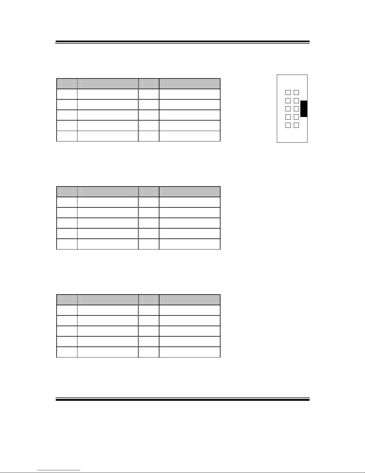
2-3. HOW TO SET THE JUMPERS
You can configure your board by setting jumpers. Jumper is consists of two or three metal
pins with a plastic base mounted on the card, and by using a small plastic "cap", Also
known as the jumper cap (with a metal contact inside), you are able to connect the pins.
So you can set-up your hardware configuration by "open" or "close" pins.
The jumper can be combined into sets that called jumper blocks. When the jumpers are all
in the block, you have to put them together to set up the hardware configuration. The figure
below shows how this looks like.
JUMPERS AND CAPS
If a jumper has three pins (for examples, labelled PIN1, PIN2, and PIN3), You can connect
PIN1 & PIN2 to create one setting by shorting. You can either connect PIN2 & PIN3 to
create another setting. The same jumper diagrams are applied all through this manual. The
figure below shows what the manual diagrams look and what they represent.

Chapter 2 Hardware Configuration
BA-0951 USER′S MANUAL
Page: 2-5
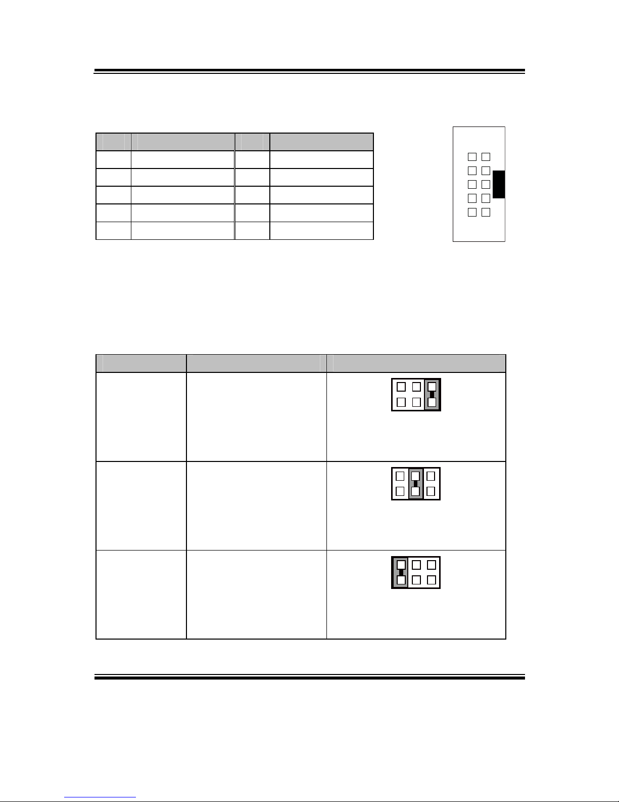
JUMPER DIAGRAMS
2 pin Jumper
looks like this
Jumper Cap
looks like this
3 pin Jumper
looks like this
Jumper Block
looks like this
JUMPER SETTINGS
Looks like this
3 pin Jumper
2-3 pin close(enabled)
Looks like this
Jumper Block
1-2 pin close(enabled)
2 pin Jumper close(enabled)
1
1
1
2
1 2
1
1
Looks like this
Chapter 2 Hardware Configuration
BA-0951 USER′S MANUAL
Page: 2-6
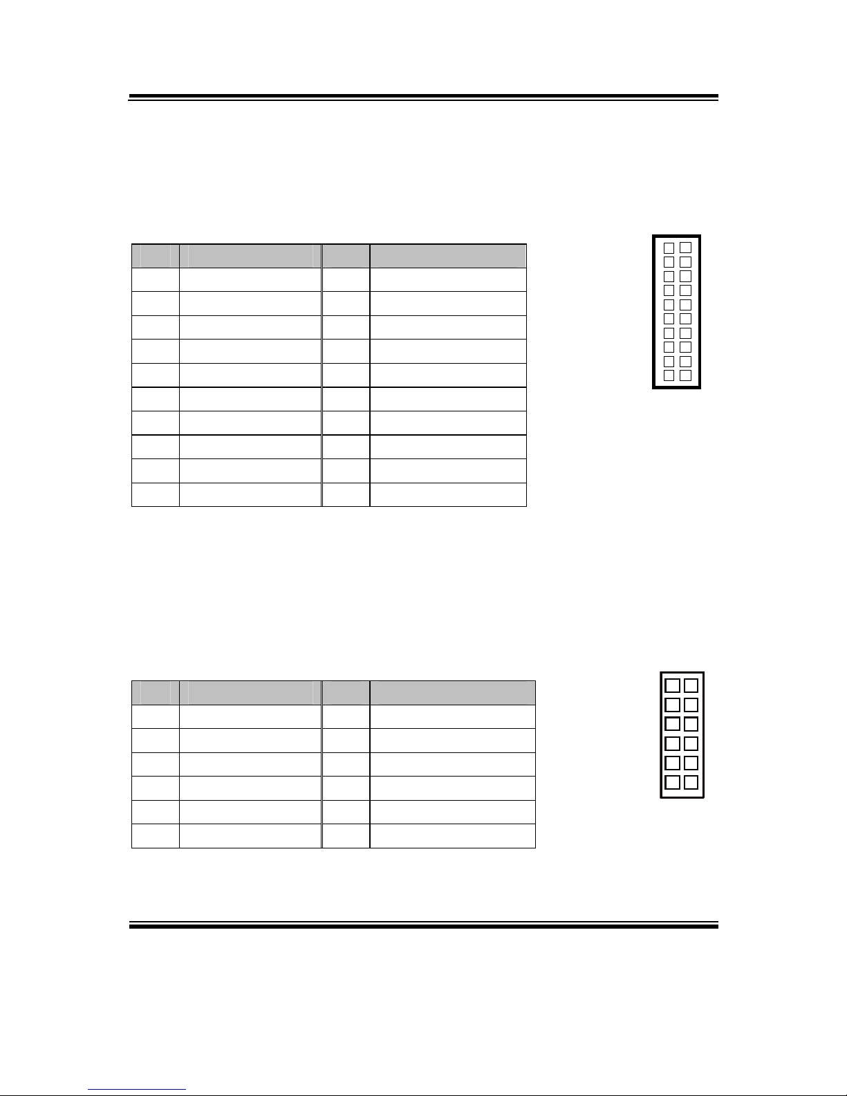
2-4. COM PORT & CONNECTOR
COM1: COM1 Port, fixed as RS-232
The pin assignments are as follows:
PIN ASSIGNMENT PIN ASSIGNMENT
1 COM1_DCD# 6 COM1_DSR#
2 COM1_RX 7 COM1_RTS#
3 COM1_TX 8 COM1_CTS#
4 COM1_DTR# 9 COM1_RI#
5 GND
COM2: COM2 Connector, selectable as RS-232/422/485
The pin assignments are as follows:
ASSIGNMENT
PIN
RS-232 RS-422 RS-485
1 COM2_DCD# TX- 485-
2 COM2_RX TX+ 485+
3 COM2_TX RX+ X
4 COM2_DTR# RX- X
5 GND GND GND
6 COM2_DSR# X X
7 COM2_RTS# X X
8 COM2_CTS# X X
9 COM2_RI# X X
10 NC NC NC
5
1
96
COM1
6 1
10 5
COM2
Chapter 2 Hardware Configuration
BA-0951 USER′S MANUAL
Page: 2-7
COM3: COM3 Connector, fixed as RS-232
The pin assignments are as follows:
PIN ASSIGNMENT PIN ASSIGNMENT
1 COM3_DCD# 6 COM3_DSR#
2 COM3_RX 7 COM3_RTS#
3 COM3_TX 8 COM3_CTS#
4 COM3_DTR# 9 COM3_RI#
5 GND 10 NC
COM4: COM4 Connector, fixed as RS-232
The pin assignments are as follows:
PIN ASSIGNMENT PIN ASSIGNMENT
1 COM4_DCD# 6 COM4_DSR#
2 COM4_RX 7 COM4_RTS#
3 COM4_TX 8 COM4_CTS#
4 COM4_DTR# 9 COM4_RI#
5 GND 10 NC
COM5: COM5 Connector, fixed as RS-232
The pin assignments are as follows:
PIN ASSIGNMENT PIN ASSIGNMENT
1 COM5_DCD# 6 COM5_DSR#
2 COM5_RX 7 COM5_RTS#
3 COM5_TX 8 COM5_CTS#
4 COM5_DTR# 9 COM5_RI#
5 GND 10 NC
6 1
10 5
COM3/
COM4/
COM5/
Chapter 2 Hardware Configuration
BA-0951 USER′S MANUAL
Page: 2-8
COM6: COM6 Connector, fixed as RS-232
The pin assignments are as follows:
PIN ASSIGNMENT PIN ASSIGNMENT
1 COM6_DCD# 6 COM6_DSR#
2 COM6_RX 7 COM6_RTS#
3 COM6_TX 8 COM6_CTS#
4 COM6_DTR# 9 COM6_RI#
5 GND 10 NC
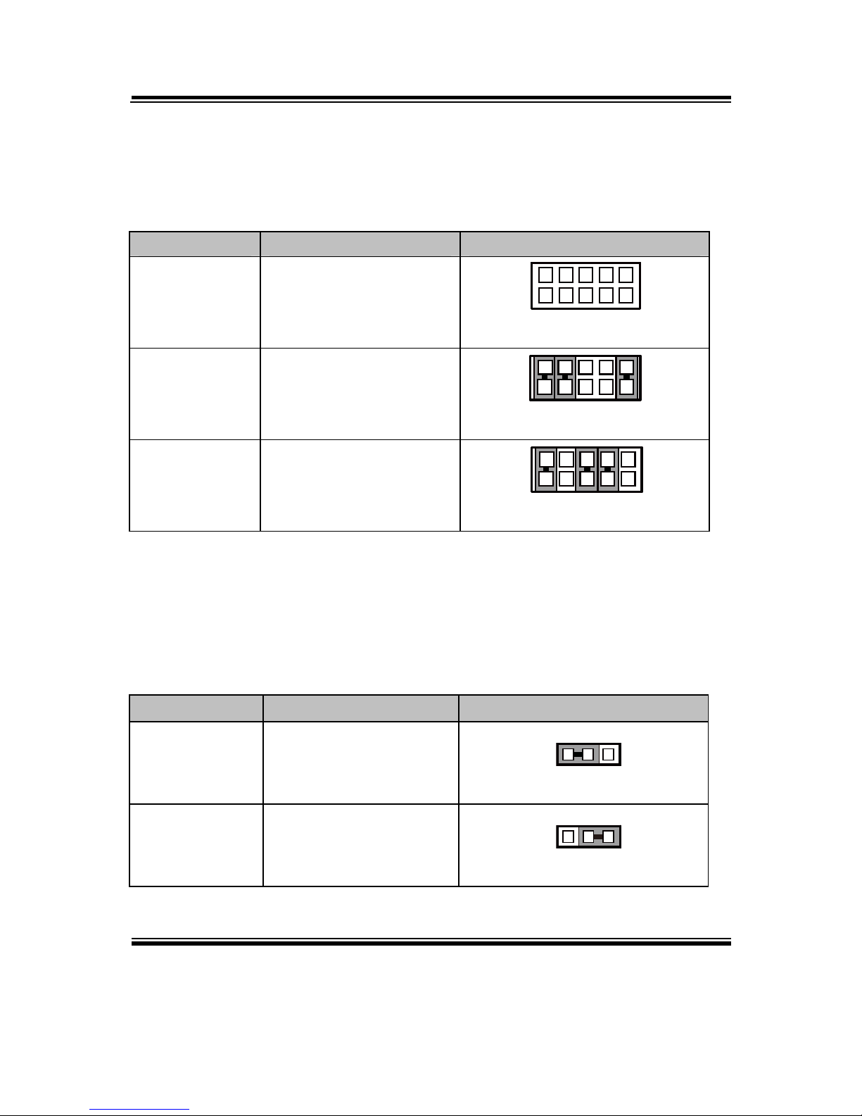
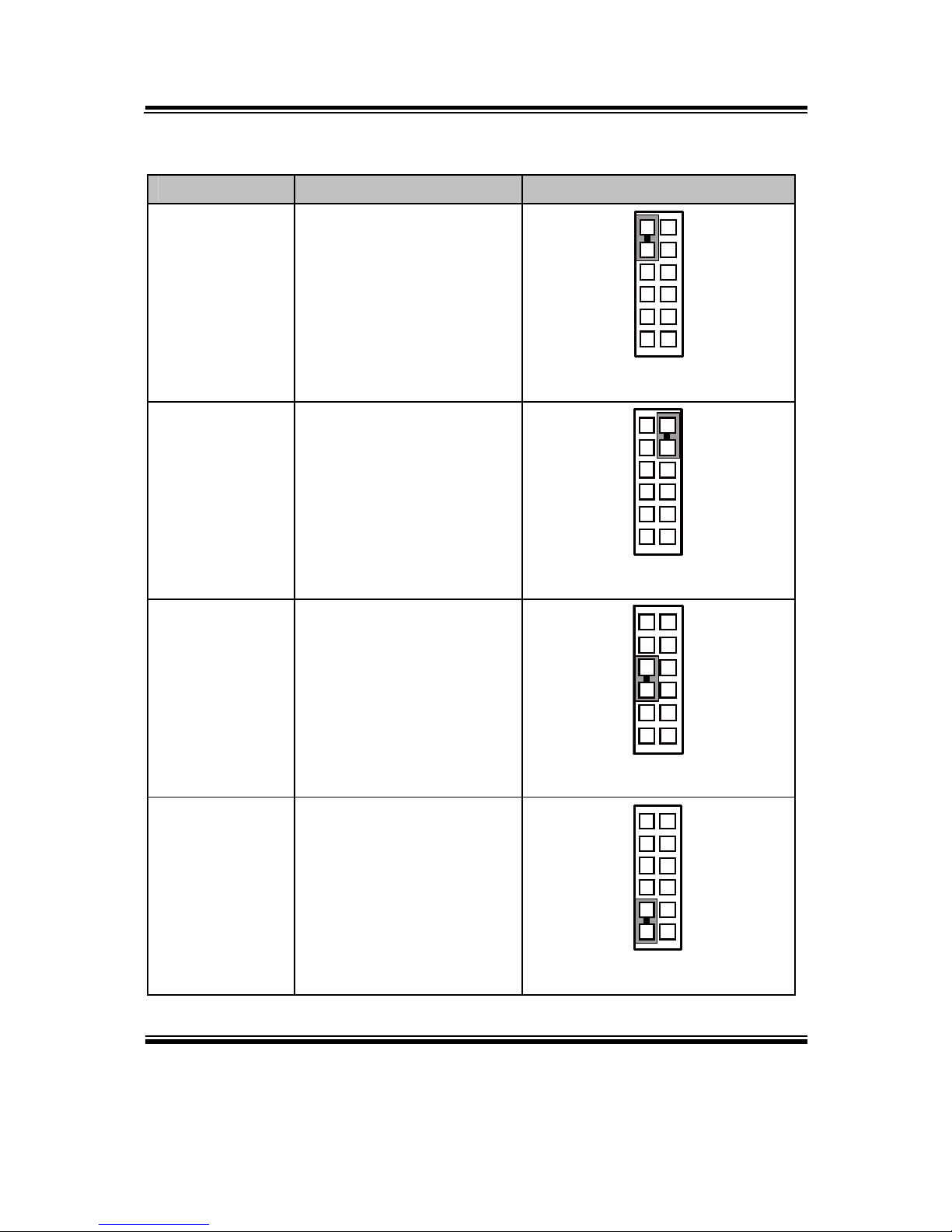
2-5. COM PORT RI & VOLTAGE SELECTION
JP_COM3 & JP_COM4: COM3 & COM4 Port RI & Voltage Selection
The pin assignments are as follows:
SELECTION JUMPTER SETTING
JUMPER ILLUSTRATION
RI 1-2
216
5
JP_COM3/
JP_COM4/
12V 3-4
2
1
6
5
JP_COM3/
JP_COM4/
5V 5-6
2
1
6
5
JP_COM3/
JP_COM4/
Note: Manufacturing default is RI.
6 1
10 5
COM6
Chapter 2 Hardware Configuration
BA-0951 USER′S MANUAL
Page: 2-9
2-6. RS-232/422/485 (COM2) SELECTION
JP8: RS-232/422/485 (COM2) Selection Connector, used to set COM2 function.
The jumper settings are as follows:
SELECTION JUMPER SETTINGS JUMPER ILLUSTRATION
RS-232 All Open
10
9
2
1
JP8
RS-422
1-2,
3-4,
9-10
10
9
2
1
JP8
RS-485
1-2,
5-6,
7-8
10
9
2
1
JP8
Note: Manufacturing default is RS-232.
2-7. COM2 AUTO DETECT SELECTION
JP7: COM2 Auto Detect Selection
The jumper settings are as follows:
SELECTION JUMPER SETTINGS JUMPER ILLUSTRATION
Normal 1-2
1
3
JP7
Auto Gating 2-3
1
3
JP7
Note: Manufacturing default is Normal.
Chapter 2 Hardware Configuration
BA-0951 USER′S MANUAL
Page: 2-10
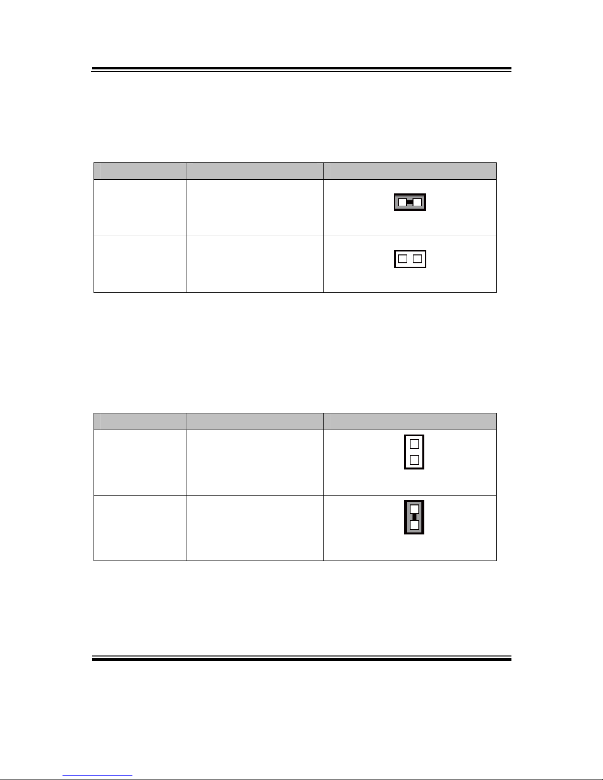
2-8. BIOS RECOVERY MODE SELECTION
JP1: BIOS Recovery Mode Selection
The selections are as follows:
SELECTION JUMPER SETTINGS JUMPER ILLUSTRATION
Normal Close
1
JP1
Recovery Open
1
JP1
Note: Manufacturing Default is Normal.
2-9. CLEAR CMOS DATA SELECTION
JP4: Clear CMOS Data Selection
The selections are as follows:
SELECTION JUMPER SETTINGS JUMPER ILLUSTRATION
Normal Open
1
JP4
Clear CMOS* Close
1
JP4
Note: Manufacturing Default is Normal.
*To clear CMOS data, user must power-off the computer and set the jumper to “Clear
CMOS” as illustrated above. After five to six seconds, set the jumper back to
“Normal” and power-on the computer.
Chapter 2 Hardware Configuration
BA-0951 USER′S MANUAL
Page: 2-11
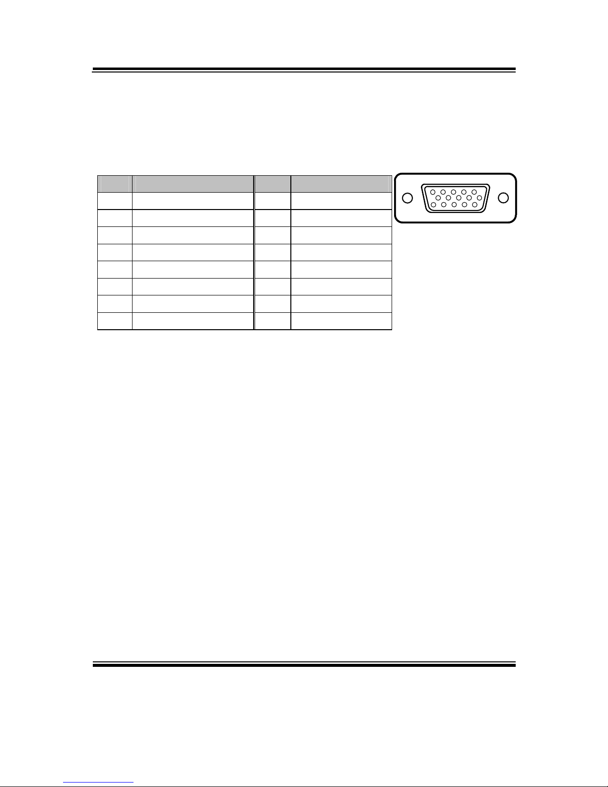
2-10. VGA PORT
VGA1: VGA Port
The pin assignments are as follows:
PIN ASSIGNMENT PIN ASSIGNMENT
1 CRTRED 9 CRTVCC_L
2 CRTGREEN 10 GND
3 CRTBLUE 11 NC
4 NC 12 CRTDATA
5 GND 13 HSYNC
6 CRT_ALWAYS_ON 14 VSYNC
7 GND 15 CRTCLK
8 GND
15
610
1115
VGA1
Chapter 2 Hardware Configuration
BA-0951 USER′S MANUAL
Page: 2-12
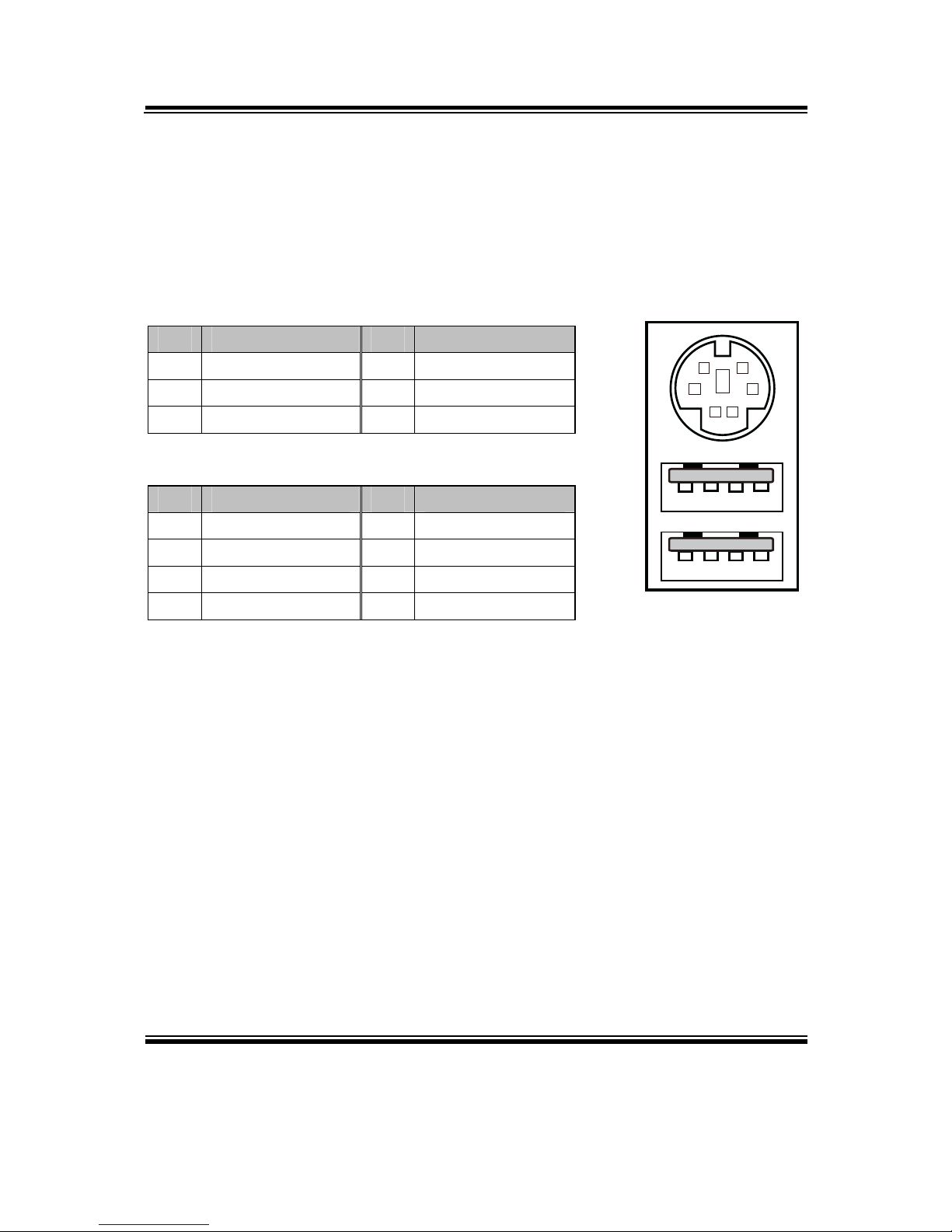
2-11. MINI-DIN & USB PORT
JPS2USB1: Mini-DIN & Two USB2.0 Ports
Mini-DIN port supports keyboard, Y-cable and PS/2 mouse.
The pin assignments are as follows:
Mini-DIN Port:
PIN ASSIGNMENT PIN ASSIGNMENT
9 GND 12 5VDUAL
10 KDAT 13 KCLK
11 MDAT 14 MCLK
USB Ports:
PIN ASSIGNMENT PIN ASSIGNMENT
1 GND 5 GND
2 USB3+ 6 USB2+
3 USB3- 7 USB2-
4 VCC5 8 VCC5
4
1
85
9
1011
12
1314
JPS2USB1
Chapter 2 Hardware Configuration
BA-0951 USER′S MANUAL
Page: 2-13
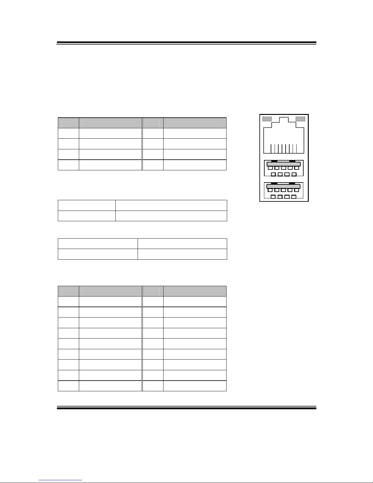
2-12. LAN & USB PORT
LAN1_USB1: LAN & Two USB3.0 Ports
The pin assignments are as follows:
LAN1 signal:
PIN ASSIGNMENT PIN ASSIGNMENT
1 LAN1_MDI0_DP 5 LAN1_MDI2_DP
2 LAN1_MDI0_DN 6 LAN1_MDI2_DN
3 LAN1_MDI1_DP 7 LAN1_MDI3_DP
4 LAN1_MDI1_DN 8 LAN1_MDI3_DN
LAN LED Indicator:
Left Side LED
Red Color On Giga LAN Speed Indicator
Off No LAN switch/hub connected.
Right Side LED
Orange Color Blinking LAN Message Active
Off No LAN Message Active
USB signal:
PIN ASSIGNMENT PIN ASSIGNMENT
A1 VCCUSB1 B1 VCCUSB1
A2 USB_N0 B2 USB_N1
A3 USB_P0 B3 USB_P1
A4 GND B4 GND
A5 USB3_RX1_DN B5 USB3_RX2_DN
A6 USB3_RX1_DP B6 USB3_RX2_DP
A7 GND B7 GND
A8 USB3_TX1_DN B8 USB3_TX2_DN
A9 USB3_TX1_DP B9 USB3_TX2_DP
Red Orange
B1 B4
B9 B5
A1 A4
A9 A5
8 1
LAN1_USB1
Chapter 2 Hardware Configuration
BA-0951 USER′S MANUAL
Page: 2-14
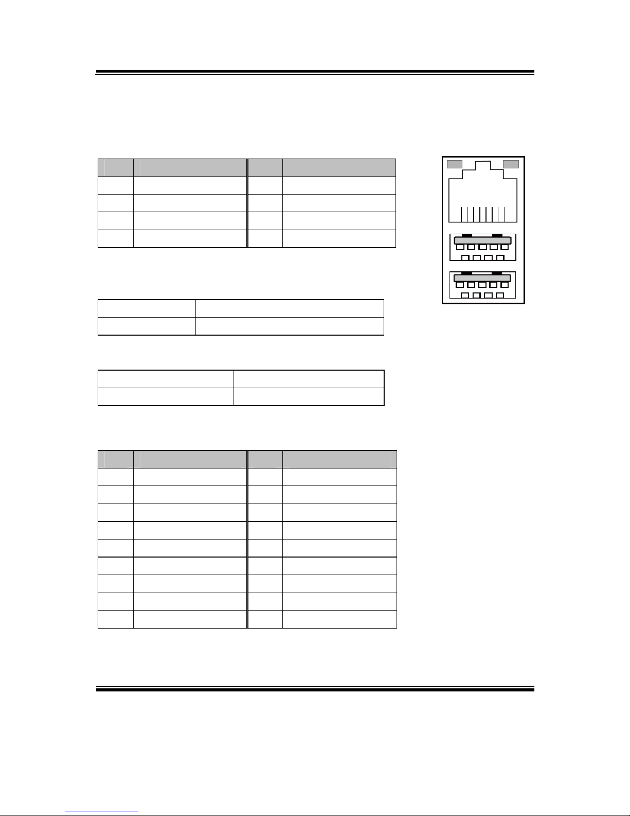
LAN2_USB2: LAN & Two USB3.0 Ports
The pin assignments are as follows:
LAN2 signal:
PIN ASSIGNMENT PIN ASSIGNMENT
1 LAN2_MDI0_DP 5 LAN2_MDI2_DP
2 LAN2_MDI0_DN 6 LAN2_MDI2_DN
3 LAN2_MDI1_DP 7 LAN2_MDI3_DP
4 LAN2_MDI1_DN 8 LAN2_MDI3_DN
LAN LED Indicator:
Left Side LED
Red Color On Giga LAN Speed Indicator
Off No LAN switch/hub connected.
Right Side LED
Orange Color Blinking LAN Message Active
Off No LAN Message Active
USB signal:
PIN ASSIGNMENT PIN ASSIGNMENT
A1 VCCUSB1 B1 VCCUSB1
A2 USB_N4 B2 USB_N5
A3 USB_P4 B3 USB_P5
A4 GND B4 GND
A5 USB3_RX5_DN B5 USB3_RX6_DN
A6 USB3_RX5_DP B6 USB3_RX6_DP
A7 GND B7 GND
A8 USB3_TX5_DN B8 USB3_TX6_DN
A9 USB3_TX5_DP B9 USB3_TX6_DP
Red Orange
B1 B4
B9 B5
A1 A4
A9 A5
8 1
LAN2_USB2

Chapter 2 Hardware Configuration
BA-0951 USER′S MANUAL
Page: 2-15
2-13. USB CONNECTOR
USB6_1: Universal Serial Bus Connector
The pin assignments are as follows:
PIN ASSIGNMENT PIN ASSIGNMENT
1 USB_67_VCC5 6 USB_P7
2 USB_67_VCC5 7 GND
3 USB_N6 8 GND
4 USB_N7 9 NC
5 USB_P6 10 GND
USB8_1: Universal Serial Bus Connector
The pin assignments are as follows:
PIN ASSIGNMENT PIN ASSIGNMENT
1 USB_89_VCC5 6 USB_P9
2 USB_89_VCC5 7 GND
3 USB_N8 8 GND
4 USB_N9 9 NC
5 USB_P8 10 GND
USB10_1: Universal Serial Bus Connector
The pin assignments are as follows:
PIN ASSIGNMENT PIN ASSIGNMENT
1 USB_1011_VCC5 6 USB_P11
2 USB_1011_VCC5 7 GND
3 USB_N10 8 GND
4 USB_N11 9 NC
5 USB_P10 10 GND
1
2
9
10
USB6_1/
USB8_1/
USB10_1
Chapter 2 Hardware Configuration
BA-0951 USER′S MANUAL
Page: 2-16
2-14. TPM CONNECTOR
JLPC1: TPM Connector
The pin assignments are as follows:
PIN ASSIGNMENT PIN ASSIGNMENT
1 CLK 11 LAD0
2 GND 12 GND
3 FRAME 13 SMBCLK
4 NC 14 SMBDATA
5 RESET 15 3VSB
6 VCC5 16 SERIRQ
7 LAD3 17 GND
8 LAD2 18 CLK RUN
9 VCC3 19 SUS_TAT
10 LAD1 20 DREQ0
2-15. FRONT PANEL CONNECTOR & SELECTION
FP1: Front Panel Connector
The pin assignments are as follows:
PIN ASSIGNMENT PIN ASSIGNMENT
1 HDD_LED+ 7 RST_BTN
2 PWR_LED+ 8 SPEAKER SIGNAL
3 HDD_LED- 9 GND
4 PWR_LED- 10 SPEAKER SIGNAL
5 GND 11 PWRBTNSW
6 SPK_VCC 12 SPEAKER SIGNAL
11 12
1 2
FP1
20
21
19
JLPC1
Chapter 2 Hardware Configuration
BA-0951 USER′S MANUAL
Page: 2-17
Front Panel selections are as follows:
SELECTION JUMPER SETTINGS JUMPER ILLUSTRATION
HDD LED 1-3
1
2
11
12
FP1
Power LED 2-4
1
2
11 12
FP1
Reset Button 5-7
1
2
1112
FP1
ATX Power
Button
9-11
1
2
11 12
FP1
Chapter 2 Hardware Configuration
BA-0951 USER′S MANUAL
Page: 2-18
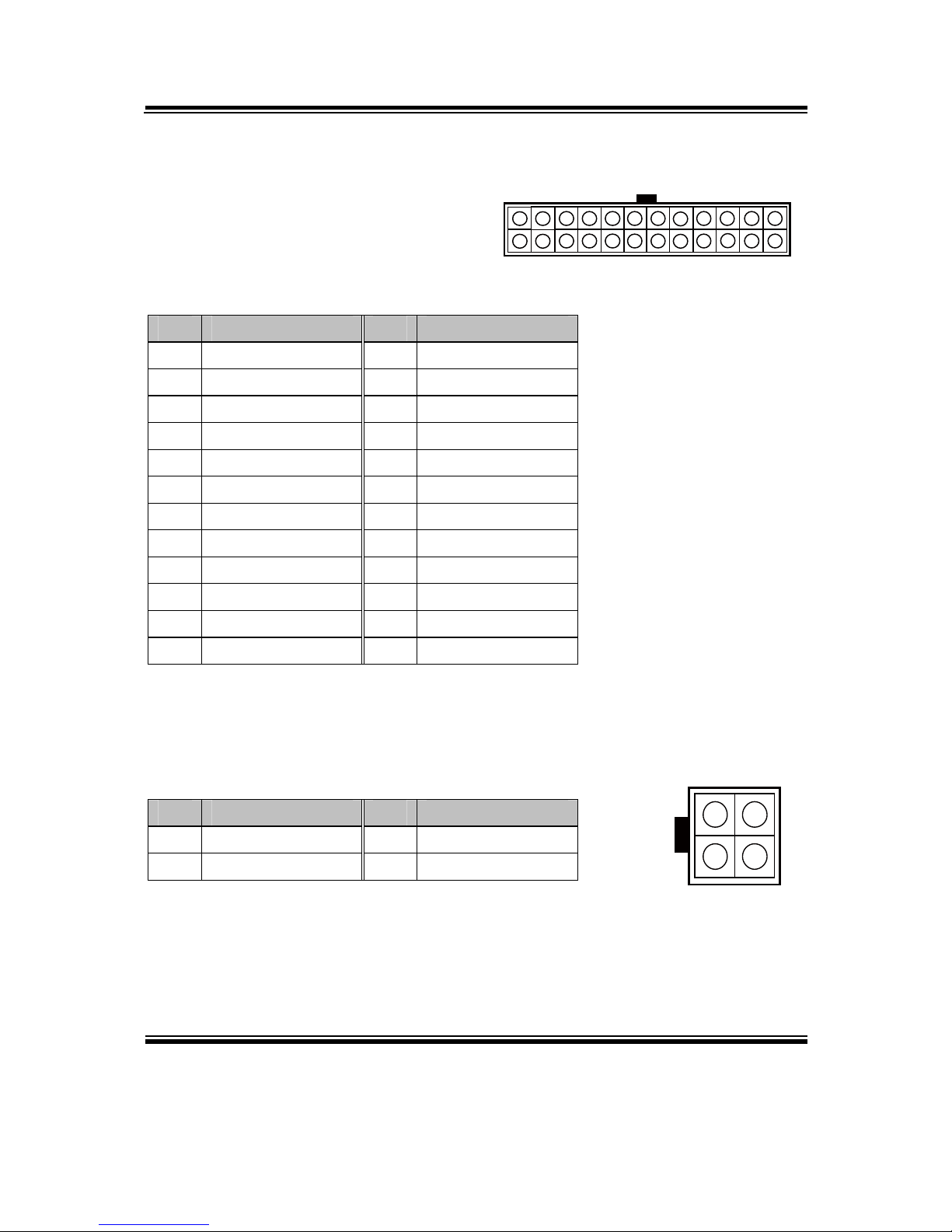
2-16. ATX POWER CONNECTOR
ATX_PWR1: ATX Power Connector
The pin assignments are as follows:
PIN ASSIGNMENT PIN ASSIGNMENT
1 +3.3V 13 +3.3V
2 +3.3V 14 -12V
3 GND 15 GND
4 +5V 16 PSON
5 GND 17 GND
6 +5V 18 GND
7 GND 19 GND
8 PWROK 20 -5V
9 5VSB 21 +5V
10 +12V 22 +5V
11 +12V 23 +5V
12 +3.3V 24 GND
ATX_PWR2: ATX Power Connector
The pin assignments are as follows:
PIN ASSIGNMENT PIN ASSIGNMENT
1 GND 3 12V
2 GND 4 12V
1
12
24
13
ATX_PWR1
1
2
3
4
ATX_PWR2
Chapter 2 Hardware Configuration
BA-0951 USER′S MANUAL
Page: 2-19
2-17. SATA CONNECTOR
SATA1~SATA6: Six Serial ATA Connectors
The pin assignments are as follows:
SATA1:
PIN ASSIGNMENT PIN ASSIGNMENT
1 GND 5 SATA_RXN_0_C
2 SATA_TXP_0_C 6 SATA_RXP_0_C
3 SATA_TXN_0_C 7 GND
4 GND
SATA2:
PIN ASSIGNMENT PIN ASSIGNMENT
1 GND 5 SATA_RXN_1_C
2 SATA_TXP_1_C 6 SATA_RXP_1_C
3 SATA_TXN_1_C 7 GND
4 GND
SATA3:
PIN ASSIGNMENT PIN ASSIGNMENT
1 GND 5 SATA_RXN_2_C
2 SATA_TXP_2_C 6 SATA_RXP_2_C
3 SATA_TXN_2_C 7 GND
4 GND
SATA4:
PIN ASSIGNMENT PIN ASSIGNMENT
1 GND 5 SATA_RXN_3_C
2 SATA_TXP_3_C 6 SATA_RXP_3_C
3 SATA_TXN_3_C 7 GND
4 GND
SATA5:
17
SATA1/
SATA2/
SATA3/
SATA4/
Chapter 2 Hardware Configuration
BA-0951 USER′S MANUAL
Page: 2-20
PIN ASSIGNMENT PIN ASSIGNMENT
1 GND 5 SATA_RXN_4_C
2 SATA_TXP_4_C 6 SATA_RXP_4_C
3 SATA_TXN_4_C 7 GND
4 GND
SATA6:
PIN ASSIGNMENT PIN ASSIGNMENT
1 GND 5 SATA_RXN_5_C
2 SATA_TXP_5_C 6 SATA_RXP_5_C
3 SATA_TXN_5_C 7 GND
4 GND
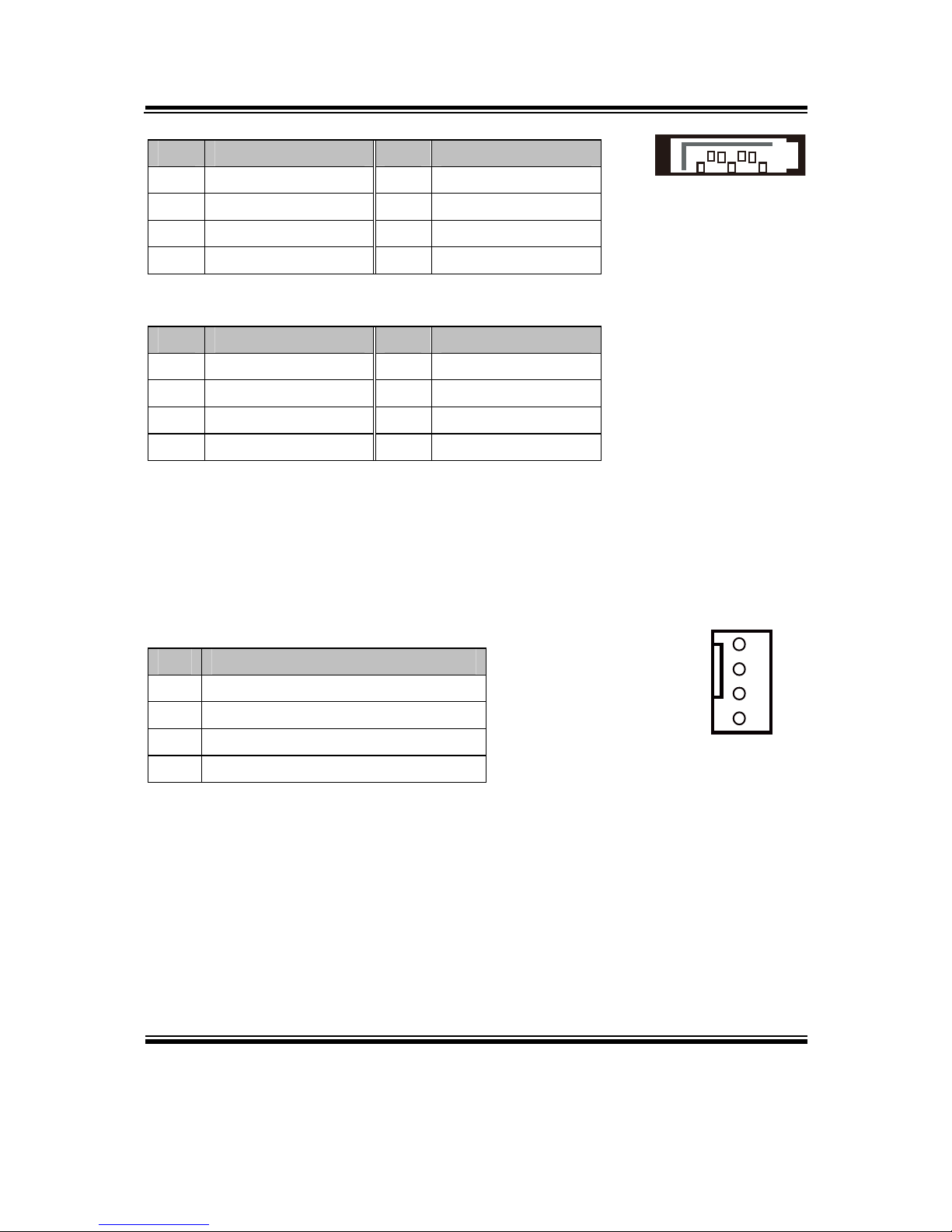
2-18. CPU FAN CONNECTOR
CPU_FAN1: CPU Fan Connector
The pin assignments are as follows:
PIN ASSIGNMENT
1 GND
2 VCC12
3 FAN_TAC1
4 FAN_CTL1
1
4
CPU_FAN1
17
SATA5/
SATA6/

Chapter 2 Hardware Configuration
BA-0951 USER′S MANUAL
Page: 2-21
2-19. SYSTEM FAN CONNECTOR
SYS_FAN1~SYS_FAN4: System Fan Connectors
The pin assignments are as follows:
SYS_FAN1:
PIN ASSIGNMENT
1 GND
2 VCC12
3 SYS_FAN_IN
4 SYS_FAN_CTL
SYS_FAN2:
PIN ASSIGNMENT
1 GND
2 VCC12
3 FAN_IN1
4 FAN_CTL1
SYS_FAN3:
PIN ASSIGNMENT
1 GND
2 VCC12
3 FAN_IN2
4 FAN_CTL2
SYS_FAN4:
PIN ASSIGNMENT
1 GND
2 VCC12
3 FAN_IN3
4 FAN_CTL3
1
4
SYS_FAN1/
SYS_FAN3/
SYS_FAN4/
4 1
SYS_FAN2

Chapter 2 Hardware Configuration
BA-0951 USER′S MANUAL
Page: 2-22
2-20. PRINTER PORT
LPT1: Printer Port
The pin assignments are as follows:
PIN ASSIGNMENT PIN ASSIGNMENT
1 STB 14 AFD#
2 PDR0 15 ERR#
3 PDR1 16 INIT#
4 PDR2 17 SLIN#
5 PDR3 18 GND
6 PDR4 19 GND
7 PDR5 20 GND
8 PDR6 21 GND
9 PDR7 22 GND
10 ACK# 23 GND
11 BUSY 24 GND
12 PE 25 GND
13 SLCT
113
25 14
LPT1

Chapter 2 Hardware Configuration
BA-0951 USER′S MANUAL
Page: 2-23
2-21. DISPLAY PORT CONNECTOR
JDP1, JDP2 & JDP3: Display Port Connectors
The pin assignments are as follows:
JDP1:
PIN ASSIGNMENT PIN ASSIGNMENT
1 DP_B_DATA0+ 11 GND
2 GND 12 DP_B_DATA3-
3 DP_B_DATA0- 13 DP_B_AUX_ENJ
4 DP_B_DATA1+ 14 GND
5 GND 15 DP_B_AUX+
6 DP_B_DATA1- 16 DP_B_HPD
7 DP_B_DATA2+ 17 DP_B_AUX-
8 GND 18 DP_VCC3_3
9 DP_B_DATA2- 19 DP_VCC5
10 DP_B_DATA3+ 20 DP_VCC3_3
JDP2:
PIN ASSIGNMENT PIN ASSIGNMENT
1 DP_C_DATA0+ 11 GND
2 GND 12 DP_C_DATA3-
3 DP_C_DATA0- 13 DP_C_AUX_ENJ
4 DP_C_DATA1+ 14 GND
5 GND 15 DP_C_AUX+
6 DP_C_DATA1- 16 DP_C_HPD
7 DP_C_DATA2+ 17 DP_C_AUX-
8 GND 18 DP_VCC3_3
9 DP_C_DATA2- 19 DP_VCC5
10 DP_C_DATA3+ 20 DP_VCC3_3
19 20
21
JDP1/
JDP2/

Chapter 2 Hardware Configuration
BA-0951 USER′S MANUAL
Page: 2-24
JDP3:
PIN ASSIGNMENT PIN ASSIGNMENT
1 DP_D_DATA0+ 11 GND
2 GND 12 DP_D_DATA3-
3 DP_D_DATA0-
13 DP_D_AUX_ENJ
4 DP_D_DATA1+ 14 GND
5 GND 15 DP_D_AUX+
6 DP_D_DATA1-
16 DP_D_HPD
7 DP_D_DATA2+ 17 DP_D_AUX-
8 GND 18 DP_VCC3_3
9 DP_D_DATA2-
19 DP_VCC5
10 DP_D_DATA3+ 20 DP_VCC3_3
2-22. DIGITAL INPUT/OUTPUT CONNECTOR
DIO1: Digital I/O Connectors
The pin assignments are as follows:
PIN ASSIGNMENT PIN ASSIGNMENT
1 VCC5 6 DOUT_H1
2 GND 7 DIN_H2
3 DIN_H0 8 DOUT_H2
4 DOUT_H0 9 DIN_H3
5 DIN_H1 10 DOUT_H3
1
2
9
10
DIO1
19 20
21
JDP3/

Chapter 2 Hardware Configuration
BA-0951 USER′S MANUAL
Page: 2-25
2-23. AUDIO PORT & CONNECTOR
AUDIO1: AUDIO Ports, including Line-In, Line-Out & Microphone
The connector can support only MIC Connector.
The pin assignments are as follows:
Line-In:
PIN ASSIGNMENT
32 HD_LINE-IN-L
33 GND
34 GND
35 HD_LINE-IN-R
Line-Out:
PIN ASSIGNMENT
22 LINE-OUT-L
23 GND
24 GND
25 LINE-OUT-R
Mic-In:
PIN ASSIGNMENT
1 GND
2 HD_MIC1-L
3 GND
4 GND
5 HD_MIC1-R
SPDIF (Optionally used with the same port as Line-In):
PIN ASSIGNMENT
42 GND
43 VCC_AUD
44 SPDIF OUT
1 2345
22232425
32333435
424344
AUDIO1

Chapter 2 Hardware Configuration
BA-0951 USER′S MANUAL
Page: 2-26
AUDIO2: AUDIO Ports, including Line-In, Line-Out & Microphone
The pin assignments are as follows:
PIN ASSIGNMENT PIN ASSIGNMENT
1 HD_MIC1-L 6 HD_LINE-IN-R
2 HD_MIC1-R 7 GND
3 GND 8 GND
4 GND 9 LINE-OUT-L
5 HD_LINE-IN-L 10 LINE-OUT-R
1
2
9
10
AUDIO2

Page: 3-1
SOFTWARE
UTILITIES
This chapter comprises the detailed information of VGA driver, LAN
driver, and Sound driver.
Sections included:
Introduction.
Intel® Chipset Software Installation Utility
Intel® Rapid Storage Technology Utility
Intel® USB3.0 eXtensible Host Controller Utility
Intel® Management Engine Components Utility
VGA Driver Utility
LAN Driver Utility
Sound Driver Utility
CHAPTER
3

Chapter 3 Software Utilities
BA-0951 USER′S MANUAL
Page:3-2
3-1. INTRODUCTION
Enclosed with our BA-0951 package are our driver utilities, which come in a format
of CD ROM or floppy disk. Refer to the following table for driver locations:
FILENAME (Assume that CD ROM drive is D:) PURPOSE
D:\DRIVER\Platform\Win7(32-bit)\UTILITY
D:\DRIVER\Platform\Win7(64-bit)\UTILITY
D:\DRIVER\Platform\Win8(32-bit)\UTILITY
D:\DRIVER\Platform\Win8(64-bit)\UTILITY
D:\DRIVER\Platform\Server2008R2(64-bit)\UTILITY
Intel® chipset device
software installation
utility
D:\DRIVER\Platform\Win7(32-bit)\Intel RST
D:\DRIVER\Platform\Win7(64-bit)\Intel RST
D:\DRIVER\Platform\Win8(32-bit)\Intel RST
D:\DRIVER\Platform\Win8(64-bit)\Intel RST
D:\DRIVER\Platform\Server2008R2(64-bit)\Intel RST
Intel® Rapid Storage
Technology (RAID)
driver installation
D:\DRIVER\Platform\Win7(32-bit)\USB3
D:\DRIVER\Platform\Win7(64-bit)\USB3
D:\DRIVER\Platform\Server2008R2(64-bit)\USB3
Intel®
USB3.0 eXtensible
host controller
D:\DRIVER\Platform\Win7(32-bit)\ME
D:\DRIVER\Platform\Win7(64-bit)\ME
D:\DRIVER\Platform\Win8(32-bit)\ME
D:\DRIVER\Platform\Win8(64-bit)\ME
D:\DRIVER\Platform\Server2008R2(64-bit)\ME
Intel® Management
Engine Interface
D:\DRIVER\Platform\Win7(32-bit)\VGA
D:\DRIVER\Platform\Win7(64-bit)\VGA
D:\DRIVER\Platform\Win8(32-bit)\VGA
D:\DRIVER\Platform\Win8(64-bit)\VGA
D:\DRIVER\Platform\Server2008R2(64-bit)\VGA
Intel® HD Graphics
Family for VGA driver
installation
D:\DRIVER\Platform\Win7(32-bit)\LAN
D:\DRIVER\Platform\Win7(64-bit)\LAN
D:\DRIVER\Platform\Win8(32-bit)\LAN
D:\DRIVER\Platform\Win8(64-bit)\LAN
D:\DRIVER\Platform\ Server2008R2(64-bit)\LAN
Intel® I217-LM/V &
I210-AT for LAN driver
installation

Chapter 3 Software Utilities
BA-0951 USER′S MANUAL
Page:3-3
FILENAME (Assume that CD ROM drive is D:) PURPOSE
D:\DRIVER\Platform\Win7(32-bit)\SOUND
D:\DRIVER\Platform\Win7(64-bit)\SOUND
D:\DRIVER\Platform\Win8(32-bit)\SOUND
D:\DRIVER\Platform\Win8(64-bit)\SOUND
D:\DRIVER\Platform\Server2008R2(64-bit)\SOUND
Realtek ALC888S for
sound driver installation
D:\DRIVER\Platform\Win7(32-bit)\F6Floppy
D:\DRIVER\Platform\Win7(64-bit)\F6Floppy
D:\DRIVER\Platform\Win8(32-bit)\F6Floppy
D:\DRIVER\Platform\Win8(64-bit)\F6Floppy
D:\DRIVER\Platform\ Server2008R2(64-bit)\F6Floppy
Intel® F6 Floppy utility
D:\DRIVER\Flash BIOS Aptio (EFI) BIOS update
utility
Note: Be sure to install the Utility right after the OS fully installed.

Chapter 3 Software Utilities
BA-0951 USER′S MANUAL
Page:3-4
3-2. INTEL® C HIPSET SOFTWARE INSTALLATION UTILITY
3-2-1. Introduction
The Intel® Chipset Device Software installs Windows INF files to the target system.
These files outline to the operating system how to configure the Intel® chipset
components in order to ensure that the following features function properly:
Core PCI and ISAPNP Services
PCIe Support
IDE/ATA33/ATA66/ATA100 Storage Support
SATA Storage Support
USB Support
Identification of Intel® Chipset Components in the Device Manager
3-2-2. Installation of Utility for Windows /7/8/Server 2008 R2
The Utility Pack is to be installed only for Windows 7/8/Server 2008 R2 series, and it
should be installed right after the OS installation. Please follow the steps below:
1. Insert the driver disk into a CD ROM device.
2. Under Windows system, go to the directory where the Utility driver is located.
3. Run the application with administrative privileges.

Chapter 3 Software Utilities
BA-0951 USER′S MANUAL
Page:3-5
3-3. INTEL® RAPID STORAGE TECHNOLOGY UTILITY
3-3-1. Introduction
The Intel® RST driver utility supports RAID 0, 1, 5 and 10 and fully compatible with
Windows 7/8/Server 2008 R2, and it should be installed after the operating system is
installed completely. Perform F6 and RAID BIOS configurations prior to installation
of this driver for proper operation.
3-3-2. Installation of RST Driver for Windows 7/8/Server 2008 R2
1. Insert the driver disk into a CD ROM device.
2. Under Windows system, go to the directory where the RST driver is located.
3. Run the application with administrative privileges.

Chapter 3 Software Utilities
BA-0951 USER′S MANUAL
Page:3-6
3-4. INTEL® USB3.0 EXTENSIBLE HOST CONTROLLER
UTILITY
3-4-1. Introduction
Intel® USB 3.0 eXtensible Host Controller Driver supports the following Intel®
Chipsets/Processors:
4th Generation Intel® Core™ Processor Family
Intel® 8 Series/C220 Series Chipset Family
4th Generation U-Series Platform I/O
3-4-2. Installation Instructions for Windows 7/Server 2008 R2
1. Insert the driver disk into a CD ROM device.
2. Under Windows system, go to the directory where the driver is located.
3. Run the application with administrative privileges.

Chapter 3 Software Utilities
BA-0951 USER′S MANUAL
Page:3-7
3-5. INTEL® MANAGEMENT ENGINE COMPONENTS UTILITY
3-5-1. Introduction
The Intel® ME software components that need to be installed depend on the system's
specific hardware and firmware features. The installer, compatible with Windows
7/8/Server 2008 R2, detects the system's capabilities and installs the relevant drivers
and applications.
3-5-2. Installation Instructions for Windows 7/8/Server 2008 R2
1. Insert the driver disk into a CD ROM device.
2. Under Windows system, go to the directory where the driver is located.
3. Run the application with administrative privileges.

Chapter 3 Software Utilities
BA-0951 USER′S MANUAL
Page:3-8
3-6. VGA DRIVER UTILITY
3-6-1. Introduction
The VGA interface embedded with our BA-0951 can support a wide range of display.
You can display CRT simultaneously with the same mode.
1. Win 7 Series
2. Win 8 Series
3. Win Server 2008 R2 - 64 bit
3-6-2. Installation of VGA Driver
To install the VGA Driver, simply follow the following steps:
1. Insert the driver disk into a CD ROM device.
2. Under Windows system, go to the directory where the VGA driver is located.
3. Run the application with administrative privileges..

Chapter 3 Software Utilities
BA-0951 USER′S MANUAL
Page:3-9
3-7. LAN DRIVER UTILITY
3-7-1. Introduction
BA-0951 is enhanced with LAN function that can support various network adapters.
Installation programs for LAN drivers are listed as follows:
1. Win 7 Series
2. Win 8 Series
3. Win Server 2008 R2 - 64 bit
For more details on Installation procedure, please refer to Readme.txt file found
on LAN Driver Utility.

Chapter 3 Software Utilities
BA-0951 USER′S MANUAL
Page:3-10
3-8. SOUND DRIVER UTILITY
3-8-1. Introduction
The Realtek sound function enhanced in this system is fully compatible with Windows
7/8/Server 2008 R2. Below, you will find the content of the Sound driver:
1. Win 7 Series
2. Win 8 Series
3. Win Server 2008 R2 - 64 bit
3-8-2. Installation of Sound Driver
1. Insert the driver disk into a CD ROM device.
2. Under Windows system, go to the directory where the Sound driver is located.
3. Run the application with administrative privileges..
4. Follow the instructions on the screen to complete the installation.
5. Once the installation is completed, shut down the system and restart in order for
the changes to take effect.

Page: 4-1
BIOS SETUP
This chapter shows how to set up the BIOS.
Sections included:
Introduction
Entering Setup
Main
Advanced
Chipset
Boot
Security
Save & Exit
CHAPTER
4

Chapter 4 BIOS Setup
BA-0951 USER′S MANUAL
Page: 4-2
4-1. INTRODUCTION
The board BA-0951 uses an AMI Aptio BIOS that is stored in the Serial Peripheral
Interface Flash Memory (SPI Flash) and can be updated. The SPI Flash contains the
BIOS Setup program, Power-on Self-Test (POST), the PCI auto-configuration utility,
LAN EEPROM information, and Plug and Play support.
Aptio is AMI’s BIOS firmware based on the UEFI (Unified Extensible Firmware
Interface) Specifications and the Intel Platform Innovation Framework for EFI. The
UEFI specification defines an interface between an operating system and platform
firmware. The interface consists of data tables that contain platform-related
information, boot service calls, and runtime service calls that are available to the
operating system and its loader. These provide standard environment for booting an
operating system and running pre-boot applications. Following illustration shows
Extensible Firmware Interface’s position in the software stack.

Chapter 4 BIOS Setup
BA-0951 USER′S MANUAL
Page: 4-3
EFI BIOS provides an user interface allow users the ability to modify hardware
configuration, e.g. change system date and time, enable or disable a system component,
decide bootable device priorities, setup personal password, etc., which is convenient
for modifications and customization of the computer system and allows technicians
another method for finding solutions if hardware has any problems.
The BIOS Setup program can be used to view and change the BIOS settings for the
computer. The BIOS Setup program is accessed by pressing the <Del> or <ESC> key
after the POST memory test begins and before the operating system boot begins. The
settings are shown below.

Chapter 4 BIOS Setup
BA-0951 USER′S MANUAL
Page: 4-4
4-2. ENTERING SETUP
When the system is powered on, the BIOS will enter the Power-On Self Test (POST)
routines and the following message will appear on the lower screen:
Version: 2.15.1236. Copyright (C) 2012 American Magatrends, Inc.
BIOS Date: 06/10/2013 10:57:35 Ver: B9510PW1
Press <CTRL + P> to enter MEBX setup menu.
Press <DEL> or <ESC> to enter setup.
99
POST screen
As long as this message is present on the screen you may press the <Del> key (the one
that shares the decimal point at the bottom of the number keypad) to access the Setup
program. In a moment, the main menu of the Aptio Setup Utility will appear on the
screen:

Chapter 4 BIOS Setup
BA-0951 USER′S MANUAL
Page: 4-5
BIOS setup program initial screen
You may move the cursor by up/down keys to highlight the individual menu items. As
you highlight each item, a brief description of the highlighted selection will appear at
the bottom of the screen.

Chapter 4 BIOS Setup
BA-0951 USER′S MANUAL
Page: 4-6
4-3. MAIN
Main screen
BIOS Setting Options Description/Purpose
BIOS Vendor No changeable options Displays the BIOS vendor.
Core Version No changeable options Displays the current BIOS core
version.
Compliancy No changeable options Displays the current UEFI version.
BIOS Version No changeable options Displays the version of the BIOS
currently installed on the platform.
Build Date and
Time
No changeable options Displays the date of current BIOS
version.
ME FW
Version
No changeable options Displays the current ME version.
ME Firmware
SKU
No changeable options Displays the current ME SKU.

Chapter 4 BIOS Setup
BA-0951 USER′S MANUAL
Page: 4-7
BIOS Setting Options Description/Purpose
System Date Month, day, year Specifies the current date.
System Time Hour, minute, second Specifies the current time.
Access Level No changeable options Displays the current user level.

Chapter 4 BIOS Setup
BA-0951 USER′S MANUAL
Page: 4-8
4-4. ADVANCED
Advanced screen
BIOS Setting Options Description/Purpose
ACPI Settings Sub-Menu System ACPI Parameters.
Trusted Computing Sub-Menu Trusted Computing settings.
CPU Configuration Sub-Menu CPU Configuration. Parameters.
SATA Configuration Sub-Menu SATA Configuration Parameters.
AMT Configuration Sub-Menu Configure Active Management
Technology parameters.
USB Configuration Sub-Menu USB Configuration Parameters.
F81866 Super IO
Configuration
Sub-Menu Super IO Configuration
Parameters.
F81866 H/W
Monitor
Sub-Menu Monitor hardware status.

Chapter 4 BIOS Setup
BA-0951 USER′S MANUAL
Page: 4-9
4-4-1. ACPI Settings
ACPI settings screen
BIOS Setting Options Description/Purpose
Enable
Hibernation
- Disabled
- Enabled
Enables or Disables System ability to
Hibernate (OS/S4 Sleep State). This
option may be not effective with
some OS.
ACPI Sleep
State
- Suspend Disabled
- S3 only (Suspend to
RAM)
Specifies the ACPI sleep state.
Suspend Disabled disables ACPI
sleep feature.
S3 mode allows the platform to
enter Suspend to RAM mode.

Chapter 4 BIOS Setup
BA-0951 USER′S MANUAL
Page: 4-10
4-4-2. Trusted Computing
Trusted Conputing screen
BIOS Setting Options Description/Purpose
Security Device
Support
- Disable
- Enable
Allows to active support for
Trusted Platform Module.
TPM State - Disabled
- Enabled
Allows enabling TPM.
Pending TPM
Operation
- None
- Enable Take Ownership
- Disable Take Ownership
- TPM Clear
Schedule an operation for the
security device.
TPM Enabled
Status
No changeable options Reports if TPM is enabled.

Chapter 4 BIOS Setup
BA-0951 USER′S MANUAL
Page: 4-11
BIOS Setting Options Description/Purpose
TPM Active
Status
No changeable options Reports the current TPM active
status.
TPM Owner
Status
No changeable options Reports the current TPM
ownership status.

Chapter 4 BIOS Setup
BA-0951 USER′S MANUAL
Page: 4-12
4-4-3. CPU Configuration
CPU configuration screen
BIOS Setting Options Description/Purpose
CPU Signature No changeable options Reports the CPU Signature
Microcode
Patch
No changeable options Reports the CPU Microcode Patch
Version.
Max CPU
Speed
No changeable options Reports the Max CPU Speed.
Min CPU
Speed
No changeable options Reports the Min CPU Speed
CPU Speed No changeable options Reports the current CPU Speed
Processor
Cores
No changeable options Displays number of physical cores in
processor.

Chapter 4 BIOS Setup
BA-0951 USER′S MANUAL
Page: 4-13
BIOS Setting Options Description/Purpose
Intel HT
Technology
No changeable options Reports if Intel Hyper-Threading
Technology is supported by processor
Intel VT-x
Technology
No changeable options Reports if Intel VT-x Technology is
supported by processor.
Intel SMX
Technology
No changeable options Reports if Intel SMX Technology is
supported by processor.
64-bit No changeable options Reports if 64-bit is supported by
processor.
EIST
Technology
No changeable options Reports if Intel EIST Technology is
supported by processor
CPU C3 State No changeable options Reports if Intel C3 Technology is
supported by processor
CPU C6 State No changeable options Reports if Intel C6 Technology is
supported by processor
CPU C7 State No changeable options Reports if Intel C7 Technology is
supported by processor
L1 Data Cache No changeable options Displays size of L1 Data Cache
L1 Code Cache No changeable options Displays size of L1 Code Cache
L2 Cache No changeable options Displays size of L2 Cache.
L3 Cache No changeable options Displays size of L3 Cache.
Hyperthreading
- Disabled
- Enabled
When disabled, only one thread per
active core will operate.
Intel
Virtualization
Technology
- Disabled
- Enabled
When enabled, a VMM can utilize the
additional hardware capabilities
provided by Vanderpool Technology
(VT).
EIST - Disabled
- Enabled
Enable or disable Intel EIST
Technology support.
Intel TXT(LT)
Support
- Disabled
- Enabled
Enable or disable Intel TXT Support.
Boot
performance
mode
- Max Non-Turbo
Performance
- Max Battery
- Turbo Performance
Boot performance mode supports
different CPU performance for your
system.

Chapter 4 BIOS Setup
BA-0951 USER′S MANUAL
Page: 4-14
BIOS Setting Options Description/Purpose
Active
Processor
Cores
- All
- 1
- 2
- 3
Indicates the number of cores to
enable in processor.

Chapter 4 BIOS Setup
BA-0951 USER′S MANUAL
Page: 4-15
4-4-4. SATA Configuration – IDE Mode
IDE Mode screen
BIOS Setting Options Description/Purpose
SATA
Controller(s)
- Disabled
- Enabled
Enable or disable SATA Device.
SATA Mode
Selection
- IDE
- AHCI
- RAID
Configures SATA as following:
IDE: Set SATA operation mode to IDE
mode.
AHCI: SATA works as AHCI (Advanced
Host Controller Interface) mode for
getting better performance.
RAID: Enables RAID (Redundant Array
of Inexpensive Disks) function which may
require installing the RAID driver during
OS installation.

Chapter 4 BIOS Setup
BA-0951 USER′S MANUAL
Page: 4-16
BIOS Setting Options Description/Purpose
Note: Some more items shows up when
select to [AHCI] or [RAID] mode.
SATA
Congroller
Speed
- Default
- Gen1
- Gen2
- Gen3
Indicates the maximum speed the SATA
controller can support.
SATA 1~6 [drive] Displays the drive installed on these SATA
ports. Shows [Empty] if no drive is installed.

Chapter 4 BIOS Setup
BA-0951 USER′S MANUAL
Page: 4-17
When you select SATA Mode to [AHCI] or [RAID], it shows some more items as
below:
AHCI/RAID screen
BIOS Setting Options Description/Purpose
SATA
Controller(s)
- Enabled
- Disabled
Enable or disable SATA Device.
SATA Mode
Selection
- IDE
- AHCI
- RAID
Configures SATA as following:
IDE: Set SATA operation mode to
IDE mode.
AHCI: SATA works as AHCI
(Advanced Host Controller Interface)
mode to get better performance.
RAID: Enables RAID (Redundant
Array of Inexpensive Disks) function
which may require installing the
RAID driver during OS installation.

Chapter 4 BIOS Setup
BA-0951 USER′S MANUAL
Page: 4-18
BIOS Setting Options Description/Purpose
Note: Some more items shows up when
select to [AHCI] or [RAID] mode.
SATA
Controller
Speed
- Gen1
- Gen2
- Gen3
Indicates the maximum speed of the
SATA controller.
Software
Feature Mask
Configuration
Sub-menu RAID OROM/RST driver will refer to
the SWFM configuration to enable or
disable the storage features.
Port 1~6 - Disabled
- Enabled
Enables or disable SATA port.
Hot Plug - Disabled
- Enabled
Designates this port as Hot Pluggable.
SATA Device
Type
- Hard Disk Driver
- Solid State Drive
Identify the SATA port is connected to
Solid State Drive or Hard Disk Drive.

Chapter 4 BIOS Setup
BA-0951 USER′S MANUAL
Page: 4-19
Software Feature Mask screen
BIOS Setting Options Description/Purpose
RAID0 - Disabled
- Enabled
Enable or disable RAID 0 feature.
RAID1 - Disabled
- Enabled
Enable or disable RAID 1 feature.
RAID10 - Disabled
- Enabled
Enable or disable RAID 10 feature.
RAID5 - Disabled
- Enabled
Enable or disable RAID 5 feature.
Intel Rapid
Recovery
Technology
- Disabled
- Enabled
Enable or disable Intel Rapid Recovery
Technology.

Chapter 4 BIOS Setup
BA-0951 USER′S MANUAL
Page: 4-20
4-4-5. AMT Configuration
ATM configuration screen
BIOS Setting Options Description/Purpose
Intel AMT - Disabled
- Enabled
Enable/Disable Intel (R) Active
Management Technology BIOS
Extension. This option just controls
the BIOS extension execution.
BIOS Hotkey
Pressed
- Disabled
- Enabled
OEMFLag Bit 1:
Enable/Disable BIOS hotkey press.
MEBx
Selection
Screen
- Disabled
- Enabled
OEMFLag Bit 2:
Enable/Disable MEBx selection
screen.
Hide UnConfigure ME
Confirmation
Prompt
- Disabled
- Enabled
OEMFlag Bit 6:
Hide Un-Configure ME without
password Confirmation Prompt

Chapter 4 BIOS Setup
BA-0951 USER′S MANUAL
Page: 4-21
BIOS Setting Options Description/Purpose
MEBx Debug
Message
Output
- Disabled
- Enabled
OEMFlag Bit 14:
Enable MEBx debug message output.
Un-Configure
ME
- Disabled
- Enabled
OEMFlag Bit 15:
Un-Configure ME without password.
Amt Wait
Timer
Multiple options ranging
from 0 to 65535
Set timer to wait before sending
ASF_GET_BOOT_OPTIONS.
Disable ME - Disabled
- Enabled
Set ME to Soft Temporary Disabled.
ASF - Disabled
- Enabled
Enable/Disable Alert Specification
Format.
Activate
Remote
Assistance
Process
- Disabled
- Enabled
Trigger CIRA boot
USB
Configure
- Disabled
- Enabled
Enable/Disable USB Configure
function.
PET Progress - Disabled
- Enabled
You can Enable/Disable PET Events
progress to receive PET events or not.
AMT CIRA
Timeout
Multiple options ranging
from 0 to 255
OEM defined timeout for MPS
connection to be established.
0: uses the default timeout value of
60 seconds.
255: MEBX waits until the
connection succeeds
Note: This setting only available
when [Activate Remote Assistance
Process] = [Enabled]
WatchDog - Disabled
- Enabled
Enable/Disable WatchDog Timer.
OS Timer Multiple options ranging
from 0 to 65535
Set OS watchdog imer.
Note. This setting only available when
[WatchDog] = [Enabled]

Chapter 4 BIOS Setup
BA-0951 USER′S MANUAL
Page: 4-22
BIOS Setting Options Description/Purpose
BIOS Timer Multiple options ranging
from 0 to 65535
Set BIOS watchdog imer.
Note. This setting only available when
[WatchDog] = [Enabled]

Chapter 4 BIOS Setup
BA-0951 USER′S MANUAL
Page: 4-23
4-4-6. USB Configuration
USB configuration screen
BIOS Setting Options Description/Purpose
USB Devices No changeable options Displays number of available USB
devices.
Legacy USB
Support
- Disabled
- Enabled
- Auto
Enables support for legacy USB.
USB3.0
Support
- Disabled
- Enabled
Enable/Disable USB3.0 (XHCI)
Controller support.
XHCI Handoff
- Disabled
- Enabled
This is a workaround for OSes w/o
XHCI hand-off support.
EHCI Handoff
- Disabled
- Enabled
This is a workaround for OSes w/o
EHCI hand-off support.

Chapter 4 BIOS Setup
BA-0951 USER′S MANUAL
Page: 4-24
BIOS Setting Options Description/Purpose
Mass Storage
Devices
<Device
Name>
- Auto
- Floppy
- Force FDD
- Hard Disk
- CD-ROM
Display the device name and choose
the device emulation type.

Chapter 4 BIOS Setup
BA-0951 USER′S MANUAL
Page: 4-25
4-4-7. F81866 Super IO Configuration
F81866 Super IO Configuration screen
BIOS Setting Options Description/Purpose
F81866 Super
IO Chip
No changeable options Displays the super IO chip model and
its manufacturer.
COM 1~6
Configuration
Sub-menu Set Parameters for COM 1.
Parallel Port
Configuration
Sub-menu Set Parameters for LPT port.
F81866
Watchdog
Sub-menu Set Parameters for Watchdog.

Chapter 4 BIOS Setup
BA-0951 USER′S MANUAL
Page: 4-26
COM 1 Configuration screen
BIOS Setting Options Description/Purpose
Serial Port -Disabled
-Enabled
Enable or disable COM 1.
Device
Settings
No changeable options Displays current settings of
COM 1.
Change
Settings
-Auto
-IO=3F8h; IRQ=4
-IO=3F8h; IRQ=3,4,5,6,7,10,11,12
-IO=2F8h; IRQ=3,4,5,6,7,10,11,12
-IO=3E8h; IRQ=3,4,5,6,7,10,11,12
-IO=2E8h; IRQ=3,4,5,6,7,10,11,12
Select IRQ and I/O
resource for COM 1.

Chapter 4 BIOS Setup
BA-0951 USER′S MANUAL
Page: 4-27
COM 2 Configuration screen
BIOS Setting Options Description/Purpose
Serial Port - Disabled
- Enabled
Enable or disable COM 2.
Device Settings No changeable options Displays current settings
of COM2.
Change
Settings
- Auto
- IO=2F8h; IRQ=3
- IO=3F8h; IRQ=3,4,5,6,7,10,11,12
- IO=2F8h; IRQ=3,4,5,6,7,10,11,12
- IO=3E8h; IRQ=3,4,5,6,7,10,11,12
- IO=2E8h; IRQ=3,4,5,6,7,10,11,12
Select IRQ and I/O
resource for COM 2.

Chapter 4 BIOS Setup
BA-0951 USER′S MANUAL
Page: 4-28
COM 3 Configuration screen
BIOS Setting Options Description/Purpose
Serial Port - Disabled
- Enabled
Enable or disable COM
3.
Device Settings No changeable options Displays current settings
of COM3.
Change
Settings
- Auto
- IO=3E8h; IRQ=7
- IO=3E8h; IRQ=3,4,5,6,7,10,11,12
- IO=2E8h; IRQ=3,4,5,6,7,10,11,12
- IO=2F0h; IRQ=3,4,5,6,7,10,11,12
- IO=2E0h; IRQ=3,4,5,6,7,10,11,12
Select IRQ and I/O
resource for COM 3.

Chapter 4 BIOS Setup
BA-0951 USER′S MANUAL
Page: 4-29
COM 4 Configuration screen
BIOS Setting Options Description/Purpose
Serial Port - Disabled
- Enabled
Enable or disable COM 4.
Device Settings No changeable options Displays current settings
of COM4.
Change
Settings
- Auto
- IO=2E8h; IRQ=7
- IO=3E8h; IRQ=3,4,5,6,7,10,11,12
- IO=2E8h; IRQ=3,4,5,6,7,10,11,12
- IO=2F0h; IRQ=3,4,5,6,7,10,11,12
- IO=2E0h; IRQ=3,4,5,6,7,10,11,12
Select IRQ and I/O
resource for COM 4.

Chapter 4 BIOS Setup
BA-0951 USER′S MANUAL
Page: 4-30
COM 5 Configuration screen
BIOS Setting Options Description/Purpose
Serial Port - Disabled
- Enabled
Enable or disable COM 5.
Device Settings No changeable options Displays current settings
of COM 5.
Change
Settings
- Auto
- IO=2F0h; IRQ=10
- IO=3E8h; IRQ=3,4,5,6,7,10,11,12
- IO=2E8h; IRQ=3,4,5,6,7,10,11,12
- IO=2F0h; IRQ=3,4,5,6,7,10,11,12
- IO=2E0h; IRQ=3,4,5,6,7,10,11,12
Select IRQ and I/O
resource for COM 5.

Chapter 4 BIOS Setup
BA-0951 USER′S MANUAL
Page: 4-31
COM 6 Configuration screen
BIOS Setting Options Description/Purpose
Serial Port - Disabled
- Enabled
Enable or disable COM 6.
Device Settings No changeable options Displays current settings
of COM 6.
Change
Settings
- Auto
- IO=2E0h; IRQ=10
- IO=3E8h; IRQ=3,4,5,6,7,10,11,12
- IO=2E8h; IRQ=3,4,5,6,7,10,11,12
- IO=2F0h; IRQ=3,4,5,6,7,10,11,12
- IO=2E0h; IRQ=3,4,5,6,7,10,11,12
Select IRQ and I/O
resource for COM 6.

Chapter 4 BIOS Setup
BA-0951 USER′S MANUAL
Page: 4-32
Parallel Port Configuration screen
BIOS Setting Options Description/Purpose
Parallel Port - Disabled
- Enabled
Enable or disable the
printer port.
Device Settings No changeable options Displays current settings
of the printer port.
Change
Settings
- Auto
- IO=378h; IRQ=5
- IO=378h; IRQ=5,6,7,10,11,12
- IO=278h; IRQ=5,6,7,10,11,12
- IO=3BCh; IRQ=5,6,7,10,11,12
Select IRQ and I/O
resource for the printer
port.

Chapter 4 BIOS Setup
BA-0951 USER′S MANUAL
Page: 4-33
BIOS Setting Options Description/Purpose
Device Mode - STD Printer Mode
- SPP Mode
- EPP-1.9 and SPP Mode
- EPP-1.7 and SPP Mode
- ECP Mode
- ECP and EPP 1.9 Mode
- ECP and EPP 1.7 Mode
Selects the mode for the
parallel port. Not
available if the parallel
port is disabled.
SPP is Standard
Parallel Port mode, a
bi-directional mode for
printers.
EPP is Enhanced
Parallel Port mode, a
high-speed bidirectional mode for
non-printer peripherals.
ECP is Enhanced
Capability Port mode, a
high-speed bidirectional mode for
printers and scanners.

Chapter 4 BIOS Setup
BA-0951 USER′S MANUAL
Page: 4-34
F81866 Watchdog screen
BIOS Setting Options Description/Purpose
Enable
Watchdog
- Disabled
- Enabled
Enable or disable
Watchdog function..
Count for
Timer(Seconds)
Multiple options ranging from 1 to
255
Sets the desired value
(seconds) for watchdog
timer.

Chapter 4 BIOS Setup
BA-0951 USER′S MANUAL
Page: 4-35
4-4-8. F81866 Hardware Monitor
F81866 Hardware Monitor screen
BIOS Setting Options Description/Purpose
Smart Fan
Mode
Configuration
Sub-menu Set Parameters for Smart Fan
function.
System
Temperature
No changeable options Displays system's temperature.
CPU
Temperature
No changeable options Displays processor's temperature.
CPUFan Speed No changeable options Displays fan speed of the CPU fan.
SysFan Speed No changeable options Displays fan speed of the chassis fan.
VCORE No changeable options Displays voltage level of the
+VCORE in supply.

Chapter 4 BIOS Setup
BA-0951 USER′S MANUAL
Page: 4-36
BIOS Setting Options Description/Purpose
5VSB No changeable options Displays voltage level of the +5V in
supply.
VCC5 No changeable options Displays voltage level of the +5V in
supply.
VCC12 No changeable options Displays voltage level of the +12V
in supply.
AVCC No changeable options Displays voltage level of the +5V in
supply.

Chapter 4 BIOS Setup
BA-0951 USER′S MANUAL
Page: 4-37
Smart Fan Mode screen
BIOS Setting Options Description/Purpose
CPUFan Smart
Fan Control
- Manual Duty Mode
- Auto Duty-Cycle
Mode
Configure CPU fan as follows.
Manual Duty Mode: You can
write expected duty cycle (PWM
type) 1-100.
Auto Duty-Cycle Mode: Enables
smart fan control.

Chapter 4 BIOS Setup
BA-0951 USER′S MANUAL
Page: 4-38
4-5. CHIPSET
Chipset screen
BIOS Setting Options Description/Purpose
PCH-IO
Configuration
Sub-menu Sets Parameter for Panther Point
(South Bridge) configuration.
System Agent
(SA)
Configuration
Sub-menu Sets Parameter for Ivy Bridge (North
Bridge) configuration.

Chapter 4 BIOS Setup
BA-0951 USER′S MANUAL
Page: 4-39
4-5-1. PCH IO Configuration
PCH IO Configuration screen
BIOS Setting Options Description/Purpose
Intel PCH RC
Version
No changeable option Displays the PCH source code
version
Intel PCH SKU
Name
No changeable option Displays PCH product SKU name.
Intel PCH Rev
ID
No changeable option Displays onboard PCH chip revision.
PCI Express
Configuration
Sub-menu Configure PCH PCIE parameters
USB
Configuration
Sub-menu Configure USB parameters.
LAN1
Controller
- Disabled
- Enabled
Enable/Disabled on board NIC.

Chapter 4 BIOS Setup
BA-0951 USER′S MANUAL
Page: 4-40
BIOS Setting Options Description/Purpose
Restore AC
Power Loss
- Power Off
- Power On
Select AC power state when power is
re-applied after a power failure.
Power Off keeps the power off till
the power button is pressed.
Power On makes system power on
after restores AC power to the
board.

Chapter 4 BIOS Setup
BA-0951 USER′S MANUAL
Page: 4-41
PCI Express Configuration screen
BIOS Setting Options Description/Purpose
PCI Express
Root Port For
MiniPCIE
Sub-menu -
PCIE Port is
assigned to
LAN1
No changeable option This port assigned to LAN1.
PCI Express
Root Port for
LAN2
Sub-menu This port Assigned to LAN2.
PCI Express
Root Port 3~6
- Control the PCI Express Root port
setting.

Chapter 4 BIOS Setup
BA-0951 USER′S MANUAL
Page: 4-42
PCI Express Root Port for Mini-PCIe screen
BIOS Setting Options Description/Purpose
PCI Express
Root Port For
MiniPCIE
- Disabled
- Enabled
Enable or disable PCI Express Root
port.

Chapter 4 BIOS Setup
BA-0951 USER′S MANUAL
Page: 4-43
PCI Express Root Port for LAN2 screen
BIOS Setting Options Description/Purpose
PCI Express
Root Port for
LAN2
- Disabled
- Enabled
Enable or disable PCI Express Root
port.

Chapter 4 BIOS Setup
BA-0951 USER′S MANUAL
Page: 4-44
PCI Express Root Port 3~6 screen
BIOS Setting Options Description/Purpose
PCI Express
Root Port 3~6
- Disabled
- Enabled
Enable or disable PCI Express Root
port.

Chapter 4 BIOS Setup
BA-0951 USER′S MANUAL
Page: 4-45
USB Configuration screen
BIOS Setting Options Description/Purpose
XHCI Mode - Smart Auto
- Auto
- Enabled
- Disabled
Select operation mode of XHCI
controller.
USB Ports PrePort Disable
Congrol
- Disabled
- Enabled
Control each of the USB ports
(0~12) disabling.

Chapter 4 BIOS Setup
BA-0951 USER′S MANUAL
Page: 4-46
USB Port Pre-port Disable Control screen
BIOS Setting Options Description/Purpose
USB Port#0~11 - Disabled
- Enabled
Control each of the USB ports (0~12)
disabling.

Chapter 4 BIOS Setup
BA-0951 USER′S MANUAL
Page: 4-47
4-5-2. System Agent (SA) Configuration
System Agent (SA) Configuration screen
BIOS Setting Options Description/Purpose
System Agent
Bridge Name
No changeable options Displays the CPU/NB bridge name
System Agent
RC Version
No changeable options Displays the IVB source code module
version
VT-d Capability No changeable options Display this chipset support VT-d or
not.
VT-d - Disabled
- Enabled
Enable or disable Intel VT-d
technology support.
Graphics
Configuration
Sub-menu Configure Graphic Settings.
NB PCIe
Configuration
Sub-menu Configure IVB PCIe Settings

Chapter 4 BIOS Setup
BA-0951 USER′S MANUAL
Page: 4-48
BIOS Setting Options Description/Purpose
Memory
Configuration
Sub-menu Memory Configuration Parameters

Chapter 4 BIOS Setup
BA-0951 USER′S MANUAL
Page: 4-49
Graphics Configuration screen
BIOS Setting Options Description/Purpose
IGFX VBIOS
Version
No changeable options Displays the VBIOS version of
integrated graphic controller.
IGfx Frequency No changeable options Displays the frequency of integrated
graphic controller.
Primary IGFX
Boot Display
- VBIOS Default
- CRT
- DP1
- DP3
- DP2
Select primary display device
Secondary IGFX
Boot Display
- Disabled
- CRT
- DP1
- DP3
- DP2
Select secondary display device

Chapter 4 BIOS Setup
BA-0951 USER′S MANUAL
Page: 4-50
NB PCIe Configuration screen
BIOS Setting Options Description/Purpose
Enable PEG - Auto
- Disabled
- Enabled
To enable or disable the PEG. Set
Enable for always enables PEG no
matter a device on PEG or not.
PEG0~2 ASPM
- Disabled
- Auto
- ASPM L0s
- ASPM L1
- ASPM L0sL1
Control ASPM support for the
PEG0. For example, [PEG0 –
ASPM] control the PEG (locates at
Device 1 Function 0) ASPM
operation Mode. This has no effect if
PEG is not the currently active
device.

Chapter 4 BIOS Setup
BA-0951 USER′S MANUAL
Page: 4-51
Memory Configuration screen
BIOS Setting Options Description/Purpose
Memory
Information
No changeable option
lists.
Displays the detail DRAM
information on platform.
Memory
Frequency
Limiter
- Auto
- 1333
- 1600
Maximum memory frequency
selection in Mhz.

Chapter 4 BIOS Setup
BA-0951 USER′S MANUAL
Page: 4-52
4-6. BOOT
Boot screen
BIOS Setting Options Description/Purpose
Setup Prompt
Timeout
Numeric Number of seconds to wait for setup
activation key.
Bootup
NumLock State
- On
- Off
Specifies the power-on state of the
NumLock Key.
Quiet Boot - Disabled
- Enabled
Enable/Disable Quiet Boot Options
Boot Option
#1~#n
- [Drive(s)]
- Disabled
Allows setting boot option listed in
Hard Drive BBS Priorities.
Hard Drive BBS
Priorities
Sub-Menu Allow user to select boot order of
available drive(s)
CSM parameters Sub-Menu Configure Option ROM execution,
boot options filters, etc.

Chapter 4 BIOS Setup
BA-0951 USER′S MANUAL
Page: 4-53
CSM parameters screen
BIOS Setting Options Description/Purpose
Launch CSM - Disabled
- Enabled
This option controls if CSM will be
launched.
Boot option
filter
- UEFI and Legacy
- Legacy only
- UEFI only
This option controls what kind of
devices system can boot.
Launch Storage
OpROM policy
- Do not launch
- UEFI only
- Legacy only
Controls the execution of UEFI or
Legacy Storage OpROM.
Launch Video
OpROM policy
- Do not launch
- UEFI only
- Legacy only
Controls the execution of UEFI and
Legacy Video OpROM.

Chapter 4 BIOS Setup
BA-0951 USER′S MANUAL
Page: 4-54
4-7. SECURITY
Security screen
BIOS Setting Options Description/Purpose
Administrator
Password
Password can be 3-20
alphanumeric characters.
Specifies the administrator
password.
HDD Security
Configuration:
Sub-menu Set HDD password.
 Loading...