

1404 - LION 1460
(IT) MANUALE ISTRUZIONI PER L’USO / (EN) OPERATOR’S MANUAL /
(FR) MANUEL D’INSTRUCTIONS / (DE) BEDIENUNGSANLEITUNG /
(ES) MANUAL DE INSTRUCCIONES / (NO) BRUKERHÅNDBOK /
(NL) GEBRUIKERSHANDLEIDING / (PT) MANUAL DE UTILIZAÇÃO /
(SE) INSTRUKTIONSBOK / (RU) РУКОВОДСТВО ОПЕРАТОРА /
(BG) РЪКОВОДСТВО ЗА ЕКСПЛОАТАЦИЯ
Consultare attentamente questo manuale prima di procedere a qualsiasi intervento sulla macchina
Read this manual carefully before carrying out any work on the machine
Lire attentivement ce manuel avant toute intervention sur la machine
Vorliegendes Handbuch vor jedem Eingri an der Maschine aufmerksam durchlesen
Consulte detenidamente este manual antes de llevar a cabo cualquier trabajo en la máquina
Konsulter denne håndboken nøye før du går i gang med noen som helst type inngrep på maskinen
Raadpleeg deze handleiding aandachtig alvorens met enige werkzaamheid aan de machine te beginnen
Consulte atentamente este manual antes de efectuar qualquer intervenção na máquina
Läs noggrant igenom denna handbok innan du utför något som helst ingrepp på maskinen
Внимательно ознакомьтесь с данной инструкцией до проведения любой работы с машиной
Прочетете внимателно това ръководство, преди да започнете работа с машината

(Translation of original instructions)
TECHNICAL SPECIFICATIONS ............................................................................................. 2
SAFETY SYMBOLS ................................................................................................................ 4
INTRODUCTION / GENERAL WARNINGS ............................................................................ 5
INTRODUCTION ..................................................................................................................... 5
GENERAL SAFETY RULES ...................................................................................................5
MODIFICATIONS AND IMPROVEMENTS ............................................................................. 6
SAFETY .................................................................................................................................. 6
SERIAL NUMBER – CE MARKING ....................................................................................... 7
UNPACKING ........................................................................................................................... 7
THE CONTROLS AND THE CONTROL PANEL .................................................................... 7
PREPARING THE MACHINE .................................................................................................8
BATTERY REMOVAL ............................................................................................................ 10
USING THE MACHINE .......................................................................................................... 10
AUTO-POWER ON/OFF ........................................................................................................ 11
WORKING .............................................................................................................................. 12
FURTHER PERFORMANCES OF THE MACHINE FEATURING AN ENGINE .................... 13
EMPTYING THE DEBRIS BIN ............................................................................................... 14
CLEANING AND SERVICING THE FILTER .......................................................................... 14
REPLACING/INSTALLING THE SIDE BRUSHES ................................................................ 15
REPLACING THE CENTRE BRUSH ..................................................................................... 16
BATTERY MAINTENANCE AND CHARGING ...................................................................... 16
ADJUSTING THE SIDE BRUSHES FOR WEAR .................................................................. 17
ADJUSTING THE BRAKE ..................................................................................................... 18
COMBUSTION ENGINE MAINTENANCE ............................................................................. 18
AIR FILTER OF THE ENGINE ............................................................................................... 18
“CHANGE OIL” ALARM CODE ............................................................................................ 19
MAINTENANCE OF THE BATTERY VERSION .................................................................... 20
COMBUSTION ENGINE VERSION MAINTENANCE ........................................................... 21
TROUBLESHOOTING TABLE ..............................................................................................22
DRIVE BOARD ALARMS ...................................................................................................... 24
USER MENU .......................................................................................................................... 25
EN
1

(Translation of original instructions)
TECHNICAL SPECIFICATIONS
B
Cleaning width
Cleaning capacity per hour
Main brush motor power
Side brush motor power
Drive motor power
Internal combustion engine starting
Internal combustion engine power
Fuel tank capacity
Suction motor power
Panel lter shaker motor power
Alternator A / 80
Maximum forward speed
Maximum reverse speed
mm 800
inches 31,49
2
/h 8250 - 10500
m
2
/h 88802 - 113021
ft
W 500
HP 0,67
W 60
HP 0,08
W 1000
HP 1,34
W / 300
HP / 0,4
W / 48470,5 73824,3
HP / 6,5 9,9
l / 5
galls. / 1,32
W 2X180
HP 2X0.24
W 2X90
HP 2X0.12
Km/h 6,5
mph 4,03
Km/h 3,4
mph 2,11
DUAL POWER
PETROL
DUAL POWER
DIESEL
Maximum negotiable gradient % 16
Debris bin capacity
Rear wheel diameter
Front wheel diameter
Main brush diameter
l 150
galls. 39,62
mm 315
inches 12,4
mm 315
inches 12,4
mm 330
inches 13
EN
2

(Translation of original instructions)
Side brush diameter
Panel lter surface area
Gross weight
Transported weight
Number of batteries no. 4 2 2
Battery voltage V 6 12 12
Individual battery capacity Ah (5h) 250 105 105
Power system voltage V 24
Machine dimensions
Battery compartment dimensions
(length, width, height)
Packed size (length, width, height)
Sound pressure
Measured sound power
Guaranteed sound power
Vibration level (hand)
mm 510
inches 20,07
sq.m. 6
2
ft
kg 765 647 675
lbs
kg 375 210 210
lbs
mm 1600X1080X1280
inches 63x42.5x50.4
mm 480x370x360
inches 18.9x14.6x14.1
mm 1870x1200x1500
inches 73.62x47.24x59.05
LpA
(dB)
Lwa
(dB)
Lwa,g
(dB)
HAV
m/sec2
70 78 81
76 93 96
77 93 97
1,8 2,1 2,3
64,58
Measurement uncertainty, k m/sec2 0,9 1,1 1,2
Vibration level (body)
Measurement uncertainty, k m/sec2 0,2 0,4 0,4
Gross weight (GVW): maximum permissible weight with the machine fully loaded and ready for use. The gross weight of the
vehicle includes, when applicable, full clean water tanks, empty dirty water tanks (half full in the case of recycling systems), empty
dust bags, the hopper lled to its rated capacity, the largest recommended batteries and all accessories such as cables, hoses,
detergent, mops and brushes.
Transported weight: the weight of the machine including the batteries, but excluding optionals (for example, the operator’s cabin,
FOPS, second and third side brushes and front brush attachment), fresh water (in the case of scrubbers or combined machines)
and the weight of a standard operator (75 kg).
Data may vary without warning.
HBV
m/sec2
0,5 0,7 0,8
EN
3
(Translation of original instructions)
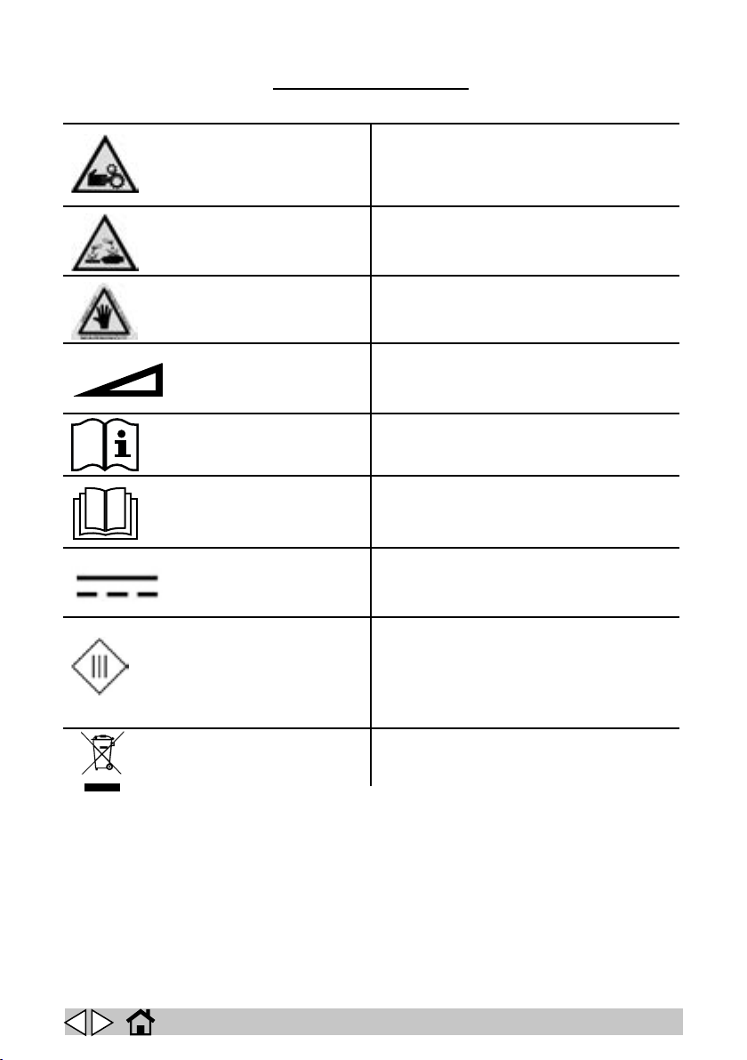
SAFETY SYMBOLS
WARNING! RISK OF ENTANGLEMENT
WARNING! RISK OF ACID BURNS
WARNING! RISK OF BURNS
MAXIMUM SLOPE
OPERATOR MANUAL, INSTRUCTIONS FOR USE
READ THE OPERATOR'S MANUAL
DIRECT CURRENT SYMBOL
CLASS III APPLIANCE. AN APPLIANCE IS IDENTIFIED
AS CLASS III WHEN ITS EXPLOSION-PROOF
PROTECTION IS BASED ON THE FACT THAT THERE
ARE NO VOLTAGES HIGHER THAN THE ULTRA-LOW
SAFETY EXTRA-LOW VOLTAGE (SELV). THIS MEANS
IN PRACTICE THAT THE APPLIANCE IS POWERED BY
A BATTERY OR A SELV TRANSFORMER.
SPECIAL WASTE. DO NOT DISPOSE OF AS NORMAL
WASTE.
EN
4

(Translation of original instructions)
INTRODUCTION / GENERAL
WARNINGS
This manual has been written by the
Manufacturer and is an integral part of the
machine1.
It denes the purpose for which the machine
has been designed and constructed and
contains all the information required by
operators2.
In addition to this manual, which contains
information for operators, other publications
are available providing specic information for
maintenance personnel3.
The terms “right” and “left”, “clockwise” and
“anti-clockwise” refer to the forward movement
of the machine.
Constant compliance with the instructions
provided in this manual guarantees the safety
of the operator and the machine, ensures
low running costs and high quality results
and extends the working life of the machine.
Failure to respect the instructions may lead to
damage to the operator, machine, oor and
environment.
To nd the topic that interests you more
quickly, see the list of contents at the beginning
of the manual.
INTRODUCTION
This instruction handbook contains guidelines
and practical information concerning the use,
adjustment and routine maintenance of your
new machine.
Your machine has been designed and built
to oer the best in terms of performance,
comfort and ease-of-use in a variety of dierent
conditions. Before delivery, your machine
has been checked at our factory and by our
dealer to guarantee that it is handed over to
you in perfect working order. To maintain the
machine in this condition and ensure problemfree operation, strictly follow the instructions
given in the handbook. Before attempting to
use the machine, read this handbook and
keep it to hand for any future consultation. For
further information regarding the machine, do
The denition "machine" replaces the trade name covered by this manual.
Persons responsible for using the machine without per-
forming any operations requiring precise technical skills.
Persons with experience, technical training and a knowledge of legislation and standards, able to perform all the
necessary operations and to recognise and avoid possible
risks in handling, installation, use and maintenance of this
machine.
not hesitate to contact your dealer, who has
competent maintenance sta, original parts
and the equipment needed to respond to your
needs.
NOTE: the machine version called DUAL
POWER refers to the model equipped with
an combustion engine and battery pack.
GENERAL SAFETY RULES
IMPORTANT: the following rules must be
carefully observed to avoid harm to the
operator and damage to the machine.
Carefully read the labels on the machine and
do not cover them for any reason; replace
them immediately if they are
damaged.
The storage temperature ranges from 0° to +
50°C.
The optimal working temperature should range
from 0° and + 40°C.
The ambient humidity must range from 0 to 95
%.
The machine must be kept indoors at all times.
The machine must be used exclusively by
operators trained in its use and/or who have
demonstrated their ability and have been
expressly authorised to use it.
The machine must not be used by minors.
Always pay attention to other people,
especially children, in the place where you are
working.
Children must be supervised to make sure they
do not play with the machine.
The machine is not intended for use by
persons (including children) with reduced
physical, sensory or mental capabilities, or lack
of experience and knowledge, unless they are
supervised by a person responsible for their
safety and have received instruction in the use
of the machine.
Do not inhale exhaust gases. Use the machine
indoors only when sucient ventilation can be
guaranteed and when there is another person
on stand-by, ready to assist in situations of
potential danger.
Do not bump against shelves or scaolding
when there is a risk of objects falling over.
In areas where the operator could be struck
by objects falling from overhead, do not use
the machine without a FOPS (Falling Object
Protective Structure)
Do not use the machine as means of transport.
Never use the machine to clean up ammable
or explosive liquids (e.g. petrol, fuel oil, etc.),
acids or solvents (e.g. paint solvents, acetone
EN
5

(Translation of original instructions)
etc.) even if diluted.
Never clean up burning or incandescent
objects.
Adapt the speed of the machine to the
conditions of adherence.
Avoid using the machine if its stability is not
guaranteed.
In the event of re, use a powder re
extinguisher, DO NOT USE WATER.
Do not use solvents or similar substances to
clean the machine.
Do not wash the machine by spraying directly
with water or using high pressure water jets.
Do not remove any guards that require the use
of tools to be removed.
NEVER use the machine without its guards
and safety systems. For your safety, make sure
all guards and safety systems are closed and
correctly mounted before starting the machine.
If you notice that the machine is not working
properly, make sure this does not depend on
failure to carry out the routine maintenance
operations. If this is not your case, contact
anauthorised service centre.
Always use the battery charger supplied by
the manufacturer, or alternatively, a charger
bearing the CE mark and certied by a third
party body in accordance with the latest edition
of the pertinent standard (EN 60335-2-29).
The charger must be equipped with double
or reinforced insulation between input and
output and with a SELV type output circuit with
maximum 24V output voltage.
Make sure the battery charger is compatible
with the batteries to be charged.
Make sure that the power socket used for the
battery charger is connected to a suitable earth
system and protected by thermal overload and
residual current circuit breakers.
Make sure the electrical characteristics of the
battery charger (voltage, frequency, absorbed
power) given on the rating plate are the same
as those of the mains power supply.
Check the battery charger power cable
regularly for damage. If the power cable is
damaged, do not use the charger.
If replacing parts, order ORIGINAL spare parts
from an authorised dealer or reseller.
Maintenance operations on the electrical
circuit and in any event all other operations
not explicitly described in this operating
manual must be performed by maintenance
personnel only, in compliance with current
safety regulations and as indicated in the
maintenance manual.
Always disconnect the power supply to the
machine before carrying out any maintenance.
Every 200 hours of work, have the machine
checked by an authorised service centre.
The product is classied as WEEE type special
waste and is covered by the requisites of the
new environmental protection regulations
(2002/96/EC WEEE). It must be disposed of
separately from ordinary waste in compliance
with current legislation and standards.
MODIFICATIONS AND
IMPROVEMENTS
Our company aims to constantly improve its
products, and consequently reserves the right
to make any changes and improvements when
deemed necessary, without having to apply
such to any machines sold previously.
SAFETY
You too can help avoid accidents.
No accident prevention program can be
eective without the full cooperation of the
operator directly responsible for operation of
the machine.
Most accidents that occur in a company, during
work or transport are caused by failure to
observe the basic rules concerning safety.
A careful and prudent operator is the best
guarantee against accidents and proves more
eective than any prevention program.
During work, pay attention to the persons
standing in the area to clean, especially
children.
EN
6
(Translation of original instructions)
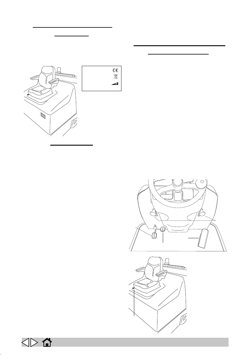
SERIAL NUMBER – CE
MARKING
Make sure that the machine is equipped with a
rating plate showing the serial number and CE
mark, positioned as shown in (g. 1). If this is
not the case, notify the dealer immediately.
Model :
Ser.N :
Vac :
Date :
W :
IP :
A :
Kg :
Hz :
g. 1
machine operation; assemble as described in
the chapter “REPLACING/INSTALLING THE
SIDE BRUSHES”.
THE CONTROLS AND THE
CONTROL PANEL
• Brake lock pedal and service brake pedal
(g. 2, ref. 1).
• Raise ap pedal (g. 2, ref. 2), pressing
this allows the centre brush to pick up
bulky objects.
• Accelerator pedal (g. 2, ref. 3).
• Right side brush control lever (g. 2, ref.
4), used to lower or raise the side brush.
• Left side brush control lever (g. 2, ref.
4A), used to lower or raise the side brush.
• Seat adjustment lever (g. 2, ref. 5).
Unpack your machine with great care, avoiding
UNPACKING
any manoeuvre that could lead to damage.
Once you have unpacked it, make sure all
parts are in a good condition. If you notice
any damage, DO NOT use the machine and
contact your retailer immediately.
Due to packaging and transport requirements,
some parts and optionals may be supplied
separately; for correct assembly, follow
the instructions given in the corresponding
chapters of this booklet.
Contents of the package
• Side brush
• Ignition key
• User and maintenance manual
Declaration of conformity
• Warranty coupon
• Batteries (if required)
Battery connection kit
• Battery charger (if required)
• For the Dual Power version, combustion
engine user manual.
If you notice that any of the above are missing,
contact your retailer immediately.
NOTE: To avoid losing it during transport,
the ignition key is placed inside the bag
containing the technical documents.
Make sure the packaging materials (bags –
cartons – pallets – hooks – etc.) are put away,
out of the reach of children.
To simplify transport, the side brush/brushes
are not mounted in the position intended for
4-4A
1
3
2
5
g. 2
EN
7

(Translation of original instructions)
1
2
• Display button, selects the data shown on
the display (g. 3, ref. 1).
• Display (g. 3, ref. 2):
• Button P1, select work program 1 (g. 3,
ref. 3).
• Button P2, select work program 2 (g. 3,
ref. 4).
• Button P3, select work program 3 (g. 3,
ref. 5).
• Filter shaker activation button (g. 3, ref.
6):
• Suction activation button (g. 3, ref. 7):
• Knob for adjusting the speed of the side
brushes (g. 3, ref. 8).
• Combustion engine start/stop button (g.
3, ref. 9).
• Ignition key (g. 3, ref. 10):
• Horn button (g. 3, ref. 11):
• Light switch (g. 3, 12) OPTIONAL.
• Emergency button (g. 3, ref. 13):
• Knob for adjusting the maximum speed
(g. 3, ref. 14).
• Drive board alarm indicator light; the
frequency at which the LEDs light up
indicates the error code. In the absence of
malfunctions, the status LED is on steady
while the machine is operating (g. 3, ref.
15).
• Machine direction selector (g. 3, ref. 16).
• Raise bin control button (g. 3, ref. 17).
• Lower bin control button (g. 3, ref. 18)
• Tip bin control button (g. 3, ref. 19)
• Fuel reserve indicator light (g. 3, ref. 20)
• Oil alarm indicator light (g. 3, ref. 21)
• Button for raising, lowering and tipping the
bin (g 3, ref. 22).
14 15
11
4
3
6
7
8 17 18 19
12
21
5
13
START
OFF
20 9 10
22
O
FF
N
O
g. 3
PREPARING THE MACHINE
IMPORTANT: Competent battery specialists
should preferably be contacted to choose
and install the new batteries.
Two dierent types of battery may be installed
on these machines:
• Leak-proof tubular batteries: these require
regular checks on electrolyte level. When
necessary, top up with distilled water until
the plates are covered. Do not over-ll (5
mm max. above the plates).
• Gel batteries: this type of battery requires
no maintenance.
Leak-proof tubular batteries are normally
supplied lled with acid and ready for use.
If the batteries in use are dry charged, they
must be activated before being installed in the
machine. Proceed as follows:
Remove the caps and ll all elements with
sulphuric acid solution specic for batteries
until the plates are entirely covered (this
requires at least a couple of passes for each
element).
Leave the batteries to stand for 4-5 hours to
16
EN
8

(Translation of original instructions)
DIESEL
allow air bubbles to come to the surface and
the plates to absorb the electrolyte.
Make sure the level of electrolyte is still
above the plates and if necessary top up with
sulphuric acid solution;
Close the caps.
Take special care when working with sulphuric
acid, as it is corrosive. Observe the following
precautions:
• Contact with the skin can cause irritation;
wash with soap and water.
• Inhalation of vapours can cause irritation
to the airways; stay out in the open air
and consult a doctor.
• Contact with the eyes can cause irritation;
ood the eyes with water immediately and
thoroughly for at least 15 minutes, and
consult a doctor.
Install the batteries in the machine (following
the procedure described below).
It is recommended to perform a rst top-up
before starting the machine; for this operation
see the chapter “BATTERY MAINTENANCE
AND CHARGING” and the battery instruction
booklet.
Lift the cowling toward the steering wheel of
the machine, and locate the batteries in the
compartment, positioning them as indicated in
the drawing (g. 4).
+12V
DIESEL
The electrical connection cables supplied
with the machine may be used to connect the
batteries.
IMPORTANT: in the battery compartment
on the DUAL POWER version equipped
with the DIESEL engine, there is a red wire
marked with the label “+ 12V”; this wire
must be connected to the +12V battery pole
(starter motor power supply).
With the batteries installed, plug the battery
connector into the machine (g. 5).
g. 5
NOTE: when the batteries are installed, set
the language to be used for the messages
shown on the display in the machine's
software menu; see the chapter “USER
MENU”.
NOTE: with the batteries installed, set the
type of battery selected in the machine’s
“TECHNICAL MENU”; contact the dealer.
For the combustion engine version, ll the fuel
tank: the type of fuel is specied on a label
near the fuel cap (g. 6).
g. 4
+12V
EN
g. 6
9

(Translation of original instructions)
Check the engine oil level (see the chapter
“COMBUSTION ENGINE MAINTENANCE”).
Climb onto the machine and adjust the seat as
desired (g. 7).
USING THE MACHINE
Insert the ignition key (g. 8), turn it clockwise:
the display will show all zeros for about 3
seconds, after which the battery voltage value
will be shown.
g. 7
BATTERY REMOVAL
IMPORTANT: when removing the batteries,
operators must use the necessary
equipment (gloves, goggles, protective
overalls, safety shoes, etc.) to limit the risk
of accidents.
Check that all the switches on the control panel
are in position “0” (o) and that the machine
is switched o, away from any naked ames;
do not short-circuit the battery poles, do not
cause sparks and do not smoke, and proceed
as follows:
• disconnect the battery wiring and bridge
terminals from the battery poles.
• if necessary, remove the devices xing
the battery to the base of the machine.
• lift the batteries from the compartment
using suitable lifting equipment.
IMPORTANT: When disposing of the
batteries, ensure compliance with local by-
laws or regulations.
STA R T
OFF
O
FF
N
O
g. 8
NOTE: in the operator’s seat is a safety
device that prevents drive (forward and
backward) when the operator stands up
from the seat.
NOTE: temporary activation of the indicator
lights on the console and of the horn is to
be considered normal.
Let at least three seconds pass after you have
turned o the machine, before turning it on
again.
Check the battery charge shown on the
machine’s display.
The display has two functions: Voltmeter and
Hour meter.
The voltmeter incorporates an undervoltage
shutdown function that automatically disables
all services except for drive when the battery
drops to a voltage of 20.5V (the BATTERY
DISCHARGED error code ashes on the
display).
In this case, recharge the battery (see the
chapter “BATTERY MAINTENANCE AND
CHARGING” and the battery user manual).
If the batteries are suciently charged, work
can now resume.
If the machine features a petrol engine, rst
start the engine.
EN
10

(Translation of original instructions)
STA R T
O
FF
O
N
IMPORTANT: DUAL POWER version
equipped with DIESEL engine, during
operation with the combustion engine o,
the “OIL ALARM” light remains on (g. 9);
this is normal.
g. 11
g. 9
IMPORTANT: the “OIL ALARM” indicator
light (g. 9) comes on when ignition is
started; on ignition the engine starts and
the indicator light goes o. If the light
comes on when driving, stop the machine
and check the engine oil level.
To start the combustion engine, push the
selector to the START position (g. 10), the
lever returns automatically.
STA R T
OFF
O
FF
N
O
g. 10
If the combustion engine does not start
immediately, the starter motor must not be
engaged for more than 5 seconds. This interval
can be repeated after a short rest period (about
8 - 10 seconds).
To stop the engine, turn the selector back
to the OFF position. In the event where
the alternator overheats, there is an
overtemperature protection device that stops
the machine; the “PAUSE MOTOR” error code
will be shown on the display
To start the machine, select forward or reverse
gear using the selector (g. 11).
NOTE: if needing to push the machine
when o or without the batteries, turn the
appropriate key to disengage the electric
drive motor; this will disable the machine’s
automatic braking function (g. 12).
g. 12
AUTO-POWER ON/OFF
The machine is equipped with an automatic
system for switching the functions on or o.
Selecting one of the three work programs, P1,
P2 or P3 temporarily activates the following
functions: centre brush, suction, side brushes;
the LED for the selected program lights up
together with the centre brush LED.
If the accelerator pedal is not pressed, after
a few seconds the functions will stop and the
LEDs will start ashing: the machine is now in
AUTO-POWER-OFF mode.
All of the functions are automatically
reactivated whenever the operator presses the
accelerator pedal.
By releasing the accelerator, all the functions,
except for the combustion engine, are
automatically deactivated.
NOTE: the “AUTO-POWER ON/OFF” system
can be disabled in the machine’s software
menu; see the chapter “USER MENU”.
EN
11

(Translation of original instructions)
STA RT
O
FF
O
N
START
OFF
O
FF
O
N
WORKING
IMPORTANT: do not inhale exhaust gases.
Use the machine indoors only when
sucient ventilation can be guaranteed and
when there is another person on stand-by,
ready to assist in situations of potential
danger.
IMPORTANT: the machine must only be
used on dry surfaces.
IMPORTANT: in areas where the operator
could be struck by objects falling from
overhead, do not use the machine without a
FOPS (Falling Object Protective Structure)
IMPORTANT: do not drive the machine with
the bin raised, except when approaching or
moving away from the garbage container.
Once the machine has been switched on and,
if necessary, after starting the combustion
engine, select the most suitable of the three
work programs for cleaning by pressing one of
the three buttons.
BUTTON P1 (light interior cleaning of quartz
concrete, smooth oors, etc.) (g. 13).
BUTTON P2 (cleaning carpets or other
surfaces) (g. 13).
BUTTON P3 (heavy exterior cleaning, asphalt
or uneven surfaces with large debris, etc.) (g.
13).
NOTE: the working parameters for
programs 1 - 2 - 3 are preset by the
manufacturer; to change the values contact
the dealer.
Lower the left and/or right side brush by pulling
the appropriate levers up or down (g. 15).
NOTE: the respective left and/or right
indicator light will light up on the control
panel.
NOTE: a resettable fuse is tted above
each side brush lever. If a side brush stops
working, press the button to reset the fuse
(g. 15).
To return the side brushes to the OFF position,
lift the two levers upwards.
OFF
SIDE
BRUSH
ON
g. 15
The speed of the side brushes can be adjusted
by turning the knob (g. 16).
g. 16
g. 13
Adjust the maximum drive speed according to
the working conditions by turning the knob (g.
14).
g. 14
The machine is equipped with an emergency
stop button (g. 17); pressing this button
immediately stops all the functions of the
combustion engine. To reactivate the machine,
release the button, then activate the desired
functions.
g. 17
EN
12

(Translation of original instructions)
If needing to work on wet ground, in order to
protect the paper lters, it is essential to stop
the suction motor by pressing the suction
button (g. 18).
g. 18
When work is nished, deselect the work
program used (1-2-3) and switch o the
combustion engine by moving the lever to the
OFF position.
Before leaving the machine, make sure that
the side brushes are raised from the oor, the
parking brake is engaged and that the ignition
key has been take out of the instrument board.
FURTHER PERFORMANCES
OF THE MACHINE
FEATURING AN ENGINE
The version featuring an engine can guarantee
the same working eciency even when the
motor is o, for instance when the fuel has run
out or when working in closed environments.
Operating autonomy in this case will depend
on the capacity of the batteries installed, on the
intensity of the chosen work program and on
initial battery charge.
To guarantee the working life of the batteries,
the machine features some safety systems:
• when the battery voltage drops below
20.5 volts, all of the functions except
for drive are automatically stopped.
When this situation occurs, recharge the
batteries or turn on the engine.
• Protection against battery overcharging:
this machine, having a current generator
with an electronic circuit that acts as a
voltage regulator, ensures the batteries
are correctly charged without damaging
them due to excessive load.
When the batteries are fully charged,
this system automatically ensures no
additional charge will be applied.
Based on tests carried out in the eld and
the results obtained on the energy balance of
our hybrid system (DUAL POWER system),
this can work in complete autonomy without
the need to stop the machine and externally
recharge the battery pack. Repeated tests
with the three work programs (P1, P2, P3) on
asphalted surfaces and with normal working
slopes have demonstrated that the machine
operates in complete autonomy.
However, being the machine designed also for
heavy duty working conditions (slopes of over
20%, extremely rough surfaces to clean), the
batteries may need to be recharged.
In this case, it is advisable to use an electronic
battery charger with a specic charge curve for
the batteries installed.
EN
13

(Translation of original instructions)
EMPTYING THE DEBRIS BIN
NOTE: to unload the debris bin, hold the
control button, then choose the desired
function.
• press the raise bin control button (g. 19).
• move alongside the garbage container.
• press the tip bin button (g 19).
NOTE: if the tip bin button is released, the
bin will return to the horizontal position.
NOTE: the machine is equipped with a
safety device that prevents the bin from
rotating before reaching a safe distance
from the machine.
• move away from the garbage
container, then lower the bin.
CLEANING AND SERVICING
THE FILTER
The suction lter makes a major contribution to
the eciency of the whole machine.
Proper lter maintenance will allow you
to obtain the best performance from your
machine.
The suction lter can be cleaned as follows:
• using the automatic cleaning system;
selecting the work program (P1-P2-P3)
the machine is programmed for automatic
and cyclical cleaning of the lter at predened intervals.
NOTE: automatic cleaning can be enabled/
disabled in the machine’s software menu;
see the chapter “USER MENU”.
• using the manual cleaning system; press
the lter shaker button (g. 20) and hold
it down for a few seconds. Repeat this
g. 19
g. 20
operation 4 or 5 times while using the
machine.
This operation should be performed at the
end of every working cycle. If the machine
is used in a dusty environment (e.g.
sawmills, warehouses where vehicles
operate, etc.), make sure to use the lter
shaker more frequently.
• manually cleaning the lter; if the lter
shaker is not eective in cleaning the
lter, and in any case every 20 operating
hours, clean the lter manually. Before
carrying out any type of work on the
machine, make sure that it is switched
o and that all of the functions are
EN
14

(Translation of original instructions)
deactivated. To do this, turn the key switch
to the OFF position.
• remove the back panel from the
machine (g. 21).
• remove the two lters from their
seat by turning locking restraining
handles (g. 21).
• blow the lter clean with compressed
air (maximum pressure 6 bars).
• reassemble the two lters.
• close the back panel.
REPLACING/INSTALLING
THE SIDE BRUSHES
To facilitate transport, the side brush (or
brushes) is not tted in its expected working
position. To install the side brush in the correct
position, proceed as follows:
• move the side brush control lever to the
up position.
• unscrew the screw on the side brush
motor shaft.
• remove the key protector.
• position the brush complete with ange on
the shaft.
• tighten the brush locking screw again (g.
22).
To replace worn side brushes, carry out the
operations listed above.
g. 22
g. 21
EN
15

(Translation of original instructions)
REPLACING THE CENTRE
BRUSH
IMPORTANT: this operation must be
performed with the machine switched o
and the key removed..
This machine features a system for
automatically adjusting the pressure exerted
and compensating for wear.
The need to replace the centre brush is
indicated by the BRUSH WORN code on the
display.
To replace the centre brush, proceed as
follows:
• Unscrew the knob and open the
door on the left of the machine (g.
23).
• Unscrew and remove the three
knobs xing the brush compartment
cover (g. 23).
• Remove the cover of the brush
compartment.
• Remove the worn brush (g. 24).
• Remove the adapter from the core
of the old brush and t it to the
new brush, taking care to keep the
bristles aligned in the same direction
(g. 24).
• Fit the new brush and make sure
that the adapter is inserted on the
drive hub.
• Replace the brush compartment
cover, following the dismantling
operations in reverse order.
g. 23
g. 24
BATTERY MAINTENANCE
AND CHARGING
IMPORTANT: the use of an unsuitable
battery charger can lead to dangerous
situations! If in doubt, contact your local
dealer.
IMPORTANT: make sure the battery charger
is compatible with the batteries to be
charged.
IMPORTANT: Check the electrolyte level
inside the leak-proof tubular batteries:
every 30 hours for the battery version, and
every week for the version with combustion
engine. If necessary top up with distilled
water.
The level of electrolyte is indicated in the
battery instruction handbook.
After you have lled the battery, close the
cells with their caps and clean the top
surface.
The battery compartment is located under the
operator’s seat.
The battery is a sealed unit and guaranteed
safe under normal circumstances; in the
unlikely event of uid leaking from the battery,
do not touch the uid and be sure to take the
following precautions:
• Contact with the skin can cause irritation;
wash with soap and water.
• Inhalation of vapours can cause irritation
to the airways; stay out in the open air
and consult a doctor.
• Contact with the eyes can cause irritation;
ood the eyes with water immediately and
thoroughly for at least 15 minutes, and
consult a doctor.
When necessary, recharge the batteries
according to the following instructions:
IMPORTANT: only recharge in a well-
ventilated area.
• the machine must be switched o and the
key removed.
• lift the cowling.
• unplug the battery connector from the
machine (g. 25).
EN
16

(Translation of original instructions)
• open all the cell (or element) covers on
the batteries (leak-proof tubular batteries).
• plug the battery connector into the
charger (g. 26).
• connect the battery charger to the mains.
• after charging, disconnect the batteries
from the battery charger and reconnect
them to the machine.
• close all the caps (leak-proof tubular
batteries) and clean the top surface of the
batteries.
ADJUSTING THE SIDE BRUSHES FOR WEAR
If the side brushes (when lowered) do not
touch the oor due to wear, they can be
adjusted as follows:
• Move the side brush to the working
position.
• Loosen the two adjustment screws
underneath the brush levers (g. 27).
• Manually move the brush to the required
position.
• Tighten the adjustment screws.
OFF
SIDE
BRUSH
ON
g. 25
24V
g. 26
EN
g. 27
17

(Translation of original instructions)
ADJUSTING THE BRAKE
When the eect of the service or parking brake
action is too weak, it can be adjusted using the
register “A+B”(g. 28).
A
B
g. 28
screws.
Gain access to the oil drainage pipe.
Remove the dipstick to check the engine oil
level.
Take the cap o the drainage pipe and let the
exhaust oil drain out.
NOTE: it is recommended to drain the oil
when the engine is hot.
Add the amount of new oil specied in the
engine user and maintenance manual. We
recommend only SAE 15/40 multigrade oil,
which guarantees good engine lubrication at
temperatures from -15°C to over 40°C (g. 30).
COMBUSTION ENGINE
MAINTENANCE
NOTE: in addition to carefully reading the
combustion engine user and maintenance
manual, below are some practical tips.
Check the engine oil level at least once a week
using the dipstick (g. 29); for topping up, use
the oil specied below.
g. 29
The engine oil must be changed the rst time
after 20 operating hours, or in any case after
no more than 1 month.
Subsequently, every 100 hours, or at most
every 8 months.
To replace the oil in the engine, proceed as
follows:
Remove the side sump on the right-hand
side of the machine by unscrewing the xing
g. 30
AIR FILTER OF THE ENGINE
NOTE: in addition to carefully reading the
combustion engine user and maintenance
manual, below are some practical tips.
Periodically check the engine air lter, and
replace it when necessary.
Check and if necessary wash the sponge (pre-
lter) with water and soap or other household
detergent; wring it out and leave it to dry.
EN
18

(Translation of original instructions)
“CHANGE OIL” ALARM
CODE
The CHANGE OIL error code tells the operator
to change the combustion engine oil every 100
operating hours (only active on combustion
engine versions). Pressing the display button
once (g. 31) shows the partial operating hour
counter for the combustion engine.
This is a four-digit display: the rst digit on the
left (0-9 range) and the three remaining digits
display the actual hours of work of the engine.
When having reached 100 operating hours, the
machine shows the “CHANGE OIL” message
ashing on the display, telling the operator
to change the engine oil (see the chapter
“COMBUSTION ENGINE MAINTENANCE”).
After having changed the engine oil, reset the
hour counter as follows:
• press the display button twice to view the
partial operating hour counter.
• press the display button again and hold it
for at least 5 seconds (the machine partial
operating hour counter will be reset). The
rst digit on the display increases by one
unit, so that the operator will know how
many times oil has been replaced.
NOTE: if the engine oil is not changed,
every time the machine is switched on
again, the operator will hear a sound
emitted by the horn ve times, and the
“CHANGE OIL” message will ash on the
display. The “CHANGE OIL” message can
be cleared by pressing the display button.
g. 31
EN
19

(Translation of original instructions)
IMPORTANT: this operation must be performed with the machine switched o and the key
MAINTENANCE OF THE BATTERY VERSION
removed..
All routine or special maintenance must be performed by competent personnel or at an
authorised service centre.
NOTE: battery life depends on regular maintenance (check electrolyte level and density in
leak-proof tubular batteries). If the machine is not used for a long time (for example, 4 to
6 weeks) the batteries will need to be recharged in order to ensure that the voltage never
falls below the threshold of 20.5 V; in fact unused batteries suer from the self-discharge
phenomenon.
A : On receipt
B : Every 30 hours
C : Every 50 hours
D: Every 100 hours
E : Every 400 hours
CHECK A B C D E
Battery liquid and
voltage levels
Check the brushes (or
carbon brushes) on all
of the electric motors
and replace if worn
□
□
or every
two weeks
□
Tightness of the belts □ □
Brake adjustment □ □
Tightness of the nuts
and screws
State of the side brush
Panel lter cleaning □
Tightness of the bin,
lter, ap gaskets
□ □
EN
□
□
20

(Translation of original instructions)
IMPORTANT: this operation must be performed with the machine switched o and the key
COMBUSTION ENGINE VERSION MAINTENANCE
removed..
All routine or special maintenance must be performed by competent personnel or at an
authorised service centre.
For all maintenance on the combustion engine, see the instruction manual.
NOTE: battery life depends on regular maintenance (check electrolyte level and density in
leak-proof tubular batteries). If the machine is not used for a long time (for example, 4 to
6 weeks) the batteries will need to be recharged in order to ensure that the voltage never
falls below the threshold of 20.5 V; in fact unused batteries suer from the self-discharge
phenomenon.
A: On receipt
B: Twice a week
C: Every week
D: Every 20 hours
E: Every 50 hours
F: Every 100 hours
G: Every 150 hours
H: Every 300 hours
I: Every 400 hours
CHECK A B C D E F G H I
Battery liquid and voltage levels □ □
Clean the engine air lter □
Panel lter cleaning □
Oil and engine □ □
Change engine oil, petrol version
1st
time
□
Change engine oil, diesel version
Check the brushes (or carbon
brushes) on all of the electric
motors and replace if worn.
Tightness of the belts □ □
Brake adjustment □ □
Tightness of the nuts and screws □
State of the side brush □
Tightness of the bin, lter, ap
gaskets
□ □
EN
1st
time
□
21
□

(Translation of original instructions)
TROUBLESHOOTING TABLE
Error code Machine behaviour Description of the
problem
PAUSE MOTOR Drive stops Drive motor
overtemperature >
95°C, or alternator
overtemperature >
150°C
Possible solution
If having driven up a
slope this may can be
normal, let the motor
cool down for 20
minutes.
Check that the cooling
fan is working
Check that the brake
is not locked.
Check that the front
wheel turns freely.
PAUSE DRIVE Drive stops Electronic
BRUSH CURRENT The working functions
CHANGE OIL This is only shown if
BATTERY RESERVE This is simply a
BATTERY
DISCHARGED
are disabled
the machine has a
combustion engine
warning that the
battery charge is
getting low
The machine’s
functions are stopped,
excluding drive
control circuit
overtemperature >
85°C
Excess current or
centre brush blocked
It is activated after 99
operating hours
It is shown when the
battery voltage falls
below 21.3V
If the voltage read
falls below 20.3V
for 3 seconds
consecutively
If the air temperature
is high, stop the
machine for 20
minutes, then start
again. If the problem
remains, contact a
service centre.
Check free brush
movement or for
the presence of any
impediments (ropes,
plastic and so on)
It warns the operator
to change the engine
oil (to reset it, press
the display button
for 5 seconds while
the hour counter is
displayed)
No action needed,
except to charge the
battery
Charge the battery
EN
22

(Translation of original instructions)
BATTERY
EXHAUSTED
BRUSH WORN The machine
The machine stops If the voltage read
continues working
falls below 18V
for 3 seconds
consecutively
The brush is no
longer able to apply
pressure to the oor
because it is worn
Charge the battery
Replace the centre
brush
EN
23

(Translation of original instructions)
If drive is interrupted, the error code can be identied by means of the status LED. In the absence
DRIVE BOARD ALARMS
of malfunctions, the status LED is steadily on while the machine is in operation. If a malfunction is
detected, the status LED provides two types of information, a slow ash (2 Hz) or a rapid ash (4
Hz) to indicate the severity of the malfunction.
Malfunctions with a slow ash are cancelled automatically once the malfunction has been repaired
and the machine functions normally again. Malfunctions with a rapid ash ("*" in the table) are
considered more serious. The machine must be turned o to reset operation after repairing the
malfunction.
The indication of severity remains active for 10 seconds, after which the status LED ashes
constantly showing a two digit malfunction code until the repairs have been carried out.
For example, error code "1,4" is displayed as follows:
□ □ □ □ □ example alarm code 1,4
LED CODES DESCRIPTION
1,1 □ □ Drive motor output malfunction - Overcurrent error
1,2 □ □ □ EEPROM malfunction, main contactor malfunction,
1,3 □ □ □ □ NOT USED
1,4 □ □ □ □ □ NOT USED
2,1 □ □ □ Incorrect machine start up sequence (with key)
2,2 □ □ □ □ Incorrect machine start up sequence (with key)
2,3 □ □ □ □ □ Incorrect start up sequence for more than ve seconds
2,4 □ □ □ □ □ □ Malfunction of speed limiter potentiometer on control
3,1 □ □ □ □ NOT USED
3,2 □ □ □ □ □ NOT USED
3,3 □ □ □ □ □ □ Accelerator pedal malfunction
3,4 □ □ □ □ □ □ □ NOT USED
4,1 □ □ □ □ □ Battery voltage too low (voltage < 21 V)
4,2 □ □ □ □ □ □ Battery voltage too high (voltage > 48 V)
4,3 □ □ □ □ □ □ □ Drive motor > 80°C thermal cutout tripped
4,4 □ □ □ □ □ □ □ □ NOT USED
malfunction of board components, incorrect drive motor
voltage.
panel
EN
24

(Translation of original instructions)
Enter the menu by pressing and holding the display button for 5 seconds while the machine is on,
USER MENU
but with no active function.
Pressing button P1 increases the value of the selected variable.
Pressing button P3 decreases the value of the selected variable.
Pressing the display button, the set data is saved and the next item is displayed.
Exit the menu by pressing and holding the display button for 5 seconds.
1. LANGUAGE, language setting parameter.
2. PROG.1, brush pressure P1 parameter. Default value 020.
3. PROG.2, brush pressure P2 parameter. Default value 040.
4. PROG.3, brush pressure P3 parameter. Default value 060.
5. POWER OFF, enables/disables the AUTO-POWER ON/OFF system. Default value YES.
6. RAISE BRUSH, enables/disables lifting of the centre brush in reverse. Default value YES.
7. FILTER SHAKE, enables/disables automatic activation of the lter shaker and the activation
time. Default value 120”.
EN
25


IP Cleaning S.p.A.
Viale Treviso 63
30026 Summaga di Portogruaro
Venezia (Italy)
T: +39 0421 205511
F: +39 0421 204227
E: www.ipcworldwide.com
W: info@ipcworldwide.com
PLDC01969
Rev.03 (03-2019)
 Loading...