

Page 1
OPERATION MANUAL
PUBLIC ADDRESS SYS TEM
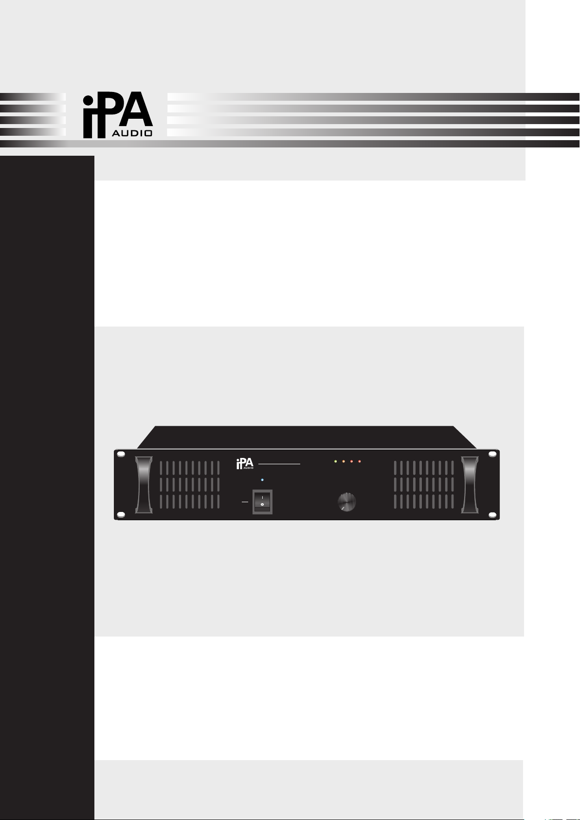
IPA-1C240
POWER AMPLIFIER
IPA -1C24 0
POW ER AMPL IFIER
POWER
ON
OFF
SIGNAL
2
3
1
CLIP
VOLUME
4 6
0
TEMP
PROT
5
7
8
9
10
Please follow the instructions in this manual to obtain the optimum results from this unit.
We also recommend that you keep this manual handy for future reference.
Page 2

TABLE OF CONTENTS
1. SAFETY PRECAUTIONS ........................................................................................ 3
2. GENERAL DESCRIPTION ..................................................................................... 5
3. FEATURES ............................................................................................................... 5
4. NOMENCLATURE AND FUNCTIONS
4. 1 Front Panel ..................................................................................................................6
4. 2 Rear Panel...................................................................................................................7
5. CONNECTIONS .........................................................................................................8
6. OPERATION GUIDANCE
POWER SWITCH & POWER INDICATOR
6. 1 ....................................................................... 9
PHONE JACK LINE INPUT AND XLR LINE INPUT
6. 2 ...........................................................9
XLR LINE OUTPUT
6. 3 .................................................................................................... 10
6. 4 POWER SUPPLY INPUT .............................................................................................10
6. 5 SPEAKER OUTPUTS 4~16¦& 70V& 100V.................................................................... 11
MACHINE OPERATION
7. ......................................................................................... 12
8. APPLICATIONS ...................................................................................................... 13
9. BLOCK DIAGRAM...................................................................................................14
10. SPECIFICATIONS .......................................................................... .....................15
11.DIMENSIONAL DIAGRAM .................................................................................. 16
2
Page 3
1. SAFETY PRECAUTIONS
Be sure to read the instructions in this section carefully before use.
Make sure to observe the instructions in this manual as the conventions of safety symbols and messages
regarded as very important precautions are included.
We also recommend you keep this instruction manual handy for future reference.
Safety Symbol and Message Conventions
Safety symbols and messages described below are used in this manual to prevent bodily injury and property
damage which could result from mishandling. Before operating your product, read this manual first and
understand the safety symbols and messages so you are thoroughly aware of the potential safety
Indicates a potentially hazardous situation which, if mishandled, could
result in death or serious personal injury.
Indicates a potentially hazardous situation which, if mishandled, could
result in moderate or minor personal injury, and/or property damage.
When Installing the Unit
Do not expose the unit to rain or an environment
where it may be splashed by water or other liquids,
as doing so may result in fire or electric shock.
Use the unit only with the voltage specified on the
unit. Using a voltage higher than that which is
specified may result in fire or electric shock.
Do not cut, kink, otherwise damage nor modify the
power supply cord. In addition, avoid using the
power cord in close proximity to heaters, and never
place heavy objects -- including the unit itself -- on
the power cord, as doing so may result in fire or
electric shock.
Be sure to replace the unit's terminal cover after
connection completion. Because high voltage is
applied to the speaker terminals, never touch these
terminals to avoid electric shock.
Be sure to ground to the safety ground (earth)
terminal to avoid electric shock. Never ground to a
gas pipe as a catastrophic disaster may result.
When the Unit is in Use
Should the following irregularity be found during
use, immediately switch off the power, disconnect
the power supply plug from the AC outlet and
contact your nearest dealer. Make no further
attempt to operate the unit in this condition as this
may cause fire or electric shock.
If you detect smoke or a strange smell coming
from the unit.
If water or any metallic object gets into the unit
If the unit falls, or the unit case breaks
If the power supply cord is damaged (exposure of
the core, disconnection, etc.)
If it is malfunctioning (no tone sounds.)
To prevent a fire or electric shock, never open nor
remove the unit case as there are high voltage
components inside the unit. Refer all servicing to
your nearest dealer.
Do not place cups, bowls, or other containers of
liquid or metallic objects on top of the unit. If they
accidentally spill into the unit, this may cause a fire
or electric shock.
IPA
IPA
Avoid installing or mounting the unit in unstable
locations, such as on a rickety table or a slanted
surface. Doing so may result in the unit falling
down, causing personal injury and/or property
damage.
Do not insert nor drop metallic objects or
flammable materials in the ventilation slots of the
unit's cover, as this may result in fire or electric
shock.
3
Page 4
SAFETY PRECAUTIONS
When Installing the Unit
Never plug in nor remove the power supply plug
with wet hands, as doing so may cause electric
shock.
When unplugging the power supply cord, be sure
to grasp the power supply plug; never pull on the
cord itself. Operating the unit with a damaged
power supply cord may cause a fire or electric
shock.
When moving the unit, be sure to remove its power
supply cord from the wall outlet. Moving the unit
with the power cord connected to the outlet may
cause damage to the power cord, resulting in fire or
electric shock. When removing the power cord, be
sure to hold its plug to pull.
Do not block the ventilation slots in the unit's cover.
Doing so may cause heat to build up inside the unit
and result in fire.
Avoid installing the unit in humid or dusty locations,
in locations exposed to the direct sunlight, near the
heaters, or in locations generating sooty smoke or
steam as doing otherwise may result in fire or
electric shock.
When the Unit is in Use
Do not place heavy objects on the unit as this may
cause it to fall or break which may result in
personal injury and/or property damage. In
addition, the object itself may fall off and cause
injury and/or damage.
Make sure that the volume control is set to
minimum position before power is switched on.
Loud noise produced at high volume when power is
switched on can impair hearing.
Do not operate the unit for an extended period of
time with the sound distorting. This is an indication
of a malfunction, which in turn can cause heat to
generate and result in a fire.
Contact your dealer as to the cleaning. If dust
is allowed to accumulate in the unit over a long
period of time, a fire or damage to the unit may
result.
If dust accumulates on the power supply plug or in
the wall AC outlet, a fire may result. Clean it
periodically. In addition, insert the plug in the wall
outlet securely.
Switch off the power, and unplug the power supply
plug from the AC outlet for safety purposes when
cleaning or leaving the unit unused for 10 days or
more. Doing otherwise may cause a fire or electric
shock.
IPA
An all-pole mains switch with a contact separation of at least 3 mm in each pole shall be incorporated in
the electrical installation of the building.
Due to product upgrades, while some of the features and specification in the user manual does not
match the actual functions, sorry for any inconvenience and thanks for your kind understanding!
4
Page 5
2. GENERAL DESCRIPTION
This range of power amplifiers are designed for general commercial and industrial public address ap plications. Rack mount design in 2U type, rated power ranges 240W which provides a wide selection
to meet different size sound system needs. Both balanced and unbalanced line inputs make it selec table for installer, balanced line output feeds to another power amplifier as well as secures the signal
transmission is less noise and longer distance. 70V, 100V and 4-16ohm speaker outputs are conveni ent for installa tion when selection different speaker matching. A master volume control is included.
Complete protection includes clip, s hort circuit, high temp and overload. Indications for power,
signal, clip, protection and temp.
3. FEATURES
1. Rack mount amplifier in 2U type
2. Rated power 240W
3. 70V, 100V and 4~16ohm speaker outputs
4. solated transformer for human safety operation
5. Balanced XLR type line input and unbalanced 1/4 inch TRS phone jack line input
6. Balanced XLR type line output feeds to another power amplifier
7. Reliable protection of over heat, over load, clip & short circuit.
8. Indications for power, signal, clip, protection and temp
9. Excellent device of radiator cooling fanner that ensures working effectively.
10. GND/lift switch to have two options: earth line grounded or lifted
5
Page 6
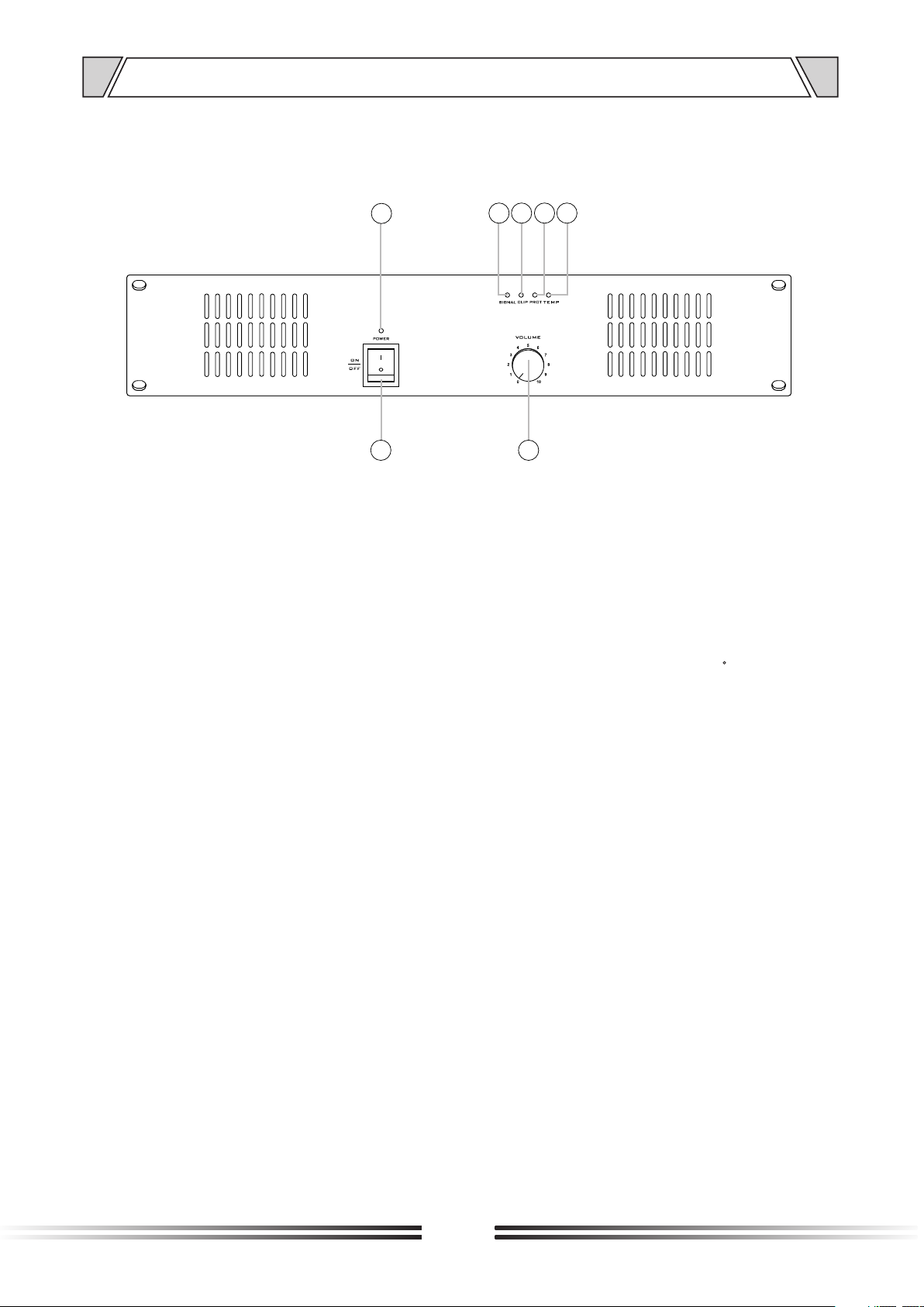
4. NOMENCLATURE AND FUNCTIONS
4.1 FRONT PANEL
56
7
1 2
1. POWER SW ITCH
On top of the opening PowerЈPress the end, power shut down
2. VOLUME
Channel volume control
3. TEMP
4
3
The protection indicator will be light on when the inside temperature is over 90C, the output
will be
cut to protect the amplifier from damage. It will resume to work after cooling down
4. PROT
The protection indicator will be light on when the constant output is 160% higher than the rated
output, the output will be cut to protection the amplifier from damage. This indicator will be
extinguished when amplifier is under normal working conditions.
5. CLIP
Clip lit when max wattage output & output signal distortion.
6. SIGNAL
Signal indicator LED When lit input signal is detected.
7. POWER
Power indicator LED
6
Page 7
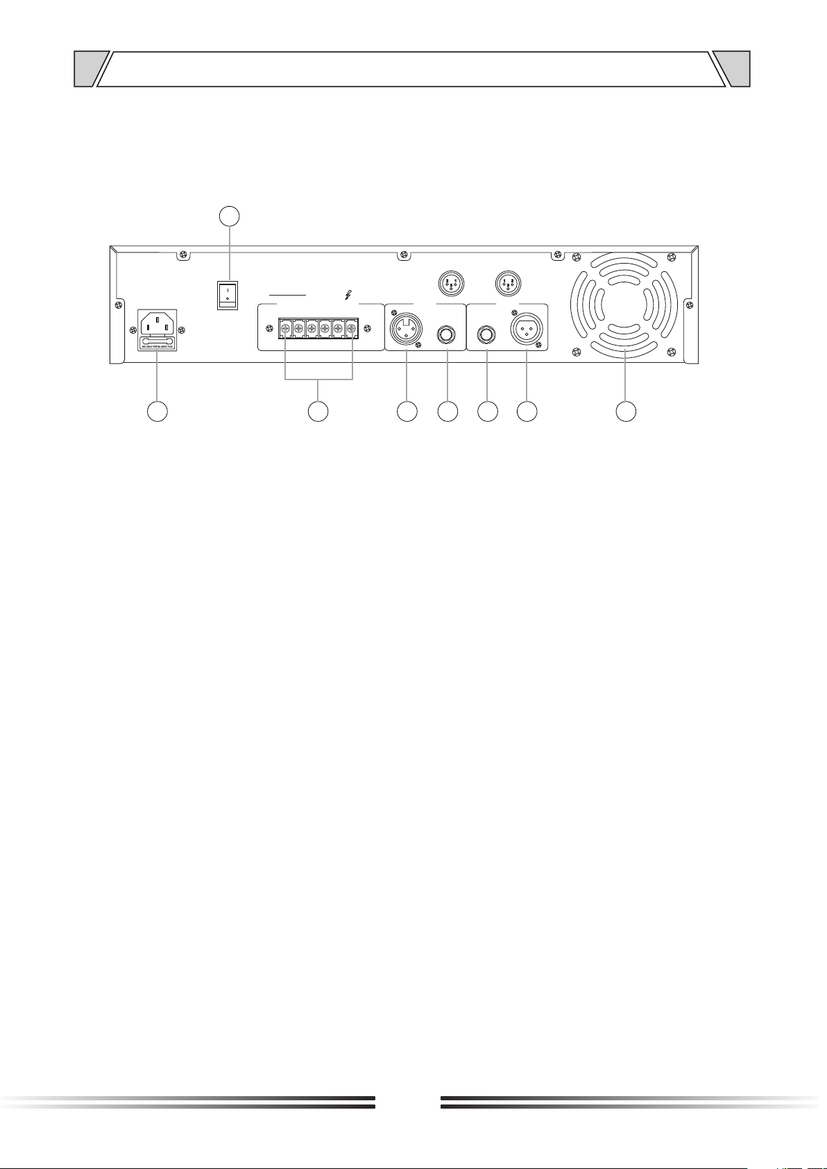
NOMENCLATURE AND FUNCTIONS
4.2 REAR PANEL
15
INP UTS LIN K
XLR BA L
1-GN D
GND
LIFT
COM COM
OUT PUTS
4-16 ¦
COM
70V 100 V
INPU TS LINK
12
3
2-HO T+
3-CO LD-
8 9 10 11 13 14
12
8. ~230V 50Hz P OWER INP UT
9. C OMMON SP EAKER OU TPUT
Connectors for 4 ohms or 70V and 100V
speaker
10. LINE IN PUT (XLR )
Music signal input balance
11. LINE INPUT (6.35TRS)
Balanced or unbalanced input music signal (unbalanced input, use of non-equilibrium
6.35TRS jack)
12. LINK OU TPUT (6. 35TRS)
Balanced or unbalanced output music signal (unbalanced output, use of non-equilibrium
6.35TRS jack)
13. LINE CASCADE OUTPUT (COR LEONE SO CKET)
XLR, output signal of power amplifier
14. FAN
Equipment, exhaust vents, equipment work properly, you must wrap the hole can not have any
object covered, to avoid overheating protection
15. GRO UND LIFTER
Earth line ground or lift switch. Enable the switch to "GND" position when one unit is used,
disable the switch "LIFT" when several units are used to avoid noise caused by several earth
line grounded.
7
Page 8
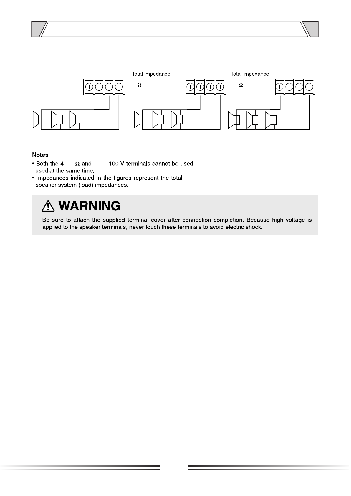
5. CONNECTIONS
SPEAKER C ONNECT IONS
100 V
70V
4~1 6¦ 100 V 70V
COM
20
(IPA-1C240)
100 V 70V 4~ 16¦
COM
(IPA-1C240)
42
4~1 6¦
COM
4~16¦ LIN E
4~16
70V/
70V LIN E
100V LI NE
8
Page 9
T-1S60
POWER AMPLIFIER
100V
70V
50V 4¦
COM
LINK
OUTPUTS
INPUTS
6. OPERATION GUIDANCE
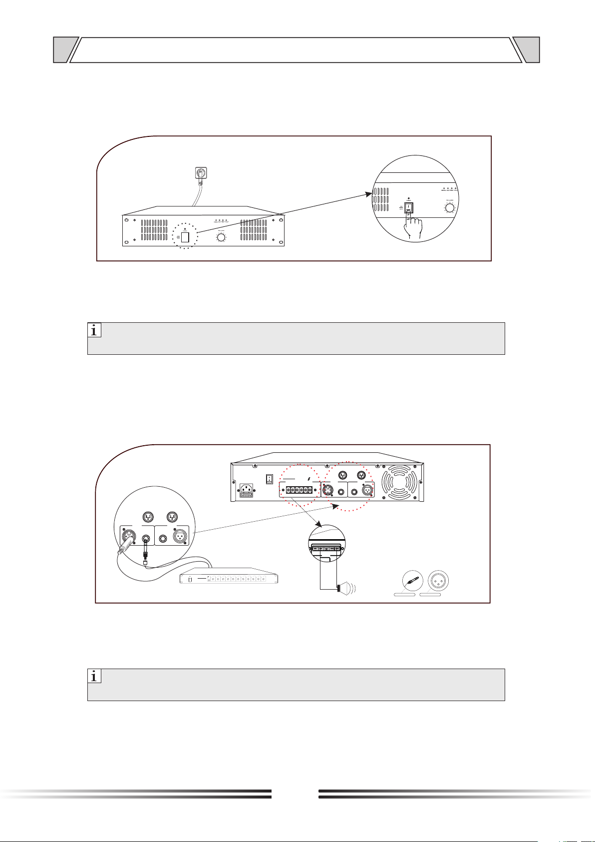
6.1 POWER S WITCH & PO WER INDI CATOR
Picture 1.1
Electricity power on when power switch is at ЎONЎ position and power indicator light in blue.
Electricity power off when power switch is at ЎOFFЎ position and power indicator extinguished.
Notice:
Please make sure amplifier operation is under well power supplied status. Please contact
professional technician from distributor for any repairment.
6.2 PHON E JACK L INE INP UT AND XLR LINE INPUT
INPUTS LINK
XLR BAL
1-GND
INPUTS LINK
12
3
-
+
2-HOT+
3-COLD-
70V,S peake r Outpu t
6.3mm phono jack
180 3-pole XLR
1 2
3
1 foot for t he grou nd
2 Signal H ot-si de (pos itive )feet
3 feet sig nal col d side (n egati ve)
INPUTS LINK
XLR BAL
1-GND
2-HOT+
3-COLD-
INPUTS LINK
12
3
POWER
PRE-AMPLIFIER
ON
OFF
1 CH Pr e-Amp lifie r
CHIME MIC1 MIC2 MIC3 MIC4 AUX1 AUX2 AUX3 BASS TREBLE MASTER
5
5
6
6
4
4
7
3
3
8
2
2
9
1
1
10
10
0
0
5
5
5
5
5
5
6
4
-10+1
6
6
6
6
6
4
4
4
4
4
7
3
-2
7
7
3
8
8
2
9
9
1
10
0
+2
7
7
7
7
3
3
3
3
8
2
-3
+3
8
8
8
8
2
2
2
2
9
1
-4
+4
9
9
9
9
1
1
1
1
10
0
+5-5
10
10
10
10
0
0
0
0
GND
OUTPUTS
4-16¦
70V 100V
COM
COM COM
LIFT
5
6
4
-10+1
7
3
-2
+2
8
2
-3
+3
9
1
-4
+4
10
0
+5-5
Picture 1.2
Both phone jack and XLR inputs are balanced. Both are one of your options for line signal inputs from pre
amplifier or mixer. The line output volume level is controlled by front panel knobs
Notice:
please minimum the volume knob to "MIN" position when line input is operated to avoid electricity
shock to the amplifier.
9
Page 10
OUTPUTS
COM 4-16¦ 70V 100VCOM COM
Ѕ Ё
РРµ»ЗОҐЇ
µЙ±·Й№ХКЈ·ЧТИФЗО
ЧРІ»ЈТГ·Йµ»К№Ў
ЧТ:
№ЦК±ВµЧУП№Л
№ЦК·ШЗВЖЅ
ВПґВПµТ№ТґC¶¶І
COM
GND
LIFT
РРµ»ЗОҐЇ
µЙ±·Й№ХКЈ·ЧТИФЗО
ЧРІ»ЈТГ·Йµ»К№Ў
ЧТ:
OPERATION GUIDANCE
6.3 XLR LINE OUTPUT
INPUTS LINK
XLR BAL
1-GND
GND
OUTPUTS
4-16¦
70V 100V
COM
COM COM
LIFT
INPUT S LINK
XLR BAL
1-GND
2-HOT+
3-COLD -
INPUTS LINK
12
3
Pow er Ampli fier
GND
OUTPUTS
LIFT
COM 4-16¦ 70V 1 00VCOM COM
-
+
Picture 1.3
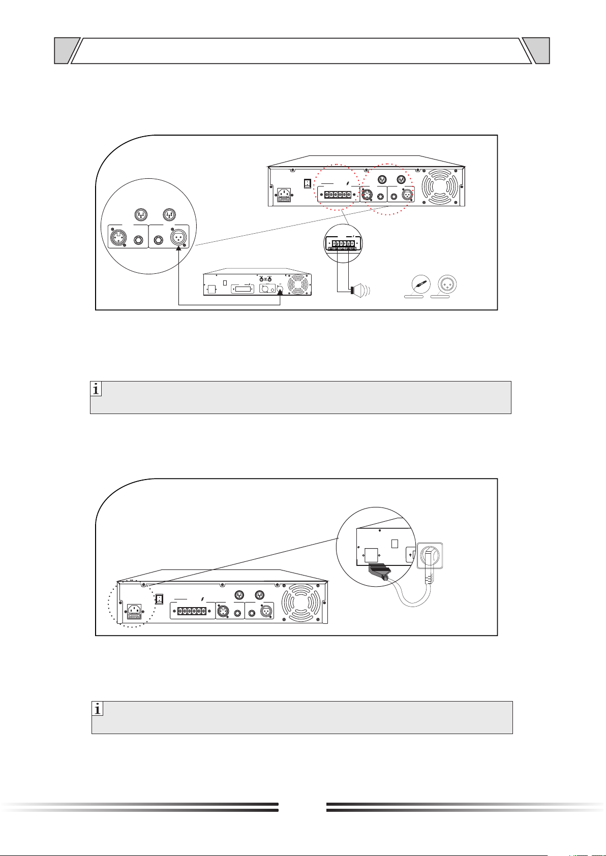
The XLR input is balanced. The line output could link another amplifier for more loudspeaker connection. The
line output volume level is controlled by front panel knobs.
2-HOT+
3-COLD-
INPUTS LINK
12
3
70V,S peake r Outpu t
6.3mm phono jack
180 3-pole XLS
1 2
3
1 foot for t he grou nd
2 Signal Hot -side ( posit ive)feet
3 feet sig nal col d side (n egati ve)
Notice:
please minimum the volume knob to "MIN" position when line output is operated to avoid electricity
°ИРЦ
shock to the amplifier.
6.4 POWER SUPPLY INPUT
INPUTS LINK
XLR BAL
1-GND
GND
OUTPUTS
4-16¦
70V 100V
COM
COM COM
LIFT
2-HOT+
3-COLD-
INPUTS LINK
12
3
Picture 1.4
Power electricity to supply power to this amplifier. Please make sure suitable AC voltage inputs by guidance
of this equipments silk printing and specifications. Take off the power cord when non-use
Notice: Please input only suitable AC voltage to avoid any burn and damage to the amplifier.
°ИРЦ
10
Page 11
OUTPUT S
COM 4-1 6¦ 7 0V 100VCOM C OM
Ѕ Ё
РРµ»ЗОҐЇ
µЙ±·Й№ХКЈ·Ч ТИФЗО
ЧРІ»ЈТГ·Йµ» К№Ў
ЧТ:
№ЦК±ВµЧУП№Л
№ЦК·ШЗВЖ Ѕ
ВПґВПµТ№ ТґC¶¶І
OUTPU TS
COM 4-1 6¦ 70V 10 0VCOM C OM
Ѕ Ё
РРµ»ЗОҐЇ
µЙ±·Й№ХКЈ· ЧТИФЗ О
ЧРІ»ЈТГ·Йµ »К№Ў
ЧТ:
№ЦК±ВµЧУП№Л
№ЦК·ШЗВЖ Ѕ
ВПґВПµТ№ ТґC¶¶І
OUTPU TS
COM 4-1 6¦ 70V 100 VCOM C OM
Ѕ Ё
РРµ»ЗОҐЇ
µЙ±·Й№ХКЈ· ЧТИФЗО
ЧРІ»ЈТГ·Йµ »К№Ў
ЧТ:
№ЦК±ВµЧУП№Л
№ЦК·ШЗВЖ Ѕ
ВПґВПµТ№ ТґC¶¶І
OPERATION GUIDANCE
6.5 SPEAKER OUTPUTS 4~16¦& 70V& 100V
INPUTS LINK
XLR BAL
1-GND
GND
OUTPUTS
4-16¦
70V 100V
COM
COM COM
LIFT
INPUTS LINK
12
3
2-HOT+
3-COLD-
-
+
4-1 6¦,SP EAK
70V,S PEAK
-
+
100 V,S PEAK
+
-
Picture 1.5
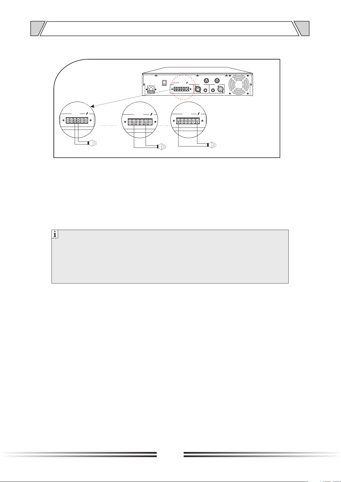
High impedance and low impedance both speaker output for different application use. Only choose one of the
positive end from 4~16¦& 70V& 100V, then connect the negative end"COM" and one the positive end to the
speaker's according ends. High impedance speaker output only for high impedance speaker connection and
low impedance speaker output only for low impedance speaker connection. Speaker total power output shall
be no higher than 80% percent of the amplifier rated power output.
Notice:
No mixing connected the positive and negative ends between the amplifier and loudspeaker.
Never allowed to use more than one output among 4~16¦/70V/100V.
Speaker continuous power output never higher than 80% of the amplifier rated power output.
Never connect high impedance output to low impedance speaker nor connect low impedance output to
high impedance speaker.
Please cover the speaker output ends after wiring to avoid any touch. The speaker output are high
voltage, never touch by human body to avoid electricity shock.
11
Page 12
7. MACHINE OPERATION
MIC INPUT C HANNEL 1~3
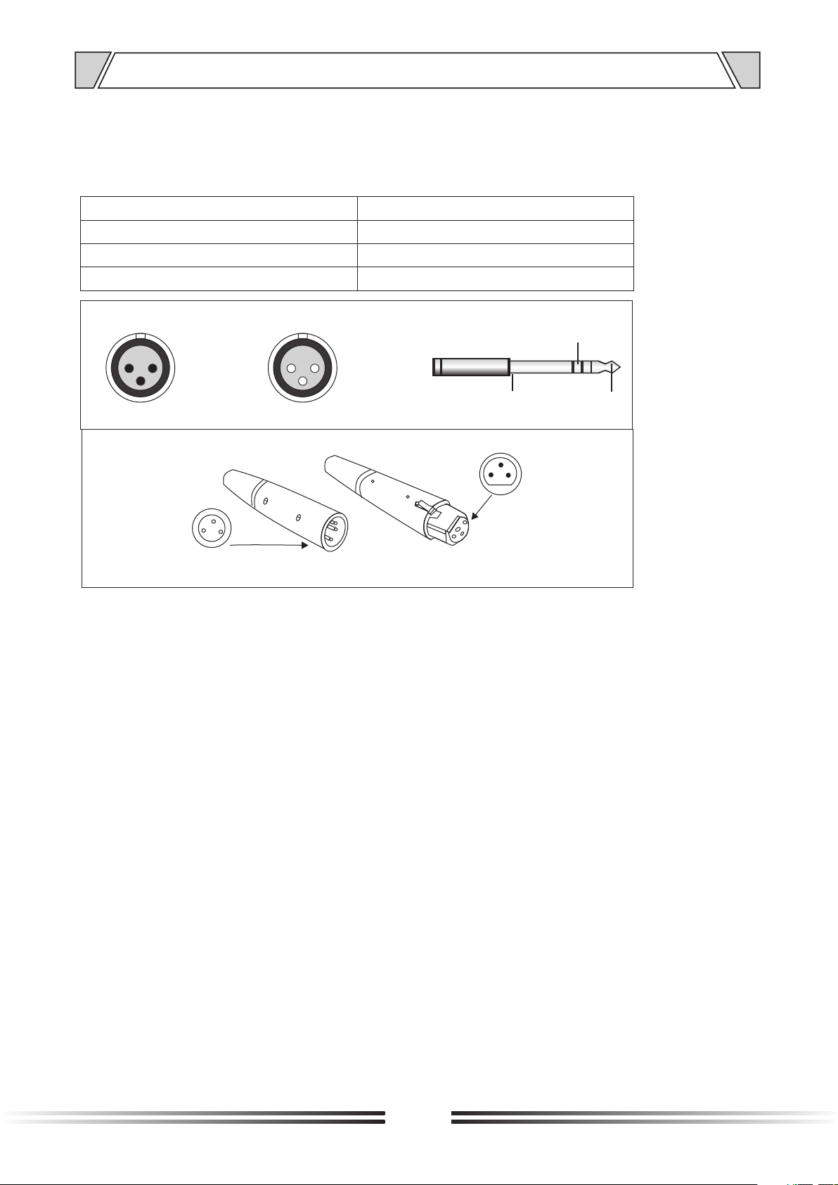
This is a special connector which will accept 3-conductor XLR.
These inputs are suitable to receive signal from microphones level devices.
MIC JACK (X LR JACK)
Pin 1:GROUND
Pin 2:HOT(+)
Pin 3:COLD(-)
1.GROUND
1
2
2.HOT
3
3.COLD
CH1/CH2 INPUTS
3
2
1
CH1/CH2 LINKS
CH1/CH2 LINKS
OPERATION ATTENTION
LINE JACK ( TRS PHON E JACK)
Sleeve:GROUND
Tip:HOT(+)
Ring:COLD(-)
1
2.HOT
3
3.COLD
GROUND
3
1
1.GROUND
2
COLD
HOT
2
CH1/CH2 INPUTS
=
It indicate signal distortion when the panel's CLIP
LED is lighting red and it may caused by:
1. If there is excess signal input, the power LED
will light, in this case, please turn signal to the
minimum.
2. There is overload output if the LED is not ligh ting, please check the input circuit.
=
When you start the machine, it will run into auto checking condition, its protection LED (yellow)
will shine 3 seconds. If the protection time is too
long, please check the machine or contact with
our distribution of your local place.
Do not open and close the machine frequently.
=
Restart should be after 10 seconds
Power supply should match up to the machine.
=
The machine outfit with ground line, so please
=
plug on the connected-ground wire-net
As formidable shock or impact on machine s-
=
uch as (thunder shock, halfway signal pause,
excess rated signal input or other interference),
the machine will auto-check and restart auto matically.
Please switch off the switch till there is no noise
=
if there is a badly power abnormality or interfe rence.
Contact with our local distributions if machine
=
is failure to work.
12
Page 13
8. APPLICATIONS
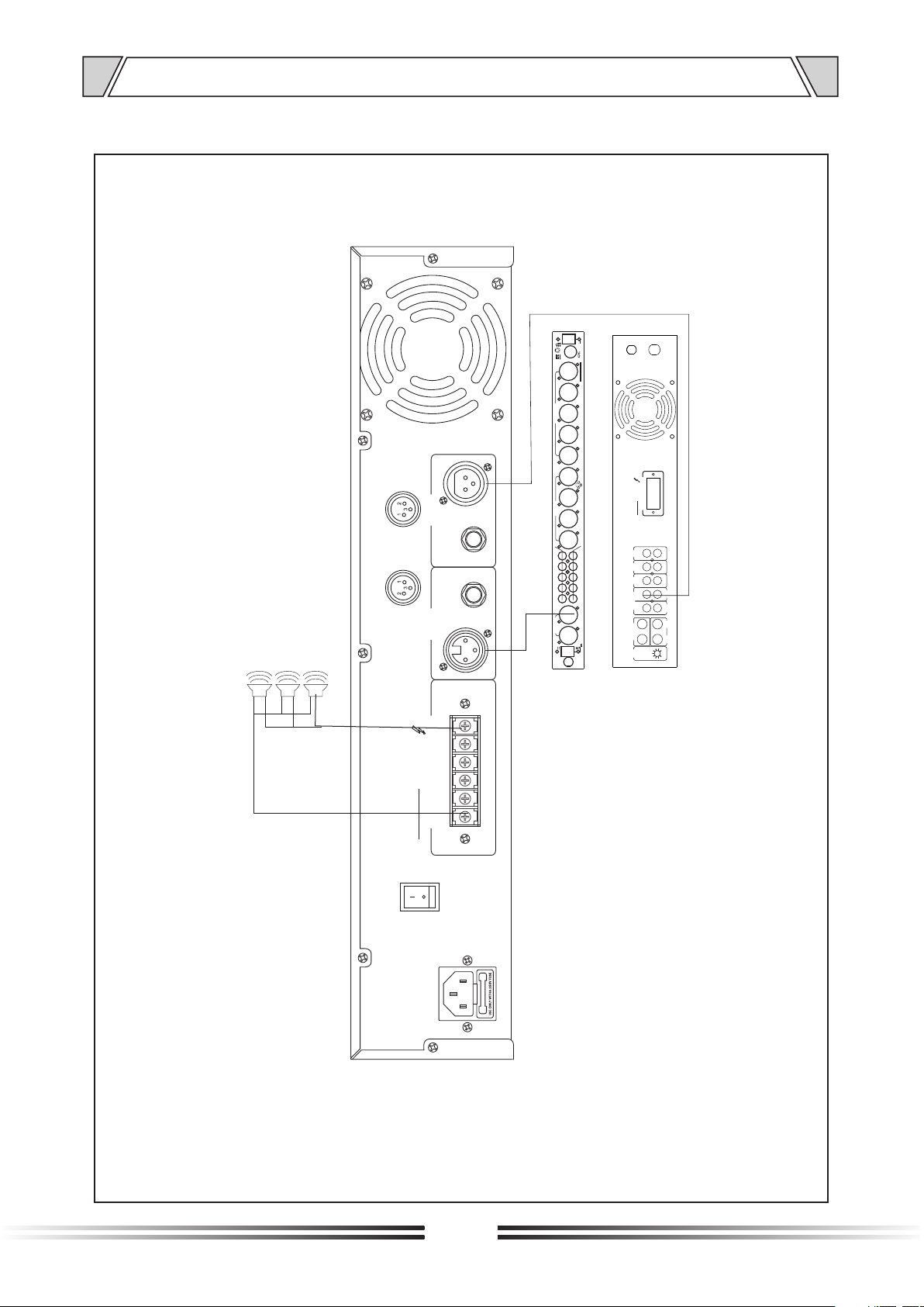
REAR PANEL CONN ECTIONS
3
2
1
6
4
1
CHIME
2
5
REMOTE
3
7
MIC INPUT
7
6
5
4
P.T.T 1 2
GND
CHIME
LED PWR
PRIORITY
3
SERIAL NO:
4
MODEL NO: IPA-SMP2
5
PRE AMPLIFIER
6
PUBLIC ADDR ESS S YST EM
789
3
2 1
MIC INPUTS MIC/LINE INPUTS
10
LEFT
RIGHT
1-G ND
XLR B AL
2-H OT+
3-C OLD-
INP UTS LIN K
INP UTS LIN K
12
3
LINE 7
LINE 10 LINE 9 LINE 8
REC
2--OUTPUTS--1
24V MAX 0.6A
DC POWER
MAX 9.9W
INSIDE AC/DC
FUSE 220VAC
220V/50Hz
OUTPUT
COM 4-16 ¦ 70V 100 V
OUT
AUX2
AUX1
MIC3
LINE INP UT
MIC2
MIC3
EMC INPUT
MIC2
MUTE
Speaker
70V 1 00V
4-16 ¦
OUT PUTS
COM
COM COM
LIF T
GND
13
Page 14
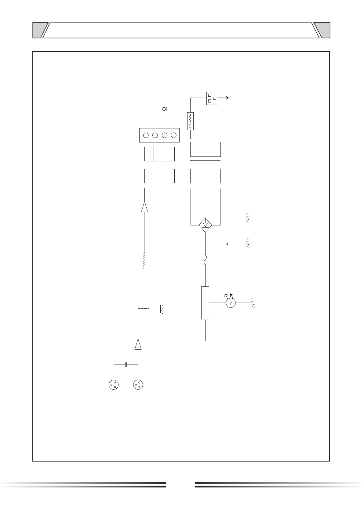
9. BLOCK DIAGRAM
230V
~ 50Hz
70V
100V
COM
4~16
TO
PA
PT
Z
POWER
EB
CH1 LINK
CH1 INPUTS
14
Page 15
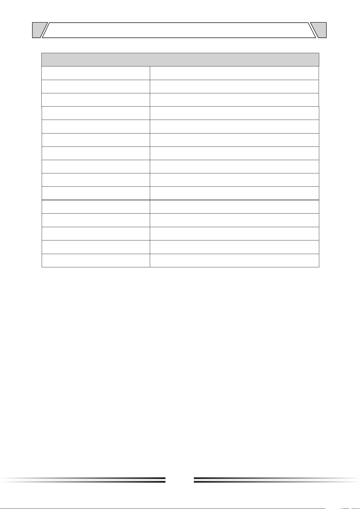
10. SPECIFICATIONS
POWER AMLIFIER
MODEL
RATED POWER OUTPUT
SPEAKER OUTPUTS
INPUT SENSITIVITY
FREQUENCY RESPONSE
S/N RATIO
T.H.D
CONTROLS
INDICATORS
PROTECTION
POWER REQUIREMENTS
POWER CONSUMPTION
DIMENSION(mm)
NET WEIGHT
IPA-1C240
240W
4~16¦,70V/100V
775mV/0dB
50Hz~18KHz
Better than 105dB
Less than 1% at 1KHz, 1/3 rated power
Power switch, volume control
Power, clipping , Signal , protect and high
AC fuse, short-circuit , clipping and high temperature
~230V 50Hz
440W
484X353X88
13.2Kg
GROSS WEIGHT
14.6Kg
15
Page 16
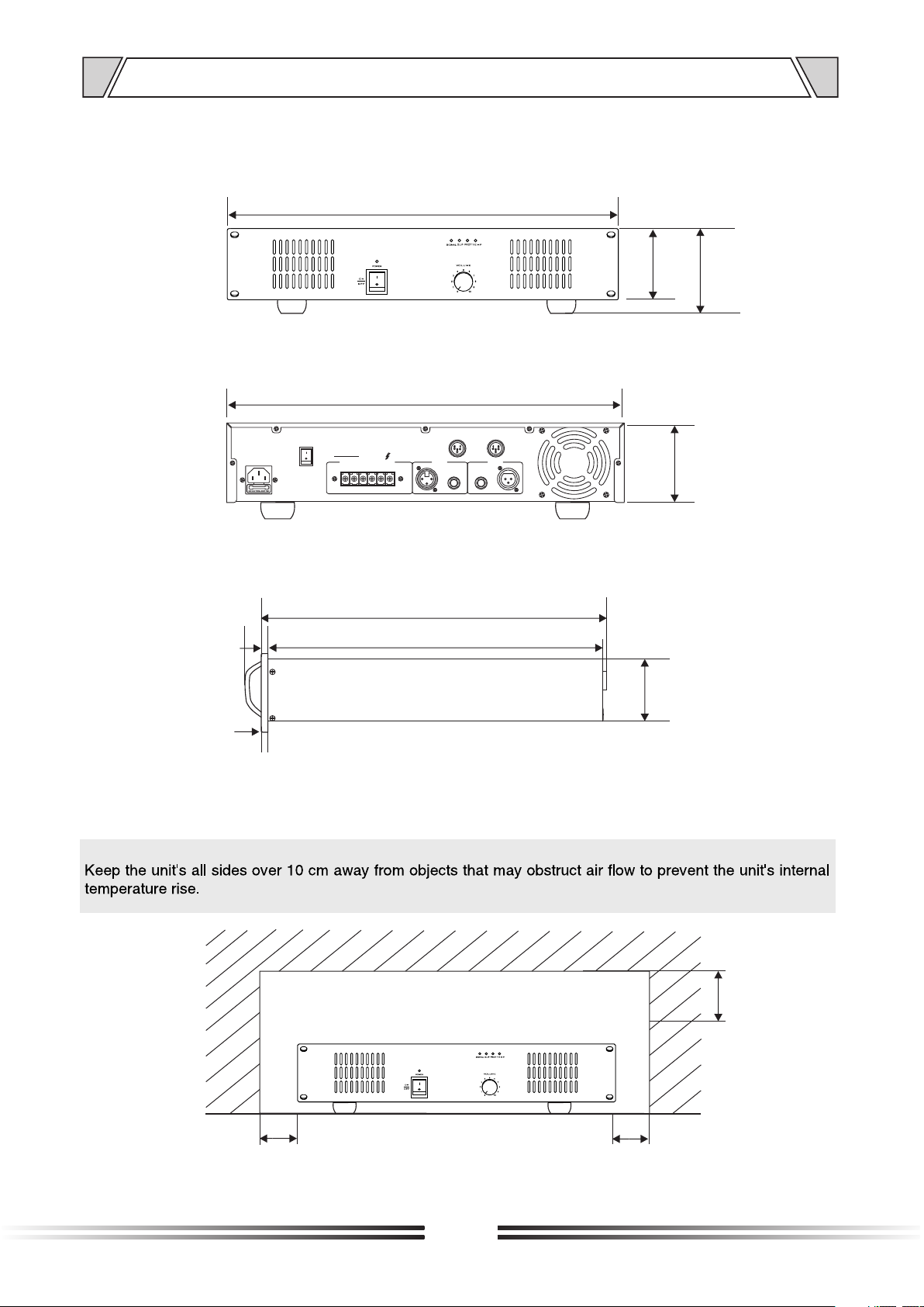
11. DIMENSIONAL DIAGRAM
UNIT :mm
484
94
88
436
INPUT S LINK
XLR BAL
1-GND
GND
OUTPU TS
4-16¦
70V 100 V
COM
COM COM
LIFT
2-HOT+
3-COLD -
INPUTS LINK
12
3
84
UNIT :mm
323
317
25
84
6
100
Over
100
16
Over
Over
100
Page 17

PUBLIC ADDRESS SYSTEM
PUBLIC ADDRESS SYSTEM
Version V0.1
 Loading...