

Page 1
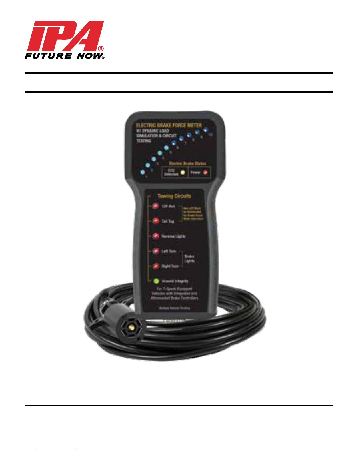
#9107A
ELECTRIC BRAKE FORCE METER WITH
DYNAMIC LOAD SIMULATION AND CIRCUIT TESTING
OPERATOR’S MANUAL
For 7-Spade Equipped Vehicles with
Integrated and Aftermarket Brake Controllers
Innovative Products of America® Incorporated
888-786-7899 • 234 Tinker Street, Woodstock, NY 12498 • www.ipatools.com
Page 2

LETTER FROM THE PRESIDENT OF IPA
®
My name is Peter Vinci and I am the president of IPA®. I would like to thank
you for your interest in IPA®’s product line and share my commitment
to you, our products and our policies. In today’s world, we have all
experienced the lack of service and consideration demonstrated by many
companies after you buy their products. They say whatever they can to
make the sale, and then it’s like pulling teeth to get any service response
out of them. I know this myself rst hand and because of this, I want to be
sure that your experience with IPA® meets your expectations and that IPA®
never disappoints you with our service or customer response.
To prove my commitment to you, if for any reason, you are not happy with
one of our products – or more importantly, with the response from our
customer service department, or any member of the IPA® team, I invite you
to contact me directly via my email, [email protected] or call me
at 888-786-7899. Your satisfaction is more important to me than the sale
itself. We will not be in business for long if we don’t make you completely
happy with our products and service. I want IPA® to be different and be
known for its quality and service.
With that said, please take a look at our product line. You will see
innovative rst time products that were created to help you do your job
faster and better than before.
I would also like to invite you to critique our products. If you can think of
a better way to make them or changes that will make them work better,
please contact me directly and I will be sure to look into it. If you have an
innovation and would like some feedback, give me a call.
From all of us at IPA®, we thank you for taking the time to review our
product line and wish you and your family the very best of everything.
Peter Vinci
President
®
IPA
www.ipatools.com
Toll Free: 888-786-7899
Phone: 845-679-4500
Fax: 845-679-4600
2
Page 3
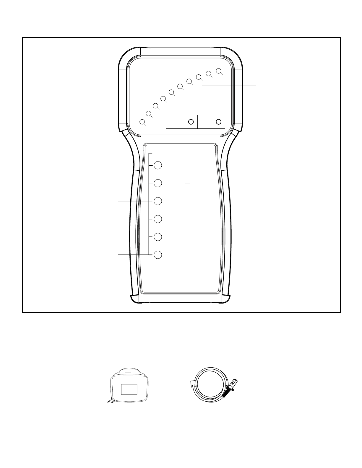
WHAT’S INCLUDED
Electric Brake
ELECTRIC BRAKE FORCE METER
W/ DYNAMIC LOAD
SIMULATION & CIRCUIT
TESTING
5
4
3
Electric Brake Status
2
1
ECU
Detected
Towing Circuits
8
7
6
Power
10
9
Brake Force
Meter
Status
Towing Circuits
Ground Integrity
INCLUDED PARTS AND ACCESSORIES
12V Aux
Tail Tag
Reverse Lights
Left Turn
Right Turn
Ground Integrity
For 7-Spade Equipped
Vehicles with Integrated and
Aftermarket Brake Controllers
Multiple Patents Pending
One LED Must
be Illuminated
for Brake Force
Meter Operation
Brake
Lights
#9107A-AS
Soft Case
#9107-3
Use the Provided Reference Numbers When
Ordering Products and Parts Above
25 ft. 7-Flat Pin Cable
#KCBL-9107-AS
Toll Free: 888-786-7899
3
Page 4

COMPATIBILITY
The #9107A Electric Brake Force Meter with Dynamic Load Simulation
and Circuit Testing is designed to work with most all year/make/model
vehicles equipped with 7-spade trailer connections. If you suspect the
Electric Brake Force Meter does not work with your application, please call
us at 845-679-4500.
INTRODUCTION
The#9107A Electric Brake Force Meteris a professional, high-quality tool
that allows you to test the electric brake controller output and all tow-lighting
functions without a trailer present.
PRECAUTIONARY EXPLANATION:
Before testing, it’s important to note that there are several different methods
utilized by OEMs for establishing connections to trailers and automatically
adjusting gain. In most cases, each OEM takes their own approach to the
design and function of Electric Trailer Brake Controllers. Additionally, the
OEM’s methods have evolved over the years. Never assume that any two
makes or different year ranges will act the same way. For example, some
controllers limit output gain unless the vehicle is moving. Others limit output
gain unless the vehicle’s sensors detect heavy braking under load while moving. Some others allow full output for a short period of time and then limit the
output until the vehicle is moving. The purpose of this tool is to allow you to
view the output of the vehicle in real time without a trailer present.
PRETEST SET-UP
(MUST FOLLOW EACH USE!)
NOTICE: Brake Force Meter w/ Dynamic Load Simulation and Circuit
Testing will not function unless Tail/Tag or 12V Aux Circuits have
constant power.If your vehicle does not supply 12V Aux at the trailer
connector, leave parking lights on while testing.
WARNING: SET-UP MUST BE COMPLETE BEFORE
ATTACHING CABLE.
WARNING: WHEN TESTING IN CAB, DO NOT PINCH CABLE IN
WINDOW OR DOOR.
4
Page 5

SET-UP
1. With meter disconnected from cable, plug 7-way connector to back of vehicle.
2. Bring other end of cable and tester into driver's compartment, leaving
tester disconnected.
3. Set Emergency Brake.
4. Turn Vehicle Engine ON and let idle.
5. KEEP FOOT OFF BRAKE. ONLY AFTER engine is running, plug the 9-pin
connector to the socket of the tester and lightly tighten the thumb screws.
6. Verify 12V circuit is powered or turn on Tail/Tag Circuit.
7. Wait for yellow ECU detection light to stop blinking.
8. For vehicles equipped with integrated controllers, look for the words
"Trailer Connected" on your instrument panel and the ECU Detection
light to remain steady within a few seconds of connecting the #9107A
to a vehicle with engine running.
9. Set-up is now complete.
ALTERNATIVE SET-UP PROCEDURE
In 2016 and 2017 models, some OEMs changed the way the brake controllers search for a trailer signal. To establish a “Trailer Connected” message
with these vehicles if the basic method described above does not work,
press and hold the brake pedal during #7 of the Set-up Procedure. May not
work on GM model years ranging from '07-'10.
TESTING
1. With the #9107A connected and engine running, increase the brake force
adjustment on your instrument panel to maximum output (usually #10).
2. Without applying pressure to the brake pedal, operate the manual brake
lever on your controller and take note of the number of LEDs that illuminate. It is recommended to maintain application for up to 20 seconds
and observe any changes.
3. Release the manual brake lever and apply moderate pressure to the
brake pedal. Observe the series of 10 LEDs at the top of your tester as
they sequentially illuminate. This indicates the extent of 12V power available at the connector to actuate trailer brakes.
4. While increasing brake pressure, you should see more of the 10 LED
5
Page 6

SET-UP
1. With meter disconnected from cable, plug 7-way connector to back of vehicle.
2. Bring other end of cable and tester into driver's compartment, leaving
tester disconnected.
3. Set Emergency Brake.
4. Turn Vehicle Engine ON and let idle.
5. KEEP FOOT OFF BRAKE. ONLY AFTER engine is running, plug the 9-pin
connector to the socket of the tester and lightly tighten the thumb screws.
6. Verify 12V circuit is powered or turn on Tail/Tag Circuit.
7. Wait for yellow ECU detection light to stop blinking.
8. For vehicles equipped with integrated controllers, look for the words
"Trailer Connected" on your instrument panel and the ECU Detection
light to remain steady within a few seconds of connecting the #9107A
to a vehicle with engine running.
9. Set-up is now complete.
Circuit Type of Fault Diagnostic Procedure
Check for faulty connection, fuse,
wiring fault or controller gain too low.
Check for faulty connection or
controller gain too low.
Check for faulty connection or
controller gain too low.
Check for faulty connection, fuse
or defective asher.
Check for faulty connections for
wiring fault.
Check for wiring fault, turn signal
operation or fuse if turn signals are
also dead.
Electric
Brake
Tur n
Signals
Brake
Lights
No indication when energized
Low current output or intermittent
No power indication when
energized
One or both stay on with no blink
Intermittent or erratic
illumination
No power indication when
energized
Intermittent or erratic
illumination
No power indication when
Tail/Tag
Lights
6
energized
Intermittent or erratic
illumination
Check for wiring, fuse or
connection faults.
Page 7

Reverse
Lights
(RED)
Power
Trailer Not
Detected
CONTINUED CHART
No power indication when
energized
Intermittent or erratic illumination
No power indication when
energized
Intermittent or erratic output
Vehicle does not recognize the
Brake Force Meter as a trailer
Check for wiring, fuse or
connection faults.
Check for wiring, fuse or
connection faults.
Check Set-up Procedure.
For 2016 and 2017 Ford models
- follow Alternative Set-up
Procedure (Below).
If you suspect your vehicle is not
compatible with this tool, contact
®
IPA
or 845-679-4500 for available
updates.
(Yellow
ECU
Detected)
(RED)
Power
ECU and
Power
Light
STATUS LIGHTS
Blinking Determining if ECU is present.
Steady
Not illuminated
Steady
Not illuminated No power or continuity detected
Intermittent blink
Blinking
ECU detected, dynamic load is
active.
No ECU detected. Static load is
available.
E. Brake Circuit has power and
continuity.
Indicates search signal from vehicle. This is typical and expected
from vehicles with an established
ECU connection.
Fault in wiring—check connections
and trouble codes.
(Blue)
Gain 1-10
Illuminated
Indicates gain from truck. 1.0-1.5V
increments.
7
Page 8

LIMITED ONE-YEAR WARRANTY
9107A-Manual-VA-01-04
#9107A
Electric Brake Force Meter with Dynamic Load
Simulation and Circuit Testing
Innovative Products of America® Incorporated has established a Limited One-Year
Warranty Policy for the Electric Brake Force Meter w/ Dynamic Load Simulation and
Circuit Testing, not including any wearable parts, i.e. batteries (30 day warranty),
battery clips, etc.
One-Year Limited Warranty/Return or Replace Policy: The product is covered for one
year from the date of original user purchase under the stipulations of the Standard
Warranty.
The product is warranted to be free from defects in workmanship or material. If there
is a problem due to workmanship or material defect, Innovative Products of America
Incorporated will repair or replace the product within 24 working hours after it is
received by the IPA® Repair Service Center. In the event it is determined that the
product has been tampered with, or altered in any way, the warranty is void and all
claims against the product will not be honored. The Warranty Repair/Return
procedures require that the proof of purchase must be established (either by warranty
card from the seller or by point of purchase receipt/invoice) and the manufacturer
makes every attempt to return ship the product within three business days from the
receipt of the returned product, freight prepaid.
®
If it has been determined that the tool has been damaged due to misuse, Innovative
®
Products of America
Incorporated will repair the tool at a cost we deem reasonable
and these charges will be the responsibility of the user. We truly want you to be happy
with our products, so if you have any questions, call us toll free at 888-786-7899.
(OEM) ORIGINAL EQUIPMENT MANUFACTURER USA
Innovative Products of America® Incorporated
234 Tinker Street, Woodstock, NY 12498
888-786-7899 • 845-679-4500 • www.ipatools.com
© 2018 Innovative Products of America® Incorporated. All rights reserved. This material may not be
reproduced, displayed, modied or distributed without the express prior written permission of the
copyright holder. For permission, contact [email protected].
 Loading...