

Page 1
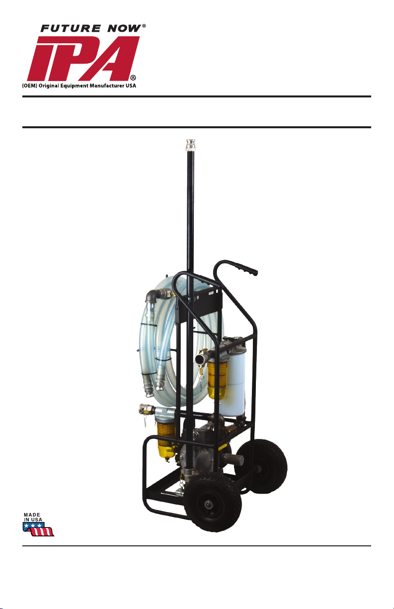
FUEL TANK SWEEPER
OPERATOR’S MANUAL
®
#9040PN
© 2012 Innovative Products of America®, Incorporated. All
rights reserved. This material may not be reproduced, dis-
played, modied or distributed without the express prior
written permission of the copyright holder. For permission,
contact [email protected].
Innovative Products of America® Incorporated
888-786-7899 | www.ipatools.com
234 Tinker Street, Woodstock, NY 12498
Page 2

LETTER FROM THE PRESIDENT OF IPA
My name is Peter Vinci and I am the president of IPA®. I would like to rst thank you for
your interest in IPA®’s product line and share my commitment to you, our products and
our policies. In today’s world, we have all experienced the lack of service and consideration demonstrated by many companies after you buy their products. They say whatever they can to make the sale, and then it’s like pulling teeth to get any service response
out of them. I know this myself rst-hand and because of this, I want to be sure that your
experience with IPA® meets your expectations and that IPA® never disappoints you with
our service or customer response.
To prove my commitment to you, if for any reason you are not happy with one of our
products or more importantly, with the response from our customer service or any mem-
ber of the IPA® team for any reason, I invite you to contact me directly via my email,
[email protected] or call me at 888-786-7899. Your satisfaction is more important to
me than the sale itself. We will not be in business for long if we don’t make you completely happy with our products and service. I want IPA® to be different and to be known
for its quality and service.
With that said, please take a look at our product line. You will see innovative rst time
products that were created to help you do your job faster and better than before. I would
also like to invite you to critique our products. If you can think of a better way to make
them or changes that will make them better, then again, please contact me directly and I
will be sure to look into it. If you have an innovation and would like some feedback, give
me a call.
From all of us at IPA®, we thank you for taking the time to review our product line and
wish you and your family the very best of everything.
Peter Vinci
President
®
IPA
www.ipatools.com
Toll Free: 888-786-7899
Phone: 845-679-4500
Fax: 845-679-4600
2
Page 3
IMPORTANT SAFETY INSTRUCTIONS
IT IS IMPORTANT TO READ, UNDERSTAND AND FOLLOW ALL SAFETY MESSAGES & INSTRUCTIONS PRINTED IN THIS MANUAL AND ON THE EQUIPMENT
BEFORE OPERATING. IF SAFETY INFORMATION IS NOT HEEDED, RESULTS IN
DEATH OR SERIOUS INJURY TO THE OPERATOR OR BYSTANDERS MAY OCCUR.
DANGER indicates a hazardous situation, if not avoided, will result in death or serious
injury. The possible hazards are shown in the adjoining symbols or explained in the text.
WARNING indicates a hazardous situation, if not avoided, could result in death or serious injury. The possible hazards are shown in the adjoining symbols or explained in the
text.
CAUTION indicates a hazardous situation, if not avoided, may result in minor or major
injury. The possible hazards are shown in the adjoining symbols or explained in the text.
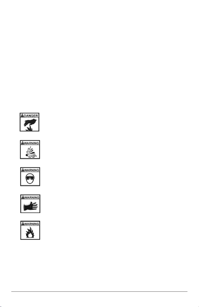
POTENTIAL BURN HAZARD Sparks from electrical shorts can ignite
ammable liquids such as fuel or oil. Heat from electrical overloads
can cause re hazards.
POTENTIAL EXPLOSIVE AIR HAZARD Pneumatic pressures used
with this equipment can cause explosive failures on damaged equipment.
POTENTIAL EYE HAZARD Wear OSHA approved safety glasses.
Battery acid and high air pressures create hazardous situations for eyes.
POTENTIAL CHEMICAL BURN HAZARD Wear protective gloves.
Battery acid is corrosive and can cause skin damage.
POTENTIAL FIRE HAZARD Use caution with ammable liquids such
as fuel and oil. Electrical shorts can ignite ammable liquids and wiring.
Warning: For use with diesel fuel and hydraulic oils only. Do not use with gasoline.
Do not use to transfer any hard contaminants such as rocks, leaves, etc. This can
damage the pump and void the warranty.
Warning: Do not operate with caps installed or bodily injury can result.
3
Page 4
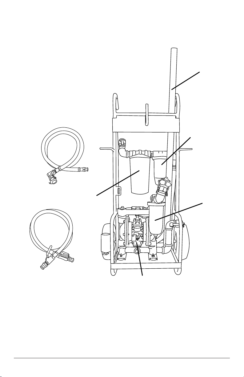
9040PN FUEL TANK SWEEPER® PARTS
PVC/FIBERGLASS
SUCTION STICK
WATER
BLOCKING
FILTER
CLEAR 1” HOSE
P/N FIL-10WB
90 DEGREE
SWIVEL
QUICK RELEASE
FEMALE COUPLER
QUICK RELEASE
MALE COUPLER
EMPTY FILTER
HOUSING: USED
CANISTER
FOR SITE GLASS
FILTER
(Can install
optional wire
mesh filter)
CLEAR 1” HOSE
BALL VALVE
QUICK RELEASE
MALE COUPLER
30 MICRON
P/N FIL-30PT
DIAPHRAGM PUMP
30 GPM
MUST READ BEFORE USE
This diaphragm pump is meant for use with liquids only. DO NOT suck
up leaves, gravel and other solids. Doing so will void the warranty.
Manufacturer suggests the use of a screen lter on the intake side.
(Reference part # 9040-TFIL)
4
Page 5

SET UP INSTRUCTIONS:
STEP 1
It is recommended that you visit the site 48 hours before tank sweeping to prepare the
tank and assess the site condition. Using the optional IPA9041 sampling tool, insert the
sampler all the way down to the bottom of the tank to be cleaned. Draw the piston shaft
up enough to get a good sample of the fuel (aprox.12”). Remove the sampler and note
the amount of water and crude at the bottom of the
tank. It is recommend that you transfer the sample
into a glass jar and allow the various
contaminants to settle and separate for
24 hours. This will give you an idea of the fuel
condition inside the tank and the amount and type
of the contaminated fuel.
STEP 2
Add an algae bio-cleaner or equivalent to the tank in appropriate amounts. Using the
sampler, stir the tank briskly to mix the algae cleaner into the oil. After 48 hours, the
algae should be killed off and the tank is now ready for sweeping. If convenient and
safe, you may use a small jack to elevate the tank a few degrees on one side to allow
the majority of contaminates to collect on one end of the tank. This is the end you will
choose to sweep.
TANK SWEEPING SET-UP:
1. Set up your Tank Sweeper™ near the tank to be cleaned allowing enough room
for
the inlet hose to reach the tank.
2. Install the outlet hose to a 55 gallon drum similar making sure that the vent cap is
loose. (Note: Use a clean, and leak free 55 gallon drum).
3. Connect the suction stick to the inlet hose via couplings being sure to use the
locking pins so the locking levers do to vibrate loose.
4. Insert the suction stick adapter all the way down to the bottom of the oil tank to be cleaned.
5. Be certain to turn the main ball valve to Sweeper™ direction.
6. Attach air supply line to the inlet air on the pump assembly. Do not turn on the air
ball valve yet.
7. Set the air pressure to 50 PSI. Air Operating Range is from 50 PSI to 100 PSI. A
setting of 50 PSI is recommended to give the operator more control of the sweeping
operation. Do not turn on the air ball valve yet.
NOTE: When ready to sweep the tank, be sure to check all connections for leaks
and be prepared to shut down the sweeper in the event of a leak. Have your Emergency Spill Kit available and in reach. It is best to have this operation performed
by two people--one operating the air supply and the other person doing the actual
sweeping of the tank.
5
Page 6

TANK SWEEPING:
1. Once all safety precautions have been complied with and you are certain of good
and proper connections with the outlet hose rmly in the holding drum turn the AIR
INLET ball valve to the ON position. This begins to actuate the pump assembly and
suction through the Fiber Staff adapter. IN THE EVENT OF AN EMERGENCY
FIRST CLOSE AIR BALL VALVE TO STOP THE PUMP.
2. Keep the adapter at the bottom of the tank and slowly sweep back and forth collecting
all contaminants from the bottom of the tank only.
NOTE: The pump can move up to 30 gallons per minute (GPM) at 100 PSI and ll
up a 55 gallon drum in a very little time. Watch carefully and be sure not to place
more than 50 gallons into the drum. This allows room for fuel expansion. Depending upon the amount of contaminates in the oil tank, you may require two or more
55 gallon drums to complete the service.
3. The Tank Sweeper® will remove the bottom contents of the tank where the majority
of fuel contaminants exist, i.e., water, crude, algae and rust. If a badly contaminated
tank is expected, it would be best to run the cleaning through the lower lter housing
without the screen. The Sweeper® function can incorporate an optional wire mesh
lter which can capture the majority of the rust and large contaminates. However, the
screen openings can still be clogged up quickly causing an implosion of the screen
and a reduction of the ow.
The Tank Sweeper® operator should move the Fiber Staff back and forth across the
bottom of the tank moving the stick. You will see the oil turn black, then when that
spot is clean, it will turn red. This is an indication to move the staff to another spot
on the bottom of the tank. Repeat this sweeping function until only clean fuel is
removed. It may be necessary to use two 55 gallon drums depending upon the
amount of contaminates found.
NOTE: Be mindful of the 55 gallon drum level and be sure not to over-ll. Have
your Emergency Spill Kit ready and available in case of a spill. Leave sufcient
air space for expansion.
After the sweeping is complete, remember to lower the tank to a level position by
removing the jack.
Remove the outlet hose from the 55 gallon drum and install all vent or port caps
and seal drum completely for transport.
FILTERING AND BLENDING THE FUEL:
A great feature for the Sweeper® is the ability to return the contaminated fuel clean and
ltered to the same or new oil tank. To do this, allow the 55 gallon drum with the fuel that
came from the sweeping to sit and settle for 24 hours.
1. Turn the main Ball Valve to the Filter Selection and you can complete the fuel restoration.
Observe all instruction on page 3, 4 and 5 (up to Tank Sweeping™ section.)
2. Install the outlet hose in the tank you want to transfer the cleaned fuel into.
3. Insert the Fiber Staff on the Filter intake side into the top of the 55 gallon drum
allowing it to just contact the fuel at the top of the drum.
6
Page 7

NOTE: When ready to sweep the tank, be sure to check all connections for leaks
and be prepared to shut down the sweeper in the event of a leak. Have your Emergency Spill Kit available and in reach. It is best to have this operation performed
by two people--one operating the air supply and the other person doing the actual
sweeping of the tank.
4. When in the ltering mode and turning the air valve to the ON position, slowly lower
the ber staff into the 55 Gallon drum following the fuel level watching the clear
hose for signs of black contamination. The contaminates will be settled in the last
few inches of the drum so when you get close to the bottom and as soon as you
see the color of the fuel change to dark, lift up the ber staff and stop the transfer
operation. Dispose of the bottom of the tank with the contaminated fuel properly.
IF YOU WISH TO BLEND FUEL ADDITIVES OR FILTER THE OIL IN THE TANK:
1. While observing all safety precautions, turn the Sweeper® to the Filter selection via
Main Ball Valve.
2. Insert Fiber staff into one hole at the top of the tank and insert the outlet hose into
another hole at the top of the tank.
NOTE: When ready to sweep the tank, be sure to check all connections for leaks
and be prepared to shut down the sweeper in the event of a leak. Have your Emergency Spill Kit available and in reach. It is best to have this operation performed
by two people -- one operating the air supply and the other person doing the
actual sweeping of the tank.
3. Turn the air valve on and allow the fuel to circulate through the lters and back into
the tank. At this point you can turn the pressure up to maximum or 100 PSI to
achieve a 37GMP rate. With this rate, you can move 275 gallons of fuel oil through
the sweeper in several minutes. If there is a noticeable decrease in the fuel ow
rate, the problem may be clogged lters. If this is the case, replace lter cartridges
as necessary.
OPTIONAL ACCESSORIES:
8 FT. EXTENSION HOSE #9040-8EXT
1. To connect the 8ft. Extension Hose between the Sweeper® and
the hose that you want to extend, take the male quick disconnect
of the 8ft. extension hose and put it into the desired female port
of the Sweeper.
2. Take the female end of the 8 ft. extension hose and attach it to
the male end of the hose you are extending.
3. To couple the male and female quick disconnects together, put
the male quick disconnect into the female quick disconnect.
4. Pull the levers on the side of the female end all the way down towards itself tight
against the side. Be sure to insert the cotter pins through the hole to lock the levers
in place.
NOTE: During the pump operation, excessive vibration has a tendency to vibrate
loose the coupling locking handles. Be certain to use the locking cotter pins.
7
Page 8
5. To maintain the clear appearance of the hose after use, it is good practice to gravity
drain all uid from the hose. Then using warm soapy water, ush until clean and air
drain and dry afterwards.
NOTE: Depending upon what contaminates are present when using the hose and
how well it is cleaned afterwards determines how long the hose remains clear.
The hose is warranted to be free from manufacturer’s defects for one year.
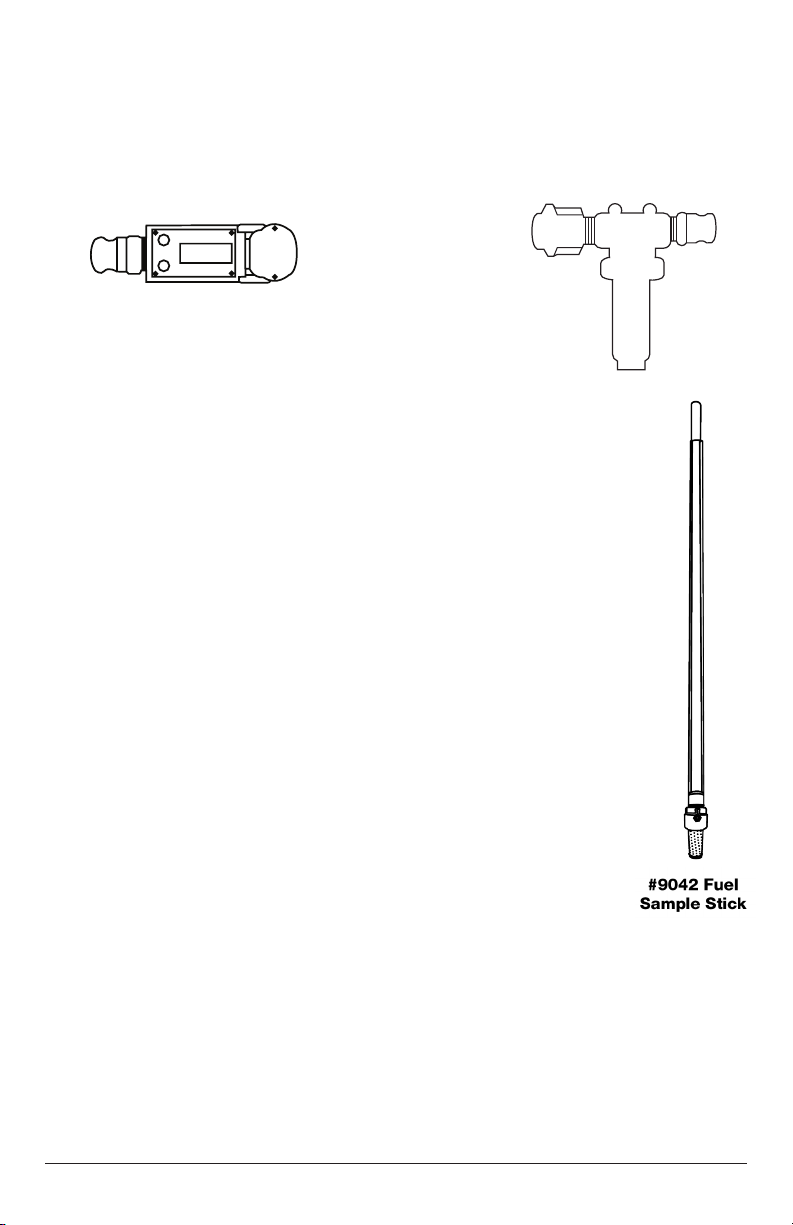
Digital Flow Meter
9040-FLOM
T-Filter for
large particles
9040-TFIL
SAMPLE STICK #9042
The Sample stick is designed to remove a small sample of fuel oil from
the bottom of a fuel tank so the operator can see what contaminates exist.
TO OPERATE:
1. Insert the Sample Stick through one of the cap openings at the top
of the tank all the way until it contacts the bottom of the tank.
2. Slowly withdraw the piston via the handle until the desired amount
of fuel is drawn into the Sample Stick.
3. Remove the sample stick from the tank keeping an oil absorbent
towel ready. Allow the Sample Stick to drip drain into the towel.
4. Have a suitable container made of glass or material that will not be
affected by the fuel oil ready for the sample fuel oil.
5. Slowly withdraw the piston until it is removed completely from the
sample tube. Place the piston on a towel to drip drain.
6. Pour the remaining contents of the sample tube into the sample jar.
7. Once the sample is in the jar, let it sit for 24 hours to separate the
contents. The water will settle to the very bottom with rust, and
then algae, then the crude. The clear oil will be on top. This
should be a real time view of what is happening at the bottom of the
oil tank.
8. Once the sample has been taken, you must replace the piston in the sample stick
tube. Because of the one way valve at the bottom of the foot valve, there will be a
pressure block as you attempt to replace the piston. You need to break the suction
seal by unscrewing the foot valve two turns counter clockwise. This allows the air
to escape and the piston to be replaced. Once the piston reaches the bottom of the
tube, you must retighten the foot valve. Be certain not to over- tighten the O-ring.
8
Page 9

A snug torque of the foot valve halves is all that is needed. Cleaning of the Sample Stick
after use is necessary to maintain its clear appearance. When ready, allow the Sample
Stick to gravity drain the oil. Once the stick has been drained, a solution of warm soapy
water should be used to ush the stick a few times until clean.
NOTE: The tube of the sample stick is made of a clear acrylic material. The
Sample stick should not be used for gasoline, ONLY OIL!
OPTIONAL FILTERS
25 MICRON LARGE HYDRAULIC FILTER #FIL00003B
16 MICRON LARGE HYDRAULIC FILTER #FIL00003C
SMALL WIRE MESH FILTER #FIL-300M
NOTE: One extra lter each of the large 30 MICRON FILTER FIL-30PT and SMALL
10 MICRON WATER BLOCKER FIL-10WB are included. Addtional quantities
avaiable from IPA®.
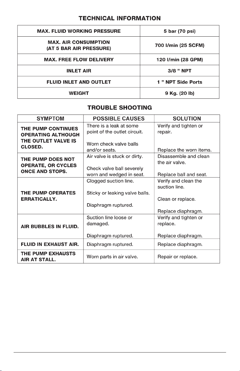
AIR-OPERATED DIAPHRAGM PUMP DESCRIPTION
1:1 ratio air-operated diaphragm pump with aluminum body and Buna N diaphragms.
Recommended for transferring oil or evacuating waste oil.
9
Page 10
10
Page 11

NOTES
11
Page 12

Limited One Year Warranty
009040PN-MANUAL-IPA
FUEL TANK SWEEPER
®
#9040PN
Innovative Products of America® Incorporated has established a Limited One Year Warranty
Policy for the Fleet Tank Sweeper®.
One Year Limited Warranty/Return or Replace Policy: The product is covered for one year
from the date of original user purchase under the stipulations of the Standard Warranty.
The product is warranted to be free from defects in workmanship or material. If there is a prob-
lem due to workmanship or material defect, Innovative Products of America® Incorporated will
repair or replace the product within 24 working hours after it is received by the IPA® Repair
Service Center. In the event it is determined that the product has been tampered with, or
altered in any way, the warranty is void and all claims against the product will not be honored.
The Warranty Repair/Return procedures require that the proof of purchase must be established (either by warranty card from the seller or by point of purchase receipt/invoice) and the
manufacturer makes every attempt to return ship the product within three business days from
the receipt of the returned product, freight prepaid.
If it has been determined that the tool has been damaged due to misuse, Innovative Products
of America® Incorporated will repair the tool at a cost we deem reasonable and these charges
will be the responsibility of the user. We truly want you to be happy with our products, so if you
have any questions, call us toll-free at 888-786-7899.
Innovative Products of America® Incorporated
234 Tinker Street, Woodstock, NY 12498
888-786-7899 / 845-679-4500 | www.ipatools.com
© 2012 Innovative Products of America®, Incorporated. All rights reserved. This material may not be reproduced, displayed, modied or
distributed without the express prior written permission of the copyright holder. For permission, contact [email protected].
 Loading...