

Page 1
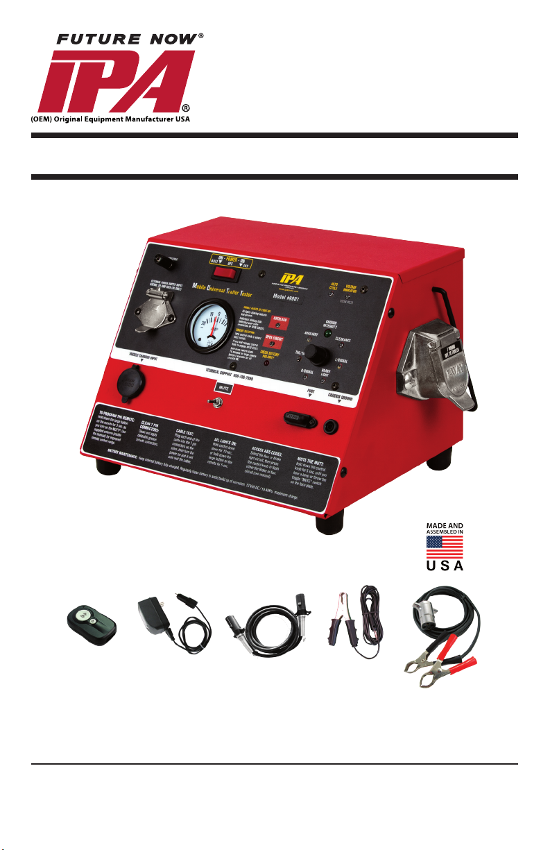
Mobile Universal Trailer Tester
#9007A SMART MUTT
OPERATOR’S MANUAL
®
Uses Internal 12 Volt Motorcycle Battery.
Tests Trailers Using 7 Round Pin Type Connections.
© 2012 Innovative Products of America®, Incorporated. All
rights reserved. This material may not be reproduced, dis-
played, modied or distributed without the express prior
written permission of the copyright holder. For permission,
contact [email protected].
Innovative Products of America® Incorporated
845-679-4500 | www.ipatools.com
234 Tinker Street, Woodstock, NY 12498
Page 2

LETTER FROM THE PRESIDENT OF IPA
My name is Peter Vinci and I am the president of IPA®. I would like to rst thank you
for your interest in IPA®’s product line and share my commitment to you, our products
and our policies. In today’s world, we have all experienced the lack of service and
consideration demonstrated by many companies after you buy their products. They
say whatever they can to make the sale, and then it’s like pulling teeth to get any
service response out of them. I know this myself rst-hand and because of this, I want
to be sure that your experience with IPA® meets your expectations and that IPA®
never disappoints you with our service or customer response.
To prove my commitment to you, if for any reason you are not happy with one of our
products or more importantly, with the response from our customer service or any
member of the IPA® team for any reason, I invite you to contact me directly via my
email, [email protected] or call me at 888-786-7899. Your satisfaction is more
important to me than the sale itself. We will not be in business for long if we don’t
make you completely happy with our products and service. I want IPA® to be different
and to be known for its quality and service.
With that said, please take a look at our product line. You will see innovative rst time
products that were created to help you do your job faster and better than before. I
would also like to invite you to critique our products. If you can think of a better way
to make them or changes that will make them better, then again, please contact me
directly and I will be sure to look into it. If you have an innovation and would like some
feedback, give me a call.
From all of us at IPA®, we thank you for taking the time to review our product line and
wish you and your family the very best of everything.
Peter Vinci
President
IPA®
www.ipatools.com
Toll Free: 888-786-7899
Phone: 845-679-4500
Fax: 845-679-4600
2
Page 3
B
G
A
H
C
D
E
F
K
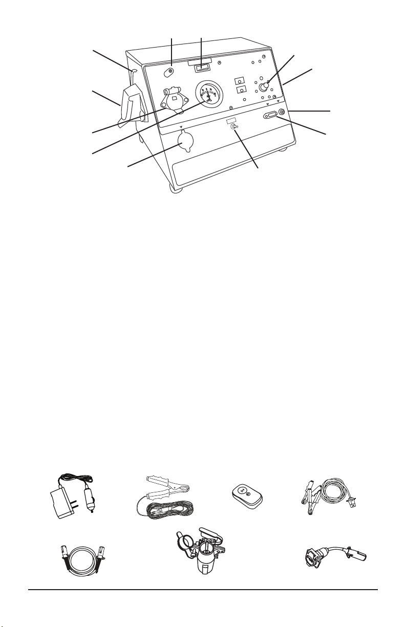
A CARRYING HANDLE
B ANTENNA POST
C 7 ROUND SOCKET (CABLE TEST SIDE)
D EXTERNAL (OPTIONAL) POWER INPUT
E 30 AMP AMMETER GAUGE
F TRICKLE CHARGE INPUT
G POWER SWITCH
H CONTROL KNOB
I CHASSIS GROUND PLUG
J FUSE, 30 AMP ATO/ATC
K MUTE SWITCH
L 7 ROUND SOCKET (TRAILER TEST SIDE)
M REMOTE CONTROL FOB (#7900K-34)
N 10 FT. CHASSIS GROUND CABLE (#7900K-2BCHAS)
O 500 mA/12V TRICKLE CHARGER (#CHR00001)
P EXTERNAL POWER CABLE (#7900K-93)
Q 7 ROUND CABLE (#7900K-1)
OPTIONAL ADAPTERS:
R 7 FLAT TO 6 ROUND & 4/5 FLAT ADAPTER (#8000)
S 7 ROUND TO 7 FLAT ADAPTER (#7900A-5)
L
I
J
O
Q R
N
M
3
P
S
Page 4
IMPORTANT SAFETY INSTRUCTIONS
IT IS IMPORTANT TO READ, UNDERSTAND AND FOLLOW ALL SAFETY MESSAGES and INSTRUCTIONS PRINTED IN THIS MANUAL AND ON THE EQUIPMENT BEFORE OPERATING. IF SAFETY INFORMATION IS NOT HEEDED, SERIOUS INJURY OR DEATH TO THE OPERATOR OR BYSTANDERS MAY OCCUR.
THE FOLLOWING SAFETY ALERT SYMBOLS ARE USED IN THIS MANUAL.
DANGER: indicates a hazardous situation, if not avoided, will result in death orserious injury. The possible hazards are shown in the adjoining symbols or explained in
the text.
WARNING: indicates a hazardous situation, if not avoided, could result in death or
serious injury. The possible hazards are shown in the adjoining symbols or explained
in the text.
CAUTION: indicates a hazardous situation, if not avoided, may result in minor or
major injury. The possible hazards are shown in the adjoining symbols or explained in
the text.
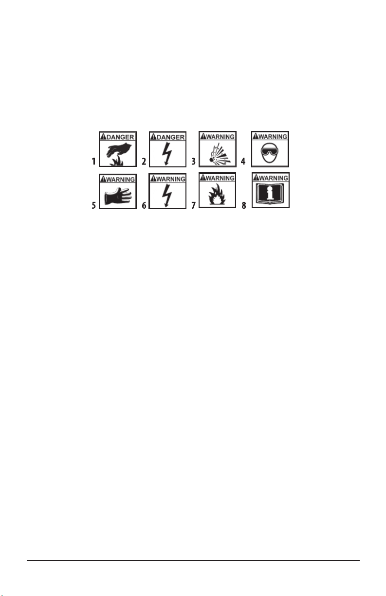
SYMBOL 1: Potential burn hazard. Sparks from electrical shorts can ignite
ammable liquids such as fuel or oil. Heat from electrical overloads can cause re
hazards.
SYMBOL 2: Potential electrical hazard. Batteries have enough electrical energy
potential to ignite ammable liquids such as fuel or oil. Wire overloads can cause
electrical failures. Shock hazard exists.
SYMBOL 3: Potential explosive air hazard. Pneumatic pressures used with this
equipment can cause explosive failures on damaged equipment.
SYMBOL 4: Potential eye hazard. Wear OSHA approved safety glasses. Battery acid
and high air pressures create hazardous situations for eyes.
SYMBOL 5: Potential chemical burn hazard. Wear protective gloves. Battery acid is
corrosive and can cause skin damage.
SYMBOL 6: Potential electrical hazard. Electrical energy can cause heat and burn
hazards.
SYMBOL 7: Potential re hazard. Use caution with ammable liquids such as fuel
and oil. Electrical shorts can ignite ammable liquids and wiring.
SYMBOL 8: Important information is stated.
4
Page 5
BATTERY GASES, TESTER PREPARATION
AND TESTER/CHARGER LOCATION
RISK OF EXPLOSION
• Gases produced by a battery are highly explosive.
• Wear safety goggles and protective clothing, both users and bystanders.
• Use in an area having at least four air changes per hour.
• Read, understand and follow all instructions for charger, battery, vehicle and
any equipment used near battery and charger.
• Do not smoke, strike a match, place metal tools on battery or cause a spark
in the vicinity of the battery. When removing battery cables, remove the
ground cable rst.
• Clean terminals before charging battery. During cleaning, keep corrosive
particles from eyes, nose and mouth. Use baking soda and water to neutralize
acid and help eliminate airborne corrosion.
• Never allow clamps on charger cables to touch each other.
• Do not expose tester or charger to rain, snow, or wet conditions.
• Do not allow battery gases or acid to contact MUTT® cabinet.
• Do not place charger directly above or below battery.
• Fill battery to level specied by battery manufacturer using distilled water.
• Do not remove cell caps while charging per manufacturer’s instructions.
• Make sure tester cable clamps make tight connections.
•Battery explosion can cause injury.
ACID BURNS
• Battery acid is highly corrosive sulfuric acid.
• Wear safety goggles, both user and bystanders.
• Wear safety gloves.
• Make sure someone can hear you or is close enough to provide aid when working
near battery.
• Have plenty of fresh water and soap nearby. If battery acid contacts skin,
clothing or eyes, ush the exposed area with soap and water for 10 minutes.
Seek medical help.
• Do not touch eyes while working near battery.
• Battery acid can burn eyes and skin.
5
Page 6
GENERAL CHARGER USE
DC POWER ONLY
Do not plug directly into
AC wall outlet.
RISK OF ELECTRIC SHOCK AND FIRE
• Before connecting power cord to charger, make sure controls are set to off.
• DC power only.
• Do not plug directly into AC wall outlet.
• Do not remove or bypass the grounding pin.
• Do not operate charger with damaged cord or plug. Replace cord or plug
immediately.
• (OPTIONAL CHARGER)
• Position power cord and charger cables away from the hood, doors or hot and/
or moving engine parts where they could be damaged.
• Unplug power cord using plug rather than cord when disconnecting charger
from outlet.
• Charger power cord uses equipment-grounding conductor and a
grounding plug. Plug only into a 3 prong 120 VAC outlet that is correctly
installed and grounded in accordance with all ordinances and local codes.
• Unplug power cord from outlet before cleaning or maintaining tester and
charger. Turning off controls does not reduce this risk.
• Do not operate charger after a sharp impact, dropping or any other damage.
Do not disassemble charger.
• Use only recommended attachments.
• Do not charge a frozen battery. Do not overcharge a battery.
• Use charger only for lead-acid automotive batteries. Do not use charger for
charging dry cell batteries.
• Electric shock or re can cause injury.
RISK OF ENTANGLEMENT
• Keep yourself, clothing and battery charger leads clear of moving parts such
as fan blades, pulleys, hood, and doors.
• Moving parts can cause injury.
RISK OF BURNS
• Batteries can produce short circuit current high enough to weld jewelry such
as rings, bracelets and watches. You must remove them before working
near batteries.
• Short circuits can cause injury.
6
Page 7

QUICK REFERENCE GUIDE
OPERATION AND TESTING
ELECTRICAL TESTING
1. CABLE TESTING: It is always recommended to use the cable tester to verify that
the MUTT®’s 7 round pin cable used is in proper working order
before trailer testing. To perform Cable Test insert both ends of the 7 pin
cable one in each receptacle on the MUTT’s side. Once the cable is installed, turn
the MUTT® ON to verify the continuity between both ends of the cable. Look for the
solid green light verifying Ground Integrity and note if there are any green circuit
LEDs blinking. Note that each circuit is tested upon start up as well as ground fault
check. Solid LEDs mean Good connection, Blinking LEDs indicate an open circuit
or poor continuity. The cable tester can also be used to inspect all trailer cables.
2. GROUND INTEGRITY: When the MUTT® is rst turned on, Ground Integrity and
Open Circuit checks are being performed. The green lights around the Control
Knob will blink and disappear one at a time until only the Ground Integrity light
remains solid green. When all the lights blink, it indicates a poor cable connection
or bad ground. Individual blinking lights indicate an open circuit.
(Refer to pg. 11, #9)
3. CIRCUIT PROBLEM INDICATION: As you turn the MUTT® Control Knob to test
each circuit, a steady green light veries a properly working circuit. Refer to the
three red LEDs to the left of the Control Knob for circuit problem indication. These
LEDs will blink and the MUTT® will sound if there is a problem.
4. LOW DRAW LED TRAILERS: The MUTT® will identify any circuit drawing less
than 100 mA as an open circuit. The trailer must have a minimum of two standard
LED Pods on each circuit. ABS circuits using ABS computers are typically within
the threshold and do not require additional load.
5. CIRCUIT SELECTION: Circuits can be selected by pressing the Control Knob
for “Auto Cycle Mode”, manually turning the Control Knob or by using the remote
control.
6. ALL CIRCUITS ON: All circuits can be turned on at one time by pressing/holding
the large remote button for 5 seconds. To cancel, press and release large button
on remote.
7
Page 8

BATTERY
CHOOSING AN INTERNAL BATTERY:
(Manufacturer’s suggested replacement: YUASA #YTX14 or equivalent):
• Battery Voltage: 12/24V DC
• Battery Type: Lead Acid
• Battery Compartment Dimensions: 5 7/8” L x 5 3/4” H x 3 3/8” W
• Battery Protection: Inline 30 Amp Fuse for Overcharge Current Protection
• Tester Output: Maximum Output to Trailer 20 Amps
INSTALLING AN INTERNAL BATTERY:
If any other size battery than the recommended is used, it must be shimmed and
secured to prevent the possibility of damage to the MUTT®.
1. Remove the four 8-32 x 1/4” Phillips head screws from the back of the MUTT®.
2. Slide out the battery tray.
3. Place the battery into the tray with the battery terminals facing the front of the
unit. Attach the ring terminal on the red wire to the positive side of the battery
and tighten securely.
4. Cover positive terminal with the red boot.
5. Attach the ring terminal of the black wire to the negative battery terminal and
tighten securely.
6. Carefully slide the tray into the tester. Use caution – DO NOT ALLOW the
positive battery terminal to contact the unit.
7. Reinstall screws to secure.
AVOID MISDIAGNOSIS
• Before attaching to trailer connector, make sure all sockets and pins are clean
and tight.
• Any loose or corroded connections may cause a misdiagnosis or show a fault.
• Use a well-charged battery.
8
Page 9
OPERATING INSTRUCTIONS
This section contains information on the usage of the #9007A Series Mobile Universal
Trailer Tester. (MUTT®)
FUNCTIONAL DESCRIPTIONS
The Mobile Universal Trailer Tester (MUTT®) is a eet maintenance and diagnostic
aid for trailer electrical operations, wired to North American style 7 round pin
conguration.
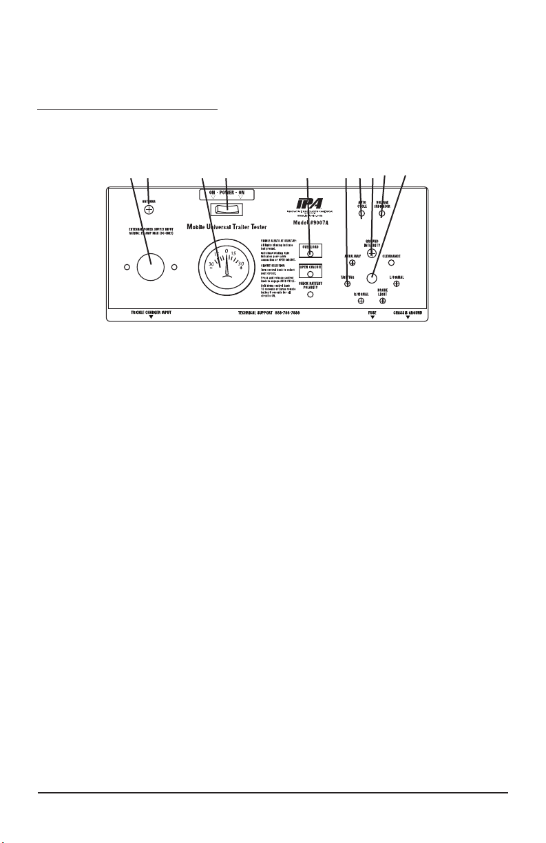
J I G H F E D C B A
Fig. 2 – Control & Information Panel
A. CONTROL KNOB (Fig. 2)
Knob activates all electrical test modes and circuits to be diagnosed.
• Manual Mode • Auto Cycle Mode
• Warning Sound Bypass • “All Circuits On” Mode
• Brake Light Exercise Mode
B. VOLTAGE INDICATOR (Fig. 2)
Shows battery supply voltage integrity.
• Operating Voltage: 12/24 Volt DC • Voltage Cut Off: 11/23 Volt DC
C. GROUND INTEGRITY (Fig. 2)
Large green LED above the Control Knob indicates ground status. Ground integrity
is automatically veried when power is turned on. If a ground fault is indicated, attach
the supplied 10 foot ground cord to the chassis of the trailer. If the fault clears, the
problem is in the chassis ground. If the fault continues, the problem is with the ground
return in the plug.
D. AUTO CYCLE INDICATOR (Fig. 2)
Illuminates when Auto Cycle is engaged.
Auto Cycle tests all circuits in 5 second intervals in clockwise rotation (you cannot access Auto Cycle Mode when in Auxiliary or Brake Mode). To enter Auto Cycle Mode,
press control knob once and then a second time to cancel Auto Cycle Mode.
9
Page 10

E. CIRCUIT INDICATORS (Fig. 2)
The small green LEDs illuminate or blink in testing phase.
F. TROUBLE WARNING INDICATORS
Flashing red LEDs indicate problems that may exist in a selected circuit.
• Overload Indicator
• Open Circuit Indicator
• Reversed (Battery) Polarity Indicator
G. BACKLIT 30 AMP AMMETER (Fig. 2)
Meter shows current draw of a selected circuit up to 30 amps.
H. POWER SWITCH (Fig. 2)
Select between internal battery, external power supply, or power off.
• Center: OFF (battery charge in this position only).
• Left: internal battery ON.
• Right: external power ON (power supply is an optional accessory).
I. ANTENNA (Fig. 5 & Fig. 2)
Receives RF signal from wireless remote up to 100 feet.
Binding post allows antenna length insertion for further distances in inclement
weather. It is recommended the antenna be installed for optimum performance.
J. 20 AMP INDEPENDENT POWER INPUT SOURCE (Fig. 2)
Use for connection of external 20 amp power supply. (Power supply is an optional
accessory. Not for battery charging.)
DC POWER ONLY
Do not plug directly into
AC wall outlet.
10
Page 11
POWER PANEL FEATURES
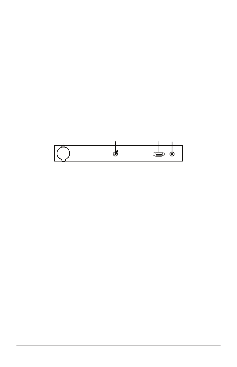
K. 12V DC BATTERY TRICKLE CHARGE INPUT (Fig. 3)
Use for connection of trickle charger to battery. Allows oat charge to be kept on bat-
tery when unit is not in use.
L. MUTE SWITCH (Fig. 3)
Flip switch up to mute alerts.
M. 30 AMP FUSE SOCKET (Fig. 3)
Overload protection.
N. CHASSIS GROUND OUTLET (Fig. 3)
Insert supplied ground cable into this socket for trailers using the frame or body for
ground connection instead of ground pin in harness.
POWER PANEL
K L
Fig. 3 – Power Panel
M N
ELECTRICAL/LIGHT TESTING PROCEDURES
7 ROUND PIN TRAILER TESTER
MANUAL MODE
To avoid false readings, visually inspect trailer socket for corroded and/or
squeezed pins.
Bad or broken socket pins can cause false readings. (Replace socket if pins are
broken or socket appears to have been subjected to extreme heat. Clean all
connections and load socket with dielectric grease).
1. Prior to any MUTT® testing, connect the 7 pin connector or you will receive
erroneous readings. The MUTT® is intended to be used while connected to a
trailer or while cable testing.
2. Secure battery connections to tester.
3. Make sure the Remote Key Fob has been programmed. (pg. 15)
4. Insert the provided 7 round cable to the socket on the right side of the tester.
5. Before testing trailer lights, test the 7 pin cable with the socket on the left side
of the MUTT® (cable tester).
11
Page 12

6. Using the red power selection switch (Fig. 2-H), select Power Source.
7. Check Voltage Indicator (Fig. 2-B) for green illumination. In the case of low or
weak supply voltage, yellow color illuminates. Red illumination from the Voltage
Indicator shows inadequate power supply.
Also see Warning Indicator section (pg. 18).
8. Initial power starts a test cycle through all the LEDs. This performs the
“GROUND INTEGRITY TEST.”
9. Ground Integrity Check: When the MUTT® is rst turned on, notice the
green lights circling the dial. This indicates the MUTT® testing for Ground
Integrity. If there is a lack of ground, all the green lights begin to ash to alert you
to the ground problem. If you only see one green LED ashing, this indicates an
Open Circuit (Check your 7 pin connections rst, then the trailer). If you do not
have Ground Integrity, the MUTT® cannot continue normal testing functions until
a solid ground is established. To troubleshoot, rst you need to understand the
type of ground being used on your particular trailer. There are two types: The rst
type is wired with each light receptacle grounded by the ground return wire
leading back through the 7 round pin plug at the front of the trailer. The second
type is chassis ground where the light receptacles are grounded directly to the
trailer chassis.
9a. If the trailer is grounded through the plug, the technician needs to locate the
source of this poor ground. Some systems use both wire and chassis
ground. Suggestion: Check the 7 way plug sockets and pin contacts FIRS
for loose or broken connections.
9b. If the trailer lights are chassis grounded, use the following instructions.
Your MUTT® comes supplied with a 10’ ground cable accessory. Plug in the
10’ ground cable to the MUTT® “Chassis Ground” Outlet (Fig. 3-N). Then
using the alligator clip, attach the other end of the ground cable to the
chassis of the trailer. This effectively grounds your trailer and allows testing
to continue.
10. After the “GROUND INTEGRITY TEST”, the Control Knob (Fig. 2-A) may be
rotated in either direction to select a circuit to diagnose. The corresponding
Circuit Indicator (Fig. 2-E) illuminates indicating the selected circuit.
AUTO CYCLE MODE
NOTE: Cannot be accessed when auxiliary or brake circuit is selected.
1. After Ground Integrity has been established, momentarily push and release the
Control Knob (Fig. 2-A). The Auto Cycle Indicator (Fig. 2-D) illuminates.
2. Power is applied by the MUTT® to one circuit at a time for 5 seconds
in a clockwise direction starting from the Ground Integrity Indicator
(Fig. 2-C).
3. A 5 second delay commences before power is applied to the rst circuit
automatically.
12
Page 13

4. To pause or stop the auto cycle mode, momentarily press and release the
Control Knob, turning off the Auto Cycle Indicator.
MUTING WARNING SOUND
How to override warning sound:
Flip MUTE switch up to disable audible alerts, or press Control Knob (Fig. 3-L) for 5
seconds. MUTE can not be accessed when AUX or Brake Circuits are selected.
To restore sound, return switch to down position and/or cycle power using the Power
Source switch.
ALL CIRCUITS ON (OVERRIDE)
Turns all circuits on (maximum load amount 20 AMPS total).
• ALL CIRCUITS ON” mode can be accessed by the Control Knob or Remote
Control:
• Hold down Control Knob for 10 seconds. Listen for the second beep and
release Control Knob.
• Hold down large button on remote for 5 seconds. On trailers using
incandescent bulbs, all circuits on will typically result in an “Overload”
because the amperage draw will exceed the allowed 20 amp maximum.
NOTE: Short Circuit sensing is operational in this mode. When Short Circuit is found
in this mode, the MUTT® will not be able to identify which circuit is the cause of the
short. Open Circuit sensing is not operational.
• To cancel “ALL CIRCUITS ON” mode, turn the selector knob or press and release
the large remote button.
ABS CODES
TO ACCESS ABS CODES:
Select the AUX or Brake light circuit, then press the Control Knob to ash either the
Brake or AUX line to access the trailer blink codes. Other methods include applying
and removing power to the AUX circuit in sequence with the ABS manufacturer’s
specications. Consult the ABS system of manufacturer’s manual for detailed
instructions. Below is a Diagnostic Chart referencing some of the ABS codes and
the method for releasing them from the CPU utilizing the SUPER MUTT®’s Auxiliary
circuit.
BLINK CODE DIAGNOSTICS
The Meritor WABCO Enhanced Easy—Stop Trailer ABS ECU detects any electrical
fault in the trailer ABS. Each of the faults has a code. When a fault occurs, the ECU
stores the code for that fault in the memory.
13
Page 14

There are two kinds of faults: active and stored. Active faults are those currently
existing in the system, such as a broken wire. Stored faults are faults that have
occurred but do not presently exist. Active faults can be cleared only after repairs are
completed.
The ECU signals a malfunction by lighting both the internal and external indicator
lamp when a fault exists. The external ABS indicator lamp is usually mounted on the
left rear of the trailer, near the rear wheels.
There are two ways to obtain blink codes:
» Ignition Power Activation (recommended method)
» Diagnostic Tool
Although the ECU can store multiple faults in its memory, it only displays one blink
code at a time. This is why it is important to re-check the blink codes after repairing
a fault. lf there are additional codes in the memory, they only blink after you have
repaired the rst fault.
Ignition Power Activation
Ignition Power Activation is the process of interrupting the power on the blue wire by
some other means (Auxilary Circuit) to display blink codes on the trailer ABS indicator lamp located on the side of the trailer. This method is for constant power vehicles
only.
To obtain blink codes using ignition power activation, perform the following prodcedure:
1. Activate Auxilary Circuit for no longer than 5 seconds. The ABS indicator lamp
will be on.
2. Turn the Auxilary Circuit off. The ABS indicator lamp will go out.
3. Turn the Auxilary Circuit on. The ABS indicator lamp will then come on, then
go out.
4. The blink code will be displayed three times by the ABS indicator lamp on
the trailer.
14
Page 15
BLINK CODES
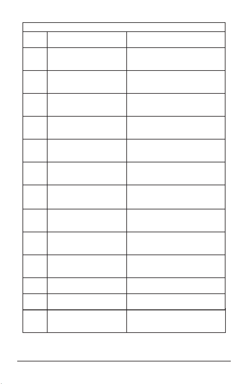
Blink
Code
3 Sensor BUl Determine sensor location. Check
4 Sensor YEl Determine sensor location. Check
5 Sensor BU2 Determine sensor location. Check
6 Sensor YE2 Determine sensor location. Check
7 External ABS Modulator
Valve
9 Internal modulator failure
inlet valve #2
10 Internal modulator failure
inlet valve #1
Problem Area Action
sensor installation. Make necessary
repairs.
sensor installation. Make necessary
repairs.
sensor installation. Make necessary
repairs.
sensor installation. Make necessary
repairs.
Verify proper electrical modulator
installation. Check power supply.
Make necessary corrections.
Verify proper installation. lf code
continues, contact Meritor WABCO
for assistance.
Verify proper installation. lf code
continues, contact Meritor WABCO
for assistance.
11 Internal modulator failure
outlet valve
Verify proper installation. lf code
continues, contact Meritor WABCO
for assistance.
14 Power Supply Verify proper electrical installation.
Check power supply. Make
necessary corrections.
15 ECU Failure Verify proper installation. If code
continues, contact Meritor WABCO
for assistance.
16 SAE Jl 708 Failure Internal failure, contact Meritor
WABCO.
17 SAE J2497 (PLC) Failure Internal failure, contact Meritor
WABCO.
18 Generic l/O Failure Verify proper electrical installation.
Check power supply. Make
necessary corrections.
For diagnostic and troubleshooting assistance, call Meritor WABCO at
1-800-535-5560
15
Page 16
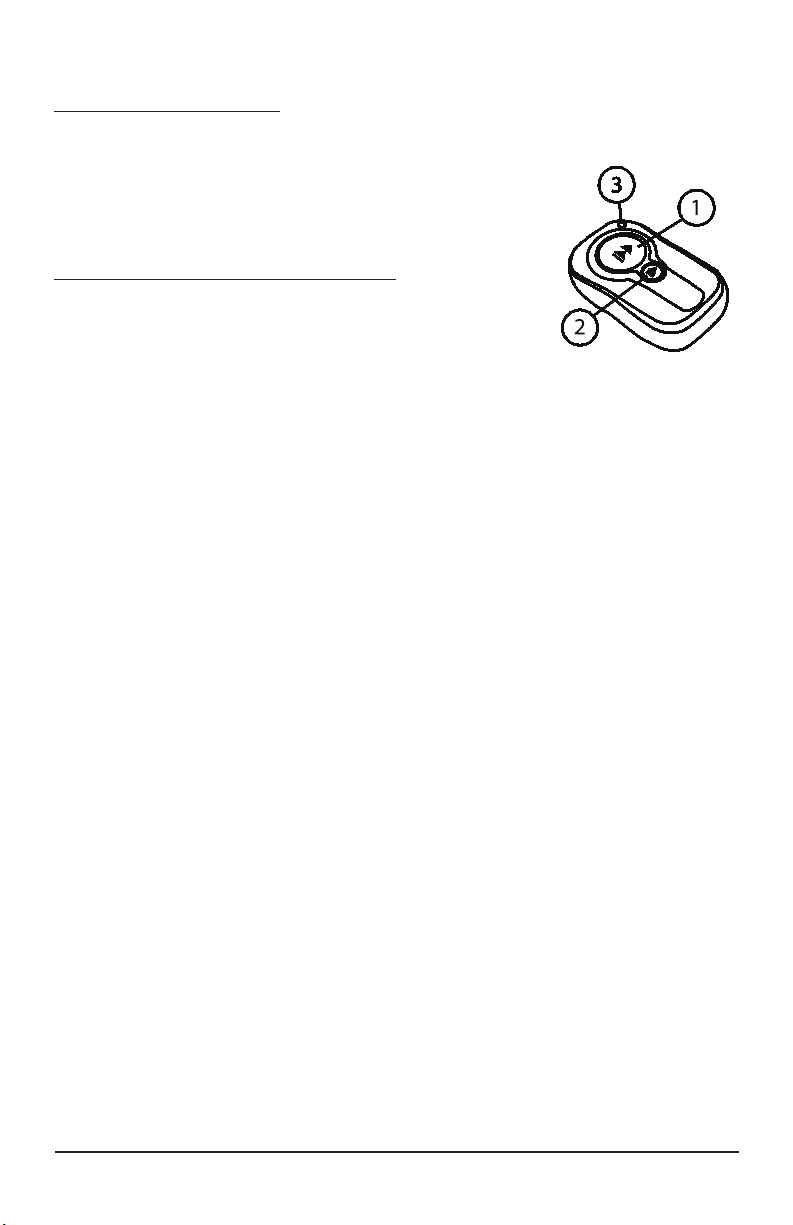
REMOTE FUNCTIONS
REMOTE PROGRAMMING
With MUTT® in the OFF position, hold down the large button (Fig. 4-1)
on the remote while simultaneously turning the MUTT® power
ON. Release after 2 seconds. The remote is now programmed.
Up to 24 separate remotes may be programmed to a single
MUTT®.
HOW TO USE THE WIRELESS REMOTE
LIGHTS & ELECTRIC BRAKES
1.
Press button to select the next available electrical
circuit (including electric brakes when available).
2. AUTO CYCLE
Press and hold button #2 for 3 seconds (Fig. 4-1) and the Smart MUTT® will enter
Auto Cycle Mode where a circuit is powered for 6 seconds before
the tester automatically begins powering the next circuit in clockwise sequence.
3. REMOTE CONFIRMATION INDICATOR
Red light illuminates to conrm that a button has
been pressed to indicate battery remote power.
NOTE: With each press of either button, the red light (Fig. 4-3) of the remote
illuminates, showing the conrmation of button depression and battery integrity of the
remote. Inclement weather, nearby power transformers and closely parked trailers
may cause reduction in remote signal.
Fig. 4: Remote
Control
An antenna wire is attached on pg. 22 of this manual (Fig. 5). The antenna can be
inserted into the MUTT® antenna jack (Fig. 2-I). It is recommended that the antenna
is installed upon set-up. In extreme scenarios, the operator may choose to install a
longer wire such as standard mechanic’s wire to achieve a better signal. This is only
necessary when working on trailers that are parked within 18” of each other. In
normal situations, the remote control will work from up to 75’ away from the MUTT®.
The Remote Key Fob Battery supplied is a 12V, Alkaline Energizer type A23. A Gold
Peak type 23AE or a Duracell MN21 battery can be used.
WARNING
Be careful when using remote controls in multi-bay shops where another
MUTT® may be in operation. One remote may be inadvertently programmed
to multiple MUTT®s. This can happen when the large button on a remote is
being held down at the same time another MUTT® is being powered up,
effectively programming one remote to two units. To avoid this, be sure any
other MUTT® users alert you to when they power up their unit. A remote
control can only be synchronized to a MUTT® during the power up phase.
16
Page 17
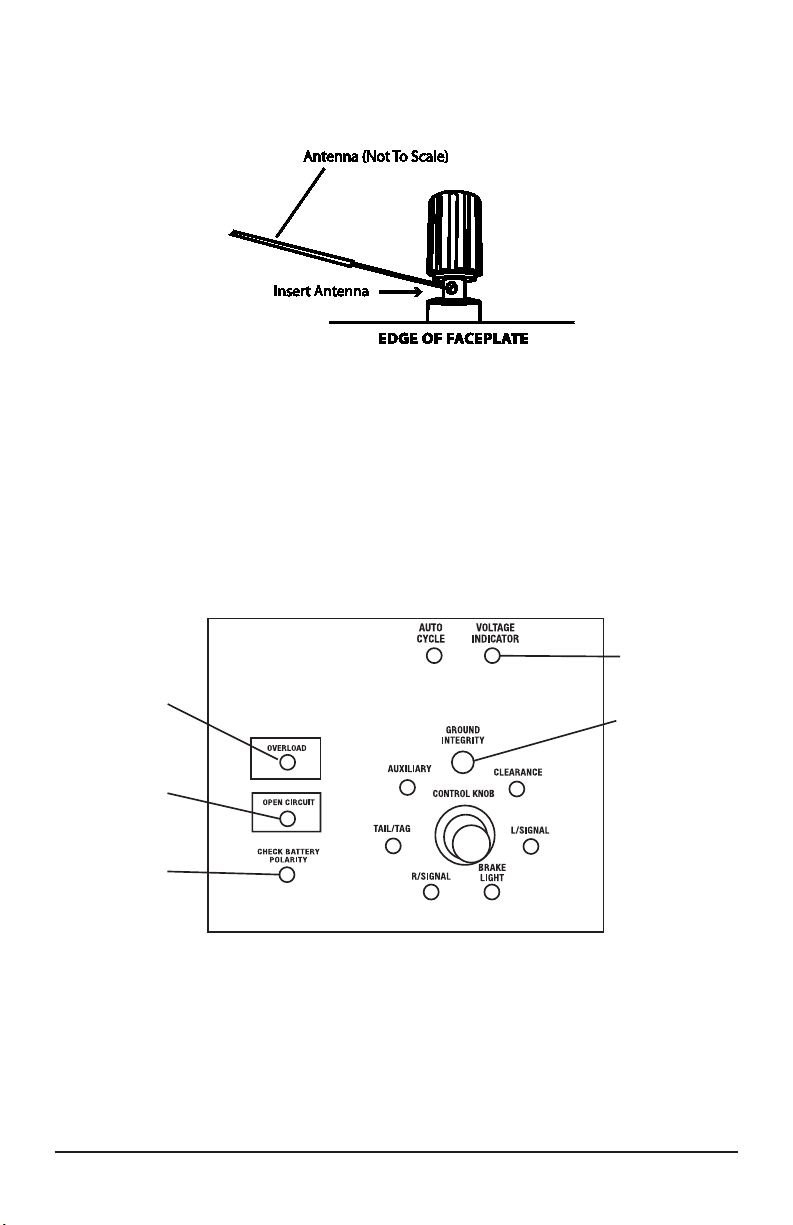
Explanation of the diagnostic functions of the warning indicators.
OVERLOAD
WARNING
INDICATOR
ANTENNA INSTALLATION
See Fig. 5 for installation of the Antenna.
Fig. 5: Antenna Installation:
WARNING INDICATORS
VOLTAGE
INDICATOR
GROUND
INDICATOR
OPEN
CIRCUIT
INDICATOR
REVERSE
POLARITY
INDICATOR
Fig. 6: Warning Indicators
17
Page 18

POWER TO TESTER WARNING INDICATORS
(See. Fig. 6)
VOLTAGE INDICATOR
• When the battery supply voltage drops to 9V or less, the MUTT® shuts down
power to all circuits and the voltage indicator ashes red.
• Charging or replacing the battery is required to continue testing.
• Between 10V-11V, the indicator is RED, showing the battery is too low.
• Between 11V-12V, the indicator is YELLOW, showing the battery is low.
REVERSED POLARITY INDICATOR
• Flashes when battery clamps have been crossed at the battery posts.
• Correcting polarity of the battery terminal clamps deactivates the warning.
• The MUTT® is internally protected from polarity reversal.
RED TRAILER WARNING INDICATORS
These signals indicate a fault.
OVERLOAD INDICATOR
• When the MUTT® confronts a constant amperage draw above 20 Amps or a
direct short, the indicator ashes and the beeper sounds.
• Voltage is cycled to the shorted or overloaded circuit in 3 second intervals to
aid in diagnosing the extreme amperage draw. (This function is comparable to
an auto reset circuit breaker). The MUTT® goes into “Pulsar Mode.”
OPEN CIRCUIT INDICATOR
• In the instance a selected circuit is not completed through the trailer harness,
(e.g., a faulty ground or no load detected), the Open Circuit warning ashes
and sounds.
CROSSED CIRCUIT WARNING CHARACTERISTICS
• Green Circuit Indicators ash to show troubled circuits.
• In the instance of crossed circuits where a circuit (or circuits) other than the
selected circuit are inadvertently powered by the selected circuit, the
unselected Circuit Indicators ash while the selected indicator remains steady.
This is caused by worn wires or improperly wired plugs on the trailer. In some
cases it may be normal for more than one circuit to be operated
by a single circuit, such as certain ABS systems and custom
aftermarket lighting.
• Refer to trailer specic wiring schematics for the unit in question.
GROUND INTEGRITY WARNING
(With the Use of Chassis Ground Cable)
Ground Integrity has been explained in Testing Procedure (Pg. 12, #9.)
AUTO SHUTDOWN FEATURE
To preserve battery life, the MUTT® enters a ‘sleep’ mode if inactive after 20 minutes
with the power ON.
• A sound is emitted every 10-20 seconds to inform the operator of the condition.
• Activation of any test mode takes the MUTT® out of ‘sleep’ mode.
18
Page 19

CABLE TESTING
The MUTT® has a special cable feature to test 7 round pin cables for continuity. The
cable testing feature can be used to test a tractor’s cable or the supplied MUTT® cable.
It is recommended that all cables be tested prior to MUTT® operation.
TEST PROCEDURE
PRIOR TO CABLE TESTING:
To avoid erroneous fault, be certain the 7 pins in each plug are clean
and spread to the proper size.
• Insert each end of the cable into both side connectors on the MUTT®.
Be sure to push the cable ends in rmly until they reach the bottom of the
connector.
• Turn main power switch ON.
• Once the power is turned ON, the green lights around the Control Knob will
blink and disappear one at a time until only the Ground Integrity light remains
solid green. Once the initial check has been performed, poor cable conditions
will be shown by a blinking light for the problem circuit.
• If the cable has an open circuit or continuity problem, the corresponding circuit
ashes repeatedly.
• Further testing can be performed by selecting each circuit individually via the
Control Knob or Remote. When an open circuit is detected, the LED for the
circuit will ash and an audible alert will be heard.
NOTE: Always check the MUTT® connector pins at the side of the MUTT® for proper expansion. Over time the pins may bend in slightly resulting in a poor connection between
the connector and the cable ends. A at head screwdriver can be used to expand the
pins until the a tight connection is made.
19
Page 20
12 VOLT
(12V)
BACK-UP
LIGHTS (BU)
ELECTRIC BRAKE
ELECTRIC
BRAKES
(EB)
KEYWAY
RIGHT
TURN
(RT)
LEFT
TURN
(LT)
GROUND
GROUND
(GD)
12 VOLT
(12V)
TAIL/TAG
BACK-UP
LIGHTS (BU)
ELECTRIC BRAKE
(EB)
ELECTRIC
BRAKES
(EB)
KEYWAY
LEFT
TURN
(LT)
CLEARANCE
AUX
(ABS)
STOP/BRAKE
RIGHT
TURN
(RT)
LEFT
TURN
(LT)
RIGHT
TURN
(RT)
GROUND
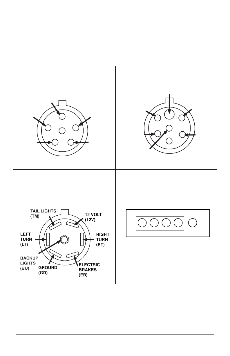
TYPICAL TRAILER WIRING
NOTE: Not all trailers/vehicles are wired to this standard. The use of an electrical circuit
tester is necessary to ensure proper match of vehicle’s wiring to trailer’s wiring. On the
6 way plugs, the 12V wire and electric brake wire may be reversed on some trailers
(particularly horse trailers).
ELECTRIC
BRAKES
(EB)
RIGHT
TURN
(RT)
6 PIN ROUND PLUG
ADAPTER END
TAIL
LIGHTS
(TM)
7-WAY FLAT PLUG
VEHICLE END
GROUND
(GD)
LEFT
TURN
(LT)
CLEARANCE
TRAILER SIDE 7 ROUND PIN
SOCKET CONFIGURATION
GROUND
(GD)
TAIL/TAG
LEFT
TURN
(LT)
AUX
(ABS)
STOP/BRAKE
RIGHT
TURN
(RT)
4/5 PIN PLUG
ADAPTER END
BU GN Y BR WH
20
Page 21

OPTIONAL ACCESSORIES & RELATED PRODUCTS
#9003A Mini MUTT® (RV Style) 7 Spade
#9004A Smart MUTT® (RV Style) 7 Spade
#9005A Super MUTT® Head 7-Way Round Pin w/ remote
#9008-SE Super MUTT® 7-Way Round Pin w/ remote
#9008-DL Super MUTT® 7-Way Round Pin w/ remote
#8026 4/5 Pin Towing Maintenance Kit
#8027 6 Round Pin Towing Maintenance Kit
#8028 7 Flat (Spade) Towing Maintenance Kit
#8029 7 Round Pin Towing Maintenance Kit
#7865L 7 Round Pin Tractor Trailer Circuit Tester
#7893 7 Flat (Spade) Pin Trailer Circuit Tester
#7897 6 Round Pin Tractor Trailer Circuit Tester
#7866 4/5 Pin Trailer Harness Checker
#8000 3-Way Trailer Adapater
#TSTPK1 Multi-Trailer Tester Jobber Pack
Innovative Products of America® Incorporated
www.IPATOOLS.com
845-679-4500 • 888-786-7899
234 TINKER STREET, WOODSTOCK, NY 12498
21
Page 22

NOTES
22
Page 23

NOTES
23
Page 24

Limited Three Year Warranty
009007A-MANUAL-IPA-PRINT.indd
MOBILE UNIVERSAL TRAILER TESTER
#9007A SMART MUTT
Innovative Products of America® Incorporated has established a Limited Three Year Warranty
Policy for the Mobile Universal Trailer Tester 9007A Series, not including any wearable parts,
i.e. tires, clips, batteries, etc.
Three Year Limited Warranty/Return or Replace Policy: The product is covered for three
years from the date of original user purchase under the stipulations of the Standard Warranty.
The product is warranted to be free from defects in workmanship or material. If there is a problem due to workmanship or material defect, Innovative Products of America® Incorporated will
repair or replace the product within 24 working hours after it is received by the IPA® Repair
Service Center. In the event it is determined that the product has been tampered with, or
altered in any way, the warranty is void and all claims against the product will not be honored.
The Warranty Repair/Return procedures require that the proof of purchase must be established (either by warranty card from the seller or by point of purchase receipt/invoice) and the
manufacturer makes every attempt to return ship the product within three business days from
the receipt of the returned product, freight prepaid.
If it has been determined that the tool has been damaged due to misuse, Innovative Products
of America® Incorporated will repair the tool at a cost we deem reasonable and these charges
will be the responsibility of the user. We truly want you to be happy with our products, so if you
have any questions, call us toll-free at 888-786-7899.
Innovative Products of America® Incorporated
234 Tinker Street, Woodstock, NY 12498
888-786-7899 / 845-679-4500 | www.ipatools.com
®
© 2012 Innovative Products of America®, Incorporated. All rights reserved. This material may not be reproduced, displayed, modied or
distributed without the express prior written permission of the copyright holder. For permission, contact [email protected].
 Loading...