

IOWA MOLD TOOLING Diamond Air DA440PBU PTO, Diamond Air 80 PTO User Manual

DA440PBU: 99900403: i20020104
Model DA440PBU
PTO, Belt Driven
Underdeck Compressor
(Previously Model 80 PTO, Blt Driven Underdeck)
IOWA MOLD TOOLING CO., INC.
BOX 189, 500 HWY 18 WEST, GARNER, IA 50438
TEL: 641-923-3711
TECHNICAL SUPPORT FAX: 641-923-2424
MANUAL PART NUMBER 99900403
DA440PBU: 99900403: ii
19980224
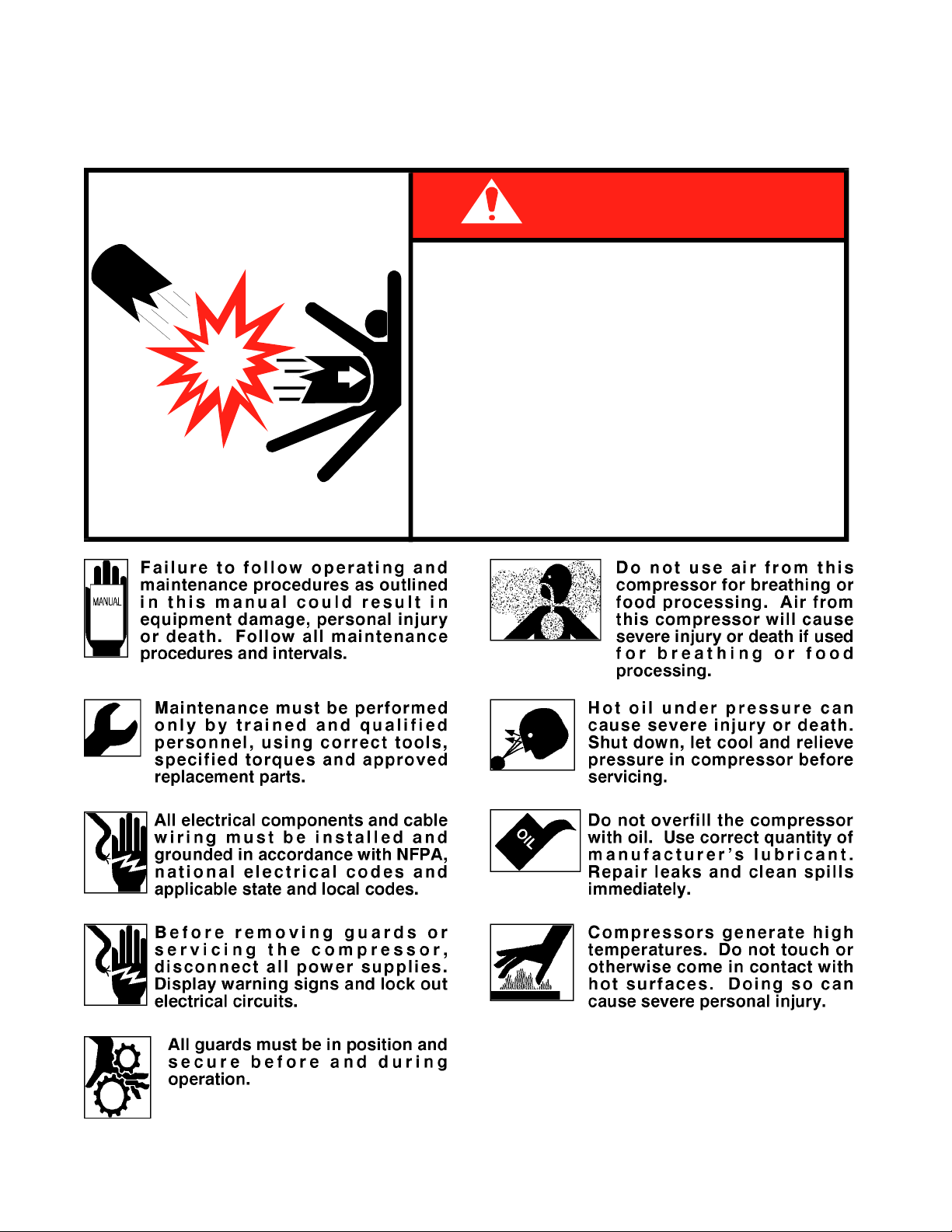
PRECAUTIONS
Read before operating your compressor!
DEATH, SERIOUS INJURY
●
Drain air tank after each use to prevent
moisture build-up and corrosion which
leads to tank failure.
●
Assure that tank and compressor relief
valves work properly, and are at correct
71393886
pressure settings.
●
DO NOT modify or repair air tank.
●
NEVER drive vehicle with pressure in air
tank.
DANGER
EXPLODING T ANK WILL CAUSE
OR PROPERTY DAMA G E

DA440PBU: 99900403: iii19990119
PARA TITLE PAGE
SPARE PARTS LIST iv
Section 1. INTRODUCTION
1-1. GENERAL INFORMATION 1-1 1-
2. ORDERING INFORMA TION 1-1
Section 2. INST ALLATION
2-1. GENERAL 2-1
2-2. PTO INSTALLATION 2-1
2-3. UNDER-DECK COMPRESSOR INSTALLATION 2-1
Section 3. OPERA TION
3-1. OPERATION 3-1
3-2. SYSTEM SHUTDOWN 3-1
Section 4. PREVENTIVE MAINTENANCE
4-1. GENERAL 4-1
4-2. LUBRICATION 4-1
4-3. PREVENTIVE MAINTENANCE CHECKLIST 4-1
Section 5. P ARTS
5-1. GENERAL 5-1
TABLE OF CONTENTS
Section 6. REFERENCE
LIST OF ILLUSTRATIONS
FIGURE TITLE (PART NUMBER) PAGE
D-1. TABLE - PREVENTIVE MAINTENANCE CHECKLIST 4-1
DA440PBU COMPRESSOR (23000086-1) 5-1
DA440PBU COMPRESSOR (23000086-2) 5-2
INST ALLATION KIT (93709888) 5-3
DA440PBU COMPRESSOR USING 8" DRIVE PULLEY (23000083-1) 5-4
DA440PBU COMPRESSOR USING 8" DRIVE PULLEY (23000083-2) 5-5
DA440PBU COMPRESSOR-CW TRANSMISSION (23000952-1) 5-6
DA440PBU COMPRESSOR-CW TRANSMISSION (23000952-2) 5-7
F-1. TORQUE DATA CHART 6-1
F-2. TIRE LOAD AND INFLATION PRESSURES 6-2

DA440PBU: 99900403: iv19980224
RECOMMENDED SPARE PARTS LIST
1 Y ear Supply
DA440PBU PTO, BELT DRIVEN UNDERDECK COMPRESSOR
For Manual: 99900403
This spare parts list does not necessarily indicate that the items can be expected to fail in the course of a year. It is intended to
provide the user with a stock of parts sufficient to keep the unit operating with minimal down-time waiting for parts. There
may be parts failures not covered by this list. Parts not listed are considered as not being Critical or Normal Wear items
during the first year of operations and you need to contact the distributor or manufacturer for availability.
SHELF
ASSEMBLY
DESIGNATION
LIFE
(MO)
ORDER
QTYCODEQTYDESCRIPTIONPART NO.ITEM NO.
23000086.01.19970620 PTO, BEL T DRIVEN UNDERDECK COMPRESSOR
23000083.01.19970205 PTO, BELT DRIVEN UNDERDECK COMPRESSOR USING 8" DRIVE PULLEY
COMPRESSOR (R30)-70073051
1 70058428 BELT-POWER V B66 2 C
2 70058620 BELT-V B38 2 C
17 60107965 PTO DRIVE SHAFT 1 W
19 70055062 PILLOW BLOCK 2 C
25 60111268 SHAFT 1 W
26 70055062 PILLOW BLOCK 2 C
29 73054031 UNLOADER VALVE 1 C
30 77041008 PRESSURE SWITCH 1 C
50 89086120 OIL-30WT NON-DETERGENT 1 P
55 70048069 MOISTURE REGULATOR 1 P
1 70058428 BELT-POWER V B66 2 C
2 70580106 BELT-V B40 2 C
17 60111269 PTO DRIVE SHAFT 1 W
19 70055062 PILLOW BLOCK 2 C
25 60111268 SHAFT 1 W
26 70055062 PILLOW BLOCK 2 C
29 73054031 UNLOADER VALVE 1 C
35 77041008 PRESSURE SWITCH 1 C
50 89086120 OIL-30WT NON-DETERGENT 1 P
55 70048069 MOISTURE REGULATOR 1 P
REF 70073727 LP INTAKE VALVE 1 W
REF 70073726 LP EXHAUST VALVE 1 W
REF 70732447 HP INTAKE VALVE 1 W
REF 73054340 HP EXHAUST VALVE 1 W
REF 70073766 RING SET 1 W
REF 70143298 RELEASE VALVE KIT 1 W
REF 70732429 INTERCOOLER TUBE LH 1 W
REF 70732430 INTERCOOLER TUBE RH 1 W
REF 70732448 AIR FILTERS 1 P
REF 76391490 SHAFT SEAL 1 W
REF 73054339 POP OFF 70PSI 1 W
REF 73054031 PILOT VALVE 1 C

DA440PBU: 99900403: 1-119940729
SECTION 1. GENERAL INFORMATION
1-1. INTRODUCTION
This manual provides information on the
installation, operation and repair of the IMT
DA440PBU PTO, belt driven underdeck
compressor.
Three means are used throughout this manual to gain
the attention of operating and service personnel.
They are NOTES, CAUTIONS and WARNINGS
and are defined as follows:
NOTE
A NOTE IS USED TO EITHER CONVEY ADDITIONAL
INFORMATION OR TO PROVIDE FURTHER EMPHASIS
FOR A PREVIOUS POINT.
CAUTION
A CAUTION IS USED WHEN THERE IS THE STRONG
POSSIBILITY OF DAMAGE TO THE EQUIPMENT OR
PREMA TURE EQUIPMENT FAILURE.
WARNING
A W ARNING IS USED WHEN THERE IS THE POTENTIAL
FOR PERSONAL INJURY OR DEATH.
1-2. ORDERING INFORMATION
When placing orders or requesting assistance, refer
to the information below:
Operate this equipment with respect and service it
regularly. These two things can add up to a safer
working environment and longer equipment life.
TO BE COMPLETED BY DEALER
CHASSIS INFORMA TION
TRANSMISSION MAKE:
PTO NUMBER:
COMPRESSOR AND HYDRAULIC PUMP INFORMATION
COMPRESSOR MODEL:
PUMP MAKE:
RESERVOIR CAPACITY:
MODEL:
PTO %:
SERIAL NUMBER:
MODEL:
ENGINE RPM:

DA440PBU: 99900403: 1-219940729
NOTES
DA440PBU: 99900403: 2-119990119
SECTION 2. INSTALLATION
2-1. GENERAL
This section deals with the installation of the PTO.
The instructions are intended as a guide to assist you
with your particular installation. We can not cover
every make, model and year of truck manufactured
world-wide, so these instructions will provide only
general information. Use this information as a guide
only.
2-2. PTO INSTALLATION
Power take-off manufacturers provide specific
installation instructions for their products. Those
instructions should be followed when installing a
PTO. Some trucks may require modification of the
transmission cross-member to provide clearance and
the exhaust pipe may need modification. Check with
the PTO manufacturer’s representative for specific
instructions regarding your particular make, model
and year of vehicle. The following instructions are a
guide in this application.
1. If the vehicle is new, drain the transmission oil
into a clean container for reuse. If the vehicle is
used, drain and dispose of the transmission oil.
2. Temporarily install the PTO with the proper
gaskets and only two studs. Snug the PTO down and
check the backlash for maximum allowance of 1/32"
to 1/16". If the backlash is excessive, remove
gaskets and check backlash again until it is
corrected.
CAUTION
AVOID SHARP BENDS IN THE SHIFTER CABLE. ALL
BENDS SHOULD HAVE AT LEAST A 6" RADIUS.
TIGHTER BENDS WILL CAUSE DIFFICUL T OPERA TION
OF THE SHIFTER KNOB.
6. Replace the transmission oil. If the PTO is
located below the transmission oil level, an
additional quantity of oil will be required.
7. Start the engine, engage the PTO and allow it to
run for 5 - 10 minutes. Check for leaks, unusual
noise and proper operation.
8. Retorque the mounting bolts.
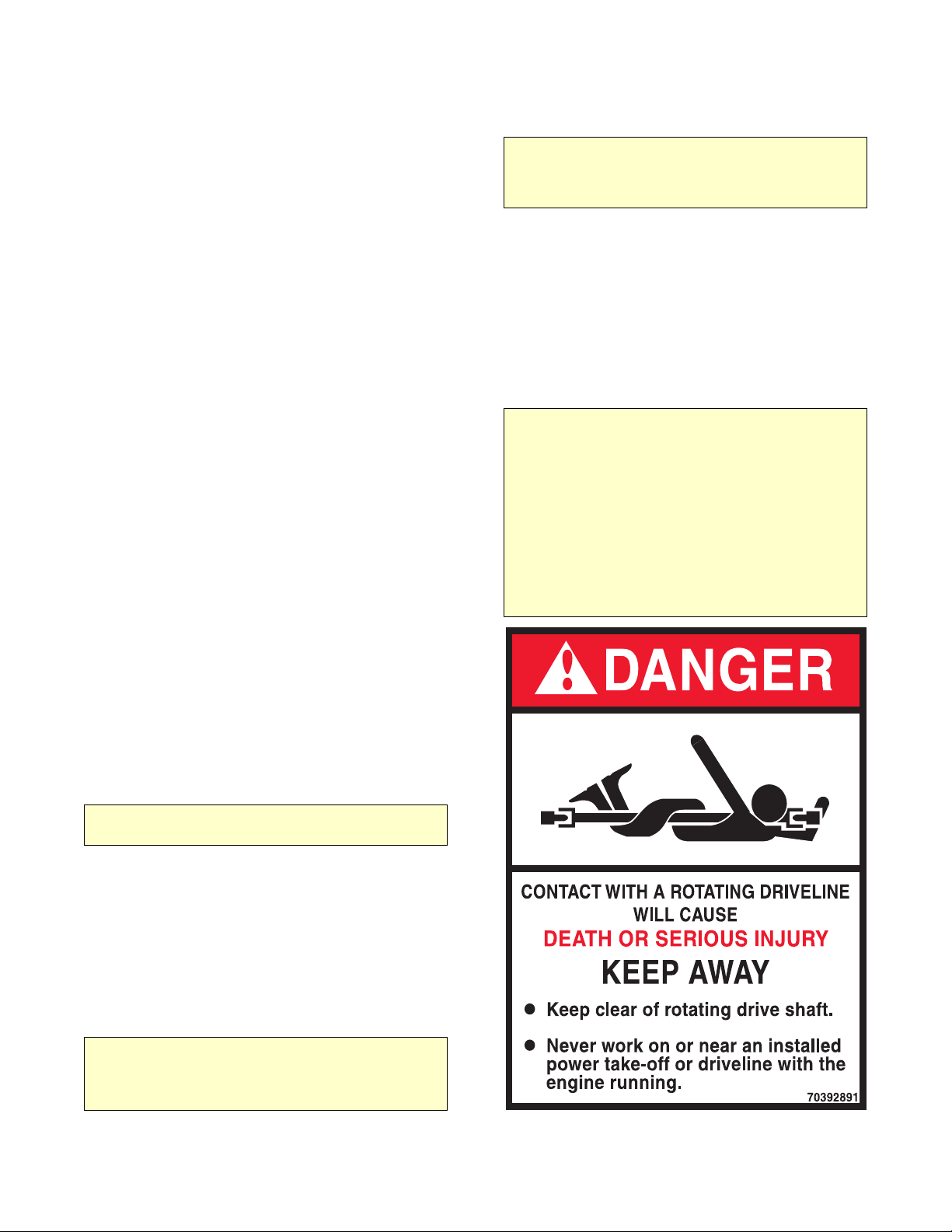
WARNING
THE INSTALLER OF THE DRIVELINE MUST INSPECT
THE FINAL POSITION OF THE DRIVELINE TO
DETERMINE WHETHER ITS LOCATION PROVIDES
SUFFICIENT PROTECTION TO AN OPERATOR, OR
OTHER PERSONNEL, FROM HAZARDS ASSOCIATED
WITH A ROTATING DRIVELINE. IF PROTECTION IS
INSUFFICIENT, THE INSTALLATION OF A GUARD IS
REQUIRED. IF YOU ARE UNSURE OF METHODS TO
GUARD A ROTATING DRIVELINE, CALL IOWA MOLD
TOOLING CO., INC. FOR INSTRUCTIONS. FAILURE
TO DO SO MAY RESULT IN SERIOUS INJURY OR
DEATH.
3. Remove the PTO and apply Permatex to the
gaskets. If the holes for the studs are tapped through
the transmission housing, apply Permatex to the
studs and tighten them down. Make certain that the
studs do not interfere with the transmission gears.
CAUTION
AVOID CONTACT OF PERMATEX WITH AUTOMATIC
TRANSMISSION FLUID.
4. Install the PTO and gaskets. Torquethe nuts to
30 - 35 ft-lbs (4.14 - 4.84 kg-m) for a 6-bolt PTO
and 45 - 50 ft-lbs (6.22 - 6.91 kg-m) for 8-bolt
PTO’s. Recheck the backlash.
5. Install the shifter cable to suit conditions.
Always allow for a slight overshift on lever or knob
to ensure the PTO is fully disengaged.
CAUTION
IT IS IMPORTANT THAT ADEQUATE SPACE BE
ALLOWED FOR FULL ENGAGEMENT OF THE PTO.
MODIFY THE EXHAUST OR OTHER OBSTRUCTIONS
AS NEEDED.

DA440PBU: 99900403: 2-219990119
2-3. UNDER-DECK COMPRESSOR INSTALLATION
Due to the large variety of carrier vehicles, the
instructions in this paragraph should be used as a
guide only .
1. Position the compressor below the bed of the
truck in the desired location. The location selected
should provide adequate ventilation while at the
same time affording protection against road hazards
and dirt.
2. Lift the compressor base into position. Check
for belt clearance and approximate drive shaft
length.
3. Using the base as a template, drill two holes 17/
32" diameter, and two holes on the other side of the
frame 21/32" diameter.
4. Bolt the compressor base to the frame of the
truck using the 1/2" and 5/8" hardware.
5. Using the appropriate driveshaft with knuckles
in place, measure the exact length required, cut off
excess shaft and weld in place (1/4" weld all
around).
6. Install the driveshaft to the PTO and the
compressor, tighten the lock bolts and tie-wire in
place.
7. Tighten all bolts.
8. Connect the 3/4" air hose from the compressor
to the air tank.
9. Install the engine speed control and connect the
hoses from compressor to speed control.
 Loading...